1
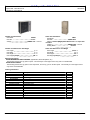
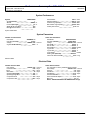
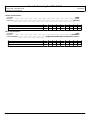
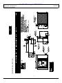
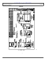
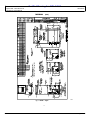
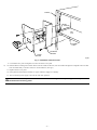
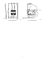
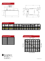
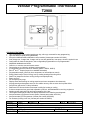
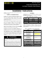
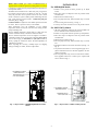
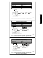
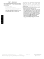
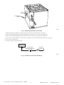
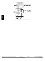
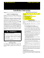
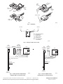
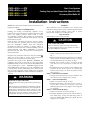
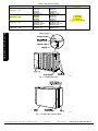
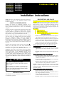
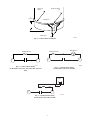
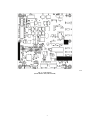
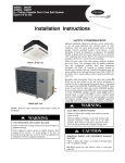
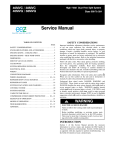
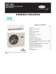
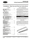
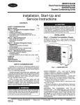
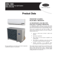
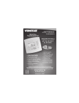
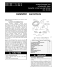
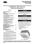
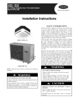
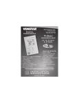
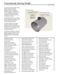
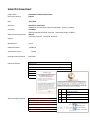
Submittal Coversheet
Project Name
DPS Project Number
DPS Moore k-8 General Renovation
PP2218
Date
6/17/2014
Architect
Short Elliot Hendrickson
2000 South Colorado Blvd Tower One Suite 6000 Denver, CO 80222
GH Phipps
5995 Greenwood Plaza Blvd. Suite 100 Greenwood Village, CO 80111
Walrath
7935 West 14th Ave Lakewood, CO 80215
Contractor
Subcontractor/Prepared by.
Supplier
Manufacturer
Carrier
Submittal Number
235400.01
Specification Section
235400
Drawing Number/Location
MDF 001A
Contractor Review
AHU-1 CU-1
THIS SUBMITTAL REVIEW IS FOR GENERAL COMPLIANCE WITH THE DESIGN CONCEPT OF
THE PROJECT AND GENERAL COMPLIANCE WITH THE INFORMATION GIVEN IN THE
CONTRACT DOCUMENTS. ANY ACTION SHOWN IS SUBJECT TO THE REQUIREMENTS OF
THE PLANS AND SPECIFICATIONS.
THE CONTRACTOR IS RESPONSIBLE FOR ALL
QUANTITIES, DIMENSIONS (WHICH ARE TO BE CORRELATED AT THE JOB SITE),
FABRICATION PROCESSES, MEANS, METHODS AND TECHNIQUES OF CONSTRUCTION,
COORDINATION OF THE WORK WITH THAT OF OTHER TRADES, AND THE SATISFACTORY
PERFORMANCE OF THE WORK IN A SAFE AND SATISFACTORY MANNER.
Architect/Engineer Review
Contractor to coordinate
RA/Filter plenum as noted on
plans for a vertical installation
with a bottom return air inlet.
Provide TXV as required per
manufacturer.
NET
NO EXCEPTIONS TAKEN
AOAN
APPROVED ONLY AS NOTED
(PROVIDE CONFIRMATION OF COMPLAINCE)
R
REJECTED
RR
REVISE AND RESUBMIT
SSI
SUBMIT SPECIFIED ITEM
Digitally signed by Kristin Blundell
DN: C=US,
[email protected],
O=The CE Group, CN=Kristin
Blundell
Date: 2014.06.18 11:05:00-06'00'
SUBMITTAL COVER SHEET
JOB: DPS – Dora Moore
LOCATION: Denver, CO
CONTRACTOR: Walrath
ENGINEER: The CE Group
EQUIPMENT
TAG
QTY
MODEL NUMBER
DESCRIPTION
AHU-1
1
FBRCNF030000
CU-1
1
38HDR024---3
AHU-1
1
KFADK0201DSC
FB4C Base Series Fan Coil with Puron, 30,000 BTU
Cooling, 208/230-1-60
Performance 13 Series Air Conditioner with
Puron, 2 Tons Cooling, 208/230-1-60
Electrical Disconnect Kit
“
1
VCMA15ULS
Little Giant Condensate Pump
“
1
T2900
Venstar Programmable Thermostat
“
1
ACC0400
Outdoor Temperature Sensor
CU-1
1
53DS-900---086
Low Ambient Control
“
1
KAAFT0101AAA
Evaporator Freeze Thermostat
“
1
KAATD0101TDR
Time-Delay Relay
“
1
KAAWS0101AAA
Winter Start Control
“
1
53DS-900---087
Wind Baffle
“
1
KAACH1401AAA
Crankcase Heater
“
1
38L58S38135PEB
35ft Insulated Line Set
LOHMILLER & COMPANY CERTIFIES THE ABOVE DATA TO BE A TRUE ABSTRACT OF
MANUFACTURES’ CURRENT RATINGS FOR THE PRODUCTS SHOWN.
DATE:
4800 OSAGE STREET
06/16/2014
PREPARED BY:
DENVER, COLORADO 80221
PHONE: (303) 825-4328
WWW.LOHMILLER.COM
Robert Bernal
FAX: (303) 820-2302
Fan Coil and Air
Conditioner
SUBMITTAL
Tag: AHU-1, CU-1
Model #: FB4CNF/38HDR
Electrical: 208/230 Volt - 1 Phase – 60 Hertz
Qty: 1 ea.
Revision Date: 06/16/14
4800 OSAGE STREET
DENVER, COLORADO 80221
PHONE: (303) 825-4328
WWW.LOHMILLER.COM
FAX: (303) 820-2302
Project: DPS - Dora Moore K-8
Prepared By: Robert Bernal
Unit Report
Performance Summary
Acoustic Summary
Certified Drawing
Table Of Contents
AHU-1 CU-1
06/16/2014
2
3
4
5
Page 1 of 7
Unit Report For AHU-1 CU-1
Project: DPS - Dora Moore K-8
Prepared By: Robert Bernal
06/16/2014
Unit Report
Outdoor Unit Parameters
Unit Model:
Unit Size:
Voltage:
38HDR
2 Tons
208/230-1-60 V-Ph-Hz
Outdoor Unit Dimensions and Weight
Unit Length:
Unit Width:
Unit Height:
Unit Shipping Weight:
0
0
0
198
in
in
in
lb
Indoor Unit Parameters
FB4C
Unit Model:
30,000 Btuh
Unit Size:
Cabinet Insulation:Single-piece cabinet with 1-in. super thick
insulation
208/230-1-60 V-Ph-Hz
Voltage:
No Heat
Heating Size:
Indoor Unit Dimensions and Weight
Unit Length:
Unit Width:
Unit Height:
Unit Shipping Weight:
22.06
17
49
122
in
in
in
lb
Warranty Information
OTHER RESIDENTIAL APPLICATIONS (Apartments, Rental Properties, etc.)
The warranty period is five (5) years on parts. The warranty is to the original owner only and is not transferable.
OTHER APPLICATIONS
The warranty period is five (5) years on the compressor, and one (1) year on all other parts. The warranty is to the original owner
only and is not transferable.
Ordering Information
Part Number
Outdoor Unit
38HDR024---3
Accessories
53DS-900---086
KAAFT0101AAA
KAATD0101TDR
KAAWS0101AAA
53DS-900---087
KAACH1401AAA
Indoor Unit
FB4CNF030000
Accessories
KFADK0201DSC
Description
Quantity
Performance 13 Series Air Conditioner with Puron 2 Tons Cooling
13 SEER @ ARI Conditions
1
1
Low Ambient Control
Evaporator Freeze Thermostat
Time-Delay Relay
Winter Start Control
Wind Baffle
Crankcase Heater
1
1
1
1
1
1
FB4C Base Series Fan Coil with Puron 30000 BTU Cooling
Single-piece cabinet with 1-in. super thick insulation
1
1
Disconnect Kit
1
Page 2 of 7
Performance Summary For AHU-1 CU-1
Project: DPS - Dora Moore K-8
Prepared By: Robert Bernal
06/16/2014
Performance Summary
System Performance
System:
System Quantity:
Altitude:
Linear Pipe Length:
SEER @ ARI Conditions:
EER @ ARI Conditions:
38HDR/FB4C
1
5200.0 ft
0.0 ft
14.5
12.0
Actual Airflow:
Standard Airflow:
Total Net Clg Capacity:
Net Sensible Clg Capacity:
Total System Power:
968.7
800.0
20.89
20.89
2.19
CFM
CFM
MBH
MBH
kW
System Parameters
System Parameters
Outdoor Unit Parameters
Unit Model:
Unit Size (Nominal):
Voltage:
Clg Ent Air DB Ambient:
38HDR024---3
2 Tons
208/230-1-60 V-Ph-Hz
105.0 °F
Indoor Unit Parameters
Unit Model:
Unit Size (Nominal):
Voltage:
Ent Air DB:
Ent Air WB:
Ent Enthalpy:
Lvg Air DB:
Lvg Air WB:
Lvg Enthalpy:
Heating Size (Nominal):
Indoor Unit External Static:
FB4CNF030000
30,000 Btuh
208/230-1-60
80.00
62.00
30.45
55.82
54.06
24.65
No Heat
0.20
V-Ph-Hz
°F
°F
BTU/lb
°F
°F
BTU/lb
in wg
Electrical Data
Electrical Data
Outdoor Electrical Data
Unit Voltage:
Fan Motor FLA:
MCA:
Max Fuse:
Operating Range Min:
Operating Range Max:
Compressor RLA:
Compressor LRA:
208/230-1-60
0.80
17.7
25
197
253
13.5
58.3
V-Ph-Hz
Amps
Amps
Amps
V
V
Amps
Amps
Indoor Electrical Data:
(For units with no factory installed electric heaters)
208/230-1-60 V-Ph-Hz
Unit Voltage:
2.8 Amps
Unit FLA:
3.5 Amps
Unit MCA:
15.0 Amps
Unit MOCP:
14.0
Unit Min Wire Size:
15.0 Amps
Unit Fuse/Ckt Bkr Amps:
1/3 HP
Motor HP:
Notice: Indoor Elect. data is for 208/230-1-60 voltage
Page 3 of 7
Acoustic Summary For AHU-1 CU-1
Project: DPS - Dora Moore K-8
Prepared By: Robert Bernal
06/16/2014
Acoustic Summary
Outdoor Unit Parameters:
Unit Model:
Unit Size:
Variations:
Octave Band Center Frequency, Hz
Sound Power,dB
A-Weighted Sound Power, dBA
Indoor Unit Parameters:
Unit Model:
Unit Size:
Cabinet Insulation:
Octave Band Center Frequency, Hz
Sound Power,dB
A-Weighted Sound Power, dBA
38HDR
2 Tons
Standard
63
0.0
125
57.5
250
61.5
500
63.0
1k
61.0
2k
60.0
4k
56.0
8k
45.0
dBA
69.0
FB4C
30,000 Btuh
Single-piece cabinet with 1-in. super thick insulation
63
67.0
125
63.0
250
59.0
500
56.0
1k
54.0
2k
52.0
4k
48.0
8k
0.0
dBA
0.0
Page 4 of 7
X
X
X
X
X
X
O
O
O
O
O
O
230-1-60
208-230-1-60
O
O
O
X
X
X
O
O
O
X
X
X
18,24
30,36,48,60
23" X 42"
24" X 50"
B
B
X = YES
O = NO
25 1/8" 36 15/16"
31 1/8" 36 15/16"
37 3/16" 44 9/16"
37 3/16" 44 9/16"
43 3/16" 44 9/16"
43 3/16" 44 9/16"
MINIMUM
UNIT SIZE MOUNTINGPAD
DIMENSIONS
A
38HDR018 1
38HDR024 1,2
38HDR030 1
38HDR036 1
38HDR048 1,2
38HDR060 1,2
208/230-3-60
ELECTRICAL A
UNITSERIES
CHARACTERISTICS
DIM ENSI ONS -- ENGLI SH
460-3-60
C
F
D
E
F
E
G
AIR
H
22"
28"
34 1/16"
34 1/16"
40 1/16"
40 1/16"
7 1/2"
AIR
17 1/8"
23 1/8"
29 3/16"
29 3/16"
35 3/16"
35 3/16"
L
FIELDCONTROLSUPPLY
WIREENTRY
7/8"HOLEW/GROMMET
17 3/16"
17 3/16"
19 5/8"
19 5/8"
19 5/8"
19 5/8"
MVAPORLINECONN.
FEMALESWEATCONN.
23 7/16"
23 7/16"
30 1/2"
30 1/2"
30 1/2"
30 1/2"
11/16"
16"
16"
18 7/16"
18 7/16"
18 7/16"
18 7/16"
D C
14 9/16"
14 9/16"
17 1/16"
17 1/16"
17 1/16"
17 1/16"
N
1"
J
J
P
13"
14"
13 11/16"
13 11/16"
14 1/2"
14 1/2"
K
K
6 5/8"
6 3/4"
8 1/8"
8 1/8"
8 1/2"
8 1/2"
L
M
5/8"
5/8"
3/4"
3/4"
7/8"
7/8"
N
2 15/16"
2 15/16"
3 7/16"
3 7/16"
3 7/16"
3 7/16"
8"
4 1/2"
1 1/2"
G
JUNCTIONBOX FOR
POWERSUPLLYAND
CONTROLCONNECTIONS
4 3/16"
2 1/2"
11 1/4"
11 5/8"
15 7/8"
15 7/8"
18 7/8"
18 7/8"
H
1 7/16"
F, MAX.125
155
180
200
218
284
294
171
198
223
240
309
319
SHIPPING
P OPERATING
WEIGHT(lbs)
WEIGHT(lbs)
6"
6"
6 1/2"
6 1/2"
6 1/2"
6 1/2"
38HDR
Project: DPS - Dora Moore K-8
Prepared By: Robert Bernal
Certified Drawing for AHU-1 CU-1
06/16/2014
Certified Drawing
8
Page 5 of 7
Certified Drawing for AHU-1 CU-1
Project: DPS - Dora Moore K-8
Prepared By: Robert Bernal
06/16/2014
DIMENSIONS
A12512
Fig. 1 -- FB4CNF --English
4
Page 6 of 7
Certified Drawing for AHU-1 CU-1
Project: DPS - Dora Moore K-8
Prepared By: Robert Bernal
06/16/2014
(cont.)
DIMENSIONS
A12508
Fig. 2 -- FB4CNP --English
5
Page 7 of 7
Electrical
Disconnect
SUBMITTAL
Tag: AHU-1
Model #: DFADK0201DSC
Qty: 1
Revision Date: 06/16/14
4800 OSAGE STREET
DENVER, COLORADO 80221
PHONE: (303) 825-4328
WWW.LOHMILLER.COM
FAX: (303) 820-2302
Installation Instructions
Electrical Disconnect Kit
KFADK0201DSC
NOTE: Read the entire instruction manual before starting the installation.
This symbol → indicates a change since the last issue.
SAFETY CONSIDERATIONS
Improper installation, adjustment, alteration, service, maintenance, or use can cause explosion, fire, electrical shock, or other conditions which may
cause personal injury or property damage. Consult a qualified installer, service agency, or your distributor or branch for information or assistance.
The qualified installer or agency must use factory authorized kits or accessories. Refer to the individual instructions packaged with the kits or
accessories when installing.
Follow all safety codes. Wear safety glasses and work gloves. Read these instructions thoroughly and follow all warning or cautions attached to
the unit. Consult local building codes and National Electrical Code (NEC) for special requirements.
Recognize safety information. This is the safety-alert symbol . When you see this symbol on unit or in instructions and manuals, be alert to
potential for personal injury.
Understand the signal word DANGER, WARNING, CAUTION, and NOTE. These words are used with safety-alert symbol. DANGER identifies
most serious hazards which will result in severe personal injury or death. WARNING signifies hazards which could result in personal injury or
death. CAUTION is used to identify unsafe practices which would result in minor personal injury or product and property damage.
WARNING: Before beginning any installation or modification, be sure the main electrical disconnect switch is in the
OFF position. Tag side connect switch with suitable warning label. Electrical shock can cause personal injury or death.
INTRODUCTION
This instruction covers the installation of electrical disconnect kit Part No. KFADK0201DSC used with FA, FB, FC, FK, FX, FV, 40FK, and PF
fan coils. The kit is designed to provide a manual electrical disconnect for units with cooling controls and heaters 3kw through 10kw.
DESCRIPTION AND USAGE
When pull-out is removed on access panel the disconnect allows safe service and maintenance to be performed on the load side of disconnect.
Disconnect Assembly
1
Window Bezel
1
No. 10 Hex Head Screw 3
Installation Instruction 1
WARNING: Field wires on the line side of the disconnect are live even with the pull-out removed. Any service or
maintenance to incoming wiring must be performed with the main disconnect switch tuned off. Failure to do so will result
in electrical shock causing personal injury or death.
INSTALLATION
1. Turn off electrical supply to fan coil unit.
2. Remove cover plate on blower access panel.
3. Remove blower access panel.
4. Remove pull-out and cover plate from disconnect assembly. Retain cover plate screw.
5. Attach disconnect mounting bracket to unit casing and blower shelf with 2 No. 10 hex head screws provided in kit. Bracket will mount near
high-voltage line entry. (See Fig. 1.)
6. Replace yellow and black high voltage pigtail wires from heater with yellow and black wires supplied with disconnect kit. Make sure new
wires are installed at the same location from which they were removed.
7. Attach load and line wires to disconnect. (See Fig. 2.) Insert wires into wire connectors. Tighten lugs on line side. Connect ground wire
to unit ground lug.
8. Replace cover plate on disconnect assembly using 1 No. 10 hex head screw provided and retained cover plate screw. (See Fig. 1.)
Form:
AG-FADK-01
Cancels:
AG-FB4A-20
Printed in U.S.A.
3-03
Catalog No.
63FA-DK0
CASING
UNIT
GROUND
FAN
COIL
BLOWER
SHELF
MOUNTING
BRACKET
COVER
PLATE
A90084
Fig. 1—Installation of Disconnect Kit
9. Cut insulation away from rectangular access hole in blower access panel.
→
10. Remove adhesive backing from window bezel. From the outside of the door, insert the window through the rectangular hole in the door.
Press the frame firmly on the door surface to seat the adhesive. (See fig.3)
11. Replace blower access panel.
12. Insert pull-out into disconnect assembly so copper conductors engage for continuity.
13. Turn on electrical power supply to fan coil unit and check operation.
CAUTION: Disconnect pull-out is not intended to interlock with upper access panel. Upper access panel can be
removed without disconnecting power.
—2—
ADHESIVE
LINE
WINDOW BEZEL
PULL TO
DISCONNECT
LOAD
GROUND
PRIOR TO ADHERING WINDOW SEAL TO DOOR PANEL,
MAKE CERTAIN THAT THE RECTANGULAR CUTOUT IS
DOWN.
NOTE: Route wires as shown
A00001
A03064
Fig. 2—Wiring Connections
Fig. 3—Installation of Bezel
—3—
Condensate Pump
SUBMITTAL
Tag: AHU-1
Model #: VCMA15ULS
Electrical: 115 Volt - 60 Hertz
Qty: 1
Revision Date: 06/16/14
4800 OSAGE STREET
DENVER, COLORADO 80221
PHONE: (303) 825-4328
WWW.LOHMILLER.COM
FAX: (303) 820-2302
HVAC
VCMA-15 Series
Applications
••Designed for automatic collection and removal of
condensate from air conditioning, refrigeration and
dehumidification equipment when gravity drainage
is not possible or practical. Also suitable for high
efficiency oil and gas-fired condensing furnace and
condensing boiler equipment.
Features
••1/2 gallon collection tank
••Vertical centrifugal pump design
••Automatic start and stop operation
••Some models equipped with float (solid polymer)
activated switch for automatic high level water
detection (safety overflow switch)
••For models with safety overflow switch: dual function
NO and NC operation (set to NO from factory for
equipment shut down connection)
••Models equipped with safety overflow switch include
••
two 5” switch lead wires
3/8” O.D. barbed discharge adapter with built-in
check valve
••Three 1-1/8” diameter inlet openings (two fitted with
removable cap plug)
••Thermally protected, fan cooled motor
••Built-in wall mount tabs on tank
••Removable pump float locking tab for safety during
transportation (remove at time of installation)
••Maximum water temperature: 140 ºF
••6 ft, 3-conductor cable with grounded 3-prong plug
••Some models include 20’ x 3/8” I.D. vinyl
discharge tubing
Specifications
••Motor — 1/50 hp
••Discharge — 3/8" OD barbed
••Housing/tank cover — ABS
••Motor cover — ABS
••Volute — ABS
••Tank — ABS
••Impeller — Glass filled polypropylene
••Check valve — Acetal
Wastewater • Water Systems • HVAC • Industrial • Engineered Products
Engineering Data
"
"
"
"
"
"
"
"
"
"
"
"
"
Specifications
Item
No.
Model
No.
Discharge
Size
Performance (GPH@Head)
HP
Volts
Hertz
Amps
Watts
1'
5'
10'
Shutoff
20'
Ft
PSI
Cord
Length (ft)
Weight
(lbs)
554401
VCMA-15UL
3/8" OD Barbed
1/50
115
60
1
60
65
50
25
0
15
6.5
6
4.40
554411
VCMA-15ULT
3/8" OD Barbed
1/50
115
60
1
60
65
50
25
0
15
6.5
6
5.80
554405
VCMA-15ULS
3/8" OD Barbed
1/50
115
60
1
60
65
50
25
0
15
6.5
6
4.40
554415
VCMA-15ULST
3/8" OD Barbed
1/50
115
60
1
60
65
50
25
0
15
6.5
6
5.80
200
250
NOTE: GPH is through check valve.
Replacement Parts
Part Number
154401
Cover, motor
154421
Float arm
154452
Switch holder
154471
Switch
950337
Check valve
154715
Flow - Liters/Hour
0
50
100
150
16
4.5
14
4.0
12
3.5
10
3.0
8
2.5
2.0
6
1.5
4
Head - Meters
Tank
Head - Fees
Item
Performance Data
1.0
2
0.5
0
0.0
0
10
20
30
40
50
60
70
Flow - Gallons/Hour
P.O. Box 12010
Oklahoma City, OK 73157-2010
Phone: 1.800.701.7894
Fax: 1.800.678.7867
www.LittleGiantPump.com
Form 995124 – 08/12
Thermostat and
Sensor SUBMITTAL
Tag: AHU-1
Model #: T2900/ACC0400
Qty: 1 ea.
Revision Date: 06/16/14
4800 OSAGE STREET
DENVER, COLORADO 80221
PHONE: (303) 825-4328
WWW.LOHMILLER.COM
FAX: (303) 820-2302
Venstar Programmable Thermostat
T2900
STANDARD FEATURES:
• Up to 3-Occupied, 1-Unoccupied periods per day, with copy command for easy programming
• Light Activated occupied period (defeatable)
• Accepts humidification/dehumidification control module (Venstar part number ACC0430)
• Auto changeover, 3-stage heat, 2-stage cool for use with gas/electric, heat pump, electric & hydronic heat
• Configurable for manual changeover, also configurable programmable or non-programmable
• Adjustable deadbands and timers
• Control to, or monitor a second remote sensor
• Can average up to 8 (wired or wireless) remote sensors
• 3 configurable outputs for maximum flexibility (MISC1, MISC2, MISC3)
• Extra 6th and 7th outputs (beyond our standard thermostat)
• Programmable output (control by time, temperature or internet/phone control)
• Energy Watch keeps Track of energy use by tracking heating and cooling hours
• Smart Fan (keeps the fan from running during unoccupied periods)
• Smart recovery
• Pre-occupancy fan purge
• Display shows both heating an cooling setpoints and room temperature simultaneously
• All programming and setpoints stored in non-volatile memory, and are never lost in power failure
• Service filter and service UV lamp indicators
• Red/Green LED shows whether thermostat is calling for heating or cooling
• 5-minute compressor time guard and adjustable cycle limit, both defeatable for servicing equipment
• Outdoor sensor ready with high and low temperature of the day
• Thermoglow backlit electro-luminous display and backlit color coded keys and legends
• Accepts accessory IR Remote Control system (Venstar part number ACC0431)
• Accepts accessory EZ Programmer (Venstar part number ACC0432)
• For accessory locking cover use (Venstar part number ACC0620)
MODEL:
JOB NAME:
LOCATION:
BUYER:
ENGINEER:
1
QUANTITY:
DPS - Dora Moore K-8
846 Corona Str., Denver, CO 80128
T2900
Walrath
The CE Group
DATE:
BUYER P.O.#:
06/16/2014
wired sensors
accessories
Model ACC0401
The remote indoor temperature sensor with override
button offers the user the ability to change commercial
thermostats to Occupied mode for after-hours heating
or cooling. It will measure indoor-air temperature at a
remote location from the thermostat. It is a digital
sensor designed for use with Venstar thermostats. It
can be used with the Venstar T1800, T1900, T2700,
T2900, T2900SCH and T2300FS thermostats.*
The sensor will sense room temperature where it is
installed. The thermostat will control to the remote
temperature sensor reading and show a blinking
degree icon next to the temperature display on
the thermostat.
models:
1.4”w x 1.8”h x .63”d
ACC0401, TB400,
ACC0400, & ACC0435
model TB400
model ACC0400
model ACC0435
A drop down remote temperature sensor
The outdoor air sensor allows the outdoor
air temperature to be sent to the thermostat. It can be used with the T1100FS,
T1700, T1800, T1900, T2700, T2800,
T2900, T2300FS or TSTATEZ thermostats.*
The high and low outdoor air readouts for
the day can be displayed on the T1800,
T1900, T2800 and T2900 thermostats.*
The Remote Duct Sensor for Venstar
thermostats is a digital temperature
sensor. Constructed with plenum-rated
cable, it is designed to be installed
inside the return air duct. A grommet
is included to protect the cable from
the edge of the sheet metal.
•Quick and Easy to Install
•Ensure proper zone temperature
•Mock surveillance camera design deters robbery, theft, and
vandalism
•Compatible with Surveyor Energy Management System
•Includes T-bar Hanger Bracket
(3/4” standard PVC not included)
TB400 is compatible with
the Venstar T1800, T1900,
T2700, T2900, T2900SCH
and T2300FS thermostats.*
Operating temperature range: -40˚
to +125˚ F.
When used as a remote room sensor,
the accessory can be used with the
Venstar T1800, T1900, T2700, T2900,
T2900SCH and T2300FS thermostats.*
The sensor may sense
room temperature where
it is installed. The
thermostat will control
to the remote temperature sensor reading and
show a blinking degree
icon next to the
temperature display
on the thermostat.
This sensor may also be used as a
remote room sensor where a discreet
sensor is required. When used as a
remote room sensor, this accessory
can be used with the Venstar T1800,
T1900, T2700, T2900, T2900SCH
and T2300FS thermostats.* The
sensor will sense room temperature
where it is installed. The thermostat
will control to the remote temperature
sensor and show a blinking degree
icon next to the temperature display
on the thermostat.
2.7”w x 4.5”h x .45”d
* For a complete list, contact VENSTAR.
© Venstar Inc.
88-654
4.08
Low Ambient, Evap
Freeze T-stat, TimeDelay Relay, Winter
Start Control,
Wind Baffle,
Crankcase Heater
SUBMITTAL
Tag: CU-1
Model #: 53DS-900---086,
KAAFT0102AA, KAATD0101TDR,
KAAWS0101AAA, 53DS-900---087,
KAACH1401AAA
Qty: 1 ea.
Revision Date: 06/16/14
4800 OSAGE STREET
DENVER, COLORADO 80221
PHONE: (303) 825-4328
WWW.LOHMILLER.COM
FAX: (303) 820-2302
53DS---900--- --- ---086
53DS---900--- --- ---095
Duct---Free Systems
Cooling Only and Heat Pump Units
Low Ambient Temperature Control Accessory
Installation Instructions
NOTE: Read and become familiar with these instructions before
beginning installation.
SAFETY CONSIDERATIONS
Installing and servicing air--conditioning equipment can be
hazardous due to system pressures and electrical components. Only
trained and qualified personnel should install or service
air--conditioning equipment. When working on air--conditioning
equipment, observe the precautions provided in literature, tags, and
labels attached to the unit.
Follow all safety codes. Wear safety glasses, protective clothing,
and work gloves. Use quenching cloth for brazing operations.
Have fire extinguisher available. Read these instructions
thoroughly and follow all warnings or cautions included in
literature and attached to the unit. Consult local building codes and
National Electrical Code (NEC) for special requirements.
Recognize safety information. This is the safety--alert symbol !! .
When you see this symbol on the unit and in instructions or
manuals, be alert to the potential for personal injury.
Understand these signal words: DANGER, WARNING, and
CAUTION. These words are used with the safety--alert symbol.
DANGER identifies the most serious hazards which will result in
severe personal injury or death. WARNING signifies hazards
which could result in personal injury or death. CAUTION is used
to identify unsafe practices which may result in minor personal
injury or product and property damage. NOTE is used to highlight
suggestions which will result in enhanced installation, reliability, or
operation.
!
GENERAL
IMPORTANT: Heat pump models require an isolation relay and
field wiring to prevent fan cycling in heat pump mode. See Table 1
for isolation relay part numbers.
Table 1 – Isolation Relay Part Numbers
Models
38MVQ009/012
38MVQ012
38MVQ018/024
38QRR/QRF
538B_R/538Q_R
RCD
Part No.
P283--- 0291
P283--- 0292
P283--- 0292
P283--- 0293
P283--- 0293
Voltage
120v
240v
240v
24v
24v
Wind baffles are required for low ambient operation. For 38HD,
38QR and 538B models, the baffles are a factory accessory (see
Table 2 for part numbers). For 38MVC and 38MVQ models, the
baffles are field fabricated using factory drawings (see Table 2 for
drawing numbers).
Table 2 – Wind Baffle Accessories for R--410A Units
Models
38HDF/QRF/HDR/QRR018
538E_F/538Q_F018
38HDF/38HDR024, 38HDF030,
38QRF/38QRR024
538E_F/538A_R024
538E_F030
538Q_F/538B_R024
38HDF036/38QRF030/035/036,
38HDR/38QRR030/036
538E_F036
538Q_F030/035/036,
538A_R/538B_R030/036
38HDR/QRR048,060
538A_R/538B_R048,060
WARNING
ELECTRICAL SHOCK HAZARD
Failure to follow this warning could result in personal injury
or death.
Before beginning any modification or installation of this kit,
be sure the main electrical disconnect is in the OFF position.
Ensure power is disconnected to the fan coil unit. On some
systems both the fan coil and the outdoor unit may be on the
same disconnect. Tag the disconnect switch with a suitable
warning label. There may be more than one disconnect.
Models
38MVC/38MVQ009
38MVC/38MVQ012
38MVC/38MVQ018
38MVC/38MVQ024
*Drawings available on HVAC Partners.
1
Wind Baffle Part No.
53DS--- 900--- --- --- 070
53DS--- 900--- --- --- 087
53DS--- 900--- --- --- 071
53DS--- 900--- --- --- 088
Wind Baffle Drawing
No.*
53DS--- 900--- --- --- 097
53DS--- 900--- --- --- 097
53DS--- 900--- --- --- 098
53DS--- 900--- --- --- 099
Winter Start Control (part number KAAWS0101AAA) is
required when low ambient operation (cooling below 55_F/13_C)
is required for cooling and heat pump models (018--060) that have
a low pressure switch.
INSTALLATION
For 38HDR/QRR Models
1. Remove access panels and locate pressure tap on liquid
header.
2. Place three drops of compressor oil in the pressure switch
for lubrication.
3. Mount switch as shown in Fig. 1.
4. For heat pump units only, mount isolation relay in control
box.
5. Connect wiring as shown in Fig. 3 or Fig. 4.
6. Coil any excess wire and secure next to the pressure switch.
53DS-- 900-- -- -- 086, 095
The Winter Start Control kit uses a time--delay relay to bypass the
low--pressure switch for three (3) minutes on start--up. the time
delay relay will take the low pressure switch out of the control
circuit to allow the system to build pressure eliminating nuisance
trips. Units with low pressure switches: 38HDR/HDF/QRR/QRF
and 538A_B/E_F, 538Q_F.
Crankcase Heater is required for low ambient operation and must
be added. This is a separate accessory to be installed.
These instructions cover the installation of low ambient
temperature control accessory kit on the duct--free cooling and heat
pump condensing units.
The low ambient temperature control (LAC) is a high cycle rate
pressure switch that directly controls the outdoor fan motor.
The low ambient temperature control is designed to maintain a
condensing pressure of 255 to 295 psig on models 38MVC/MVQ
and 321 to 362 psig for HDF/HDR and QRF/QRR models by
directly cycling the outdoor--fan motor. No field adjustments or
calibrations are required.
When unpacking the accessory, carefully inspect for shipping
damage. If damage is evident, return for replacement.
For 38MVC/MVQ Models
1. All of the components required for the correct installation of
the low ambient control are included in the kit.
2. Remove access panels and locate pressure tap on liquid line.
3. Place three drops of compressor oil in the pressure switch
for lubrication.
4. Mount switch as shown in Fig. 2.
5. For heat pump units only, mount isolation relay in control
box.
6. Determine locations for electrical connections (see Fig. 3 or
Fig. 5).
7. Cut pressure switch leads to correct length and apply the required terminations from the selection supplied in the low
ambient control kit.
8. For heat pump units only, use the cut off lead and terminations supplied with the kit to make up the required field
wires as shown in Fig. 5.
LOW AMBIENT CONTROL
PRESSURE SWITCH
PRESSURE TAP ON
COIL LIQUID HEADER
LOW AMBIENT CONTROL
PRESSURE SWITCH
PRESSURE TAP ON
COIL LIQUID LINE
D06005
A08046
Fig. 1 -- Representative of 38HDR/38QRR OR 538A/538B
Models
Fig. 2 -- Representative of 38MVC/38MVQ Models
2
COOLING ONLY MODELS
Wire Color
Black = 009 & 012
Red = 018 & 024
Black
Black
Black
Black
38MVC009--- 024
38HDF018--- 036
38HDR018--- 060
538A Series
538E Series
LAC
SEE CHART
FOR COLOR
BLU
TO TERMINAL
CONNECTION
MAIN POWER
BLU
FAN MOTOR
LEGEND
LAC = Low Ambient Control
A08047
Fig. 3 -- Low Ambient Temperature Control Wiring -- Cooling Only Models
HEAT PUMP MODELS
(Reversing Valve Energized in Cooling)
Model No.
Wire Color
38QRF018--- 036
Black
38QRR018--- 060
Black
538BNR018--- 060
Black
538QNF018--- 036
Black
4
3
"RVS" *(REVERSING VALVE)
IR
"RVS" *(REVERSING VALVE)
5
1
SEE CHART
FOR COLOR
LAC
OUTDOOR
FAN MOTOR
IR
=
LAC =
TO TERMINAL
CONNECTION
MAIN POWER
LEGEND
Isolation Relay
Low Ambient Control
*Isolation relay coil (low voltage) to be wired in parallel with the reversing valve.
A08048
Fig. 4 -- Low Ambient Temperature Control Wiring -- Heat Pump Models
(Reversing Valve Energized in Cooling)
HEAT PUMP MODELS
(Reversing Valve Energized in Heating)
Model No.
Wire Color
38MVQ009--- 012
Black
38MVQ018--- 024
Red
4
3
IR
2
RVS
1
Field Wire - Use cutoff wire from
LAC and terminations supplied in the kit.
SEE CHART
FOR COLOR
LAC
OUTDOOR
FAN MOTOR
TO TERMINAL
CONNECTION
MAIN POWER
LEGEND
IR
= Isolation Relay
LAC = Low Ambient Control
RVS = Reversing Valve Solenoid
*Isolation relay coil (line voltage) to be wired in parallel with the reversing valve.
A08049
Fig. 5 -- Low Ambient Temperature Control Wiring -- Heat Pump Models
(Reversing Valve Energized in Heating)
3
53DS-- 900-- -- -- 086, 095
Model No.
CHECK OPERATION
53DS-- 900-- -- -- 086, 095
Before starting the system to check operation of low ambient
temperature control, ensure that the power wiring and location of
control assembly are correct. To check operation of low ambient
temperature control:
1. Turn power on to system.
2. Set thermostat below room temperature.
3. Ensure that there is the standard 3--minute time delay for the
microprocessor controlled high wall fan coil systems.
4. Check time delay of installed accessories:
Under--ceiling (40QAC/QAQ) fan coils using the duct--free
24--v thermostat delay settings: 2 or 4 minute delay.
Copyright 2008 CAC / BDP S 7310 W. Morris St. S Indianapolis, IN 46231
The outdoor--fan motor will not operate until the condensing
pressure reaches the control set point of 295 psig for
38MVC/MVQ models or 362 psig for 38QRF--018--036 and
38QRR--018--060 models (± 10 psig). When the set point is
reached, the outdoor fan will cycle to maintain the set point
condensing pressure.
If the low ambient temperature control does not operate correctly:
S Ensure that power is being supplied to the system.
S Check condensing pressure: if condensing pressure is below 255
psig for 38MVC/MVQ models or 321 psig for 38QRF--018--036
and 38QRR--018--060 models, the outdoor--fan motor should be
off and there should be no voltage across the 2 blue fan power
leads coming out of the control. If condensing pressure is about
295 psig or greater for 38MVC/MVQ models or 362 psig for
38QRF--018--036 and 38QRR--018--060 models, the
outdoor--fan motor should be on and will cycle off at around
255 psig for 38MVC/MVQ or 321 psig for 38QRF--018--036
and 38QRR--018--060 models.
Printed in U.S.A.
Edition Date: 02/08
Manufacturer reserves the right to change, at any time, specifications and designs without notice and without obligations.
4
Catalog No: IIK-- 53DS900-- 06
Replaces: AG--53DS900--01
Installation Instructions
Evaporator Freeze Thermostat
KAAFT0101AAA
NOTE: Read the entire instruction manual before starting the installation.
This symbol → indicates a change since the last issue.
INTRODUCTION
This instruction covers the installation of evaporator freeze thermostat Part No. KAAFT0101AAA on split-system air conditioners and heat pumps.
The device is designed to shutdown the outdoor section in the event of indoor coil freeze up, preventing damage to the compressor.
SAFETY CONSIDERATIONS
Installation and servicing of air conditioning equipment can be hazardous due to system pressures and electrical components. Only trained
personnel should install or service air conditioning equipment.
Untrained personnel can perform basic maintenance functions such as cleaning coils, or cleaning and replacing filters. All other operations should
be performed by trained service personnel. When working on air conditioning equipment, observe precautions in the literature, tags, and labels
attached to the unit.
Follow all safety codes. Wear safety glasses and work gloves. Use quenching cloth for brazing operations. Have fire extinguisher available.
. When you see this symbol on the unit and in instructions or manuals, be alert
Recognize safety information. This is the safety-alert symbol
to the potential for personal injury.
Understand the signal words DANGER, WARNING, and CAUTION. These words are used with the safety-alert symbol. DANGER identifies the
most serious hazards which will result in severe personal injury or death. WARNING signifies hazards which could result in personal injury or
death. CAUTION is used to identify unsafe practices which would result in minor personal injury or product and property damage.
DESCRIPTION AND USAGE
The evaporator freeze thermostat is recommended to prevent coil freezing. The kit contains the following items:
Temperature switch HH22JB026 1
Installation Instructions
1
WARNING: Before beginning any installation or modification, be sure the main electrical disconnect switch is in the
OFF position. Electrical shock can cause personal injury or death.
INSTALLATION
→ The following items must be provided by the field:
Standard 4 X 4-in. electrical box and cover
No. 8-32 X 1/2-in. sheet metal screws
No. 10-24 X 1/2-in. sheet metal screws
Wire ties
16-guage wires (length to be determined by installer)
Insulation (Arm-flex) for bulb coverage
1
2
2
2
2
PROCEDURE 1—MOUNT THERMOSTAT
1. Remove knockout in bottom of electrical box.
2. Drill two 3/16-dia clearance holes in right-hand side of electrical box 1 in. apart. Position holes in side of box to ensure clearances for
mounting of thermostat. (See Fig. 1.)
3. From within box, pass evaporator freeze thermostat bulb through knockout hole. Do not mount thermostat to box at this time.
4. Attach evaporator freeze thermostat bulb to vapor line, using 2 wire ties, as close to evaporator coil as possible. (See Fig. 1.)
5. Position electrical box on side of plenum or coil casing. Be sure location is NOT near coil surface. Drill two 9/64 or No. 27 holes through
holes provided in electrical box into plenum or casing.
CAUTION: Exercise extreme caution when drilling holes. Do not puncture coil and/or tubing.
Form:
AG-AAFT-02
Cancels:
AG-AAFT-01
Printed in U.S.A.
9-97
Catalog No.
63AA-FT0
3⁄16-IN.
HOLES
TO CONTROL
WIRING
A97510
→ Fig. 1—Mounting Thermostat on Coil Casing
6. Mount electrical box to plenum or casing using 2 No. 10-24 X 1/2-in. sheet metal screws. (See Fig. 1.)
7. Mount evaporator freeze thermostat to side of electrical box using 2 No. 8-32 X 1/2-in. sheet metal screws.
8. Route wires for bulb through knockout hole in electrical box, and connect to evaporator freeze thermostat.
9. Wire evaporator freeze thermostat in series with Y low-voltage wire from indoor thermostat at indoor unit. (See Fig. 2.)
10. Secure cover to electrical box.
11. Insulate evaporator freeze thermostat bulb.
INDOOR
THERMOSTAT
Y
EVAPORATOR
FREEZE THERMOSTAT
OUTDOOR
CONTACTOR
C
A97511
→ Fig. 2—Evaporator Freeze Thermostat Wiring
© 1997 CAC/BDP
P.O. Box 70, Indianapolis, IN 46206
agaaft02
—2—
Book/Tab: 1/3a, 4/2a
Catalog No. 63AA-FT0
TIME--DELAY
RELAY KIT
KAATD0101TDR
Installation Instructions
NOTE: Read the entire instruction before beginning the
installation.
INTRODUCTION
The Time--Delay Relay permits the indoor fan to briefly continue
to operate and provide additional cooling after the compressor
cycles off.
SAFETY CONSIDERATIONS
Installing and servicing air conditioning equipment can be
hazardous due to system pressure and electrical components.
Only trained personnel should install or service air conditioning
equipment.
Untrained personnel can perform basic maintenance functions,
such as cleaning coils and cleaning and replacing filters. All other
operations should be performed by trained service personnel.
When working on air conditioning equipment, observe
precautions in the literature, and on tags and labels attached to the
unit.
Follow all safety codes. Wear safety glasses and work gloves. Use
a quenching cloth for brazing operations. Have a fire extinguisher
available.
!
WARNING
ELECTRICAL SHOCK HAZARD
Failure to follow this warning could result in personal
injury or death.
Before beginning any modification be sure the main
electrical disconnect is in the OFF position. TAG SWITCH
WITH A SUITABLE WARNING LABEL.
INSTALLATION
!
CAUTION
ELECTRICAL OPERATION HAZARD
Failure to follow this caution may result in personal injury.
Before installing this kit, be sure high-- and low--voltage
electrical power to indoor section is disconnected.
NOTE: Check to make sure no components inside cabinet are
within drilling range.
2. Paint edges of screw holes to resist rust. Install mounting
screws through time--delay relay and into screw holes.
Tighten screws securely but do not overtighten.
!
CAUTION
ELECTRICAL OPERATION HAZARD
Failure to follow this caution may result in personal injury
or equipment damage.
The time--delay relay and low--voltage wiring should be
physically separated from high--voltage components and
wiring.
3. Refer to Fig. 1 for wiring connections.
4. Connect red wire from time--delay relay to terminal R on
low--voltage terminal board in fan coil or furnace.
5. Connect brown wire from time--delay relay to terminal C
on low--voltage terminal board.
6. Splice wire from thermostat terminal G to black wire from
time--delay relay.
7. Connect orange wire from time--delay relay to terminal G
on low--voltage terminal board.
8. Affix wiring label next to indoor unit wiring label.
9. Check all connections. Turn on electrical power.
10. Affix caution label on indoor unit access panel to electrical
controls.
11. To check function of system, set thermostat to operate in
cooling mode. With system “calling for cooling” run for
minimum of 5 minutes, then slowly move cooling lever
on thermostat to higher setting to satisfy thermostat. Once
the thermostat is satisfied, the indoor fan will continue to
run approximately 90 seconds, then shut off.
!
CAUTION
UNIT DAMAGE HAZARD
Failure to follow this caution may result in equipment
damage.
1. Using screws provided, mount time--delay relay to fan coil
or furnace cabinet. Position time--delay relay in convenient
place so that wires will be close to connection point. Drill
0.125 in. (use 1/8 drill size) screw holes into cabinet.
This accessory package includes an adhesive--backed
warning sticker. Affix this sticker prominently to fan coil or
furnace after installation.
FAN-COIL OR FURNACE
LOW-VOLTAGE
TERMINAL BOARD
R
G
Y
W
C
FIELD CONNECTIONS
BRN
RED ORN
BLK
KAATD
1/ 8 IN. DIA
FAN
TIME- (2) SCREW
DELAY
HOLES
FROM G ON
THERMOSTAT
2 15/16″
1 15/16″
Fig. 1 -- Typical Time--Delay Relay Wiring Connection
Copyright 2006 CAC / BDP S 7310 W. Morris St. S Indianapolis, IN 46231
Printed in U.S.A.
Edition Date: 05/06
Manufacturer reserves the right to change, at any time, specifications and designs without notice and without obligations.
2
Catalog No: AG-- KAATD-- 02
Replaces: AG--AATD--01
KAAWS0101AAA
Winter Start Control
Installation Instruction
NOTE: Read the entire instruction manual before starting the
installation.
SAFETY CONSIDERATIONS
Installing and servicing air conditioning equipment can be
hazardous due to system pressures and electrical components. Only
trained personnel should install or service air conditioning
equipment.
Untrained personnel can perform basic maintenance functions such
as cleaning coils, or cleaning and replacing filters. All other
operations should be performed by trained service personnel.
When working on air conditioning equipment, observe precautions
in the literature, on tags, and on labels attached to the unit.
Recognize safety information. This is the safety--alert symbol !! .
When you see this symbol on the unit and in instructions or
manuals, be alert to the potential for personal injury.
Understand these signal words; DANGER, WARNING, and
CAUTION. These words are used with the safety--alert symbol.
DANGER identifies the most serious hazards which will result in
severe personal injury or death. WARNING signifies hazards
which could result in personal injury or death. CAUTION is used
to identify unsafe practices which may result in minor personal
injury or product and property damage. NOTE is used to highlight
suggestions which will result in enhanced installation, reliability, or
operation.
Follow all safety codes. Wear safety glasses and work gloves.
!
WARNING
ELECTRICAL SHOCK HAZARD
Failure to follow this warning could result in personal injury or
death.
Before beginning any installation or modification, be sure the
main electrical disconnect switch is in the OFF position. TAG
THE DISCONNECT SWITCH WITH A SUITABLE
WARNING LABEL.
This kit is for 24 VAC applications ONLY. Do Not use or
connect to any high voltage wiring.
Use only the kit components described in this installation
procedure.
INTRODUCTION
This instruction covers the installation of winter start control Part
No. KAAWS0101AAA on split--system air conditioners. The
device is designed to alleviate nuisance opening of the
low--pressure switch by bypassing it for the first 3 minutes of
operation.
DESCRIPTION AND USAGE
Winter start control must be used where low evaporator
temperatures, or nuisance tripping of low--pressure switch may be
encountered.
The kit contains the following items:
(1) Time--Delay Relay (TDR) CESO130062--00
(1) Installation Instructions
(1) 13” (330 mm) Blue (tap) Wire
(1) 13” (330 mm)Yellow Wire
(1) 13” (330 mm) Brown Wire
(1) Insulated Tap Connector (HY89TC014)
INSTALLATION
NOTE: If a fully communicating Infinity/Evolution Control is
being used for low ambient cooling, a winter start control is not
required.
For outdoor units with Infinity/Evolution and TechAssist
single--stage control boards:
1. Mount the winter start control board in outdoor control box.
2. Connect the following wires to the TDR:
S 13” (330 mm) Yellow wire to T1 (24 VAC input)
S 13” (330 mm) Brown wire to T3 (24 VAC common)
S 13” (330 mm) Blue--tap wire to T2 (N.O. relay contact)
3. Secure the open end of Blue Tap wire to the insulated tap
connector (see Fig. 1). To do this, simply butt the tap--wire
against the wire stop. Fold the top cover half over to meet
the base. Squeeze on the top cover and base with ordinary
pliers until the latch locks. DO NOT place pliers on top of
the raised plastic flange.
4. Identify the LPS (low pressure switch) connector at the
ODU circuit board, and identify the 24vac LPS run--wire
(or main lead) for the pressure switch. The LPS run--wire is
different between circuit boards (see Fig. 3 and Fig. 4).
S Infinity/Evolution (HK38EA004) LPS run--wire is
connected to pin #1 (see Fig. 3).
S TechAssist (HK35AC005) LPS run--wire is connected to
pin #2 (middle pin) (see Fig. 4).
Secure the LPS run--wire by inserting the run--wire into the
remaining open section of connector. Fold the base over to
meet the run--wire section. Squeeze on the base and run-wire section with ordinary pliers until the latch locks. DO
NOT place pliers on top of the raised plastic flange.
5. Connect the open strip end of 13” (330 mm) Brown wire to
(C) 24vac common side of the ODU and thermostat field
connections.
6. Connect the open strip end of 13” (330 mm) Yellow wire to
(Y) 24vac side of the ODU and thermostat field connections.
NOTE: The Winter Start Control time--delay logic is now wired in
parallel with the outdoor unit low--pressure switch. When indoor
thermostat calls, the TDR logic will energize (closing T1, T2) for
approximately 3--minutes bypassing the LPS. After 3--minutes, the
TDR logic will de--energize (opening T1, T2) and the LPS circuit is
restored (see Fig. 2).
Troubleshooting Upon Startup
If the TDR does not energize, make sure LPS run and tap wires are
not reversed (double check figures below). You can also apply
24vac direct to T1 and T3 to verify that the TDR relay will
energize.
LPS
Run
Wire
Blue
Tap
Wire
Wire
Contact
Base
Blue Tap
Wire
Wire
Stop
Yellow w/ Red
Plastic
Flange
A07934
A07944
Fig. 1 -- Installation
24 VAC
24 VAC
(Y)
T3
LPS
(C)
C
T1
LPS = Low Pressure Switch
C = Contactor Coil
T1 = 24 VAC Input
T2 = Switch Override
T3 = 24 VAC Com
TDR = Time Delay Relay
Circuit Board
T2
A07933
Fig. 2 -- Wiring for Winter Start Control
LPS
Connector
at Circuit Board
12 3
ODU
TSTAT Field
Connections
HK38EA004
(Control Board) R
R
C
ODU
LPS
TSTAT Field
Connector
Connections
at Circuit Board
TDR
Y
C
TDR
Y
123
C
Y
T1 T3 T2
T1 T3 T2
LS
Blue
(tap wire)
Yellow
Insulated Tap Connector
Run Wire
yellow w/red stripe
LPS
Switch at
Outdoor Unit
LPS
Switch at
Outdoor Unit
Copyright 2008 CAC / BDP D 7310 W. Morris St. D Indianapolis, IN 46231
Brown
Insulated Tap Connector
Run Wire
yellow w/red stripe
Fig. 3 -- Infinity/Evolution (HK38EA004)
LPS Run--Wire is Connected to pin #1
Yellow
Blue
(tap wire)
Brown
A07932
Printed in U.S.A.
Fig. 4 -- TechAssist (HK35AC005)
LPS Run--Wire is Connected to pin #2
Edition Date: 01/08
Manufacturer reserves the right to change, at any time, specifications and designs without notice and without obligations.
2
A07931
Catalog No: IIK---KAAWS---04
Replaces: AG--- AAWS--- 03
53DS---900--- --- ---070
53DS---900--- --- ---071
53DS---900--- --- ---087
53DS---900--- --- ---088
Duct---Free Systems
Cooling Only and Heat Pump Units (Size 018---060)
Accessory Wind Baffle Kit
Installation Instructions
2 To 5 Nominal Tons
NOTE: Read and become familiar with these instructions before
beginning installation.
SAFETY CONSIDERATIONS
Installing and servicing air--conditioning equipment can be
hazardous due to system pressures and electrical components. Only
trained and qualified personnel should install or service
air--conditioning equipment. When working on air--conditioning
equipment, observe the precautions provided in literature, tags, and
labels attached to the unit.
Follow all safety codes. Wear safety glasses, protective clothing,
and work gloves. Use quenching cloth for brazing operations.
Have fire extinguisher available. Read these instructions
thoroughly and follow all warnings or cautions included in
literature and attached to the unit. Consult local building codes and
National Electrical Code (NEC), ANSI/NFPA 70, Canadian
Electrical Code CSA C22.1 and local codes and ordinances for
special requirements.
Recognize safety information. This is the safety--alert symbol ! .
When you see this symbol on the unit and in instructions or
manuals, be alert to the potential for personal injury.
Understand these signal words: DANGER, WARNING, and
CAUTION. These words are used with the safety--alert symbol.
DANGER identifies the most serious hazards which will result in
severe personal injury or death. WARNING signifies hazards
which could result in personal injury or death. CAUTION is used
to identify unsafe practices which may result in minor personal
injury or product and property damage. NOTE is used to highlight
suggestions which will result in enhanced installation, reliability, or
operation.
!
WARNING
ELECTRICAL SHOCK HAZARD
Failure to follow this warning could result in personal injury
or death.
Before beginning any modification or installation of this kit,
be sure the main electrical disconnect is in the OFF position.
Ensure power is disconnected to the fan coil unit. On some
systems both the fan coil and the outdoor unit may be on the
same disconnect. Tag the disconnect switch with a suitable
warning label. There may be more than one disconnect.
GENERAL
These instructions cover the installation of the accessory wind
baffle kit on cooling only, heat pump, and multi--split units. The kit
is used with horizontal discharge outdoor units to provide
improved unit operation in areas with high winds.
INSTALLATION
Refer to Table 1 for kit contents and usage.
!
CAUTION
UNIT DAMAGE HAZARD
Failure to follow this caution may result in unit damage.
To avoid compressor damage, never turn unit on its side or
top when installing kit components.
STEP 1 —Install Z Brackets
1. Remove existing screw from outdoor unit top cover. See
Fig. 1.
2. Position top Z bracket between grille and top cover. Be sure
shorter top bend of Z bracket slips between top cover flange
and metal strip behind top cover flange. See Fig. 1.
3. Reinstall screw removed in Step 1, inserting it through
screw hole in top cover and Z bracket. Fasten screw into
grille.
4. Install bottom Z bracket in basepan corner, following same
procedures. Be sure shorter top bend of Z bracket slips
between basepan flange and metal strip behind basepan
flange. See Fig. 1.
STEP 2 —Join End and Front Baffles
1. Using the screws provided in kit, join the 2 baffles at their
center holes. See Fig. 2. Tighten screws securely.
STEP 3 —Attach End Baffle Flange
1. Remove 3 screws from coil cap. See Fig. 1.
2. Install end baffle flange to Z bracket and use 3 screws removed in Step 1 to secure one end. See Fig. 1 and 2. End
baffle flange fits against coil cap. Tighten screws snugly. Do
not overtighten.
STEP 4 —Attach Front Baffle Flange
1. Remove 2 screws from access panel. See Fig. 1.
2. Install front baffle flange using 2 screws removed in Step 1.
Front baffle flange overlaps end baffle flange where Z
brackets are installed. With baffle in place, tighten all screws
snugly. Do not overtighten.
Table 1—Kit Contents and Usage
Wind Baffle Kit Part No.
53DS--- 900--- --- --- 070
53DS--- 900--- --- --- 087
53DS--- 900--- --- --- 071
53DS--- 900--- --- --- 088
38HDF018
38HDR018
38QRF018
38QRR018
38HDF024, 030
38HDR024
38QRF024
38QRR024
38HDF036
38HDR030, 036
38QRF030, 035, 036
38QRR030, 036
38HDR048, 060
38QRR048, 060
Usage
538ENF018
538ANF018
538QNF018
538BNR018
538ENF024, 030
538ANF024
538QNF024
538BNR024
538ENF036
538ANF030, 036
538QNF030, 035, 036
538BNR030, 036
538ANF048, 060
538BNR048, 060
Kit Contents*
1 --- End Baffle
1 --- Front Baffle
2 --- Z Brackets
9 --- No. 10--- 1/2 in. Screws
53DS-- 900-- -- -- 070, 071, 087, 088
* Kit contents are the same for both kits however, sizes of items may differ depending on application.
Fig. 1 --- Installing Z Brackets
Fig. 2 --- Installing End and Front Baffles
Copyright 2009 CAC / BDP S 7310 W. Morris St. S Indianapolis, IN 46231
Printed in U.S.A.
Edition Date:02/09
Manufacturer reserves the right to change, at any time, specifications and designs without notice and without obligations.
2
A06415
A06416
Catalog No:IIK---53DS---900---WB---01
Replaces: IIK--- 53DS900--- 2
KAACH1201
KAACH1301
KAACH1401
KAACH1501
KAACH1601
KAACH1701
KAACH1801
KAACH1901
KAACH2001
KAACH2101
KAACH2201
KAACH2301
KAACH2401
Crankcase Heater Kit
Installation Instructions
NOTE: Read the entire instruction manual before starting the
installation. Use only the kit components described in this
installation procedure.
SAFETY CONSIDERATIONS
Installing and servicing air conditioning equipment can be
hazardous due to system pressures and electrical components. Only
trained personnel should install or service air conditioning
equipment.
Untrained personnel can perform basic maintenance functions such
as cleaning coils, or cleaning and replacing filters. All other
operations should be performed by trained service personnel.
When working on air conditioning equipment, observe precautions
in the literature, on tags, and on labels attached to the unit.
Follow all safety codes. Wear safety glasses, protective clothing,
and work gloves. Use quenching cloth for brazing operations.
Have fire extinguisher available. Read these instructions
thoroughly and follow all warnings or cautions included in
literature and attached to the unit. Consult local building codes and
current editions of the National Electrical Code ( NEC ) NFPA 70.
In Canada, refer to current editions of the Canadian electrical code
CSA 22.1.
Recognize safety information. This is the safety--alert symbol !! .
When you see this symbol on the unit and in instructions or
manuals, be alert to the potential for personal injury.
Understand these signal words; DANGER, WARNING, and
CAUTION. These words are used with the safety--alert symbol.
DANGER identifies the most serious hazards which will result in
severe personal injury or death. WARNING signifies hazards
which could result in personal injury or death. CAUTION is used
to identify unsafe practices which may result in minor personal
injury or product and property damage. NOTE is used to highlight
suggestions which will result in enhanced installation, reliability, or
operation.
!
WARNING
ELECTRICAL OPERATION HAZARD
Failure to follow this warning could result in personal
injury or death.
Before beginning any installation or modification, be
sure the main electrical disconnect switch is in the OFF
position. TAG THE DISCONNECT SWITCH WITH
A SUITABLE WARNING LABEL.
INTRODUCTION
This instruction covers the installation of Crankcase Heater Kits in
air conditioning equipment.
DESCRIPTION AND USAGE
The crankcase heater warms the compressor crankcase during the
off cycle. Crankcase heater is wired across the open contacts of the
contactor. When contactor is de--energized, crankcase heater is on.
When contacts are closed, no current flows through the heater
because it is on the same line voltage side as the compressor. The
heater is used to warm the oil, to reduce refrigerant migration, and
ensure proper compressor lubrication.
Kit contents:
— Crankcase heater -- 1
— Installation Instructions -- 1
— Temperature Switch (kits 1601, 1701 and 2101 only) -- 1
INSTALLATION
1. Remove unit access panel and control box access panel. Install crankcase heater on compressor as shown in Fig. 1.
2. Wrap heater around compressor base below oil level (heater
arms may be spread to slip over piping and terminal box).
3. Position heater below compressor terminal box approximately 2 in. (50.8 mm) above compressor mounting plate.
4. Fasten heater firmly in place with clip provided on heater.
Wiring (kit numbers 1201, 1301, 1401, 1501, 1801,
1901, and 2001)
1. Route crankcase heater wires into control box and attach to
quick--connect line voltage terminals 11 and 21 on contactor.
2. Reinstall control and unit access panels and check unit operation.
Wiring (kit numbers 1601, 1701, and 2101)
1. Route the crankcase heater wire with 1/4” quick--connect
into control box and attach to quick--connect line voltage on
terminal 11 on contactor.
2. Connect the other crankcase heater wire to the temperature
switch wire with 3/16” quick--connect.
3. Route the other switch wire into control box and attach to
quick--connect line voltage terminal 21 on contactor.
NOTE:
Temperature switch must be exposed in ambient
temperature. Wire tie temperature switch to wire bundle outside
control box enclosure. Reinstall control and unit access panels and
check unit operation.
Wiring (kit numbers 2201, 2301 and 2401)
1. Route crankcase heater wires into control box.
2. Attach 1/4” female quick--connect on crankcase heater to
line voltage terminal 21 on contactor.
3. Attach 1/4” male quick--connect on crankcase heater to control board female tab labeled CCH.
4. Reinstall control box access panel and check unit operation.
CRANKCASE
HEATER
2”
(50.8 mm)
HEATER FASTENING
CLIP
COMPRESSOR
POWER LEADS
A90297
Fig. 1 -- Crankcase Heater Installation
CRANKCASE HTR
BLK
BLK
11
TEMP SWITCH
CRANKCASE HTR
BLK
BLK
BLK
11
21
BLK
21
A06075
A97586
Fig. 2 -- Crankcase Heater Wiring
(for kit numbers 1201, 1301, 1401, 1501, 1801, 1901, and
2001)
Fig. 3 -- Crankcase Heater Wiring
(for kit numbers 1601, 1701, and 2101)
CONTROL
BOARD
CCH
BLK
CRANKCASE HTR
BLK
BLK
11
21
A11629
Fig. 4 -- Crankcase Heater Wiring
(for kit numbers 2201, 2301 and 2401)
2
A11630
Fig. 5 -- Control Board
(for kit numbers 2201, 2301 and 2401)
3
Edition Date: 09/12
Copyright 2012 CAC / BDP S 7310 W. Morris St. S Indianapolis, IN 46231
Manufacturer reserves the right to change, at any time, specifications and designs without notice and without obligations.
4
Catalog No: IIK-- KAACH-- 09
Replaces: IIK--KAACH--08