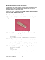
1
Myrinet-2000 Installation and
Troubleshooting Guide
Myricom, Inc.
Draft: 07 April 2007
The most recent version of this document can be downloaded from
http://www.myri.com/scs/doc/troubleshooting_guide.pdf
© 2007 Myricom, Inc. DRAFT
1
Table of Contents
I. Introduction .......................................................................................................................................... 3
II. What Hardware Is Required? ............................................................................................................... 3
III. Hardware Installation .......................................................................................................................... 3
IV. What Software Do I Need To Install? ............................................................................................... 12
V. MX-2G Software Installation .............................................................................................................. 13
1. Configuring and compiling MX-2G. ................................................................................................. 13
2. Installing the MX-2G mcp and driver. ............................................................................................. 14
3. Enabling IP over Myrinet (Ethernet emulation) (OPTIONAL)...................................................... 18
VI. GM-2 Software Installation................................................................................................................ 18
1. Configuring and compiling GM-2..................................................................................................... 18
2. Installing the GM-2 driver................................................................................................................. 19
3. Enabling IP over Myrinet (Ethernet emulation) (OPTIONAL)...................................................... 22
VII. GM-1 Software Installation .............................................................................................................. 23
1. Configuring and compiling GM-1..................................................................................................... 23
2. Installing the GM-1 driver................................................................................................................. 23
3. Run the GM-1 mapper ....................................................................................................................... 25
4. Enabling IP over Myrinet (Ethernet emulation) (OPTIONAL)...................................................... 27
VIII. Testing/Validation............................................................................................................................ 28
2. Run fm_switch to ensure that the FMS database includes all switches ......................................... 28
3. Run fm_db2wirelist to look for any missing hosts.......................................................................... 29
4. Check the LEDs on each switch port and NIC port ....................................................................... 29
5. Test performance between each host and NIC ............................................................................... 30
7. Run mpi_stress or gm_stress to stress all of the connections in the Myrinet fabric ..................... 31
8. Run fm_show_alerts for diagnostic information on any damaged/failing hardware component.32
Appendix A: Determining if a Problem is Hardware or Software Related........................................... 33
Appendix B: Isolating the Cause of a Hardware Problem...................................................................... 37
B.1. How do I determine if a cable has failed? .................................................................................... 39
B.2. How do I determine if a port on a switch line card has failed?.................................................. 39
B.3. How do I determine if a Myrinet NIC has failed?....................................................................... 40
Appendix C: Troubleshooting Performance ............................................................................................ 42
© 2007 Myricom, Inc. DRAFT
2
I.
Introduction
This Myrinet-2000 Installation and Troubleshooting Guide describes the hardware and
software installation procedures for a Myrinet-2000 cluster. Section II summarizes the
required hardware, and Section III provides detailed installation instructions for each
hardware component. Sections IV, V, VI, and VII address the software installation of
MX, GM-2, or GM-1, and Section VIII describes the testing and validation of the
Myrinet cluster. Appendices A and B provide diagnostics for determining if a problem
is hardware- or software-related, as well as procedures for isolating the source of a
hardware failure. Appendix C details troubleshooting procedures for performance
abnormalities.
II. What Hardware Is Required?
A Myrinet-2000 network consists of the following hardware components connected to
your host computers.
Myrinet-2000 PCI-X or PCI64 Network Interface Cards (NICs)
Myrinet-2000 M3-E* or M3-CLOS-ENCL-*/M3-SPINE-ENCL-* Switch(es)
Myrinet-2000 Fiber cables
The basic requirements are:
NICs:
Switches:
Cables:
one per host
at least one port per host (more required for clusters larger than
128 hosts when using M3-E* switches, or if using PCI-X NICs
with multiple ports).
one per port on each NIC (connecting to a port on a switch), plus
any required between switches.
Detailed Myrinet-2000 product specifications are available:
http://www.myri.com/myrinet/product_list.html
III. Hardware Installation
Upon receipt of the Myrinet hardware, we recommend reading the following documents.
For Myrinet-2000 M3-E* switches, please read:
© 2007 Myricom, Inc. DRAFT
3
"Guide to Switches and Switch Networks”
http://www.myri.com/myrinet/m3switch/guide/
For Myrinet-2000 M3-CLOS-ENCL-* or M3-SPINE-ENCL-* switches, please read:
http://www.myri.com/myrinet/14U_switches/
http://www.myri.com/scs/14U_switches/
and the following section of the Myrinet FAQ (http://www.myri.com/cgibin/fom?file=369.
For Myrinet-2000 PCIX-based NICs, we recommend reading:
“Guide to Myrinet PCI-X Network Interface Cards”
http://www.myri.com/scs/doc/guide_to_pcix_nics.pdf
For Myrinet-2000 PCI64-based NICs, we recommend reading:
“Guide to Myrinet/PCI Host Interfaces”
http://www.myri.com/scs/doc/guide_to_interfaces.pdf
After reading these guides, you should be aware of the following important information
and precautions pertaining to Myrinet PCI-X and PCI NICs:
•
•
•
•
•
Myrinet-2000 PCI-X NICs support both PCI-X and PCI protocols, and can be used
in any 3.3V PCI slot.
Myrinet-2000 PCI NICs function correctly in hosts with 32-bit or 64-bit PCI slots,
with either a 33MHz or 66MHz PCI clock, and with either 3.3V or 5V signaling.
Myrinet-2000 PCI NICs function correctly in PCI-X slots, except for the PCI-X
slots in some AMD64, EM64T, and PowerPC64 motherboards. Contact
[email protected] for further details.
If at all possible, avoid the use of riser cards with Myrinet PCI or PCI-X NICs.
We recommend that the Myrinet-2000 PCI (or PCI-X) NIC is installed into the PCI
(or PCI-X) slot closest to the PCI chipset.
After reading the "Guide to Switches and Switch Networks", you should be aware of the
following important information and precautions pertaining to Myrinet-2000 M3-E*
switches:
© 2007 Myricom, Inc. DRAFT
4
•
•
•
•
•
•
If your Myrinet-2000 M3-E* switch is equipped with a monitoring line card
(located in the top-slot of the switch), this monitoring line card contains 10base-T
dual ethernet ports and DHCP is required for its installation.
A Myrinet-2000 switch does not require any configuration.
Switch line cards (M3-SW16-8E, M3-SW16-8F, M3-SPINE-8F, M3-BLANK) are
hot-swappable.
A line card, a fan tray, or an enclosure is a Field Replaceable Unit (FRU). The
power supply is not an FRU; it is built into the enclosure.
We recommend the use of dust plugs in unused ports on the switch, and require
blank panels in unused slots (for cooling and EMI reasons).
You must provide proper ventilation for the switch(es), otherwise shutdown due to
overheating could occur.
After reading the documentation on the Myrinet-2000 Switches for Large Clusters, you
should be aware of the following important information and precautions pertaining to
M3-CLOS-ENCL-* and M3-SPINE-ENCL-* switches:
•
•
•
•
•
•
Each M3-CLOS-ENCL-* and M3-SPINE-ENC-*L switch is equipped with a
monitoring line card (located in the left-most-slot of the switch), and this
monitoring line card contains 10/100base-T dual ethernet ports. Assigning a static
IP address or DHCP is required for its installation.
A Myrinet-2000 M3-CLOS-ENCL-* or M3-SPINE-ENCL-* switch does not require
any configuration.
For the M3-SPINE-ENCL-* enclosure, the M3-THRU-16Q switch line cards must
be inserted in odd-numbered slots of the enclosure, and the M3-4SW32-16Q switch
line cards must be inserted in the even-numbered slots of the enclosure.
For the M3-CLOS-ENCL-* enclosure, if there are M3-THRU-16Q and M3-4SW3216Q switch line cards in the middle slots (slots 8-11), the M3-THRU-16Q switch
line cards must be in slots 8 and 9, and the M3-4SW32-16Q switch line cards in
slots 10 and 11.
Switch line cards (M3-SW32-16F, M3-2SW32, M3-4SW32-16Q, M3-THRU-16Q,
M3-AIRDAM) are hot-swappable.
The M3-CLOS-ENCL (or M3-SPINE-ENCL) enclosure contains four 350W power
supplies that can be individually hot-swapped, and operate in an auto-parallel
mode in which any three power supplies are sufficient to supply the maximum
power a unit may require.
© 2007 Myricom, Inc. DRAFT
5
•
•
•
•
•
The M3-CLOS-ENCL-B (or M3-SPINE-ENCL-B) enclosure contains two 840W
power supplies that can be individually hot-swapped, and operate in an autoparallel mode in which any one power supply is sufficient to supply the maximum
power a unit may require.
Two fan assemblies are included in each M3-CLOS-ENCL-* and M3-SPINEENCL-* enclosure, and they can be individually hot-swapped.
The line cards, the power supplies, and the fan assemblies, are Field Replaceable
Units (FRU).
We recommend the use of dust plugs in unused ports on the switch, and require
blank panels (M3-AIRDAM) in unused slots (for cooling and EMI reasons).
You must provide proper ventilation for the switch(es), otherwise shutdown due to
overheating could occur.
After reading these guides, you should be aware of the following important information
and precautions pertaining to Myrinet-2000 cables:
•
•
•
•
•
•
•
•
Fiber-cable ends and ports on line cards must be kept free of dust particles.
Accumulation of dust can cause faults from the port-to-fiber connection.
Myrinet-2000 fiber cables are 50/125 multimode fiber pairs with LC connectors.
Myricom does not guarantee correct operation with other than 50/125 fiber cables.
Myrinet-2000 quad-link ribbon fiber cables for inter-switch connections on the M3CLOS-ENCL and M3-SPINE-ENCL enclosures are industry-standard cables with
MTP/MPO fiber connectors on each end.
Myrinet-2000 cables are hot-pluggable.
Myrinet-2000 fiber cables should be disconnected by carefully depressing the
connector tab, otherwise damage can result.
Myrinet-2000 quad-link ribbon fiber cables should be disconnected by pulling back
the beige sleeve/latch on the black connector. No force whatsoever should be
applied to the cable itself.
Avoid crimping cables (bending at tight angles) as damage can result. The
minimum bend radius for fiber cables is a "finger width" (or 1/4" radius).
You should provide support restraints for cabling of large cluster configurations.
E.g.,
•
http://www.phys.lsu.edu/faculty/tohline/capital/beowulf.html
© 2007 Myricom, Inc. DRAFT
6
•
http://helics.iwr.uni-heidelberg.de/gallery/index.html
Installation of the Myrinet PCI-X/PCI Network Interface Cards (NICs)
Following the installation instructions in the “Guide to Myrinet PCI-X Network Interface
Cards” or the “Guide to Myrinet/PCI Host Interfaces” document, you will perform the
following steps:
1. Install the Myrinet NIC(s) into your host(s).
2. Power on the host(s).
3. Detect the NIC(s) in your host(s) using the Linux command /sbin/lspci. (If
you are using an operating system other than Linux, appropriate detection
commands are listed in the aforementioned documents.)
We assume that the operating system has already been installed on the host(s), and riser
cards are installed if needed.
Caution: If at all possible, avoid the use of riser cards. Riser cards can be a
significant source of problems in a hardware configuration. Although PCI riser
cards are commonly used, they will generally violate PCI specifications for the
length of signal traces. A riser card may also introduce impedance
discontinuities and signal degradation between the motherboard, riser card, and
NIC. If you observe PCI-communication errors when using a riser card, refer to
the diagnostic procedure below. A higher quality riser card – one whose traces
match the impedance of signals on the motherboard and NIC – may also solve the
problem.
It is important that a 64-bit riser card is used in a 64-bit PCI slot, and likewise a
32-bit riser card is used in a 32-bit PCI slot. If you are using a riser card with
multiple slots, the Myrinet NIC should be placed in the slot closest to the PCI
connector on the motherboard to minimize the distance between the PCI
connector on the motherboard and the PCI connector on the riser card.
Otherwise, the Myrinet PCI NIC may not be correctly detected and/or serious
performance irregularities will result.
If a Myrinet NIC is not detected using /sbin/lspci, then
•
•
•
•
•
•
Are you using a riser card?
Is the NIC properly seated in the PCI slot or riser card?
Have you tried cleaning the gold edge fingers of the PCI connector on the
Myrinet NIC and reinserting the NIC into the PCI slot?
Have you tried inserting the NIC into a different slot on the riser card?
Have you tried inserting the NIC directly into the PCI slot?
Have you tried using a different PCI slot?
© 2007 Myricom, Inc. DRAFT
7
•
•
Have you tried using a different riser card and/or a different brand of riser
card?
Have you tried using a newer BIOS for this motherboard?
Installation of the Myrinet switch and cables
Once the Myrinet NIC(s) have been installed and correctly detected in your host(s), you
can now proceed to install the switch(es) and connect the cables. Separate instructions
are included below for M3-E* Switches and M3-CLOS-ENCL or M3-SPINE-ENCL
Switches.
M3-E* Switches
The installation of the M3-E* switch and cables involves the following steps:
1. Plug in the power cord of the switch and verify that all of the switch line cards
are properly seated. If a switch line card is properly seated, you will see the
Status LED, located on the far left of each front panel, illuminated. If your
switch contains a monitoring line card, do not yet seat the monitoring line card
or connect ethernet to the monitoring line card. Installation of the monitoring
line card will be performed after all of the fiber cables have been connected.
2. A cable should then be connected between the fiber port on each NIC and a
port on a switch line card.
If more than one Myrinet switch is being used in your configuration, refer
to the provided network diagram for cabling details.
If you have M3F2-PCIXE NICs, you can connect both ports of each NIC
to one switch or to different switches in a dual-rail configuration. Refer to
the FAQ entry http://www.myri.com/cgi-bin/fom?file=326 for details.
If you have M3-SW16-8E GbE switch line cards, refer to the FAQ entry
"Are there any special installation instructions for the M3-SW16-8E GbE
switch line cards?" (http://www.myri.com/cgi-bin/fom?file=357) for
installation troubleshooting details.
3. You should next install the monitoring line card (located in the top-slot) in the
switch. The presence of a monitoring line card in the switch is optional. If
your switch does not contain a monitoring line card, you can skip this step of
the hardware installation. To install a monitoring line card in your Myrinet2000 switch, do the following:
Step 1. Read the MAC address from the faceplate of the monitoring line
card, and register this MAC address with a static IP address in the
reservation table of the DHCP server on the local network. The DHCP
© 2007 Myricom, Inc. DRAFT
8
server will then serve this static IP address to the monitoring line card
when it boots and asks for it. On Linux, this file is /etc/dhcpd.conf.
The MAC address is a group of 6 hexadecimal numbers separated by
colons, and should begin with 00:60:dd:??:??:??.
Step 2. Before seating the monitoring line card into the top slot of the
Myrinet-2000 switch, connect at least the first ethernet port to the LAN.
For high availability, the second ethernet port can also be connected.
The monitoring line card can ONLY be installed in the top slot of your
Myrinet-2000 switch.
The ethernet ports on the monitoring line card are 10base-T.
Step 3. When the monitoring line card is locked in position, a green LED
for the line card and the LEDs for the connected ethernet port(s) will
illuminate. The monitoring line card will immediately start to broadcast
DHCP requests. When the monitoring line card has received its IP
address, it is reachable. You can ping the card or open a web browser to it.
To determine the IP address that was assigned to the monitoring line card,
look at the file /var/state/dhcp/dhcpd.leases on your DHCP server.
Each time a monitoring line card is powered on, it will ask for its IP
address (and netmask) via DHCP. You can specify a gateway with the
DHCP "routers" option. The lease time is 1 day.
To test that your monitoring line card is properly installed, you can ping its IP
address or open a web browser to its IP address. We suggest that you familiarize
yourself with the features of the HTTP interface to the monitoring line card, as
many of these features can be very useful diagnostic tools. A description of these
features can be found in the “Myrinet-2000 Switch Information” section of the
Myrinet FAQ (http://www.myri.com/scs/FAQ/).
If you have difficulties installing the monitoring line card, refer to the Myrinet
FAQ entry “How do I install the monitoring line card in my Myrinet-2000 M3-E*
switch?” (http://www.myri.com/cgi-bin/fom?file=200) and feel free to contact
[email protected] for assistance.
M3-CLOS-ENCL-* and M3-SPINE-ENCL-* Switches
The installation of the M3-CLOS-ENCL-* (or M3-SPINE-ENCL-*) switch and cables
involves the following steps:
© 2007 Myricom, Inc. DRAFT
9
1. Plug in the power cord of the switch and the color TFT display (driven by the
monitoring line card) will illuminate and exhibit a color-bar display. After the
operating system finishes to boot (about 10 seconds), the color-bar display
will change to a virtual image of the switch. Do not yet connect ethernet to
the monitoring line card (in the left-most slot of the switch chassis).
Configuration of the monitoring line card will be performed after all of the
fiber cables have been connected.
2. Verify that all of the switch line cards are properly seated. If a switch line
card is properly seated, you will see the Status LED, located on the top of
each front panel, illuminated in green.
3. A cable should then be connected between the fiber port on each NIC and a
port on an M3-SW32-16F switch line card on the M3-CLOS-ENCL
enclosure. Configurations of more than 256 hosts employ quad-link ribbonfiber cables for inter-switch connections.
If more than one Myrinet switch is being used in your configuration, refer
to the provided network diagram for cabling details.
If you have M3F2-PCIXE NICs, you can connect both ports of each NIC
to one switch or to different switches in a dual-rail configuration. Refer to
the FAQ entry http://www.myri.com/cgi-bin/fom?file=326 for details.
4. Configure the monitoring line card (located in the left-most-slot) in the switch
by assigning it an IP address statically or via DHCP.
To assign a static IP address to the monitoring line card:
Step 1: Does the TFT Display include the option net? If yes, proceed to
Step 2. Otherwise, you must connect the monitoring line card via DHCP
(see page 11) and upgrade the firmware to v0.9.8.8 or later and reboot.
Step 2: To use static IP addressing select net on the main TFT screen and
enter the IP address and netmask with the turn-push knob.
Step 3: Enable addressing by setting enabled to yes, and then click done.
Step 4: Connect at least one of the ethernet ports to the LAN. For high
availability, the second ethernet port can also be connected.
Note: The ethernet ports on the monitoring line card are 10/100-Base-T.
Step 5: Reboot the monitoring line card (or power cycle the switch).
When the monitoring card comes up again it will skip the DHCP step and
use the assigned IP address and netmask.
© 2007 Myricom, Inc. DRAFT
10
Step 6: As soon as the ethernet port is connected, the upper green LED on
the RJ45 connector will illuminate.
Step 7: When the monitoring line card has received its IP address, it is
reachable. You can ping the card, open a web browser to it, or walk the
SNMP MIB.
Step 8: If you make a mistake and cannot ping the switch, then use the
TFT display to turn static addressing to no and reboot.
To assign an IP address via DHCP:
Step 1. Read the MAC address from the faceplate of the monitoring line
card, and register this MAC address with a static IP address in the DHCP
server configuration file (/etc/dhcpd.conf) on the DHCP server on the
local network. The DHCP server will then serve this static IP address to
the monitoring line card when it boots and asks for it.
The MAC address is a group of 6 hexadecimal numbers separated by
colons, and should begin with 00:60:dd:??:??:??.
Step 2. Connect at least one of the ethernet ports on the monitoring line
card to the LAN. For high availability, the second ethernet port can also be
connected.
The ethernet ports on the monitoring line card are 10/100-Base-T.
Step 3. As soon as the ethernet port is connected, the upper green LED on
the RJ45 connector will illuminate, and the monitoring line card will
immediately start to broadcast DHCP requests. When the monitoring line
card has received its IP address, it is reachable. You can ping the card,
open a web browser to it, or walk the SNMP MIB.
Note: To determine the IP address that was assigned to the monitoring line
card, you can select big_uc from the color-TFT display, or Status->Slot
m from the web interface, or refer to the file /var/state/dhcp/dhcpd.leases
on your DHCP server.
The DHCP client (udhcp) on the monitoring line card does not ask for any
particular lease time. It will accept whatever lease the DHCP server gives
it, and only attempt to renew the lease after reaching half the life of the
lease.
For further details of the SNMP interface, refer to "Does the monitoring
line card in the M3-CLOS-ENCL-* and M3-SPINE-ENCL-* switches
support SNMP?" (http://www.myri.com/cgi-bin/fom?file=383).
© 2007 Myricom, Inc. DRAFT
11
Each time a monitoring line card is powered on, it will ask for its IP
address (and netmask) via DHCP. You can specify a gateway with the
DHCP "routers" option.
To test that the monitoring line card is properly configured, you can ping its IP
address or open a web browser to its IP address. We suggest that you familiarize
yourself with the features of the HTTP interface to the monitoring line card, as
many of these features can be very useful diagnostic tools. A web interface
tutorial can be found at http://www.myri.com/scs/14U_switches/.
If you have difficulties configuring the monitoring line card, refer to the Myrinet
FAQ entry “How do I configure the monitoring line card in my M3-CLOS-ENCL* and/or M3-SPINE-ENCL-* switch?” (http://www.myri.com/cgibin/fom?file=374). Feel free to contact [email protected] for assistance.
IV. What Software Do I Need To Install?
Myricom supplies and supports Myrinet software (low-level firmware and middleware)
for a variety of operating systems and processors. All Myricom-supported software
requires a login/password for download. The login/password must be obtained from
Myricom Technical Support, [email protected], via the webpage
http://www.myri.com/scs/loginrequest.html.
There are two choices for low-level firmware: MX or GM. For middleware, the
following APIs are available: MPI, VIA, PVM, Sockets (SDP), and DAPL.
Performance graphs for Myricom-supported software are available:
http://www.myri.com/scs/performance/
The first Myrinet software package you must install is the low-level firmware: MX or
GM. The low-level firmware includes a driver, Myrinet-NIC control program, a network
mapping program, and the API, library, and header files.
•
•
•
MX-2G is supported on Myrinet-2000 PCIX-based NICs.
GM-2 is supported on Myrinet-2000 PCIX-based and PCI64-based NICs.
GM-1 is supported on Myrinet-2000 PCI64-based and PCI32-based NICs.
MX is the next generation of Myrinet software and firmware following GM-2.
Myricom's Myrinet software support has always spanned two generations of Myrinet
NICs. GM-2 was released in May 2003 together with the first of the PCI-X series of
Myrinet NICs, but GM-2 was already backported to operate also with the previous PCI64
series NICs. MX-10G is supported on Myri-10G NICs, and MX-2G is supported on the
PCI-X series of Myrinet NICs. MX-2G and MX-10G are fully compatible at the API and
application levels.
© 2007 Myricom, Inc. DRAFT
12
MX-2G or GM-2 software is required for use with the Myrinet-2000 M3-CLOS-ENCL-*
and M3-SPINE-ENCL-* switches. MX-2G and GM 2.1.x support multi-path, dispersive
routing, a technique that improves the utilization of the network bisection in large
networks.
GM-2 software is required for ethernet-emulation interoperability with M3-SW16-8E
switch line cards. MX-2G does not provide support for the M3-SW16-8E switch line
cards. If you are using GM-2, GM-2.1.x software is required in order to use both ports of
the two-port M3F2-PCIXE NICs.
For the purposes of this document, we shall only discuss a software installation on the
Linux operating system. Similar installation instructions exist for all of the other
supported operating systems and can be found on their respective OS-specific download
page (accessible via http://www.myri.com/scs/).
V. MX-2G Software Installation
MX-2G installation is performed in three easy steps:
1. Configuring and compiling MX-2G.
2. Installing the MX-2G mcp and driver.
3. Enabling IP over Myrinet (ethernet emulation) (OPTIONAL)
For detailed installation instructions for MX with FMS diagnostic monitoring, refer to the
FMS webpage (http://www.myri.com/scs/fms/#install-mx).
The following installation instructions assume that your cluster is not diskless. If you
have a diskless cluster, please contact [email protected] for the proper installation
procedure. We currently recommend MX-2G 1.1.6. For full details, please refer to
http://www.myri.com/scs/#downloads. After you have completed these installation steps,
proceed to Section VIII. Testing/Validation (page 27).
1. Configuring and compiling MX-2G.
Download MX-2G
http://www.myri.com/ftp/pub/MX/mx2g_1.1.6.tar.gz
gunzip -c mx2g_1.1.6.tar.gz | tar xvf cd mx-1.1.6
./configure
make
By default, we assume that the header and config files of your Linux kernel (required to
compile outside modules and either part of a kernel-headers or kernel-source package
depending on your distribution) are pointed by /lib/modules/`uname -r`/{source,build}.
If your Linux installation is not standard, or you are cross-compiling for a kernel different
from the one of the compile node you must configure with the following option:
© 2007 Myricom, Inc. DRAFT
13
$ ./configure --with-linux=<linux-source-dir>
where <linux-source-dir> specifies the directory for the Linux kernel source. The kernel
header files MUST match the running kernel exactly: not only should they both be from
the same version, but they should also contain the same kernel configuration options.
Note:
•
For Linux 2.6 kernels, the kernel headers/scripts often come in two parts in two
different directories, you might need to use both --with-linux and --with-linuxbuild. For instance to select a specific kernel, you might need something like:
$ ./configure --with-linux=/usr/src/linux-2.6.5-7.151/ \
--with-linux-build=/usr/src/linux-2.6.5-7.151-obj/x86_64/smp/
•
By default, the mapper in MX is provided by the Fabric Management System
(FMS).
If you would like to use the diagnostic capabilities of FMS, you need to specify
the name of the FMS server (the node on which the fms process will be run) at
configure time, using --with-fms-server=<fms_server>.
$ ./configure --with-fms-server=<fms_server>
To defer this specification until install time, or to override it, you may install MX
with make install FMS_SERVER=<fms_server>.
For detailed installation instructions for MX with FMS diagnostic monitoring,
refer to the FMS webpage.
•
If you would like to use the previous mapper, mx_mapper, you need to configure
with the option --disable-fms.
2. Installing the MX-2G mcp and driver.
Select an installation directory path <install_path>. It is usually best for <install_path>
to be the path to an NFS directory available on all machines that are to share this MX
installation. The directory must be accessible using <install_path> on all machines that
are to share the installation. <install_path> must be an absolute path; it must start with /.
However, <install_path> may contain symbolic links.
Note: The <install_path> installation directory must be created prior to invoking the
make install script.
make install DESTDIR=<install_path>
If you omit DESTDIR=<install_path>, the mcp and driver will be installed in the
directory specified with the configure --prefix option, or the default directory, /opt/mx/.
The MX binaries are located in <install_path>/bin and <install_path>/sbin. The 32-bit
© 2007 Myricom, Inc. DRAFT
14
MX libraries are installed in <install_path>/lib32 and the 64-bit MX libraries are
installed in <install_path>/lib64. The <install_path>/lib directory is a symbolic link to
either lib64 or lib32 depending on the native wordsize detected by configure. E.g., on
most ppc64 distributions, gcc defaults to 32-bit, which means that lib links to lib32.
However, on most x86_64 distributions, gcc defaults to 64-bit, so lib links to lib64.
Unless specified on the configure line, MX builds 32-bit libraries on 32-bit architectures
(i386, ppc) and 64-bit libraries on 64-bit architectures (ia64, AMD64, ppc64). It is
possible to build both by using the --enable-32b and --enable-64b configure flags.
Next, you must run
su root
<install_path>/sbin/mx_local_install
<install_path>/sbin/mx_start_stop start
echo <install_path>/lib32 >> /etc/ld.so.conf
echo <install_path>/lib64 >> /etc/ld.so.conf
echo <install_path>/lib >> /etc/ld.so.conf && /sbin/ldconfig
on each machine to perform local install steps, to load the modules, and to start a mapper
for each Myrinet NIC contained in the machine. If applicable, the mx_start_stop script
is also available in /etc/init.d/mx. The ldconfig line is optional, and adds the MX library
directory to the system library search path. If you do not do this, individual users will
need to either manage their LD_LIBRARY_PATH environment variable or link their
programs with an -rpath option for the dynamic linker to locate the MX shared library.
When the hardware is connected through a cable to another operating component and the
MX-2G firmware has been loaded, a green “link” LED and a yellow/amber “Lanai” LED
will illuminate on NICs and a green “link” LED will illuminate on connected ports on the
line cards (on the TFT display). If you do not see a green “link” LED illuminated on a
component (port on a NIC or port on a switch line card), refer to the following
diagnostics:
•
•
•
•
•
•
If you do not see any green “link” LEDs illuminated, is the switch powered
on?
If you do not see green “link” LEDs illuminated on only a specific line card, is
the line card properly seated in the enclosure? (Refer to the “Guide to
Switches and Switch Networks” for the proper procedure to insert/remove a
line card.)
If you do not see a green “link” LED on a specific port on a NIC or port on a
line card, is the port connected by a cable to another component?
If a NIC port does not have a green link LED illuminated, is its host powered
on?
Have you tried disconnecting and reconnecting the cable at both ends (at the
NIC port and the port on the line card)?
Have you tried a different cable or a different port on the line card?
© 2007 Myricom, Inc. DRAFT
15
The yellow "Lanai" LED is controlled by the Lanai processor, and will pulse like a
heartbeat while the MCP/firmware is running. If an error occurs, the yellow "Lanai"
LED will pulse an S.O.S signal. If the yellow LED is not pulsing, the MX-2G MCP is
not loaded or is not running.
Refer to the FAQ entry "How can I tell if the MX Mapper has correctly detected all of the
hosts in my Myrinet network?" (http://www.myri.com/cgi-bin/fom?file=427).
If you have tried all of these procedures and you cannot resolve the problem, contact
[email protected] for assistance. You cannot continue with the software installation until
this issue is resolved.
Further Details
The make install script copies the MX binaries to the specified binary installation
directory <install_path>.
The mx_local_install script performs the following operations:
•
•
•
Copies other files from the binary installation directory to an architecturespecific directory (/etc/init.d/).
Creates the devices (/dev/mx* and /dev/mxp*), one device per NIC
Creates the mapper’s per-host configuration directory (/var/run/fms/) and
possibly stores configuration files there.
The mx_start_stop “start” script performs the following operations:
•
•
•
•
Stops any Ethernet-over-Myrinet devices (myri*)
Unloads any currently loaded MX or GM driver (using rmmod)
Loads the MX mcp and driver modules (using insmod)
Starts a mapper daemon called mx_mapper for each Myrinet NIC contained in
the machine. The PIDs of the running mx_mappers are stored in
/var/run/mx_mapper/pid.{board_id}, and the map files are stored in
/var/run/mx_mapper/map.{board_id}.
Important note: The MX start script does not configure the IP device. If you wish to
run IP over MX/Myrinet (ethernet emulation), you must configure the device. (Refer to
Step 3 of the installation process.)
If you wish to have the driver auto-load at boot, you must create appropriate links in the
/etc/rcN directories to the /etc/init.d/mx script, or, for example, use the following
command (for Debian Linux):
update-rc.d mx defaults
© 2007 Myricom, Inc. DRAFT
16
or (for RedHat Linux):
chkconfig –add mx
Alternatively, you may start and stop the driver manually using
su root
/etc/init.d/mx start
/etc/init.d/mx stop
or
su root
/etc/init.d/mx restart
The mx “stop” script performs the following operations:
•
•
•
Shuts down the mx_mapper daemon
ifconfig’s down the myri* ethernet devices
Unloads the MX modules (using rmmod)
The mx "restart" script performs an mx stop followed by an mx start.
Note:
1. Legacy PCI64-based and PCI32-based Myrinet NICs are not supported.
2. MX must be compiled with the system compiler (gcc for Linux, Mac OS X, and
FreeBSD). We do not support third-party compilers.
3. If you are installing MX on Linux, you must configure/compile/load MX on a Linux
box whose running kernel is configured to match the source kernel tree. Note that
some Linux distributions ship a mismatched source kernel tree.
4. For optimal performance of MX on i386 and x86_64 hosts, write-combining must be
enabled on the PCI chipset. Refer to the MX README for details.
5. For application or middleware developers who need to develop code using the MX
API, refer to the MX API manual (http://www.myri.com/scs/MX/doc/mx.pdf).
6. If a host is rebooted, you must reload the MX drivers.
The most common /etc/init.d/mx start failures are:
•
•
•
APIC IRQ conflicts (encountered on several Tyan and AMD motherboards)
Running kernel / source kernel mismatch
Defective or inadequate riser cards
The solutions for these problems are summarized in the Myrinet FAQ
(http://www.myri.com/scs/FAQ/).
Undoubtedly, if you encounter an issue on a specific motherboard or version of Linux,
someone else has too, and it will be documented on the Myricom web site. If not, contact
us at [email protected].
© 2007 Myricom, Inc. DRAFT
17
3. Enabling IP over Myrinet (Ethernet emulation) (OPTIONAL)
If you wish to run IP over Myrinet (ethernet emulation), the Linux command to enable IP
over MX is as follows:
/sbin/ifconfig myri0 <ip_address> up
where you must replace myri0 with the appropriate name (myri1, myri2, etc.) if you have
more than one Myrinet NIC per host.
VI. GM-2 Software Installation
GM-2 installation is performed in three easy steps:
1. Configuring and compiling GM-2.
2. Installing the GM-2 driver.
3. Enabling IP over Myrinet (ethernet emulation) (OPTIONAL)
For detailed installation instructions for GM-2 with FMS diagnostic monitoring, refer to
the FMS webpage (http://www.myri.com/scs/fms/#install-tarball).
These installation instructions assume that your cluster is not diskless. If you have a
diskless cluster, please contact [email protected] for the proper installation procedure. We
currently recommend GM-2.0.26_Linux for clusters with PCIXD or PCIXF NICs, and
GM-2.1.26_Linux for clusters with PCIXE NICs. For full details, please refer to
http://www.myri.com/scs/#downloads. For purposes of this document, we will only
discuss the installation of GM-2.0.26_Linux. The installation of GM-2.1.26_Linux
follows the same procedure. After you have completed these installation steps, proceed to
Section VII. Testing/Validation (page 27).
1. Configuring and compiling GM-2.
Download GM-2
http://www.myri.com/ftp/pub/GM/gm-2.0.26_Linux.tar.gz
gunzip -c gm-2.0.26_Linux.tar.gz | tar xvf cd gm-2.0.26_Linux
./configure --with-linux=<linux-source-dir>
make
where <linux-source-dir> specifies the directory for the Linux kernel source. Note that
as of GM-2.0.15 and later, if the --with-linux= option is not specified, the default is
"/lib/modules/`uname -r`/build". This is the default location used by all major
distributions. The default in previous releases of GM was /usr/src/linux/.
© 2007 Myricom, Inc. DRAFT
18
If you would like to have FMS diagnostic monitoring with GM-2, refer to the FMS
Download page (http://www.myri.com/scs/fms/) for installation instuctions.
If you are building GM-2 on SuSE SLES9 on PowerPC64 or AMD64 or EM64T, you
may need to explicitly point configure at the kernel source and object trees. For example,
./configure --with-linux=/lib/modules/`uname -r`/source --withlinux-build=/lib/modules/`uname -r`/build
For more details on building GM-2 on AMD64 or EM64T, refer to "How do I build GM2 on AMD64 or EM64T?" (http://www.myri.com/cgi-bin/fom?file=252).
For more details on building GM-2 on PowerPC64, refer to "How do I build GM-2 on
PowerPC64?" (http://www.myri.com/cgi-bin/fom?file=260).
2. Installing the GM-2 driver.
Select an installation directory path <install_path>. It is usually best for <install_path>
to be the path to an NFS directory available on all machines that are to share this GM
installation. The directory must be accessible using <install_path> on all machines that
are to share the installation. <install_path> must be an absolute path; it must start with /.
However, <install_path> may contain symbolic links.
Note: The <install_path> installation directory must be created prior to invoking the
GM_INSTALL script.
cd binary
./GM_INSTALL <install_path>
If you omit <install_path>, the driver will be installed in the default directory, /opt/gm/.
Next, you must run
su root
<install_path>/sbin/gm_install_drivers
/etc/init.d/gm start
echo <install_path>/lib64 >> /etc/ld.so.conf
echo <install_path>/lib >> /etc/ld.so.conf && /sbin/ldconfig
on each machine.
When the hardware is connected through a cable to another operating component and the
GM-2 firmware has been loaded, a green “link” LED and a yellow/amber “Lanai” LED
will illuminate on NICs and a green “link” LED will illuminate on connected ports on the
line cards (on the TFT display). If you do not see a green “link” LED illuminated on a
component (port on a NIC or port on a switch line card), refer to the following
diagnostics:
© 2007 Myricom, Inc. DRAFT
19
•
•
•
•
•
•
If you do not see any green “link” LEDs illuminated, is the switch powered
on?
If you do not see green “link” LEDs illuminated on only a specific line card, is
the line card properly seated in the enclosure? (Refer to the “Guide to
Switches and Switch Networks” for the proper procedure to insert/remove a
line card.)
If you do not see a green “link” LED on a specific port on a NIC or port on a
line card, is the port connected by a cable to another component?
If a NIC port does not have a green link LED illuminated, is its host powered
on?
Have you tried disconnecting and reconnecting the cable at both ends (at the
NIC port and the port on the line card)?
Have you tried a different cable or a different port on the line card?
The yellow "Lanai" LED is controlled by the Lanai processor, and will pulse like a
heartbeat while the MCP/firmware is running. If an error occurs, the yellow "Lanai"
LED will pulse an S.O.S signal. If the yellow LED is not pulsing, the GM-2 MCP is not
loaded or is not running.
If you have tried all of these procedures and you cannot resolve the problem, contact
[email protected] for assistance. You cannot continue with the software installation until
this issue is resolved.
Further Details
The GM_INSTALL script copies the GM binaries to the specified binary installation
directory <install_path>.
The gm_install_drivers script performs the following operations:
•
•
•
•
•
Copies gm.o into /lib/modules/<KERNEL-VERSION>/gm/gm.o
Removes the previous installation by executing /sbin/gm_uninstall_drivers
(using rmmod)
Copies other files from the binary installation directory to an architecturespecific directory (/etc/init.d/).
Creates the devices (/dev/gm* and /dev/gmp*), one device per NIC
Creates the mapper’s per-host configuration directory (/etc/gm_mapper) and
possibly stores configuration files there.
The gm “start” script performs the following operations:
•
•
Loads the GM module (using insmod)
Starts a mapper daemon called gm_mapper for each Myrinet NIC contained in
the machine. The PIDs of the running gm_mappers are stored in
© 2007 Myricom, Inc. DRAFT
20
/var/run/gm_mapper/pid.{board_id}, and the map files are stored in
/var/run/gm_mapper/map.{board_id}.
Further details about the mapper in GM-2 can be found on the following
webpage:
http://www.myri.com/scs/mapper_gm2.html
Refer to the FAQ entry "How can I tell if the GM-2 Mapper has correctly
detected all of the hosts in my Myrinet network?" (http://www.myri.com/cgibin/fom?file=273).
Important note: Stopping the gm_mapper while GM-2 is running is not supported. The
gm_mapper should be left running at all times, and it will not interfere with the
performance of jobs running over Myrinet.
Important note: The gm start script does not configure the IP device. If you wish to run
IP over GM/Myrinet (ethernet emulation), you must configure the device. (Refer to Step
3 of the installation process.)
The ldconfig line in the installation process is optional, and adds the GM library
directory to the system library search path. If you do not do this, individual users will
have to either manage their LD_LIBRARY_PATH environment variable or link their
programs with an -rpath= option for the dynamic linker to locate the GM shared library.
If you wish to have the driver auto-load at boot, you must create appropriate links in the
/etc/rcN directories to the /etc/init.d/gm script, or, for example, use the following
command (for Debian Linux):
update-rc.d gm defaults
or (for RedHat Linux):
chkconfig –add gm
Alternatively, you may start and stop the driver manually using
su root
/etc/init.d/gm start
/etc/init.d/gm stop
or
su root
/etc/init.d/gm restart
The gm “stop” script performs the following operations:
© 2007 Myricom, Inc. DRAFT
21
•
•
•
Shuts down the gm_mapper daemon
ifconfig’s down the myri* ethernet devices
Unloads the GM module (using rmmod)
The gm "restart" script performs a gm stop followed by a gm start.
Note:
1. GM is not in the critical performance path so it does not need to be built with
specialized compilers and flags. GM should be built with Gnu gcc and only built with
-O level of optimization.
2. GM should be installed in an NFS-mounted area.
3. gm_install_drivers and /etc/init.d/gm start need to be run on all nodes in the
cluster!
4. The kernel header files MUST match the running kernel exactly: not only should they
both be from the same version, but they should also contain the same kernel
configuration options. (Be careful with RedHat kernel packages.)
5. By default, we assume that you have PCIXE, PCIXF, PCIXD, PCI64C, PCI64B, or
PCI64 NICs. (PCI32 NICs are not supported in GM-2.)
6. If a host is rebooted, you must reload the GM-2 driver.
The most common /etc/init.d/gm start failures are:
•
•
•
•
APIC IRQ conflicts (encountered on several Tyan and AMD motherboards)
Running kernel / source kernel mismatch
AGP (nVidia, ATI) conflicts
Defective or inadequate riser cards
The solutions for these problems are summarized in the FAQ entry “GM Installation
fails. What does this error message mean?” (http://www.myri.com/cgi-bin/fom?file=46).
Undoubtedly, if you encounter an issue on a specific mother board or version of Linux,
someone else has too, and it will be documented on the Myricom web site. If not, contact
us at [email protected].
3. Enabling IP over Myrinet (Ethernet emulation) (OPTIONAL)
If you wish to run IP over Myrinet (ethernet emulation), the Linux command to enable IP
over GM is as follows:
/sbin/ifconfig myri0 <ip_address> up
where you must replace myri0 with the appropriate name (myri1, myri2, etc.) if you have
more than one Myrinet NIC per host.
Note that GM-2 yields better IP performance over Myrinet than GM-1.
© 2007 Myricom, Inc. DRAFT
22
VII. GM-1 Software Installation
GM-1 installation is performed in four easy steps:
1.
2.
3.
4.
Configuring and compiling GM-1.
Installing the GM-1 driver.
Running the GM-1 mapper.
Enabling IP over Myrinet (ethernet emulation) (OPTIONAL)
For detailed installation instructions for GM-1 with FMS diagnostic monitoring, refer to
the FMS webpage (http://www.myri.com/scs/fms/#install-tarball).
After you have completed these steps, proceed to Section VII. Testing/Validation (page
27).
1. Configuring and compiling GM-1.
Download GM-1
http://www.myri.com/ftp/pub/GM/gm-1.6.7_Linux.tar.gz
gunzip -c gm-1.6.7_Linux.tar.gz | tar xvf cd gm-1.6.7_Linux
./configure --with-linux=<linux-source-dir>
where <linux-source-dir> specifies the directory for the Linux kernel source.
make
If you would like to have FMS diagnostic monitoring with GM-1, refer to the FMS
Download page (http://www.myri.com/scs/fms/) for installation instuctions.
2. Installing the GM-1 driver.
Select an installation directory path <install_path>. It is usually best for <install_path>
to be the path to an NFS directory available on all machines that are to share this GM
installation. The directory must be accessible using <install_path> on all machines that
are to share the installation. <install_path> must be an absolute path; it must start with /.
However, <install_path> may contain symbolic links.
Note: The <install_path> installation directory must be created prior to invoking the
GM_INSTALL script.
cd binary
./GM_INSTALL <install_path>
If you omit <install_path>, the driver will be installed in the default directory, /opt/gm/.
Next, you must run
su root
© 2007 Myricom, Inc. DRAFT
23
<install_path>/sbin/gm_install_drivers
/etc/init.d/gm start
on each machine to install/copy the driver on that machine.
When the hardware is connected through a cable to another operating component and the
GM-1 firmware has been loaded, a green “link” LED and a yellow/amber “Lanai” LED
will illuminate on NICs and a green “link” LED will illuminate on connected ports on the
line cards. If you do not see a green “link” LED illuminated on a component (port on a
NIC or port on a switch line card), refer to the following diagnostics:
•
•
•
•
•
•
If you do not see any green “link” LEDs illuminated, is the switch powered
on?
If you do not see green “link” LEDs illuminated on only a specific line card, is
the line card properly seated in the enclosure? (Refer to the “Guide to
Switches and Switch Networks” for the proper procedure to insert/remove a
line card.)
If you do not see a green “link” LED on a specific port on a NIC or port on a
line card, is the port connected by a cable to another component?
If a NIC port does not have a green link LED illuminated, is its host powered
on?
Have you tried disconnecting and reconnecting the cable at both ends (at the
NIC port and the port on the line card)?
Have you tried a different cable or a different port on the line card?
The yellow "Lanai" LED is controlled by the Lanai processor, and will pulse like a
heartbeat while the GM MCP/firmware is running, and will pulse faster when there is
more packet-sending activity (including sending acknowledge packets in reply to packets
received.) If the yellow LED is not pulsing, the GM MCP is not loaded or is not running.
If you have tried all of these procedures and you cannot resolve the problem, contact
[email protected] for assistance. You cannot continue with the software installation until
this issue is resolved.
Further Details
The gm_install_drivers script performs the following operations:
•
•
•
•
Shuts down existing IP over Myrinet
Unloads existing GM module (if it exists)
Creates the devices (/dev/gm* and /dev/gmp*), one device per NIC
Loads the GM module (insmod)
Important note: The /etc/init.d/gm start script does not configure the IP device. If you
wish to run IP over GM/Myrinet (ethernet emulation), you must configure the device.
(Refer to Step 4 of the installation process.)
© 2007 Myricom, Inc. DRAFT
24
If you wish the driver to auto-load at boot, you must create appropriate links in the
/etc/rcN directories to the /etc/init.d/gm script. Alternatively, you may start and stop the
driver manually using
su root
/etc/init.d/gm start
/etc/init.d/gm stop
or
su root
/etc/init.d/gm restart
Note:
1.
2.
3.
4.
5.
6.
GM is not in the critical performance path so it does not need to be built with
specialized compilers and flags. GM should be built with Gnu gcc and only built
with -O level of optimization.
GM should be installed in an NFS-mounted area.
gm_install_drivers and /etc/init.d/gm start need to be run on all nodes in the
cluster!
The kernel header files MUST match the running kernel exactly: not only should
they both be from the same version, but they should also contain the same kernel
configuration options. (Be careful with RedHat kernel packages.)
By default, we also assume that you have PCI64, PCI64A, PCI64B, or PCI64C
NICs. (PCI32 NICs are not supported in gm-1.6.3 and later.)
If a host is rebooted, you must reload the GM driver (and rerun the GM mapper).
The most common gm_install_drivers failures are:
•
•
•
•
APIC IRQ conflicts (encountered on several Tyan and AMD motherboards)
Running kernel / source kernel mismatch (commonly encountered with
RedHat kernel packages)
AGP (nVidia, ATI) conflicts
Defective or inadequate riser cards
The solutions for these problems are summarized in the FAQ entry “GM Installation
fails. What does this error message mean?”.
Undoubtedly, if you encounter an issue on a specific motherboard or version of Linux,
someone else has too, and it will be documented on the Myricom web site. If not, contact
us at [email protected].
3. Run the GM-1 mapper
cd <install_path>/sbin/
su root
./mapper ../etc/gm/map_once.args
© 2007 Myricom, Inc. DRAFT
25
Important points to note:
• The GM-1 mapper is ONLY run on one node in the cluster. You should
choose one node in the cluster to be the mapper node, and any subsequent
invocations of the mapper should be done on this node only.
• The GM-1 mapper must be run before any communication over Myrinet can
occur.
• If a host is rebooted, you must reload the GM driver and rerun the GM-1
mapper.
• If any topological change occurs in the cluster, the GM-1 mapper must be
rerun.
• Never run the GM-1 mapper on multiple nodes at the same time, as serious
routing confusion will result.
The aforementioned mapping procedure uses the most common form of mapping: “Map
Once” Mapping. Depending upon your needs, there are three ways to run the GM
mapper:
•
•
•
Map Once Mapping
Static or “File” Mapping
High Availability (HA) Mapping
“Map Once” Mapping is by far the most common way of running the GM mapper. In
this method, the mapper is run on one host in the network (any of the hosts). It is rerun if
a host (re)boots or a hostname is changed or after a change of Myrinet topology
(swapping of ports on a switch). The command for this method of running the GM
mapper is:
cd <install_path>/sbin/
su root
./mapper ../etc/gm/map_once.args
“Static” Mapping is another way in which the GM mapper may be used. In this method,
an active mapper is run once when ALL of the hosts are up and running the GM driver.
•
•
•
This initial active mapper will generate a map file and a host file.
These files are then shared by NFS, or copied to all of the hosts in the
network.
An entry in the boot scripts will allow each host to read the map file and the
host file and update the routing table on its local Myrinet NIC(s).
The command for this method of running the GM-1 mapper is:
cd <install_path>/sbin/
su root
./mapper ../etc/gm/static.args
© 2007 Myricom, Inc. DRAFT
26
If the GM tree is not mounted by NFS, copy the 3 files created by this command
(static.map, static.routes, and static.hosts) to each <install_path>/sbin/ directory
on each host.
For auto-mapping at boot time, add the following command to the boot scripts of
the host (scripts in /etc/init.d or /etc/rc.d/init.d).
cd <install_path>/sbin/
su root
./file_mapper ../etc/gm/file.args
“High Availability” Mapping is the third way in which the GM mapper may be used.
This method is for users who have a need for High Availability (HA) in an aggressive
computing environment. The command for this method of running the GM mapper is:
cd <install_path>/sbin/
su root
./mapper ../etc/gm/active.args &
“High Availability” Mapping will continuously run the GM mapper in the background
to detect and add any new hosts or remove any non-responding hosts, to detect any
change of topology (change of slots in the switch, change of innerswitch topology), and
to periodically update the routing tables of the Myrinet cards (by default, every 30
seconds).
You should note that this HA mapping method is slightly intrusive. Since the GM
mapper uses unreliable messages that may be dropped in case of heavy contention, this
method of mapping can lead to hosts involved in a long computation being marked as
“non-responding” and removed from the routing tables because they are unreachable.
For the majority of users, the "map_once" GM-1 mapping method is sufficient. For the
users with more production-level constraints, the "static mapping" is the recommended
method. For fault-tolerant GM applications, the third method provides the best
alternative.
4. Enabling IP over Myrinet (Ethernet emulation) (OPTIONAL)
If you wish to run IP over Myrinet (ethernet emulation), the Linux command to enable IP
over GM is as follows:
/sbin/ifconfig myri0 <ip_address> up
where you must replace myri0 with the appropriate name (myri1, myri2, etc.) if you have
more than one Myrinet NIC per host.
To obtain good IP performance over Myrinet, we recommend the use of Linux 2.4. Note
that GM-2 yields better IP performance over Myrinet than GM-1.
© 2007 Myricom, Inc. DRAFT
27
VIII. Testing/Validation
Once the MX, GM-2, or GM-1 firmware is running on all hosts in the cluster, and all
host-to-switch and switch-to-switch cables have been connected, you are ready to verify
the health of all of the Myrinet hardware components in the Myrinet installation by
performing the following sequence of tests. The Fabric Management System (FMS) is the
recommended diagnostic tool for Myrinet-2000 networks. Requirements for the
installation of FMS are summarized on the FMS webpage
(http://www.myri.com/scs/fms/).
•
•
•
•
•
•
•
•
Run fm_status to check the current status of the FMS
Run fm_switch to ensure that the FMS database includes all switches
Run fm_db2wirelist to look for any missing hosts
Check the LEDs on each switch port and NIC port
Test performance between each host and NIC
Test performance between each host and the switch
Run mpi_stress to stress all of the connections in the fabric
Run fm_show_alerts for diagnostic information on any damaged/failing
hardware components
If FMS cannot be installed, refer to the diagnostic procedures in the “Troubleshooting”
section of the FAQ: http://www.myri.com/cgi-bin/fom?file=481.
These steps are detailed below and are also described in the “Troubleshooting” section of
the FAQ (http://www.myri.com/scs/FAQ/). Once you have performed these tests, you will
have a solid Myrinet installation.
1. Run fm_status to check the current status of the FMS.
$ fm_status
If you are using Myrinet-2000 M3-CLOS-ENCL or M3-SPINE-ENCL switches, it
should take less than 30 seconds to map the Myrinet fabric. If it takes longer, please
submit a bug report to [email protected].
If you are using Myrinet-2000 M3-E* switches, it may take up to five minutes to map the
Myrinet fabric. If it takes longer, please submit a bug report to [email protected].
2. Run fm_switch to ensure that the FMS database includes all switches
To view a list of all of the switch enclosures currently defined in the FMS database, type
$ fm_switch
If there are any switches missing from the database, add the missing switch to the
database by issuing the command
© 2007 Myricom, Inc. DRAFT
28
$ fm_switch -a <switch_name>
where <switch_name> is the DNS name or IP address for the monitoring line card in the
specific switch enclosure.
If you need to remove a switch from the database, run
$ fm_switch –d <switch_name>
If the monitoring line card has not yet been installed in the switch(es), refer to "How do I
install the monitoring line card in my Myrinet-2000 M3-E* switch?"
(http://www.myri.com/cgi-bin/fom?file=200) or "How do I configure the monitoring line card in
the M3-CLOS-ENCL-* and/or M3-SPINE-ENCL-* switch(es)? (http://www.myri.com/cgibin/fom?file=374).
3. Run fm_db2wirelist to look for any missing hosts
As soon as the FMS database has been created, we recommend running fm_db2wirelist
to print a list of all connections in the fabric.
$ fm_db2wirelist
fm_db2wirelist reads the database of connections and prints a list of the contents of each
switch's slots and connections. Reviewing this list is a good way to notice links that have
lost connectivity.
fm_db2wirelist [ -R <fms_run> ] [ -N <db_name> ]
If a known connected port is missing from the fm_db2wirelist output, refer to the
following quick-check list:
• Is the green LED illuminated on this port?
• Is the fiber cable securely attached at both ends?
• Is the MX/GM firmware properly installed and running on all nodes (check
/var/log/messages)?
• Is there an fma process running on all hosts in the network?
• Does the output of fm_status list all connected hosts, and does it list any alerts?
• If the missing connection is a host-to-switch connection, is this host listed in the
routing table output of mx_info or gm_board_info?
4. Check the LEDs on each switch port and NIC port
After the hardware installation and the MX or GM software installation have been
successfully completed, there will be a green LED illuminated on each switch port (on
the TFT display) for each connection that is active. If not, check the power supply to the
switch, and check that the Myrinet cable is securely attached both at the switch end and at
© 2007 Myricom, Inc. DRAFT
29
the other end. On the host, there will be a green LED illuminated and a flashing
yellow/amber LED illuminated on each NIC.
If the LED of a connected port is not illuminated in green, refer to "Run fm_db2wirelist
and look for any missing links". If FMS is not available, please consult the diagnostic
procedures in Appendix B "Isolating the Cause of a Hardware Problem".
If you're using an M3-CLOS-ENCL-* or M3-SPINE-ENCL-* switch, please consult the
following webpage (http://www.myri.com/scs/14U_switches/#tft-green) for guidelines in
troubleshooting a connected port whose LED is not illuminated in green or yellow/amber.
5. Test performance between each host and NIC
We recommend the following test to verify your MX performance.
cd <install_path>/bin
./mx_dmabench
This mx_dmabench test displays the results of the hardware benchmark test of the PCI
bus with the DMA engine of the Myrinet NIC. The output of this command indicates the
maximum sustained bandwidth that can be obtained from the PCI bus, and thus provides
an upper bound on MX performance.
We recommend the following test to verify your GM performance.
cd <install_path>/bin
./gm_debug –L
This gm_debug test displays the results of the hardware benchmark test of the PCI bus
with the DMA engine of the Myrinet NIC. The output of this command indicates the
maximum sustained bandwidth that can be obtained from the PCI bus, and thus provides
an upper bound on GM performance. A detailed description of this benchmark can be
found in the FAQ entry “Can you describe in detail the “hardware benchmark of the PCI
bus” that is returned by gm_debug?” (http://www.myri.com/cgi-bin/fom?file=121).
The output of these commands also tells you the PCI speed at which the Myrinet NIC is
running. If the PCI speed for the Myrinet NIC was not correctly detected by the BIOS,
refer to the following troubleshooting steps:
•
You should first refer to the hardware documentation for the motherboard.
There could be a jumper near the PCI slots that must be set to adjust the PCI speed.
Or, there could be another PCI device that is sharing the same PCI bus as the Myrinet
NIC, and the PCI bus has been slowed to the speed of the other PCI device. Refer to
the output of /sbin/lspci –tv or /sbin/lspci –vvv to determine if there are any PCI
devices sharing the same PCI bus.
© 2007 Myricom, Inc. DRAFT
30
If you must have two PCI devices sharing the same PCI bus, and both devices are
able to run at 133MHz, but the PCI bus is not running at 133MHz, are you sure that
the motherboard can sustain two PCI devices on the same PCI bus running at full
speed?
•
Or, if you are using a riser card, there could be a problem with the riser card. Not all
64-bit riser cards will run at 133MHz. Refer to the FAQ entry “My PCI-X slot should
run at 133MHz, but gm_debug reports 66MHz or 100MHz. What’s wrong?”
(http://www.myri.com/cgi-bin/fom?file=281). You should try using the Myrinet NIC
without the riser card and see if the NIC is correctly detected.
•
Or, you could need a BIOS update for your motherboard.
•
Or, there could be a PCI slot problem on the motherboard. You should try using a
different PCI slot.
Sample PCI Bus Performance for Myrinet/PCI-X NICs
(http://www.myri.com/scs/performance/PCIX_motherboards/) is available. Performance
measurements (http://www.myri.com/scs/performance/Myrinet-2000/) for MX and GM
are also available.
6. Test performance between each host and the switch
Run mx_pingpong with shared memory disabled on all nodes to check for consistent
unidirectional bandwidth performance.
export MX_DISABLE_SHMEM=1
export MX_RCACHE=1
mx_pingpong –e 0 –r 1 –S 0 –E 10000000 –M 1.7 &
mx_pingpong –e 1 –r 0 –S 0 –E 10000000 –M 1.7 –d ‘hostname’:0
On PCIXD and PCIXF NICs, the result should be very close to the 250 MB/s line rate
(~246 MB/s) and on PCIXE NICs, it should be very close to the 500 MB/s line rate.
7. Run mpi_stress or gm_stress to stress all of the connections in the Myrinet fabric
Two stress programs have been developed to “stress” all of the connections in the
Myrinet fabric. Note that these stress programs are NOT benchmarking programs for
performance. These stress programs are designed to flood the network with lots of sends
and receives among multiple hosts in order to isolate/emphasize any link that may have a
damaged cable or other damaged hardware component. These stress programs can be run
on a subset of nodes or the whole cluster.
One of the stress programs is an MPI program, mpi_stress.c, and is available in the MX
distribution. Configure, compile, and install MPICH-MX or MPICH-GM, and then use
© 2007 Myricom, Inc. DRAFT
31
mpicc to compile mx/unit_test/src/mpi/mpi_stress.c. The executable mpi_stress can
then be run like any other MPI program using mpirun.ch_mx or mpirun.ch_gm.
If the GM firmware is installed on the cluster, the GM-specific stress program,
gm_stress.c, can also be used to stress the network. Full details of how to run gm_stress
can be found on the FAQ entry (http://www.myri.com/cgi-bin/fom?file=53).
8. Run fm_show_alerts for diagnostic information on any damaged/failing hardware
component.
Are there any “un-ACKed alerts” listed in the output of fm_status?
If yes, run fm_show_alerts to print a list of all active alerts, signaling possible hardware
error conditions.
Alerts are created when certain exceptional events occur and are reported to the fms.
Alerts persist within the fms until they are cleared. Clearing usually requires the alert to
be acknowledged (ACKed) and for the condition which caused the alert to have cleared.
Once the alert has been acknowledged, it is marked as "ACKed". Once the condition that
caused the alert has cleared, we mark it as a "relic". Most alerts are deleted only after they
have been both relic-ed and ACKed.
By default, fm_show_alerts prints only alerts which have not been ACKed and are not
relics. Each alert has a unique index which can be passed to fm_ack_alert to
acknowledge the alert.
Refer to http://www.myri.com/scs/fms/#alerts as well as the file libfma/alert.def in the
FMS distribution, for a detailed listing of all possible alerts.
Example output of fm_show_alerts can also be found on the FMS webpage,
http://www.myri.com/scs/fms/#examples.
© 2007 Myricom, Inc. DRAFT
32
Appendix A: Determining if a Problem is Hardware or Software
Related
Diagnosing a problem as hardware- or software-related can be difficult. The first goal is
to isolate where the problem resides:
•
•
•
•
Host computer hardware (e.g., a bad PCI slot, defective or inadequate riser card,
buggy BIOS, etc)
Host computer software (e.g., OS not configured properly)
Myrinet hardware (NIC, switch, or cable)
Myrinet software (GM driver, GM mapper, MPICH-GM, etc)
Some of the key questions in isolating the cause of the problem are:
•
Did the procedures outlined in Section VIII Testing/Validation (page 27) yield
any errors?
•
If you installed FMS, did you see any alerts listed in the output of fm_status and
fm_show_alerts?
•
If you are unable to install FMS, do you see a high number of bad crcs (packetdata errors) reported in the host or switch counters? If you suspect a Myrinet
hardware problem, you need to examine these hardware counters. Of all of the
host counters, only bad crcs can indicate a potential hardware failure. A small
number of badcrcs is harmless. As the number of badcrcs increases, they can
lead to performance degradation, a loss of connectivity to a specific host, and
interference with the mapper's ability to map the network.
•
Do you see a high number of Bad CRC8 in the output of mx_counters or a
high number of badcrc_cnt in the output of gm_counters on any of the
nodes?
cd <install_path>/bin/
./mx_counters | grep "Bad CRC8"
cd <install_path>/bin/
./gm_counters | grep badcrc__invalid
If the value of badcrc__invalid is non-zero, it should be very small compared
to the value of netrecv_cnt (the total number of packets received).
For further details, refer to "How do I isolate the cause of a high Bad CRC8
count in mx_counters? (http://www.myri.com/cgi-bin/fom?file=423) and
"How do I isolate the cause of a high badcrc_cnt count in gm_counters?"
(http://www.myri.com/cgi-bin/fom?file=58).
© 2007 Myricom, Inc. DRAFT
33
•
Is there a monitoring line card installed in each Myrinet-2000 switch? If yes,
do you see a high number of bad crcs reported in the switch counters?
If you're using a Myrinet-2000 M3-E* switch, this information can be
obtained with the following command:
lynx –dump <switch_ip_address>/all | grep badCrcs
If you're using a Myrinet-2000 M3-CLOS-ENCL or M3-SPINE-ENCL
switch, this information can be obtained with the following command:
lynx –dump <switch_ip_address>/cgi/web.cgi\?all | grep badCrcs
•
Are there non-zero values of switch traps related to overheating, etc? Refer to
"What is the meaning of each of the trap counts reported by the Myrinet-2000
M3-E* switch?" (http://www.myri.com/cgi-bin/fom?file=206), and for the
Myrinet-2000 M3-CLOS-ENCL/M3-SPINE-ENCL switches, refer to the Switch
Tutorial (http://www.myri.com/scs/14U_switches/).
•
If you installed FMS, does the output of fm_status list all nodes, and does it say
that the network is fully configured?
•
If you are unable to install FMS, does the output of mx_info or gm_board_info
list all nodes in the routing table, and say that the Myrinet network is fully
configured? If one of the nodes is missing from the routing/mapping table, refer
to the diagnostic procedures in "How can I tell if the MX Mapper has correctly
detected all of the hosts in my Myrinet network?" (http://www.myri.com/cgibin/fom?file=427), or "How can I tell if the GM-2 Mapper has correctly detected
all of the hosts in my Myrinet network?" (http://www.myri.com/cgibin/fom?file=273), or "How can I tell if the GM-1 Mapper has correctly detected
all of the hosts in my Myrinet network?" (http://www.myri.com/cgibin/fom?file=127).
If you are using the Myrinet-2000 M3-CLOS-ENCL and M3-SPINE-ENCL
switches, and a particular switch port is unable to communicate, is the switch port
reported as out-of-sync (http://www.myri.com/scs/14U_switches/index-overviewweb.html #sync)? Refer to "One of the connected switch ports is not illuminated
in green." (http://www.myri.com/scs/14U_switches/#tft-green) for full details.
•
Do all nodes report similar performance for mx_dmabench or gm_debug -L?
Refer to the subsection entitled “3. Run mx_dmabench or gm_debug to test the
PCI bandwidth” (page 31) in Section VIII Testing/Validation for a discussion of
diagnostic procedures to isolate the cause of an inconsistency.
© 2007 Myricom, Inc. DRAFT
34
•
Did the firmware (MX or GM) load properly on all nodes in the cluster? Were
there any error messages in the system log (dmesg or /var/log/messages) output
on any of the nodes when you loaded the firmware? Sections V, VI, and VII
address software installation and troubleshooting issues. Run-time diagnostic
error messages are also explained in the Myrinet FAQ
(http://www.myri.com/scs/FAQ/).
•
Were there any error messages in the system log (dmesg or /var/log/messages)
output on any of the nodes after loading the firmware?
•
Were there software run-time error messages while running the application? A
number of these run-time messages are explained in the Myrinet FAQ
(http://www.myri.com/scs/FAQ/).
Further Details
If there are host computer hardware or software problems, these problems will most
likely be encountered as a failure during the Myrinet hardware or software installation
phase (Section III and Section VIII Testing/Validation). Or, these types of problems
may also be exhibited/revealed as an unexplained performance degradation or
performance inconsistency on the nodes. Refer to the subsection entitled “3. Run
mx_dmabench or gm_debug to test the PCI bandwidth” (page 30) in Section VIII
Testing/Validation for further details.
If there are any faulty Myrinet hardware components, these components are most easily
isolated with the Fabric Management System (FMS) as described in Section VIII
Testing/Validation. If you are unable to install FMS, you can use the troubleshooting
procedures outlined in Appendix A and Appendix B.
There are two sources of hardware counters available for Myrinet:
• host counters, reported by the MX test program mx_counters or the GM test
program gm_counters; and
• switch counters and traps, reported by the web interface to the Myrinet switch(es).
These hardware counters reveal important information about the health of the Myrinet
hardware and the interactions of the hardware and the software. A detailed explanation
of each of these hardware counters can be found in the Myrinet FAQ
(http://www.myri.com/scs/FAQ/), and in the M3-CLOS-ENCL/M3-SPINE-ENCL switch
tutorial (http://www.myri.com/scs/14U_switches/). If you are using the M3-CLOSENCL/M3-SPINE-ENCL switches, you can use the Log feature of the web interface
(http://www.myri.com/scs/14U_switches/index-overview-web.html#log) to monitor
switch traps in real-time. If you are using the M3-E* switches, Mute
(http://www.myri.com/scs/mute/) can be used to monitor the switch traps in real time.
Note that Mute has been replaced by the Fabric Management System (FMS).
© 2007 Myricom, Inc. DRAFT
35
If you are using M3-E* switches, two other useful hardware counters for diagnosing
hardware failures are the switch counters called serdesFaultTrap and missedBeatTrap.
It is important to note that these two traps can be harmless and merely signal a port on a
switch line card that is unconnected. However, if the port generating these traps is
connected by a cable, then these traps indicate a port failure and the symptoms would be
a loss of connectivity to a specific host, usually accompanied by the lack of illumination
of the green LED associated with that port.
Have you run mpi_stress and/or gm_stress on the cluster?
The recommended Myrinet-2000 Diagnostic Tool is the Fabric Management System
(FMS) (http://www.myri.com/scs/fms/). FMS will work with either GM or MX on Myrinet2000 M3-E* or M3-CLOS-ENCL/M3-SPINE-ENCL switches.
If you are not able to install FMS on your cluster, then you need to follow the diagnostic
procedures described in Appendix B to isolate the malfunctioning hardware component.
If you suspect a Myrinet software problem, please check the Myrinet Software and
Customer Support webpage (http://www.myri.com/scs/) to see if there is a newer release, or
check the Myrinet FAQ (http://www.myri.com/scs/FAQ/) for any reports of known problems.
© 2007 Myricom, Inc. DRAFT
36
Appendix B: Isolating the Cause of a Hardware Problem
The following diagnostic procedures will need to be used if you are unable to install the
Fabric Management System (FMS).
Two of the most commonly reported hardware failures are damaged cables and damaged
port connectors.
As previously mentioned in Appendix A, a high badcrc count (reported in the host or
switch hardware counters) or a serdesFaultTrap for a connected port (reported in the
switch hardware counters) is a strong indication of hardware damage/failure. Our
guarantee is an *average* of less than 1 packet-data error (badcrc) per hour on a link
operating at full data rate. If you suspect a Myrinet hardware failure, this failure could be
in a Myrinet NIC, a cable, a port on a Myrinet switch, or within a Myrinet switch.
If the failure is in a combination of (NIC, cable from the NIC to the switch, or port on a
switch) it is possible to diagnose this situation quite easily using the mx_pingpong
"loopback test" or the gm_allsize "loopback test" as described below. However, if the
failure lies within a switch, or on a cable connecting two switches, the following
procedure will not detect this kind of failure. The diagnostic tool FMS is needed to detect
this type of switch-to-switch failure.
Note: If you are using a mixture of Myrinet-2000 and Myrinet-1280 hardware, badcrcs
will be generated if the switch line card or the NICs are set to different speeds. Some
products have a mechanical switch on the circuit board to allow the default data rate to be
switched between SAN-2000 (2.0+2.0 Gb/s) and SAN-1280 (1.28+1.28 Gb/s). Please
refer to the Myrinet FAQ entry “I have Myrinet-2000 NICs and Myrinet-1280 switches
and my NICs and switches aren’t able to talk to each other. What do I do?” for more
details on checking and setting the speed.
The mx_pingpong "loopback test" or gm_allsize "loopback test" limits all
communication to a specific Myrinet NIC, cable, and port on a Myrinet switch.
If you are using MX, the mx_pingpong "loopback test" is performed as follows:
1. Reset the host counters
cd <install_path>/bin/
su root
./mx_counters –c
2. On each node, run:
mx_counters | grep Bad
su root
© 2007 Myricom, Inc. DRAFT
37
mx_stop_mapper
mx_msg_loop -n
mx_counters | grep Bad
where <hostname> is the name of the host on which the test is being run.
Note that after running the test, the mx_mapper process must be restarted on the
host, as follows:
cd <install_path>/sbin/
su root
mx_start_mapper
If you’re using GM-2, the gm_allsize "loopback test" is performed as follows:
1. Reset the host counters
cd <install_path>/bin/
su root
./gm_counters –C
2. On each node, run:
./gm_counters | grep badcrc__invalid
su root
killall gm_mapper
./gm_simpleroute --disable-software-loopback
./gm_allsize --min-size=10 --max-size=20 --count-per-length=10
./gm_counters | grep badcrc__invalid
Note that after running the test, the gm_mapper process must be restarted on the
host.
If you’re using GM-1, the gm_allsize "loopback test" is performed as follows:
1. Reload the GM-1 module on all nodes (resets the host counters to zero)
su root
/etc/init.d/gm start
2. Rerun the GM-1 mapper.
3. On each node, run:
./gm_counters | grep badcrc_cnt
./gm_allsize --min-size=10 --max-size=20 --count-per-length=10
./gm_counters | grep badcrc_cnt
© 2007 Myricom, Inc. DRAFT
38
If the badcrc_cnt (reported in gm_counters) increased significantly after the test on any
of the hosts, then you have identified a possible hardware trouble spot in your cluster and
you must now isolate if the badcrc_cnt is coming from the Myrinet NIC, the cable, or
the port on the Myrinet switch.
B.1. How do I determine if a cable has failed?
In most cases, the Bad CRC8 or badcrc__invalid (or badcrc_cnt) is caused by a
damaged cable. As a first step, if you have some extra cables, we suggest that you first try
replacing the suspect cable, and then rerunning the above mx_pingpong
"loopback_test" or gm_allsize "loopback test" to see if the value of Bad CRC8 or
badcrc__invalid (or badcrc_cnt) continues to increase. If this does not eliminate the
badcrcs then the cable is not the cause of the hardware failure, and you must now
determine if the failure is due to the Myrinet NIC or the port on the Myrinet switch to
which it is connected.
If the Bad CRC8 or badcrc__invalid (or badcrc_cnt) does not increase after replacing
the cable, then you have isolated the damaged hardware component.
Contact [email protected] to return the cable for repair/replacement, and you will be
assigned a "Return Material Authorization" (RMA) number. The information required
for an RMA is outlined in the Myrinet FAQ (http://www.myri.com/scs/FAQ/).
B.2. How do I determine if a port on a switch line card has failed?
To determine if a port on a Myrinet switch has failed, do the following:
With a known good cable, try connecting the NIC port to a different port on the switch
line card, and rerun the mx_pingpong "loopback test" or gm_allsize "loopback test".
If the badcrc count no longer increases, then the old switch port is the cause of the
hardware failure. Please note that if a cable is moved from one switch port to another
switch port (or from one NIC to another NIC), the topology of the network has changed.
Each MX/GM process has a relative address to each other process (something like “go to
the first switch, jump 3 ports, go to the next switch, jump -2 ports”), and if the cabling of
the network has changed, then the mapper must be re-run so that these relative addresses
can be updated.
If you’re using MX or GM-2, this change in topology will be automatically detected by
the MX/GM-2 mapper. However, if you’re using GM-1, the GM-1 mapper must be rerun before any communication over the Myrinet network can occur.
If the port on a switch line card is identified as the point of failure, contact
[email protected] to return this switch line card for repair/replacement. You will be
assigned a "Return Material Authorization" (RMA) number. The information required for
an RMA is outlined in the Myrinet FAQ (http://www.myri.com/scs/FAQ/).
© 2007 Myricom, Inc. DRAFT
39
B.3. How do I determine if a Myrinet NIC has failed?
If exchanging the cable and the port on the switch line card do not eliminate the errors,
then the Myrinet NIC may be the point of failure. Here are some suggestions for
determining whether a Myrinet NIC has failed.
First, try using the NIC in isolation by running the mx_pingpong "hardware loopback
test" or gm_allsize "hardware loopback test".
The hardware loopback test is performed as follows:
1. Disconnect the standard Myrinet cable from the NIC and attach a fiber loopback
cable/plug.
M3F-L Fiber Loopback cable (plug)
2. If you're using MX, run the mx_pingpong "hardware loopback test" as follows:
mx_counters [-b <n>] | grep Bad
su root
mx_stop_mapper
env MX_DISABLE_SELF="1" MX_DISABLE_SHMEM="1" mx_pingpong [-b
<n>] -e 0 -r 1 &
env MX_DISABLE_SELF="1" MX_DISABLE_SHMEM="1" mx_pingpong [-b
<n>] -e 1 -r 0 -d <hostname>:0
mx_counters [-b <n>] | grep Bad
where <hostname> is the name of the host on which the test is being run, and the [-b
<n>] option is only necessary if the board number is other than 0.
3. If you're using GM-2, run the gm_allsize "hardware loopback test" as follows:
gm_counters [--board=n]
su root
killall gm_mapper
gm_simpleroute --disable-software-loopback [--board=n]
gm_allsize --geometric --exit-on-error [--board=n]
gm_counters [--board=n]
© 2007 Myricom, Inc. DRAFT
40
4. If you're using GM-1, run the gm_allsize "hardware loopback test" as follows:
gm_counters [--board=n]
gm_simpleroute --loopback [--board=n]
gm_allsize --geometric --exit-on-error [--board=n]
gm_counters [--board=n]
The --board flag is only necessary if the board number is other than 0.
If the hardware loopback test completed successfully, and the value for Bad CRC8
reported by mx_counters or badcrc__invalid or badcrc_cnt reported by gm_counters
did not increase significantly, then the Myrinet NIC is not the point of failure. The
problem may reside with the cable or the Myrinet switch port.
Note that after running gm_simpleroute, the GM-1 mapper must be re-run to restore the
routes to other nodes in the system. For GM-2, gm_simpleroute --enable-softwareloopback must be run before restarting the gm_mapper on the host.
If the foregoing procedure is not feasible, you can try installing the suspect NIC in
another PCI slot or in another host. Does the problem follow the suspect NIC? If you use
an alternative NIC, does the problem disappear?
If the questionable NIC fails in a PCI slot which is successful with another Myrinet NIC especially another NIC of the same class - then this NIC has probably failed.
If a NIC is identified as the point of failure, contact [email protected] to return this NIC
for repair/replacement. You will be assigned a "Return Material Authorization" (RMA)
number. The information required for an RMA is outlined in the Myrinet FAQ
(http://www.myri.com/scs/FAQ/).
© 2007 Myricom, Inc. DRAFT
41
Appendix C: Troubleshooting Performance
If you suspect a performance anomaly, we suggest:
1. Run mx_dmabench or gm_debug -L on each node in the cluster to ensure that
all nodes report consistent read/write performance and PCI speed.
2. If you are using the Fabric Management System (FMS), does fm_show_alerts
detect significant badcrcs in the fabric? Alternatively, check for badcrcs in the
mx_counters or gm_counters output, as well as the hardware counters on the
switch.
If you see a large numbers of badcrcs (hundreds, thousands), then you may have a
failing hardware component (cable, port on switch, or port on NIC) that needs to
isolated and replaced.
3. Run mx_pingpong or gm_allsize to test performance.
Is the performance comparable to that reported on the Myrinet Performance
webpage (http://www.myri.com/scs/performance/Myrinet-2000/)?
The test program mx_pingpong can be run to test the MX PingPong latency and
unidirectional bandwidth between two hosts. Adding the -V flag to the
mx_pingpong command will augment the test with verification of the contents of
all messages, at the cost of significantly degraded performance. For a list of all
options to mx_pingpong, type mx_pingpong -help.
Latency and Unidirectional Bandwidth
To test the MX PingPong latency and unidirectional bandwidth between two
hosts (host1 and host2), type the following on host1:
mx_pingpong
and on host2 type:
mx_pingpong -d host1:0
The output from this command will consist of three columns of data: the first
column lists the message size (in bytes), the second column lists the latency (in
microseconds), and the third column lists the unidirectional bandwidth (in MB/s).
Similarly, the test program gm_allsize can be used to measure the GM latency
and bandwidth. Adding the --verify flag to any gm_allsize command will
augment the test with verification of the contents of all messages, at the cost of
© 2007 Myricom, Inc. DRAFT
42
significantly degraded performance. For a list of all options to gm_allsize, type
gm_allsize –help or refer to the FAQ. For sample output of gm_allsize,
refer to the FAQ entry “What are the run-time options to gm_allsize?”
(http://www.myri.com/cgi-bin/fom?file=79).
Latency
To test the GM latency between two hosts (host1 and host2), type the following
on host1:
gm_allsize –slave
and on host2 type:
gm_allsize --remote-host=host1 --geometric
The output from this command will consist of two columns of data: the first
column lists the message size (in bytes), and the second column lists the latency
(in microseconds).
Unidirectional Bandwidth
To test the unidirectional bandwidth between two hosts (host1 and host2), type
the following on host1:
gm_allsize --slave --size=15
and on host2 type:
gm_allsize --unidirectional --bandwidth \
--remote-host=host1 --size=15 --geometric
where the length of the messages sent is 2**(size - 8) bytes. Unidirectional
bandwidth is a PingPing test, measuring the startup and throughput of a single
message sent between two processes, where messages are obstructed by
oncoming messages.
The output from this command will consist of two columns of data: the first
column lists the message size (in bytes) and the second column lists the
bandwidth (in MB/s).
Bidirectional (Summed) Bandwidth
To test the bidirectional (summed) bandwidth between two hosts (host1 and
host2), type the following on host1:
gm_allsize --slave --size=15
© 2007 Myricom, Inc. DRAFT
43
and on host2 type:
gm_allsize --both-ways --bandwidth \
--remote-host=host1 --size=15 –geometric
where the length of the messages sent is 2**(size - 8) bytes. This test has GM
streaming packets in both directions (both nodes are always sending) and it causes
GM to report the sum of the send and receive bandwidths.
The output from this command will consist of two columns of data: the first
column lists the message size (in bytes) and the second column lists the
bandwidth (in MB/s).
4. Run a sample benchmark (e.g., HPL) (1 node run) on each of the nodes in the
cluster to ensure that all nodes report consistent performance. If not, there could
be an issue with a particular CPU on one of the hosts.
5. Run a sample benchmark (e.g., HPL) on equally-sized subsets of nodes. Make
sure that performance is consistent across all subsets of nodes. If you see a
particular subset that is slower, then you need to perform a divide-and-conquer
approach to isolate the slower node.
© 2007 Myricom, Inc. DRAFT
44