1
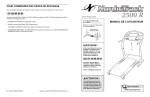
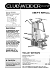
Model No. PFCCEX37082
Serial No.
USER’S MANUAL
Write the serial number in the
space above for reference.
Serial
Number
Decal
If you require SERVICE for
this product, please call
SEARS:
1-800-4 MY HOME
(469-4663)
If you are MISSING PARTS or
require INFORMATION on how
to operate this product, call
1-888-936-ICON
(4266)
CAUTION
Read all precautions and instructions in this manual before using
this equipment. Save this manual
for future reference.
Notre site internet
www.proform.com
TABLE OF CONTENTS
IMPORTANT PRECAUTIONS . . . . . . . . . . . . . . . . . . . . . . . . . . . . . . . . . . . . . . . . . . . . . . . . . . . . . . . . . . . . .2
BEFORE YOU BEGIN . . . . . . . . . . . . . . . . . . . . . . . . . . . . . . . . . . . . . . . . . . . . . . . . . . . . . . . . . . . . . . . . . . .3
PART IDENTIFICATION CHART . . . . . . . . . . . . . . . . . . . . . . . . . . . . . . . . . . . . . . . . . . . . . . . . . . . . . . . . . . .4
ASSEMBLY . . . . . . . . . . . . . . . . . . . . . . . . . . . . . . . . . . . . . . . . . . . . . . . . . . . . . . . . . . . . . . . . . . . . . . . . . . .5
HOW TO USE THE PROFORM® REBEL . . . . . . . . . . . . . . . . . . . . . . . . . . . . . . . . . . . . . . . . . . . . . . . . . . . . .8
MAINTENANCE AND TROUBLESHOOTING . . . . . . . . . . . . . . . . . . . . . . . . . . . . . . . . . . . . . . . . . . . . . . . . .10
CONDITIONING GUIDELINES . . . . . . . . . . . . . . . . . . . . . . . . . . . . . . . . . . . . . . . . . . . . . . . . . . . . . . . . . . . .12
PART LIST . . . . . . . . . . . . . . . . . . . . . . . . . . . . . . . . . . . . . . . . . . . . . . . . . . . . . . . . . . . . . . . . . . . . . . . . . . .14
EXPLODED DRAWING . . . . . . . . . . . . . . . . . . . . . . . . . . . . . . . . . . . . . . . . . . . . . . . . . . . . . . . . . . . . . . . . .15
ORDERING REPLACEMENT PARTS . . . . . . . . . . . . . . . . . . . . . . . . . . . . . . . . . . . . . . . . . . . . . . . .Back Cover
LIMITED WARRANTY . . . . . . . . . . . . . . . . . . . . . . . . . . . . . . . . . . . . . . . . . . . . . . . . . . . . . . . . . . .Back Cover
IMPORTANT PRECAUTIONS
WARNING: To reduce the risk of serious injury, read the following important precautions before using the PROFORM® REBEL Recumbent Cycle and Elliptical Crosstrainer.
1. Read all instructions in this manual before
using the REBEL.
using the REBEL. Always wear athletic
shoes for foot protection.
2. It is the responsibility of the owner to
ensure that all users of the REBEL are adequately informed of all precautions.
8. Always hold the handlebars when mounting,
dismounting, or using the REBEL. Step onto
and off the pedal that is in the lowest position when mounting or dismounting.
3. Place the REBEL on a level surface, with a
mat beneath it to protect the floor or
carpet. Keep the REBEL indoors, away from
moisture and dust.
9. When you stop exercising, allow the pedals
to slowly come to a stop. The REBEL does
not have a free wheel; the pedals will continue to move until the flywheel stops.
4. Inspect and properly tighten all parts regularly. Replace any worn parts immediately.
10. Keep your back straight when using the
REBEL; do not arch your back.
5. Keep children under the age of 12 and pets
away from the REBEL at all times.
11. If you feel pain or dizziness while exercising, stop immediately and cool down.
6. The REBEL should not be used by
persons weighing more than 115 kg.
12. The REBEL is intended for in-home use
only. Do not use it in any commercial, rental,
or institutional setting.
7. Wear appropriate exercise clothing when
WARNING:
Before beginning this or any exercise program, consult your physician.
This is especially important for persons over the age of 35 or persons with pre-existing health
problems. Read all instructions before using. ICON assumes no responsibility for personal injury
or property damage sustained by or through the use of this product.
PROFORM is a registered trademark of ICON Health & Fitness, Inc.
2
BEFORE YOU BEGIN
Congratulations for selecting the revolutionary PROFORM® REBEL Recumbent Bike and Elliptical
Crosstrainer. The REBEL is an incredibly smooth
exerciser that moves your feet in a natural elliptical
path, minimizing the impact on your knees and ankles.
And the unique REBEL can easily be converted from
an elliptical crosstrainer to a recumbent bike, giving you
two machines in one. Welcome to a whole new world
of natural, elliptical-motion exercise from PROFORM.
ing this manual, please call our Customer Service
Department toll-free at 1-888-936-4266, Monday
through Friday, 8h00 until 18h00 Eastern Time
(excluding holidays). To help us assist you, please
note the product model number and serial number
before calling. The model number is PFCCEX37082.
The serial number can be found on a decal attached
to the REBEL (see the front cover of this manual).
Before reading further, please familiarize yourself with
the parts that are labeled in the drawing below.
For your benefit, read this manual carefully before
you use the REBEL. If you have questions after read-
Console
Book Holder and Seat
Handlebar
FRONT
Backrest
Lock Knob
(on back)
Upright
Resistance Knob
Side Shield
Base
Pedal
BACK
Toe Pedal
Pedal Leg
3
RIGHT SIDE
PART IDENTIFICATION CHART
Use the chart below to identify the small parts used in
assembly. The number in parenthesis below each part
is the key number of the part, from the PART LIST on
page 14. The number after the dash indicates the
quantity needed for assembly. Note: Some small
parts may have been pre-attached for shipping. If
a part is not in the parts bag, check to see if it has
been pre-attached.
M10 Nylon Locknut (54)–6
1/2" Nylon Locknut (9)–2
M10 Washer (71)–6
Metal Handlebar
Spacer (83)–2
Pedal Arm Spacer (42)–2
M16 Flat Washer (84)–2
Plastic Sleeve (53)–2
Pedal Bolt (8)–2
M4 x 38mm Screw (4)–2
M10 x 68mm Bolt (67)–4
M4 x 16mm Tapping
Screw (30)–8
M10 x 75mm Bolt (66)–2
Handlebar Screw (51)–4
Console Mount
Screw (69)–1
M6 x 16mm Seat Screw (28)–8
4
M10 x 25mm Button Head
Bolt (85)–2
ASSEMBLY
Assembly requires two persons. Place all parts of the PROFORM® REBEL in a cleared area and remove the
packing materials. Do not dispose of the packing materials until assembly is completed.
Assembly requires a phillips screwdriver
, two adjustable wrenches
rubber mallet
(none of these is included).
1. Hold the Stabilizer (68) against the saddle on the rear
of the Base (1). Attach the Stabilizer with two M10 x
75mm Bolts (66) and two M10 Nylon Locknuts (54).
, and a
54
1
1
54
68
66
2. Slide the “U”-channel on the Rail Stabilizer (37) into
the Base (1). Make sure that the Reed Switch Wire
(48) is extending from the hole formed where the
two parts meet; be careful not to damage the Reed
Switch Wire.
2
37
“U”-channel
Insert two M10 x 68mm Bolts (67) with two M10
Washers (71) up through the Base (1) and the Rail
Stabilizer (37). Note: It may be easier to insert the
Bolts if the unit is tipped on its side.
48
71
Insert two M10 x 68mm Bolts (67) with two M10
Washers (71) up through the Rail Stabilizer (37).
67
3. While one person holds the Upright (2), connect the
Extension Wire (49) to the Reed Switch Wire (48)
extending from the Base (1). Insert any excess wire
into the Upright or the Base.
3
1
54
54
Slide the Upright (2) onto the four M10 x 68mm Bolts
(67). Make sure that the wires do not get pinched
as you slide the Upright into place.
2
49
Hand tighten an M10 Nylon Locknut (54) onto each
M10 x 68mm Bolt (67). Tip the unit onto its side and
use two spanners to tighten the Nylon Locknuts fully.
48
67
5
1
4. Connect the Seat Bar Wire (88) to the Handlebar Wire
(87).
4
7
Slide the Handlebar (7) onto the Seat Bar (6). Attach
the Handlebar with the four Handlebar Screws (51).
Make sure that the Handlebar Screws do not damage
the wires.
Pull both Grips (72) towards the Handlebar (7) until
they cover the Handlebar Screws (51).
72
51
87
88
6
51
72
5. Remove the Console Mount Screw (69) and slide the
Detent Ring (73) off the shaft of the Console (5).
5
69
Console
Wire
Insert the console wire through the indicated hole in
the Seat Bar (6).
6
88
Using the included grease pack, lubricate the shaft of
the Console (5). Insert the shaft into the indicated hole
in the Seat Bar (6).
Slide the Detent Ring (73) onto the console shaft and
line up the hole in the Detent Ring with the hole in the
shaft. Secure the Console (5) with the Console Mount
Screw (69) (see the inset drawing).
73
69
Lubricate
Plug the console wire into the Seat Bar Wire (16).
73
5
6. Attach the Seat (43) to the indicated brackets on the
Seat Bar (6) with four M6 x 16mm Seat Screws (28).
6
Attach the Seat Cover (35) to the Seat (43), using two
M4 x 38mm Screws (4) along the rear edge and an M4
x 16mm Tapping Screw (30) on each side.
43
6
28
4
28
30
4
30
6
35
7. Note: The assistance of another person is recommended for this step.
7
7
While another person holds the Handlebar (7) in the
position shown, connect the Handlebar Wire (87) to
the Extension Wire (49) extending from the Upright (2).
Bracket
87
83
53
Next, slide a Plastic Sleeve (53) onto each of the indicated shafts on the Upright (2).
49
Slide an M10 Washer (71) onto each of the M10 x
25mm Button Head Bolts (85). Next, insert the Bolts
through the brackets on the Handlebar (7) and then
slide an M16 Flat Washer (84) and a Metal Handlebar
Spacer (83) onto each Bolt. Insert the Bolts into the
shafts on the Upright (2) and tighten them with the
included allen wrench. Be careful not to overtighten
the Bolts; the Handlebar must pivot easily.
85
71
84
2
84
85
83
53
Shaft
71
8
8. Attach the Backrest (40) to the indicated brackets on
the Upright (2) with four M6 x 16mm Seat Screws (28).
40
28
2
28
9. Identify the Left Pedal Leg (3) by looking at the
Lock Pin (90) on the pre-assembled Toe Pedal (36).
The Lock Pin must be on the outside when the
Pedal Leg is mounted.
9
Attach a Pedal (29) to the Left Pedal Leg (3) with three
M4 x 16mm Tapping Screws (30).
Lubricate a Pedal Bolt (8) with the included grease
pack and slide it through the two pre-assembled
Bushings (39). Slide a Plastic Pedal Spacer (42) onto
the Pedal Bolt (8) and slide the Bolt into the hole in the
left Crank Arm (10). Tighten a 1/2” Nylon Locknut (9)
onto the Pedal Bolt (8).
Repeat this procedure for the Right Pedal Leg (70, not
shown).
9
3
36
29
30
90
39
42
10
8
7
Lubricate
10.The Console (5) requires two “AA” batteries (not
included). Alkaline batteries are recommended.
10
To install batteries, first slide up the battery cover and
carefully remove the battery clip from the Console (5).
Insert two batteries into the battery clip as shown.
Make sure that the negative ends of the batteries
(marked “–”) are touching the springs in the battery clip. Replace the battery clip and close the battery cover.
Battery
Cover
Battery
Clip
5
11. Make sure that all parts of the REBEL are properly tightened. To protect the floor or carpet from damage,
place a mat under the REBEL.
HOW TO USE THE PROFORM® REBEL
HOW TO SWITCH BETWEEN RECUMBENT BIKE
AND ELLIPTICAL CROSSTRAINER
To switch from elliptical crosstrainer to recumbent
bike, loosen the Lock Knob (81, not visible). Fold the
Seat (43) down and turn the Console (5) so it is visible when you are sitting on the Seat.
To switch from recumbent bike to elliptical crosstrainer, lift the Seat (43) as far as it will go. Tighten the
Lock Knob (81, not visible) into the Upright (2). Note:
Tighten the Lock Knob fully. Push the Console (5)
in to disengage the lock, and then turn it so the display is visible when you are standing on the pedals.
HOW TO EXERCISE ON THE REBEL WHEN IT IS
SET UP AS AN ELLIPTICAL CROSSTRAINER
To mount the REBEL in the crosstrainer mode, hold
the handlebars and step onto the pedal that is in the
lowest position. Next, step onto the other pedal. Push
the pedals until they begin to move with a continuous
motion. Note: The crank can turn in either direction. To get the full impact of the elliptical motion,
it is recommended that you turn the crank in the
direction shown by the arrow below; however, to
give variety to your exercise, you may choose to
turn the crank in the opposite direction.
Lock Knob
5
Pedal
43
2
Crank
8
To dismount the REBEL, allow the pedals to slowly
come to a stop. Important: The REBEL does not
have a free wheel; the pedals will continue to
move until the flywheel stops. When the pedals are
stationary, step off the highest pedal first. Then, step
off the lowest pedal.
Display
HOW TO ADJUST THE TOE PEDALS
To adjust the Right Toe Pedal (89), pull out the Lock
Pin (90). Slide the Toe Pedal forward or backward to
the desired position. Insert the Lock Pin through the
holes in the Toe Pedal and the adjustment holes in
the Pedal Leg (70). Adjust the Left Toe Pedal (36, not
shown) in the same manner.
Speed—This mode displays your pedaling speed, in
miles per hour.
Time—This mode displays the elapsed time. Note:
When you stop exercising, the time mode will pause.
Distance—This mode displays the total distance you
have pedaled, in miles.
70
Fat Calorie—This mode displays the approximate
number of fat calories you have burned (see BURNING FAT on page 12).
89
90
Calorie—This mode displays the approximate number
of Calories you have burned.
Scan—This mode displays the speed, time, distance,
fat calorie, and calorie modes, for 5 seconds each, in
a repeating cycle.
HOW TO ADJUST THE RESISTANCE OF THE
PEDALS
As you exercise,
you can adjust the
resistance of the
pedals with the
resistance knob.
To increase the
resistance, turn the
knob clockwise; to
decrease the resistance, turn the
knob counterclockwise.
HOW TO OPERATE THE CONSOLE
If there is a thin sheet of clear plastic on the face of
the console, remove it.
Resistance
Knob
1. To turn on the power, press the on/reset button or
simply begin pedaling. When the power is turned
on, the entire display will appear for two seconds.
The console will then be ready for operation.
2. Select one of the modes:
DESCRIPTION OF THE CONSOLE
Scan mode—When
the power is turned
on, the scan mode
will automatically be
selected. One mode
indicator will show
Mode Indicators
that the scan mode
is selected, and a
flashing mode indicator will show which mode is
currently displayed. Note: If a different mode is
selected, you can select the scan mode again by
repeatedly pressing the mode button.
The console is designed to help you get the most
from your workouts. As you exercise, you can watch
your progress as the display provides continuous
exercise feedback. The modes of the display are
described at the right. Note: Before the console can
be operated, two “AA” batteries must be installed
(see assembly step 10 on page 8).
9
Speed, time, distance, fat calorie or calorie
mode—To select one of these modes for continuous display, press the mode button repeatedly. The
mode indicators will show which mode is selected.
(Make sure that the scan mode is not selected.)
4. The console has an “auto-off” feature. If the
pedals are not moved and the console buttons
are not pressed for four minutes, the power will
turn off automatically to conserve the batteries.
3. To reset the display, press the on/reset button.
MAINTENANCE AND TROUBLESHOOTING
CONSOLE TROUBLESHOOTING
unscrew the three M4 x 38mm Screws (4) from the
lower edge of the Right Side Shield. Remove the 1/2”
Nylon Locknut (9), Pedal Bolt (8), and Plastic Pedal
Spacer (42) from the Right Pedal Leg (70, not shown).
Gently pull the Right Side Shield over the Crank Arm.
If the console does not function properly, the batteries
should be replaced. To replace the batteries, see
assembly step 10 on page 8. In addition, make sure
that the console wire is connected to the seat bar
wire. See assembly step 5 on page 6.
11
4
27
HOW TO REMOVE THE SIDE SHIELDS
For all of the following steps, one or both Side
Shields (11 and 27) must be removed.
4
4
42
To remove the Left Side Shield (11), unscrew the 1/2”
Nylon Locknut (9) and remove the Pedal Bolt (8) and
the Plastic Pedal Spacer (42) from the Left Pedal Leg
(3). Unscrew the seven M4 x 38mm Screws (4) from
the Left Side Shield. Gently pull the Left Side Shield
out and to the side, so the Crank Arm (10) fits
through the hole in the Side Shield.
3
10
8
4
To remove the Right Side Shield (27), first remove the
Left Side Shield (11) as described above. Then
10
9
4
HOW TO ADJUST THE REED SWITCH
HOW TO ADJUST THE DRIVE BELT
If the console does not display correct feedback, the
reed switch should be adjusted. To adjust the reed
switch, the Left Side Shield (11, not shown) must first
be removed as described on page 10.
If the Drive Belt (32) slips as you exercise, it should be
adjusted. To adjust the Drive Belt, both Side Shields (11
and 27, not shown) must first be removed as described
on page 10.
Next, locate the
Reed Switch (48).
Turn the Pulley
(19) until the
55
Magnet (55) is
aligned with the
30
Reed Switch.
48
Loosen, but do
19
not remove, the
M4 x 12mm
Tapping Screw
(30, shown
removed for clarity). Slide the Reed Switch slightly
toward or away from the Magnet. Make sure that the
Magnet will not hit the Reed Switch. Retighten the
Screw. Turn the Pulley (19) for a moment. Repeat until
the console displays correct feedback. When the Reed
Switch is correctly adjusted, re-attach the left side shield.
Next, loosen the
20
two M10 Flange
32
Nuts (23) (there
26
is one on each
side of the
Flywheel [20]).
To tighten the
Drive Belt (32),
23
turn the two M6
Nuts (26) clockwise; to loosen
the Drive Belt,
turn the M6 Nuts
counterclockwise. Make sure that the Flywheel is
straight and retighten the M10 Flange Nuts (23).
When the Drive Belt is properly adjusted, re-attach the
side shields.
HOW TO TIGHTEN THE CRANK
HOW TO ADJUST THE RESISTANCE STRAP
If the Crank Arms (10) become loose, they should be
tightened to prevent excessive wear. To tighten the
Crank Arms, the Left Side Shield (11, not shown) must
first be removed as described on page 10.
If the pedals do
not have enough
20
resistance, even
74
when the resistance knob is
turned to the maximum setting, the
31
Resistance Strap
(31) may need to
be adjusted. To
adjust the
Resistance Strap,
the Left Side
Shield (11, not shown) must first be removed, as
described on page 10.
Next, loosen the
Crank Nut (17)
on the left
15
Crank Arm (10).
Place the end
of a standard
10
screwdriver in
one of the slots
17
in the Slotted
Crank Nut (15).
Lightly tap the
screwdriver with a hammer to turn the Slotted Crank
Nut counterclockwise until the arms are no longer
loose. Do not overtighten the Slotted Crank Nut.
When the Slotted Crank Nut is properly tightened,
retighten the Crank Nut and re-attach the left side
shield.
Turn the resistance knob to the lowest setting (see
HOW TO ADJUST THE RESISTANCE OF THE
PEDALS on page 9). Open the Buckle (74) and pull
the end of the Resistance Strap (31) downward slightly. Close the Buckle and turn the Flywheel (20) to
make sure that there is not too much resistance.
When the Resistance Strap is properly adjusted, reattach the left side shield.
11
CONDITIONING GUIDELINES
If your goal is to burn fat, adjust the intensity of your
exercise until your heart rate is near the lowest number in your training zone as you exercise. For maximum fat burning, adjust the intensity of your exercise
until your heart rate is near the middle number in your
training zone as you exercise.
WARNING
Before beginning any exercise program, consult your physician. This is especially important for individuals over the age of 35 or individuals with pre-existing health problems.
Aerobic Exercise
If your goal is to strengthen your cardiovascular system, your exercise must be “aerobic.” Aerobic exercise is activity that requires large amounts of oxygen
for prolonged periods of time. This increases the
demand on the heart to pump blood to the muscles,
and on the lungs to oxygenate the blood. For aerobic
exercise, adjust the intensity of your exercise until
your heart rate is near the highest number in your
training zone.
The following guidelines will help you to plan your
exercise program. Remember that proper nutrition
and adequate rest are essential for successful results.
EXERCISE INTENSITY
Whether your goal is to burn fat or to strengthen your
cardiovascular system, the key to achieving the
desired results is to exercise with the proper intensity.
The proper intensity level can be found by using your
heart rate as a guide. The chart below shows recommended heart rates for fat burning, maximum fat
burning, and cardiovascular (aerobic) exercise.
HOW TO MEASURE YOUR HEART RATE
To measure your
heart rate, place two
fingers on your wrist
as shown. Stop exercising and take a sixsecond heartbeat
count. Multiply the
result by ten to find
your heart rate. (A sixsecond count is used because your heart rate drops
quickly when you stop exercising.)
WORKOUT GUIDELINES
To find the proper heart rate for you, first find your age
at the bottom line of the chart (ages are rounded off to
the nearest ten years). Next, find the three numbers
above your age. The three numbers are your “training
zone.” The lowest number is the recommended heart
rate for fat burning; the middle number is the recommended heart rate for maximum fat burning; and the
highest number is the recommended heart rate for
aerobic exercise.
Each workout should include the following three parts:
A warm-up, consisting of 5 to 10 minutes of stretching
and light exercise. A proper warm-up increases your
body temperature, heart rate, and circulation in preparation for exercise.
Training zone exercise, consisting of 20 to 30 minutes of exercising with your heart rate in your training
zone. Note: During the first few weeks of your exercise program, do not keep your heart rate in your
training zone for longer than 20 minutes.
Fat Burning
To burn fat effectively, you must exercise at a relatively low intensity level for a sustained period of time.
During the first few minutes of exercise, your body
uses easily accessible carbohydrate calories for energy. Only after the first few minutes of exercise does
your body begin to use stored fat calories for energy.
A cool-down, with 5 to 10 minutes of stretching. This
will increase the flexibility of your muscles and will
help to prevent post-exercise problems.
12
EXERCISE FREQUENCY
To maintain or improve your condition, plan three workouts each week, with at least one day of rest between
workouts. After a few months of regular exercise, you
may complete up to five workouts each week, if
desired. Remember, the key to success is make exercise a regular and enjoyable part of your everyday life.
SUGGESTED STRETCHES
1
The correct form for several basic stretches is shown at the right.
Move slowly as you stretch—never bounce.
1. Toe Touch Stretch
Stand with your knees bent slightly and slowly bend forward from
your hips. Allow your back and shoulders to relax as you reach
down toward your toes as far as possible. Hold for 15 counts,
then relax. Repeat 3 times. Stretches: Hamstrings, back of knees
and back.
2
2. Hamstring Stretch
Sit with one leg extended. Bring the sole of the opposite foot
toward you and rest it against the inner thigh of your extended
leg. Reach toward your toes as far as possible. Hold for 15
counts, then relax. Repeat 3 times for each leg. Stretches:
Hamstrings, lower back and groin.
3
3. Calf/Achilles Stretch
With one leg in front of the other, reach forward and place your
hands against a wall. Keep your back leg straight and your back
foot flat on the floor. Bend your front leg, lean forward and move
your hips toward the wall. Hold for 15 counts, then relax. Repeat
3 times for each leg. To cause further stretching of the achilles
tendons, bend your back leg as well. Stretches: Calves, achilles
tendons and ankles.
4
4. Quadriceps Stretch
With one hand against a wall for balance, reach back and grasp
one foot with your other hand. Bring your heel as close to your
buttocks as possible. Hold for 15 counts, then relax. Repeat 3
times for each leg. Stretches: Quadriceps and hip muscles.
5. Inner Thigh Stretch
Sit with the soles of your feet together and your knees outward.
Pull your feet toward your groin area as far as possible. Hold for
15 counts, then relax. Repeat 3 times. Stretches: Quadriceps
and hip muscles.
13
5
PART LIST—MODEL No. PFCCEX37082
Key No. Qty.
1
2
3
4
5
6
7
8
9
10
11
12
13
14
15
16
17
18
19
20
21
22
23
24
25
26
27
28
29
30
31
32
33
34
35
36
37
38
39
40
41
42
43
44
45
46
47
1
1
1
12
1
1
1
2
2
2
1
2
2
1
1
1
2
2
1
1
1
3
2
2
2
2
1
8
2
9
1
1
1
1
1
1
1
2
4
1
1
2
1
2
1
1
4
Description
Key No. Qty.
Base
Upright
Left Pedal Leg
M4 x 38mm Screw
Console
Seat Bar
Handlebar
Pedal Bolt
1/2” Nylon Locknut
Crank Arm
Left Side Shield
Crank Bearing
Bearing Cup
Keyed Washer
Slotted Crank Nut
Tri-notch Crank Nut
Crank Nut
5/16” x 3/4” Tap Screw
Pulley
Flywheel w/Hub
Flywheel Axle
M10 Flat Washer
M10 Nut
M6 Eyebolt
Adjustment Bracket
M6 Nut
Right Side Shield
M6 x 16mm Seat Screw
Pedal
M4 x 16mm Tapping Screw
Resistance Strap
Drive Belt
Resistance Cable w/Spring
Resistance Knob
Seat Cover
Left Toe Pedal
Rail Stabilizer
Rail Endcap
Bushing
Backrest
Small Spring
Plastic Pedal Spacer
Seat
1 1/2” x 2 1/2” Inner Cap
Console Axle
Console Spring
Stabilizer Endcap
48
49
50
51
52
53
54
55
56
57
58
59
60
61
62
63
64
65
66
67
68
69
70
71
72
73
74
75
76
77
78
79
80
81
82
83
84
85
86
87
88
89
90
91
#
#
1
1
1
4
1
2
6
1
1
4
1
1
2
2
2
1
1
2
2
4
1
3
1
6
2
1
1
2
4
4
4
2
2
1
1
2
2
2
1
1
1
1
2
2
1
1
R0602A
Description
Reed Switch/Sensor Wire
Extension Wire
Reed Switch Clip
Handlebar Screw
M4 x 16mm Flat Head Screw
Plastic Sleeve
M10 Nylon Locknut
Magnet
Clamp Bolt
1/4” Flat Washer
1/4” Nylon Locknut
Resistance Strap Hook
Console Washer
Flywheel Bearing
Crank Cover
Seat Cap
Bearing Washer
Crank Washer
M10 x 75mm Bolt
M10 x 68mm Bolt
Stabilizer
Console Mount Screw
Right Pedal Leg
M10 Washer
Grip
Detent Ring
Buckle
M8 x 57mm Bolt
M8 Washer
Metal Wheel Spacer
Wheel Bearing
Pedal Wheel
M8 Nylon Locknut
Lock Knob
Upright Cap
Metal Handlebar Spacer
M16 Flat Washer
M10 x 25mm Button Head Bolt
Allen Wrench
Handlebar Wire
Seat Bar Wire
Right Toe Pedal
Lock Pin
Plastic Washer
Grease Pack
User’s Manual
Note: “#” indicates a non-illustrated part. Specifications are subject to change without notice. See the back cover
of this manual for information about ordering replacement parts.
14
83
15
75
77
44
76
78
47
5
69
60
51 72
7 87
88
73
79
78
76 80
30
77
37
85
51
69
71
84
91 35
46
91
4
45
30
84 83
85
63
71
81
28
29
71
72
8
3
43 28
4
6
67
38
47
86
30
54
53
39
90
42
71
82
54
36
62
40
17
13
74
14
10
15
18 65
9
1
38
52
12
33
23
22
47
21
57
57
58
56
34 59
33
20
26 25
24
49
67
2
53
50
16
30
48
13
64
61
24
11
26 25
12
54
41
61
31
44
4
23
54
55
22
29
30
4
4
68
66
19
10
62
47
65
70
9
18
39
27
32
42
4
90
39 89
8
EXPLODED DRAWING—Model No. PFCCEX37082
R0602A
ORDERING REPLACEMENT PARTS
To order replacement parts, simply call our Customer Service Department toll-free at 1-888-936-4266, Monday
through Friday 8h00 until 18h30 Eastern Time (excluding holidays). To help us assist you, please be prepared to
give the following information:
1. the MODEL NUMBER of the product (PFCCEX37082)
2. the NAME of the product (PROFORM® REBEL)
3. the SERIAL NUMBER of the product (see the front cover of this manual)
4. the KEY NUMBER and DESCRIPTION of the part(s) (see the PART LIST and the EXPLODED DRAWING on
pages 14 and 15)
LIMITED WARRANTY
ICON OF CANADA, INC., (ICON), warrants this product to be free from defects in workmanship and material, under normal use and service conditions, for a period of one (1) year from the date of purchase. This
warranty extends only to the original purchaser. ICON's obligation under this warranty is limited to replacing or repairing, at ICON's option, the product through one of its authorized service centers. All repairs for
which warranty claims are made must be pre-authorized by ICON. This warranty does not extend to any
product or damage to a product caused by or attributable to freight damage, abuse, misuse, improper or
abnormal usage or repairs not provided by an ICON authorized service center, to products used for commercial or rental purposes, or to products used as store display models. No other warranty beyond that
specifically set forth above is authorized by ICON.
ICON is not responsible or liable for indirect, special or consequential damages arising out of or in connection with the use or performance of the product or damages with respect to any economic loss, loss of property, loss of revenues or profits, loss of enjoyment or use, costs of removal, installation or other consequential damages of whatsoever nature. Some provinces do not allow the exclusion or limitation of incidental or consequential damages. Accordingly, the above limitation may not apply to you. The warranty
extended hereunder is in lieu of any and all other warranties and any implied warranties of merchantability or fitness for a particular purpose is limited in its scope and duration to the terms set forth herein. Some
provinces do not allow limitations on how long an implied warranty lasts. Accordingly, the above limitation
may not apply to you.
This warranty gives you specific legal rights. You may also have other rights which vary from province to
province or so specified by the retailer of your equipment.
ICON OF CANADA, INC., 900 de l’Industrie, St. Jerôme, QC J7Y 4B8
Part No. 186092 R0602A
Printed in China © 2002 ICON Health & Fitness, Inc.