1
VAUXHALL Corsa & Combo
Owner’s Manual
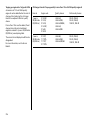
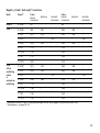
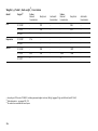
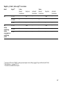
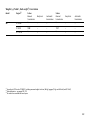
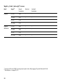
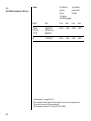
Data specific to your vehicle
Please enter your vehicle’s data here to keep it easily accessible.
This information is available under the section "Technical data" as well as on the identification plate.
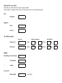
Fuel
Designation
Engine oil
Grade
Viscosity
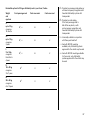
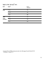
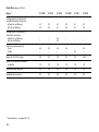
Tyre inflation pressure
Tyre size
with up to 3 persons
Summer tyres
Front
Rear
Front
Rear
Winter tyres
Front
Rear
Front
Rear
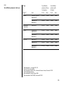
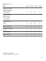
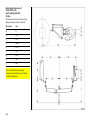
Weights
Permissible gross vehicle weight
–
EC kerbweight
=
Loading
Level control
Bumper Height
0
with full load
see page 92
Your Corsa
Developed to the latest findings of vehicle research, it offers technical sophistication and exceptional comfort.
Your vehicle represents an ideal synthesis of advanced technology, outstanding safety, environmental compatibility and economy in
operation.
It now lies with you to drive your vehicle safely and to see it performs perfectly.
This Owner's Manual provides you with all the necessary information to that end.
The Owner's Manual should always be kept in the vehicle: ready to hand in the glove compartment.
Make use of the Owner's Manual:
z
z
z
z
z
Its “In brief” section will give you an initial overview.
Its index will help you find what you want.
It will familiarize you with the sophisticated technology.
It will increase your pleasure in your vehicle.
It will help you to handle your vehicle expertly.
The Owner's Manual is designed to be clearly laid-out and easily understood.
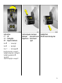
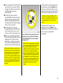
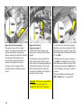
This symbol:
6 signifies: continue reading on next page.
3 The asterisk signifies equipment options not in all vehicles (model variants, engine options, models specific to one country, optional
equipment, Genuine Vauxhall Parts and Accessories).
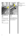
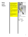
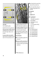
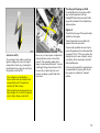
Text highlighted in yellow in particular indicates possible risk of accident and
injury. Disregard of these notes can lead to injuries which may be fatal. Vehicle
passengers must be informed accordingly.
Yellow arrows in the illustrations serve as points of reference or indicate some action to be performed.
Black arrows in the illustrations indicate a reaction or a second action to be performed.
We wish you many hours of pleasurable driving
Your Vauxhall team
1
2
Contents
Commitment to customer
satisfaction:
Our aim: to keep you happy with your
vehicle. All Vauxhall Authorised Repairers
offer first class service at competitive
prices. Experienced, factory-trained
technicians work according to factory
instructions.Your Authorised Repairer can
supply you with GENUINE VAUXHALLAPPROVED PARTS, which have undergone
stringent quality and precision checks, and
of course useful and attractive
VAUXHALL-APPROVED ACCESSORIES.
Our name is your guarantee!
For details of the
Vauxhall Authorised Repairer Network
please ring this number; 01582 - 427200
In brief ....................................................... 4
Instruments ............................................. 29
Keys, doors, bonnet ............................... 44
Seats, Interior .......................................... 56
Safety systems ........................................ 70
Lighting ................................................... 91
Windows, sun roof, folding top ............. 95
Climate control ..................................... 104
Easytronic ............................................ 116
Automatic transmission ...................... 122
Driving hints ......................................... 128
Saving fuel,
protecting the environment ............. 130
Fuel consumption, fuel, refuelling ...... 132
Catalytic converter, exhaust gases .... 134
Drive control systems .......................... 138
Brakes .................................................... 142
Wheels, tyres ......................................... 146
Roof racks,
caravan and trailer towing ............. 150
Self-help ................................................ 158
If you have a problem .......................... 194
Maintenance, Inspection system ....... 196
Vehicle care .......................................... 207
Technical data .................................... 212
Index ...................................................... 244
3
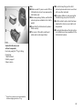
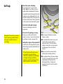
In brief
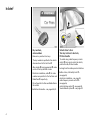
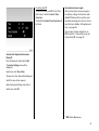
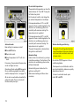
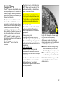
Key numbers,
code numbers
Remove key number from keys.
The key number is specified in the vehicle
documents and in the Car Pass 3.
Alloy wheels 3, towing equipment 3: make
a note of the key identifier codes.
Electronic immobiliser, radio 3: the code
numbers are specified in the Car Pass and
Radio Pass 3 respectively.
Do not keep the Car Pass and Radio Pass in
the vehicle.
6 Further information – see pages 44, 45.
4
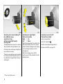
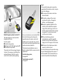
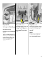
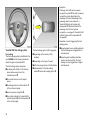
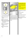
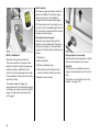
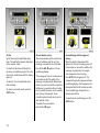
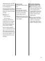
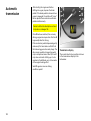
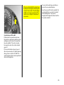
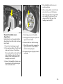
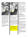
Unlock driver’s door:
Turn key in driver’s door lock,
lift door handle
To unlock using radio frequency remote
control 3: Aim remote control at vehicle,
push button q, lift door handle.
Locking from the inside: press lock buttons.
6 Door locks, child safety locks 3 –
see page 44,
electronic immobiliser – see page 45,
radio frequency remote control 3 –
see page 46,
central locking system 3 – see page 48,
Vauxhall alarm system 3 – see page 53.
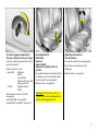
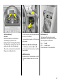
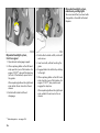
To unlock luggage compartment:
Turn key clockwise as far as it will go
In order to avoid being locked out, the key
cannot be removed.
Position of key slot in lock:
– Horizontal
Tailgate is
locked
and unlocked
together with the central
locking system 3.
– Vertical
Tailgate is always
locked.
radio frequency remote control 3 –
see page 46,
central locking 3 – see page 48,
Vauxhall alarm system 3 – see page 53.
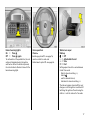
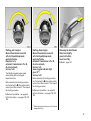
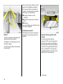
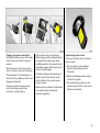
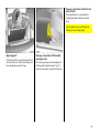
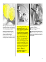
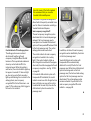
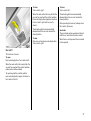
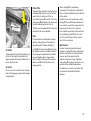
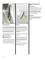
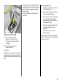
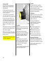
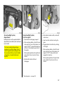
Seat adjustment 3:
Pull handle,
slide seat,
release handle,
allow seat to audibly latch into
position
Never adjust the driver’s seat whilst driving.
It could move in an uncontrolled manner
when the handle has been pulled.
Adjusting seat backrest:
Turn handwheel
Move seat backrest to suit seating position.
Do not lean on seat backrest whilst
adjusting it.
6 Seat position – see page 56.
6 Seat position – see page 56.
Important: Do not sit nearer than 10
inches (25cm) from the steering wheel, to
permit safe airbag deployment.
5
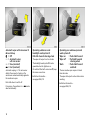
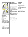
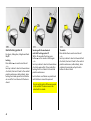
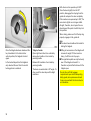
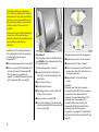
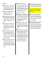
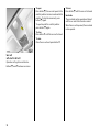
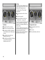
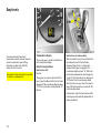
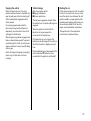
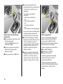
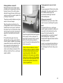
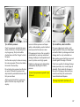
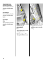
Adjusting seat height 3:
Pull lever at side
Folding down the seat backrests 3:
Raise release lever
Lift lever and remove weight from seat to
raise it or press down on seat with body
weight to lower it.
To enter and leave the rear seat area, tilt
front seat backrest forwards.
Never adjust the driver’s seat whilst driving.
It could move in an uncontrolled manner
when the lever has been pulled.
6 Seat position – see page 56.
6
6 Seat position – see page 56.
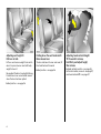
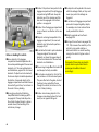
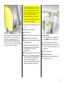
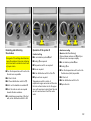
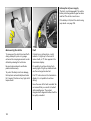
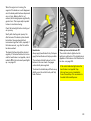
Adjusting head restraint height:
Tilt forwards to release,
hold firmly and adjust height,
then release
6 Head restraint position – see page 56,
further information, removal – see page 57,
rear head restraints 3 – see page 57.
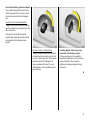
Adjusting interior mirror:
Swivel mirror housing
Swivel lever on underside of mirror housing
to reduce dazzle at night.
Adjusting automatic anti-dazzle
interior mirror 3:
Swivel mirror housing
Dazzle at night is automatically reduced.
The mirror does not reduce dazzle when:
z The ignition is switched off,
z reverse gear is engaged or selector lever
set to R,
z interior lighting has been switched on.
7
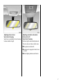
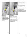
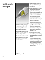
Adjusting exterior mirror:
Swivel handle in any direction from
inside
6 Further information,
aspherical exterior mirror 3 – see page 90.
Electrically adjustable exterior
mirrors 3:
Four-way switch in driver’s door
Toggle switch to left or right: four-way
switch moves appropriate mirror.
6 Additional information,
aspherical exterior mirror 3 – see page 90,
heated exterior mirror 3 – see page 19.
8
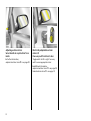
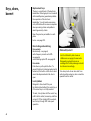
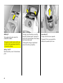
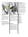
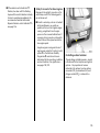
Fitting seat belt:
Draw seat belt smoothly from
inertia reel,
guide over shoulder
and engage in buckle
The belt must not be twisted at any point.
The lap belt must lie snugly against the
body. The backrest must not be tilted back
too far (recommended tilting angle
approx. 25°).
To release belt, press red button on belt
buckle.
6 Seat belts – see pages 71 to 75,
airbag systems 3 – see page 76,
seat position – see page 56.
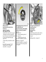
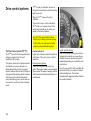
Disengaging steering column lock:
To release the lock,
move the steering wheel slightly
and turn the key to position I
Positions:
o = Ignition off
I = Steering released, ignition off
II = Ignition on,
with diesel engine: Pre-heat
III = Start (transmission in neutral)
Steering wheel adjustment 3:
Swivel lever down,
adjust height,
swivel lever up,
engage
Adjust steering wheel only when vehicle is
stationary and steering column lock is
released.
6 Airbag systems – see page 76.
6 Starting – see page 23,
electronic immobiliser – see page 45,
remove key and lock steering wheel –
see page 24.
9
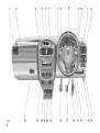
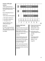
10
1
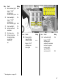
Page
Side air vents ................................. 107
2
Front passenger airbag 3 .............. 76
3
Radio 3,
Infotainment system 3 ................... 42
4
Hazard warning lights .................... 17
LED for
Vauxhall alarm system 3 ................ 53
5
Display 3 of time, date,
outside temperature,
radio 3,
Infotainment system 3 ................... 37
6
Centre air vents .............................. 107
7
Turn signals, headlight flash,
dipped and main beam ................. 15
Cruise control 3 .............................. 140
8
Horn .................................................. 17
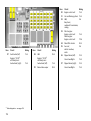
Page
Instruments ...................................... 29
Page
19 Heated seats 3 ............................. 107
10 Stalk for windscreen wiper
and wash system,
headlight wash system 3 and
rear window wash system 3 ........... 17
20 Accessory socket or
cigarette lighter .............................. 67
9
11 Light switch ................................ 15, 91
12 Headlight range adjustment 3 ...... 92
Fog tail light ..................................... 93
Front fog lights 3 ............................. 93
Instrument illumination ................... 93
13 Bonnet release lever ........................ 55
14 Ignition switch
with steering wheel lock ................... 9
21 Ashtray 3 ........................................ 68
22 Air conditioning system 3 ............ 106
Heated rear window 3 ............ 19, 106
Air recirculation system 3 ............ 106
23 Heating and ventilation ............... 104
Electronic air conditioning
system 3 ......................................... 111
24 Glove compartment ........................ 69
with telematics unit 3 ..................... 42
15 Steering wheel adjustment 3 ........... 9
16 Accelerator pedal ................. 128, 129
17 Brake pedal ........................... 128, 142
18 Clutch pedal .................................. 129
11
11
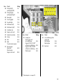
Control indicators
X
q
>
A
Seat belt 3:
see page 29.
Headlight range control 3:
see page 92.
Front fog lights 3:
see pages 29, 93.
Engine electronics,
immobiliser 3,
automatic transmission 3,
Easytronic 3,
fault:
see pages 29, 45, 136.
Z
Exhaust emission 3:
see pages 30, 136.
v
Airbag systems 3,
belt tensioners:
see pages 72, 81.
12
I
Oil pressure:
see page 30.
R
Turn signal lights:
see pages 16, 31.
Brake system,
clutch system:
see page 32.
O
u
P
Main beam:
see pages 15, 31.
Anti-lock Brake System 3:
see page 144.
S
!
Glow plugs 3:
see page 31.
Oil level 3:
see pages 32, 198.
EPS
1
Automatic transmission 3,
sporty driving programme:
see page 124.
Electric power-assisted steering 3:
see page 32.
v
T
Automatic transmission 3,
Easytronic 3,
winter programme:
see pages 118, 124.
Traction Control system 3,
Electronic Stability Programme 3:
see page 138.
g
Trailer turn signal 3:
see page 32.
r
Fog tail light:
see pages 31, 93.
Y
Fuel level:
see pages 32, 36, 158.
p
Alternator:
see page 31.
y
Seat occupancy recognition 3:
see pages 81, 82.
Lighting
Light switch,
stalk positions:
see pages 15, 91.
Heating, ventilation,
air conditioning system 3,
electronic air conditioning system 3
x
Air flow:
see pages 105, 114.
Ü
Heated rear window 3:
see pages 106, 113.
n
Air conditioning system 3:
see page 106.
4
Air recirculation system 3:
see page 106.
7
Lights off
8
Parking lights
9
Dipped and main beam
V
0
Courtesy light:
see page 93.
to windscreen and
front door windows,
J
AUTO Automatic mode 3:
see page 112.
to windscreen, front
door windows
and footwell,
ECO
Operation without cooling 3:
see page 113.
K
L
M
to footwell,
ß
Heated seats 3:
see page 107.
P
O
Main beam:
see page 15.
Turn signal lights:
see page 16.
>
Front fog lights 3:
see page 93.
r
Fog tail light:
see page 93.
k
Instrument illumination:
see page 93.
?
Headlight range adjustment 3:
see page 92.
¨
Hazard warning lights:
see page 17.
Air distribution:
see pages 105, 113,
to head area and footwell,
to head area.
13
Sun roof 3
l
\
Sun roof
opening / lowering:
see page 98.
Sun roof
closing / raising:
see page 98.
Folding top 3
\
Folding top
opening:
see pages 99, 101.
l
Folding top
closing:
see pages 99, 101.
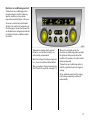
Date, time, radio
Information display 3:
see page 37.
Ö
On button for date
and time
;
Setting buttons for date and time
Remote control for radio and
Infotainment system 3:
see page 26.
Miscellaneous
p
Central locking system 3
locking:
see page 48.
q
Central locking system 3:
unlocking:
see page 48.
)
Cigarette lighter:
see page 67.
j
Horn:
see page 17.
/
Bonnet:
see page 55.
T
Winter programme,
automatic transmission 3,
Easytronic 3:
see pages 118, 124.
+
First Aid kit 3:
see page 162.
¨
Warning triangle 3:
see page 162.
Windscreen wiper
Stalk positions:
see page 17.
§
$
Off
%
&
Slow
14
Interval operation or
automatic wiper with rain sensor 3
Fast
Light switches:
7 = Off
8 = Parking lights
9 = Dipped or main beam
Push 0
=
Courtesy light
Push r
=
Fog tail light
Press >
=
Front fog lights 3
Switch on dipped or main beam:
Main beam
= Move stalk forward
Dipped beam = Move forward
again
Headlight flash:
Pull stalk towards steering wheel
6 Further information – see page 91,
headlight warning device – see page 24,
headlight range adjustment 3 –
see page 92,
daytime running lights – see page 91.
15
Operating door-to-door lighting1) 3:
Key to o and remove,
open driver’s door,
pull turn signal stalk towards
steering wheel
The dipped beam remains on for a further
30 seconds after closing the driver’s door.
If the driver’s door is left open, the lights will
go out after two minutes.
The door-to-door lighting can be cancelled
by inserting the key in the ignition switch or
by pulling the turn signal stalk to steering
wheel again.
1)
"Door-to-door" light function.
16
Operating turn signal lights:
Stalk in rest position
Right = Up
Left
= Down
When the steering wheel is turned back, the
stalk automatically returns to its original
position. This will not happen when making
a minor steering manoeuvre such as
changing lane.
When lane changing, move stalk to
resistance point. When released, the stalk
will spring back.
Operating cruise control 3:
Press buttons on stalk
Switch on: tap button I.
Switch off: tap button §.
Resume at stored speed: tap button R.
6 Cruise control 3 – see page 140.
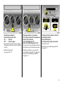
Hazard warning lights:
On = Press ¨
Off = Press ¨ again
To aid location of the pushbutton, the red
surface is illuminated when the ignition
switched on. When the button is pressed,
its control indicator flashes in time with the
hazard warning lights.
Horn operation:
Press j
6 Airbag systems 3 – see page 76,
remote control for radio and
Infotainment system 3 – see page 26.
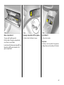
Windscreen wiper:
Stalk up
§ = Off
$ = Adjustable interval
% = Slow
& = Fast
Setting wiper interval to a value between
2 and 15 seconds:
Stalk to interval switching $,
stalk to §,
wait for desired interval,
stalk back to interval switching $.
The interval remains stored until the next
change or until the ignition is switched off.
Switching the ignition off and moving the
stalk to $ sets the interval to 7 seconds.
17
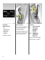
Automatic wiper with rain sensor 3:
Move stalk up
§ = Off
$ = Automatic wiper
with rain sensor
% = Slow (constant)
& = Fast (constant)
Automatic wiping $: The rain sensor
detects the amount of water on the
windscreen and automatically regulates
the windscreen wiper.
Push stalk down to switch off.
If necessary, the positions % or & can be
selected manually.
18
Operating windscreen and
headlight wash systems 3:
Pull stalk towards steering wheel
The wiper will swipe for a few strokes.
The headlight wash system 3 can be
operated when the lights are on.
On vehicles fitted with rain sensor 3, keep
the sensor area clean.
6 Further information –
see pages 204, 210.
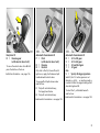
Operating rear window wiper and
wash systems 3:
Wiper on
= Push stalk forward
Wiper off
= Pull stalk towards
steering wheel
Wash
= Push stalk forward
and hold
The rear window wiper swipes in timed
interval mode.
The wiper will swipe for a few strokes when
washing.
6 Further information –
see pages 204, 210.
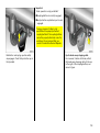
Heated rear window 3,
heated exterior mirrors 3:
On = Press Ü
Off = Press Ü again
Rear window and exterior mirror heating
with ignition switched on. Switch-on telltale
in switch.
6 Further information –
see pages 106, 113.
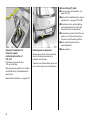
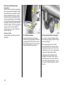
Clearing misted or icy windows:
Turn rotary switches for temperature
and air flow clockwise,
set air distribution to V,
press air conditioning switch n 3
Setting electronic climate control to
automatic mode 3:
Press AUTO button,
set temperature using rotary knob
Close centre air vents; push sliders inwards.
Direct side air vents towards door windows.
6 Electronic air conditioning system 3 –
see page 111.
6 Heating, ventilation – see page 104,
air conditioning system 3 – see page 106,
electronic air conditioning system 3 –
see page 111.
Open all air vents.
19
Info display 3:
Display of information
–
–
–
–
–
Time,
Outside temperature,
Radio 3 and date,
Navigation 3,
Telephone 3.
6 Info display – see page 37.
Manual transmission:
Reverse gear: with vehicle stationary, pull
the ring up three seconds after declutching and engage gear.
If the gear does not engage: with lever in
neutral, release clutch pedal and depress
again, then repeat gear selection.
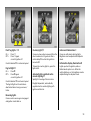
Easytronic 3:
N
= Neutral / Start position
o
= Centre position
(Drive position)
+
= Higher gear
= Lower gear
A/M = Change between
Automatic and
Manual mode
Only start in N with foot brake applied.
6 Further information – see page 116.
20
Easytronic 3:
R = Reverse gear
(with selector lever lock)
To move the selector lever from N to R
press the button on the lever.
6 Further information – see page 116.
Automatic transmission 3:
P = Park
(with selector lever lock)
R = Reverse
N = Neutral
Only start in P or N, to leave P switch
ignition on, apply foot brake and pull
handle beneath selector lever.
To engage P or R pull release under
selector lever.
P:
R:
Only with vehicle stationary,
first apply hand brake
Only with vehicle stationary
6 Automatic transmission – see page 122.
Automatic transmission 3:
D = 1st to 4th gear
3 = 1st to 3rd gear
2 = 1st and 2nd gear
1 = 1st gear
also
S = Sporty driving programme
Select 3, 2 or 1 if certain gears are not
desired, e.g. 4-3-4 . . . on winding roads, or
in order to utilize the engine braking effect
when driving downhill.
To select 3 or 1 pull handle beneath
selector lever.
6 Automatic transmission – see page 122.
21
Before starting off, check:
z For tyre pressure and condition – see
pages 147, 233.
z Engine oil level and fluid levels in engine
compartment – see pages 197 to 204.
z All windows, mirrors, exterior lighting
and number plates are free from dirt,
snow and ice and are operational.
z No objects are placed in front of the rear
window, on the instrument panel or in
the area in which the airbags inflate.
z Seats, seat belts and mirrors are
correctly adjusted.
Automatic transmission 3:
Protection against
unintentional selection of
P, R, 3 or 1
Exhaust gases are poisonous
Pull release under selector lever,
1, P: up to final stop.
Therefore never inhale exhaust gases, and
never run the engine in an enclosed space.
When selecting any position from 1 to N or
from R to D do not pull handle beneath
selector lever.
6 Automatic transmission – see page 122.
22
Exhaust gases contain carbon monoxide,
which is extremely poisonous but is
odourless and colourless.
z Brake operation.
Starting, petrol engine:
Manual transmission in neutral
with clutch pedal depressed,
apply foot brake,
Easytronic in N,
automatic transmission in P or N,
do not accelerate,
turn key to III
The initially increased engine speed
automatically falls as the engine
temperature rises.
Before repeating the starting procedure,
turn the key back to o in the ignition switch,
remove it and then reinsert it. Then repeat
the starting procedure.
6 Electronic immobiliser – see page 45,
further information – see pages 128, 129,
158.
Starting, diesel engine:
Manual transmission in neutral
with clutch pedal depressed,
apply foot brake,
automatic transmission in P or N,
do not accelerate,
turn key to II;
when pre-glow indicator light
goes off1),
turn key to III
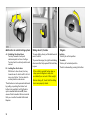
Releasing the hand brake:
Raise lever slightly,
press lock button,
lower lever fully
6 Brakes - page 142
Before repeating the starting procedure,
turn the key back to o in the ignition switch,
remove it and then reinsert it. Then repeat
the starting procedure.
6 Electronic immobiliser – see page 45,
further information – see pages 128, 129,
158.
1)
Preheating system switches on only if outside
temperature is low.
23
Advice when parking:
z Always apply hand brake firmly. On
slopes apply the hand brake as firmly as
possible.
z With manual transmission, engage first
gear or reverse gear. With Easytronic 3,
place selector lever in mid position
before switching off ignition. With
automatic transmission 3, place selector
lever in P.
z Close window, sun roof 3 and folding
top 3.
Parking the vehicle:
Apply handbrake firmly,
engine off,
remove key,
lock steering wheel,
lock doors
To lock, press button p or turn key
anticlockwise in the lock. To activate the
anti-theft locking system 3 and anti-theft
alarm system 3, press button p twice or
turn key anti-clockwise twice.
Warning buzzers
While driving:
z If seat belt is not fastened1),
z if a specified maximum speed is
exceeded1).
When the vehicle is parked and the driver’s
door is opened:
z If the key is inserted,
z if exterior lights are on,
z if the turn signal stalk is engaged.
z On vehicles with Easytronic 3 the control
indicator R flashes for a few seconds
after the ignition is switched off if the
hand brake has not been applied.
z In vehicles with automatic
transmission 3 the key can only be
removed in selector lever position P.
z Turn steering wheel until lock is felt to
engage (anti-theft protection).
z Engine cooling fan may run on after the
engine has been switched off.
6 Further information – see pages 45, 129,
radio frequency remote control 3 –
see page 46,
central locking system 3 – see page 48,
Vauxhall alarm system 3 – see page 53.
1)
24
Country-specific version.
Genuine Vauxhall Parts and
Accessories
We recommend you use "Genuine Vauxhall
Parts and Accessories" and conversion
parts released expressly for your vehicle
type. These parts have undergone special
tests to establish their reliability, safety and
specific suitability for Vauxhall vehicles.
Despite continuous market monitoring, we
cannot assess or guarantee these
attributes for other products, even if they
have been granted approval by the
relevant authorities or in some other form.
Service work,
maintenance
We recommend that you entrust all work to
a Vauxhall Authorised Repairer, who can
provide you with reliable service and
correctly perform all work according to
factory instructions.
6 If you have a problem– see page 194,
service interval display – see page 196.
"Genuine Vauxhall Parts and Accessories"
and conversion parts approved by
Vauxhall can be obtained from a Vauxhall
Authorised Repairer, of course. You will
also be given comprehensive advice about
permitted technical changes and correct
installation will take place.
That was the most important
information on your first drive
in your Corsa / Combo.
The other pages of this
chapter contain a description
of some interesting functions
in your vehicle.
The remaining chapters of
the owner’s manual contain
important information on
operation, safety and
maintenance and a full index.
For your safety
Carry out regularly the checks
recommended in the individual sections
of this Owner’s Manual.
Ensure that your vehicle is serviced as
specified in the Service Booklet. We
recommend that you consult a Vauxhall
Authorised Repairer.
Have faults remedied without delay!
Consult a workshop. We recommend a
Vauxhall Authorised Repairer. If
necessary, interrupt your journey.
6 Maintenance – see pages 196 to 205
25
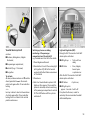
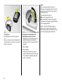
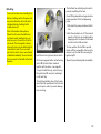
Operating the
Graphical Information Display 3
The functions are called up using the
multifunction button.
The individual menu items are selected by
turning and activated by pushing.
6 Further information – see page 37.
26
Remote control for radio /
Infotainment system
remote control 3
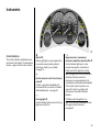
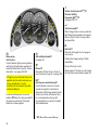
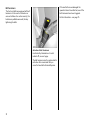
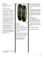
Vauxhall Full-Size airbag system
Radio 3, radio telephone 3 and
Infotainment system 3 functions can be
operated with the buttons on the steering
wheel.
Front airbag system
The front airbag system is triggered in the
event of a serious accident involving a
frontal impact and forms safety cushions
for the driver and front passenger. The
forward movement of the driver and front
passenger is checked and the risk of
injuries to the upper body and head
thereby substantially reduced.
For further information, see the respective
operating instructions.
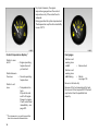
The Vauxhall Full-Size airbag system
comprises several individual systems.
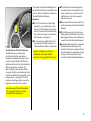
Side airbag system 3
The side airbag system triggers when a
side-on collision occurs and provides a
safety barrier for the driver and/or
passenger in the respective front door
area. This reduces the risk of injury to the
upper body considerably in case of a side
impact.
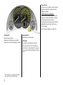
Curtain airbag system 3
The curtain airbag system triggers in case
of a side-on collision and provides a safety
barrier in the head area on the respective
side of the vehicle. This reduces the risk of
injury to the head considerably in case of a
side-on collision.
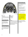
Active head restraints 3
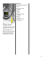
Parking distance sensors 3
In the event of a rear-end impact, the
active head restraints automatically tilt
forward a little. The head is more
effectively supported by the head restraint
and the danger of injuries caused by
hyperextension in the neck area is reduced.
The parking distance sensors
automatically switch on when reversing.
Active head restraints are identified by the
lettering ACTIVE on the head restraint
guide bushes.
If the vehicle approaches an obstacle when
reversing, a series of signals can be heard
in the vehicle interior. The interval between
the signals becomes shorter as the
distance is reduced. If the distance is less
than 30 cm, the signal will be continuous.
6 Further information – see page 141.
6 Further information – see page 76.
27
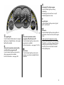
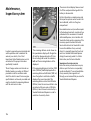
ECOService-Flex
The oil change and service intervals are
flexible, based on a number of different
parameters and the conditions under
which the vehicle is used. Various enginespecific data is continuously recorded and
used to calculate the remaining distance
until the next service is due.
This remaining distance can be shown on
the speedometer display with the ignition
off and the mileage odometer off: Press the
actuating knob under the odometer, InsP
and the remaining distance will be
displayed.
28
With the specially developed engine oil
for vehicles with ECOService-Flex and
average driving conditions, the next engine
oil change is due after a maximum of
2 years or 25,000 miles / 35,000 km (petrol
engine) or after a maximum of 2 years or
30,000 miles / 50,000 km (diesel engine).
When topping up the oil, always use grade
GM-LL-A-025 or GM-LL-B-025 in order to
maintain the flexible maintenance
intervals.
6 Further information –
see pages 196, 215.
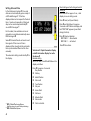
Instruments
Control indicators
The control indicators described here are
not present in all vehicles. The descriptions
however, apply to all instrument versions.
X
Seat belt 3
Warning light lights up (accompanied by
an acoustic warning) when ignition is
switched on: Fasten your seat belt –
see page 74.
?
Fault in Automatic Level Control System
system 3
Contact a workshop immediately. We
recommend that you consult a Vauxhall
Authorised Repairer – see page 92.
>
Front fog lights 3
Control indicator lights up when front fog
lights are switched on.
A
Engine electronics, transmission
electronics, immobiliser, diesel fuel filter 3
Control indicator lights up for a few
seconds when ignition is switched on.
Lights up when the engine is running:
Fault in engine electronics or transmission
electronics. Electronics switch to
emergency running programme. Fuel
consumption may increase and driveability
of the vehicle may be impaired – see
page 136. Contact a workshop. We
recommend a Vauxhall Authorised
Repairer.
If it flashes when the ignition is on:
Fault in the electronic immobiliser system;
the engine cannot be started –
see page 45.
29
Lights up when the engine is running:
Engine lubrication may be interrupted. This
may result in damage to the engine and/or
locking of the drive wheels:
1. Depress clutch.
2. Move gear shift lever to neutral; with
automatic transmission 3 and
Easytronic 3 move selector lever to N.
3. Move out of the flow of traffic as quickly
as possible without impeding other
vehicles.
4. Switch the ignition off (Position I).
Z
Exhaust emission
Control indicator lights up when ignition is
switched on. Goes out shortly after engine
starts.
Lights up when the engine is running:
Fault in emission control system. The
permitted emission limits may be
exceeded. Consult a workshop. We
recommend a Vauxhall Authorised
Repairer.
If it flashes when the engine is running:
For fault that can lead to destruction of the
catalytic converter - see page 136. Consult
a workshop immediately. We recommend
that you consult a Vauxhall Authorised
Repairer.
30
v
When the ignition is off, considerably
more force is needed to brake and steer.
I
Do not remove key until vehicle has
come to a standstill, otherwise the
steering column lock could engage
unexpectedly.
Airbag systems 3,
belt tensioners
see pages 73, 81.
Oil pressure
Control indicator lights up when ignition is
switched on. Goes out shortly after engine
starts. Can light up intermittently when
idling with hot engine; must go out when
engine speed is increased.
Contact a workshop immediately. We
recommend that you consult a Vauxhall
Authorised Repairer.
!
Preheating 3 for diesel engines
Control indicator lights up during
preheating.
Preheating system switches on only if
outside temperature is low.
r
Fog tail lights
Control indicator lights up when fog tail
light is switched on.
p
O
T
Turn signal lights
Control indicator flashes when turn signal
lights are on. Rapid flashes: a turn signal
light bulb has failed.
Automatic transmission winter
programme 3 and Easytronic 3
Control indicator lights up when winter
programme is enabled.
1
Further information – see pages 118, 124.
Further information – see page 124.
Main beam
Control indicator lights up when main
beam is on and when headlight flash is
operated.
Automatic transmission electronically
controlled drive programmes 3
Control indicator lights up when sporty
driving programme is enabled.
P
Alternator
Control indicator lights up when ignition is
switched on. Goes out shortly after engine
starts.
Lights up when the engine is running:
Stop the vehicle and switch off the engine.
The battery is not being charged. Engine
cooling may be interrupted. Contact a
workshop. We recommend a Vauxhall
Authorised Repairer.
31
v
Traction Control system (TCPlus) 3,
Electronic Stability
Programme (ESPPlus) 3
see pages 138, 139.
g
Trailer turn signal 3
When towing a trailer or caravan, indicator
light flashes at same speed as turn signals.
Does not flash if trailer or towing vehicle
turn signal fails.
Y
R
Brake system,
clutch system
Control indicator lights up when ignition is
switched on if hand brake is applied or if
brake/clutch fluid level is too low. Further
information – see pages 143, 202.
If it lights up when the hand brake is not
applied: stop the vehicle; interrupt your
journey immediately. Consult a
workshop. We recommend a Vauxhall
Authorised Repairer.
In vehicles with Easytronic the control
indicator R flashes for a few seconds after
the ignition is switched off if the hand
brake has not been applied.
u
Anti-lock Brake System 3
see page 144.
S
Oil level 3
Illumination: Oil level too low. Check oil
level, if necessary top up oil – see page 198.
EPS1)
Electric power-assisted steering 3
Control indicator comes on for several
seconds when ignition is switched on.
Illumination whilst driving indicates a fault.
Vehicle can continue to be driven. More
force is required when steering. We
recommend that you consult a Vauxhall
Authorised Repairer.
1)
32
EPS = Electric Power-assisted Steering.
Fuel level 3
Illuminate: Fuel supply low, fuel gauge in
reserve area.
Flashing: Fuel supply used up, fill tank
immediately.
Never let the tank run dry!
Diesel engines: If the tank is run dry, bleed
the fuel system as described on page 158.
y
Seat occupancy recognition 3
see pages 76, 81.
Transmission display 3
Indicates selector lever position for
automatic transmission 3, currently
engaged gear for manual transmission, or
mode for Easytronic 3.
Further information – see pages 116, 122.
33
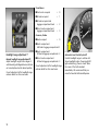
Trip odometer
To return to zero, depress reset knob with
ignition switched on and trip odometer
display activated.
Vehicles with clock in odometer
To set to zero, hold reset knob down for
approx. 2 seconds with ignition switched
on and trip odometer activated.
To switch between trip odometer and clock
display 3 give reset knob a brief press –
see next page.
Service interval display- see page 196.
Tachometer1)
Speedometer1)
Indicates engine speed.
Indicates the vehicle speed.
Warning zone: Maximum permissible
engine speed exceeded; danger to engine.
Odometer
Records the miles (kilometres) driven.
When the ignition is off, the number of
miles driven can be displayed for approx.
15 seconds by briefly pressing the setting
knob.
1)
The instruments in your vehicle may differ
from the instruments illustrated here.
34
Setting the time
With time displayed, press reset knob in
instrument:
Press for approx. 2 seconds,
Hours flash,
Press briefly,
Set hours,
Press for approx. 2 seconds,
Minutes flash,
Press briefly,
Set minutes,
Press for approx. 2 seconds,
Clock is started.
Time display in odometer 3
To switch between trip odometer and time
display 3 give reset knob a short press.
When the vehicle lights are on, the
brightness of the display can be adjusted
using the right-hand adjuster wheel k
below the light switch – see page 93.
35
For physical reasons, the engine
temperature gauge shows the coolant
temperature only if the coolant level is
adequate.
During operation the system is pressurised.
The temperature may therefore rise briefly
to over 100 °C.
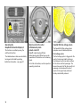
Coolant temperature display1)
Fuel gauge1)
Pointer in zone
at left
Pointer in red
warning zone
or Y lit
Pointer between
the zones
Pointer in red
zone
1)
= Engine operating
temperature not
yet reached
Pointer in red
warning zone
or Y flashing
= Normal operating
temperature
= Refuel –
see page 133.
Never run the tank dry!
= Temperature too
high:
Stop vehicle and
switch off engine.
Danger to engine.
Check coolant level
immediately – see
page 201.
Because of the fuel remaining in the tank,
the amount of fuel required to fill the tank
may be less than the specified tank
capacity.
The instruments in your vehicle may differ
from the instruments illustrated here.
36
= Reserve level.
Information display
Triple information display 3
Display of time, outside temperature, radio
and date.
Multi-information display for radio
telephone 3
Display of time, radio and date, outside
temperature and telephone information
If the ignition is switched on the time and
the outside temperature are displayed,
and the date is displayed if the radio is
switched off.
If the ignition is switched on the time and
the outside temperature are displayed,
and the date is displayed if the radio is
switched off.
When the ignition is off, the time, date and
outside temperature can be made to
appear for approx. 15 seconds by briefly
pressing one of the two buttons adjacent
to the display.
When the ignition is off, the time, date and
outside temperature can be made to
appear for approx. 15 seconds by briefly
pressing one of the two buttons adjacent
to the display.
Graphical Information Display 3
Display of date, time, outside temperature
and Infotainment system.
The information that is displayed depends
on the Infotainment system configuration.
Fault display
--.- °C, F or Safe in the display indicates
a fault. Have the cause remedied. We
recommend that you consult a Vauxhall
Authorised Repairer.
37
Graphical Information Display
system settings 3
Press Infotainment system button BC.
Language selection
You can select the display language for
some functions.
Setting units of measure
You can select which units of measure are
to be used.
The System Settings menu will be
displayed.
In the System Settings menu, select item
Instructions.
In the System Settings menu, select item
Units.
The list of available languages will be
displayed.
Select from the list of units that opens.
Select the required language from the list.
Selections are indicated by a 6 in front of
the menu item.
38
Selections are indicated by a 6 in front of
the menu item.
Adjust contrast
In the System Settings menu, select item
Contrast.
The contrast menu will be displayed.
Confirm the required setting.
Outside temperature
A fall in temperature is indicated
immediately and a rise in temperature
after a time delay.
The symbol T is shown in the display from
3 °C as a warning for icy road surfaces.
In vehicles with Graphical Information
Display 3 a warning message appears in
the display to warn that the road is icy.
Caution: The road surface may already
be icy even though the display indicates
a few degrees above 0 °C.
39
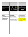
Setting date and time
Deactivating and activating automatic
setting 3
Hold down Ö for approx. 2 sec., clock
display is now in setting mode.
In the Infotainment system 3, time and
date are set automatically upon receipt of
a GPS satellite signal1). If the time
displayed does not correspond to the local
time, it can be set manually in 30-minute
steps or be corrected automatically 3
via an RDS time signal2).
Press Ö twice (until year flashes).
Press Ö and hold down for approx.
3 seconds until } flashes in display and
text "RDS TIME" appears (years flash
during this time).
For the radio, time and date can be set
manually or corrected automatically via an
RDS time signal 3.
Some RDS transmitters do not send correct
time signals. If the incorrect time is
displayed often, deactivate the automatic
time synchronisation 3 and set the time
manually.
The automatic setting is indicated by Ö in
the display.
Press ;, Display indicates:
RDS TIME 0 = Deactivated
RDS TIME 1 = Activated
Press Ö three times.
Vehicles with Triple Information Display
or Multi-Information Display for radio
telephone 3
Manual setting
Switch off radio. Press Ö and ; above the
display as follows:
Press Ö for approx. 2 seconds:
Day flashes
;: Set day
Ö: Month flashes
;: Set month
Ö: Year flashes
;: Set year
Ö: Hours flash
;: Set hours
Ö: Minutes flash
;: Set minutes
1)
2)
GPS = Global Positioning System,
Satellite system for world-wide positioning.
RDS = Radio Data System.
40
Ö: Clock is started.
Correcting time 3
To correct the time, use RDS in the Time /
Date menu to select item Auto. Time
Correction.
Interruption of power supply
After an interruption of power supply or
low battery voltage, the electronic radio
disabler 3, date and time must be reset.
The field behind Auto. Time Correction will
be ticked.
See radio operating instructions for how to
reset electronic disabler. Setting date and
time – see page 40.
Upon receipt of a time signal from an
RDS transmitter1), date and time are set
automatically 3 – see page 40.
Vehicles with Graphical Information
Display 3
Press Infotainment System button BC.
The System Settings menu will be
displayed.
Select menu item Time / Date.
The menu for time / date will be displayed.
Select the menu items required.
Make the desired settings and confirm.
Select menu item OK.
1)
RDS = Radio Data System.
41
As the vehicle aerial is relatively near the
ground, the broadcasting companies
cannot guarantee the same quality of
reception as is obtained with a domestic
radio using an overhead aerial.
z Changes in distance from the
transmitter,
z multi-path reception due to reflection
and
z shadowing
may cause hissing, noise, distortion or loss
of reception altogether.
Infotainment system 3
Radio 3
The radio is operated as described in the
operating instructions supplied.
The display for the radio appears on the
information display.
Car radio reception differs from domestic
radio reception:
The Infotainment system is operated as
described in the operating instructions
supplied.
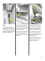
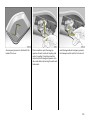
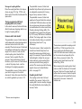
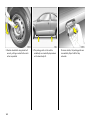
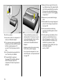
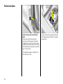
Electronic data acquisition in toll
systems
On vehicles with heat-reflecting
windscreens1) 3, mount the chipcard for
electronic data acquisition and billing in
the black shaded zone of the windscreen
on the left or the right behind the interior
mirror, see illustration. If the chipcard is
mounted outside this zone, there may be
malfunctions in data acquisition.
1)
42
Solar Reflect.
Mobile telephones and radio
equipment (CB) 3
The Vauxhall installation instructions and
the operating guidelines provided by the
telephone manufacturer must be observed
when fitting and operating a mobile
telephone. Failure to do so could invalidate
the vehicle’s operating permit (EU Directive
95/54/EG).
Prerequisites for fault-free operation:
z Professionally installed exterior aerial to
obtain the maximum range possible,
z Maximum transmission power 10 Watt,
z Installation of the telephone in a suitable
spot (see note on page 84).
Obtain advice on predetermined
installation locations for the external
antenna and equipment holder and ways
of using devices with transmission power of
more than 10 Watts. We recommend that
you consult a Vauxhall Authorised
Repairer, who will have brackets and
various installation kits available as
accessories and will install them in
accordance with regulations.
Be sure to use the handsfree attachment if
using the telephone whilst driving. Even this
can be a distraction while driving. Please
observe country-specific regulations.
When used in the vehicle interior, mobile
telephones and radio equipment (CB)
with integrated aerial may cause
malfunctions in the vehicle electronics.
Mobile telephones and radio equipment
(CB) should only be used with an aerial
fitted on the vehicle exterior.
43
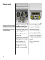
Keys, doors,
bonnet
Replacement keys
The key is a constituent of the electronic
immobiliser. Ordering keys from a Vauxhall
Authorised Repairer guarantees problemfree operation of the electronic
immobiliser. You will avoid unnecessary
costs, difficulties with insurance companies
when processing claims and problems
asserting warranty claims.
Keep the spare key accessible in a safe
place.
Locks – see page 210.
Door locking and unlocking
From outside
Mechanically – see page 4,
radio frequency remote control 3 –
see page 46,
central locking system 3 – see page 48.
From inside
Push down or pull up lock button. To
prevent the driver from being inadvertently
locked out, the button on the driver’s door
cannot be depressed when the door is
open.
Lock cylinders
Designed to free-wheel if they are
forcefully rotated without the correct key or
if the correct key is not fully inserted.
To reset, turn cylinder with the correct key
until its slot is vertical, remove key and then
re-insert it. If the cylinder still free-wheels,
turn the key through 180° and repeat
operation.
44
Child safety locks 3
Use the child safety lock whenever
children are occupying the rear seats.
Disregard may lead to injuries or
endanger life. Vehicle passengers should
be informed accordingly.
Turn rotary knob at rear door lock from
vertical position using key: door cannot be
opened from the inside.
Electronic immobiliser
The system checks whether the vehicle may
be started using the key that has been
inserted. If the key is recognised as
"authorised" the vehicle can be started.
The check is carried out via a transponder
housed in the key – see page 47.
To activate:
Switch off engine, turn key to position o
and remove.
To deactivate:
Turn key to position II (ignition on); the
engine can then be started.
Deactivation is not possible in any other
way, so keep spare key accessible in a safe
place!
Control indicator for immobiliser A
When the ignition is switched on, the
control indicator A lights up briefly. If the
control indicator flashes when the ignition
is on, there is a fault in the immobiliser
system. The engine cannot be started:
1. Turn key to o in ignition switch and
remove.
2. Reinsert key in ignition switch.
3. Then repeat starting procedure.
If the control indicator A continues to
flash, try to start the engine using the spare
key and consult a workshop. We
recommend a Vauxhall Authorised
Repairer.
If the control indicator A lights up after
the engine has started, there is a fault in
the engine electronics or the automatic
transmission – see pages 126, 136.
Note
The immobiliser does not lock the doors.
Therefore, always lock vehicle before
leaving unattended and enable anti-theft
alarm system 3 – see page 53.
The Car Pass contains all of the vehicle’s
data and should therefore not be kept in
the vehicle.
Have your Car Pass on hand when
consulting a Vauxhall Authorised Repairer.
45
Fault
If the central locking system cannot be
operated with the remote control, it may be
due to the following:
z The range of the remote control has
been exceeded.
z The battery voltage of the remote
control unit is too low. Change the
battery – see following page.
Radio frequency remote control 3
The radio frequency remote control is
integrated in the key.
For your convenience, we recommend that
the central locking system always be
operated using the remote control unit.
Used to operate:
z Central locking system,
z Mechanical anti-theft locking system 3,
z Vauxhall alarm system 3.
Handle remote control with care, protect
from moisture and high temperatures and
avoid unnecessary operation.
The remote control has a range of approx.
3 metres. The range can be affected by
external influences. Point the remote
control at the vehicle when operating.
The hazard warning flashers come on
briefly to indicate that the remote control is
operational.
Central locking system,
see page 48.
Vauxhall alarm system 3,
see page 53.
46
z Frequent, repeated operation of the
remote control outside the reception
range of the vehicle (e.g. too far from
vehicle, remote control is then no longer
recognised). To synchronise remote
control, see next column.
z If the central locking system is
overloaded as a result of repeated
operation at short intervals, the power
supply is cut off for approx. 30 seconds.
z Interference from higher-power radio
waves from other sources.
For central locking system operation using
key, see following pages. Have cause of
fault remedied. We recommend that you
consult a Vauxhall Authorised Repairer.
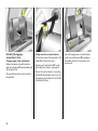
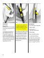
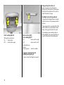
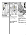
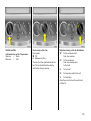
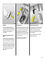
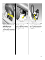
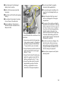
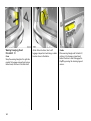
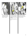
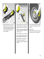
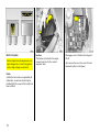
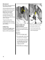
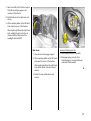
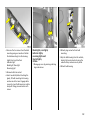
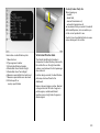
Changing the remote control battery
Exchange the battery as soon as the range
of the remote control starts to become
reduced.
Detach remote control from key section
with a screwdriver, as shown in the figure.
The transponder for the immobiliser is in
the front of the key. Make sure that it is not
damaged or detached.
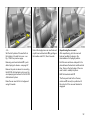
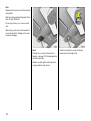
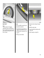
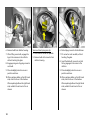
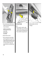
Position screwdriver and open remote
control by making a gentle rotary
movement – see figure above.
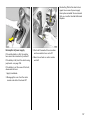
Open up the remote control. Remove
battery using screwdriver. Replace batterysee page 237 for battery type, noting
installation position. Close remote control
and audibly engage. Slide remote control
into key fob and engage.
The battery change must be performed
within 3 minutes, otherwise the remote
control will have to be resynchronized –
see next column.
Make sure that you dispose of old batteries
in accordance with environmental
protection regulations.
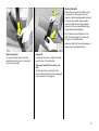
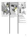
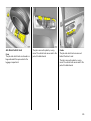
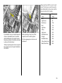
Synchronizing remote control
In the event of malfunctions, synchronize
remote control:
1. Switch on ignition; system will then
remain in synchronizing mode for
30 seconds.
2. Briefly press button p or q on remote
control unit in ignition.
3. The central locking system locks and
unlocks to show that the remote control
has been synchronized.
47
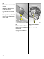
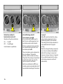
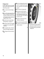
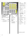
Central locking system 3
For doors, sliding door, tailgate and tank
flap 3.
Locking
Press button p on remote control unit
– or –
turn key in driver’s door lock towards rear
of vehicle, then turn it back to the vertical
position and remove; alternatively, when
locking from inside, press the lock button
on one of the front doors with the doors
closed.
48
Securing with the mechanical
anti-theft locking system 3
Within 10 seconds of locking, press
button p on the remote control again
– or –
turn key in driver’s door lock towards rear
of vehicle again within 10 seconds after
locking, then turn it back to the vertical
position and remove.
Lock buttons on all doors are positioned
such that doors cannot be opened.
Do not use the system if there are people
in the vehicle! The doors cannot be
unlocked from inside.
To unlock
Press button q on remote control unit
– or –
turn key in driver’s door lock towards front
of vehicle, then turn it back to the vertical
position and remove; alternatively, when
unlocking from inside, pull up the lock
button on driver’s door.
Note
z To prevent the driver from being
inadvertently locked out, the button on
the driver’s door cannot be depressed
when the door is open.
z If the driver’s door is not closed properly,
the central locking system will unlock
again immediately after locking.
z 30 seconds after unlocking using the
radio frequency remote control the doors
lock again automatically if no door is
opened.
z To lock the doors from inside (e.g. to
prevent unwanted entry from outside),
push down lock button on driver’s door.
z Locked doors unlock automatically if an
accident of a certain severity occurs (to
permit outside assistance). Prerequisite:
Ignition must not be switched off.
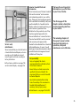
Closing windows and sun roof 3
On vehicles with electric windows 3 and
electric sun roof 3, the windows and sun
roof can be closed from the outside: hold
key in door locking position in driver’s door
lock until all windows and the sun roof are
fully closed.
Care must be taken when operating
the electric windows 3 and electric sun
roof 3. There is a risk of injury,
particularly for children, and a danger
that articles could become trapped.
Overload
If the central locking system is overloaded
as a result of repeated operation at short
intervals, the power supply is cut off for
approx. 30 seconds.
The system is protected by a fuse in the
fusebox – see page 174.
For further information on windows and
the sun roof – see pages 96, 98.
Vehicle passengers should be informed
accordingly.
Keep a close watch on the windows and
sun roof when closing them. Ensure that
nothing becomes trapped in them as
they move.
z In the Combo the central locking will
unlock again immediately after locking if
the sliding door is open. The doors lock
again automatically when the sliding
door is closed.
49
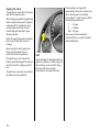
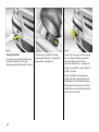
Malfunction in central locking system
Sliding doors 3, Combo
Tailgate
A = Unlocking the driver’s door
Turn key forward in lock past
resistance point as far as it will go.
Turn key back to vertical position and
remove.
To open sliding doors, pull handle towards
rear of vehicle.
Locking
Turn key to vertical position.
To prevent damage, the right-hand sliding
door cannot be fully opened if the tank flap
is open.
To unlock
Turn key to horizontal position.
B = Locking the driver’s door
With driver’s door closed, turn key
towards rear of vehicle until it will not
move any further. Turn key back to
vertical position and remove.
The other doors can be opened and closed
by pulling or pushing the interior lock
button (not possible if anti-theft alarm
system enabled beforehand 3). Have
cause of fault remedied. We recommend
that you consult a Vauxhall Authorised
Repairer.
50
If the vehicle is parked facing down a
slope, open sliding doors may shut
accidentally on account of their weight.
Before driving off, check that the sliding
doors are properly closed.
The lock is released by pressing the button.
Use of central locking system for tailgate
The central locking system and the antitheft locking system for the doors cannot
be locked or unlocked from the tailgate
lock.
Key slot in lock in horizontal position
Tailgate is locked and unlocked using the
remote control or by turning the key in the
driver’s door lock.
If the key is turned to the horizontal
position after unlocking using the central
locking system, the tailgate remains
locked.
Key slot in lock in vertical position
Tailgate remains locked even if vehicle is
unlocked using the remote control or the
key in the driver’s door lock. This position
must be selected if the tailgate is to
remain permanently locked. Turn key
anticlockwise as far as possible beyond
the resistance.
Unlocking tailgate if doors have been
locked with central locking system
Turn key clockwise as far as possible
beyond the resistance from the vertical or
horizontal position. Key cannot be
withdrawn to safeguard against being
locked out.
6
51
Both doors can be opened up to 180°:
Close the door slightly from the 90°
position, disengage the stop lug from the
guide rail and open the door completely.
If the rear doors are opened up to 180°, the
rear exterior lights are no longer visible.
At night, therefore, do not open the rear
doors beyond the point at which they lock
into position.
When closing, make sure that the stop lug
properly engages in the guide rail.
Note
z The saloon has a handle on the inside for
locking the tailgate.
Once the tailgate has been closed and the
key turned back to the horizontal or
vertical position, the tailgate is locked
again.
Tailgate, Combo
Open right-hand door from outside by
raising door handle or from inside by
pressing handle.
In the horizontal position the tailgate is
only unlocked the next time the central
locking system is unlocked.
Release left-hand door from inside by
pressing handle.
52
The doors are arrested at a 90° angle. To
close, push the doors beyond the slight
resistance.
z Fitting of accessories on the tailgate will
increase its weight. If it becomes too
heavy, it will then not stay open.
z The registration plate can only be clearly
seen if the tailgate is closed. It is
therefore not permitted to drive with the
tailgate open.
Do not drive with the luggage
compartment open when transporting
bulky goods, since poisonous exhaust
fumes can penetrate the interior due to
air turbulence.
Vauxhall alarm system 3
monitors
z the doors, sliding doors, tailgate
the bonnet,
z the passenger compartment,
z vehicle tilt, e.g. if it is raised,
z the ignition.
To activate:
All doors, windows and sun roof 3 must be
closed; press button p on the remote
control unit again within 10 seconds after
locking
– or –
turn key in driver’s door lock towards rear
of vehicle again within 10 seconds after
locking, then turn it back to the vertical
position and remove.
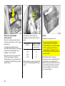
Switching system on excluding
monitoring of the passenger
compartment and the vehicle tilt
e.g. if animals are to be left in the vehicle.
1. Close tailgate and bonnet.
2. Press button in front of the courtesy light
(with ignition off); LED in the hazard
warning light button flashes a maximum
of 10 seconds.
3. Close doors.
4. Switch on Vauxhall alarm system. LED
lights up. After approx. 10 seconds the
system is activated, without monitoring
of the passenger compartment or vehicle
tilt. The LED flashes until the system is
switched off.
Light emitting diode (LED)
During the first 10 seconds of anti-theft
alarm system activation:
z LED lights up
=
Test, switch-on
delay,
z LED blinks
=
Door, tailgate,
bonnet open
or system error.
After the first 10 seconds of anti-theft
alarm system activation:
z LED flashes
= System on,
z LED lights up for
approx. 1 second = Switch-off.
If a system fault occurs, consult a
workshop. We recommend a Vauxhall
Authorised Repairer.
53
Alarm
Only a certain number of alarms are
allowed to be triggered while the Vauxhall
alarm system is switched on (this number is
stipulated by law).
The alarm takes the form of
z an acoustic signal (horn) and
z a visual signal (hazard warning lights).
The duration of the alarm signals is limited
due to legal regulations.
Alarm can be cancelled by pressing a
button on the remote control. The antitheft warning system is switched off at the
same time by pressing the button q.
To deactivate
Press button q on remote control unit
– or –
turn key in driver’s door lock towards front
of vehicle, then turn it back to the vertical
position and remove.
Opening and closing tailgate with
Vauxhall alarm system activated
1. Unlocking: turn key clockwise as far as
possible, tailgate is unlocked and
monitoring of interior and vehicle tilt is
disabled.
2. Open tailgate.
3. Close tailgate.
4. Locking: turn key back to previous
position. Monitoring of the interior and
the vehicle tilt is enabled again after
approx. 10 seconds.
54
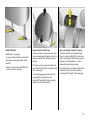
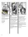
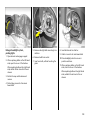
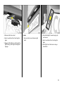
Bonnet
To open the bonnet, pull the release
lever /, located on the driver’s side below
the instrument panel. The bonnet will then
be unlocked and will partially open. Return
release lever to its original position.
To open completely, locate safety catch
approximately a hand’s width to the right
of centre as viewed from the front: lift this
upwards and open bonnet.
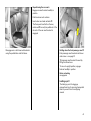
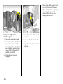
To hold the bonnet in the open position,
insert the support rod located at right
angles above the radiator grille into the
small slot in the underside of the bonnet.
Any dirt or snow on the bonnet can slide
down towards the windscreen when the
bonnet is opened and block the air intake –
see page 115.
Before closing bonnet, press support rod
firmly into its retainer. Lower the bonnet
gradually and then allow it to fall into the
lock under its own weight.
Check that the bonnet is locked in position
by pulling at its front edge. If it is not
engaged, repeat the procedure.
55
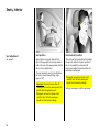
Seats, Interior
Seat adjustment
see page 5.
Seat position
Head restraint position
Adjust driver’s seat such that with the
driver sitting upright the steering wheel is
held in the area of its upper spokes with the
driver’s arms slightly bent.
The centre of the head restraint should be
at eye level. Adjust to highest position if
this is not possible for extremely tall
people, and adjust to lowest position for
extremely small people.
The seat backrests must not be tilted too
far back (recommended tilting angle
approx. 25°).
Important: Do not sit nearer than 10
inches (25cm) from the steering wheel, to
permit safe airbag deployment.
Disregard can lead to injuries which
could be fatal. Vehicle passengers
should be informed accordingly.
56
Disregard can lead to injuries which
could be fatal. Vehicle passengers
should be informed accordingly.
Setting – see page 6 and the next page.
Head restraints
Adjustment – see page 6.
To remove head restraints, release both
springs by pressing and detach head
restraint.
The rear, centre head restraint 3 in the
Combo cannot be removed.
Rear head restraints 3, Corsa
In order to improve vision when rear seats
are unoccupied, push head restraints as far
down as possible. Push detent springs to
release.
If the rear seats are occupied, adjust the
rear head restraints to the occupants’ body
size – see page 6.
To increase luggage compartment size –
see page 58, removing rear head
restraints 3: push both detent springs to
release, remove head restraint.
Rear, centre head restraint 3, Combo
The head restraint can be pushed right
down to improve visibility if the centre rear
seat is unoccupied or to allow the rear seat
backrests to be folded down. To do so,
release both springs by pressing.
If the centre seat is occupied, set the head
restraint to the first or second position
according to the height of the passenger.
57
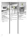
Extending the luggage
compartment, Corsa
Changing angle of rear seat backrest
Release one-piece rear seat backrest or
split rear set backrests 3 using handles and
tilt forward a little.
The rear seat backrests can be locked in
two positions.
58
Folding down the rear seat backrests
Slot the latch plates of the seat belts in the
holders 3 in the side trim cover.
Removing rear head restraints 3 – push
detent springs to release – see page 57.
Remove the push-in sleeves for mounting
the ISO-FIX child restraint system; see the
accompanying instructions for the ISO-FIX
child restraint system.
Unlock the single-piece rear seat backrest
or split rear seat backrests 3 by pulling on
the handles and fold it / them down onto
the rear seat.
– Or –
Slot the latch plates of the seat belts in
the holders in the side trim cover – see
Fig. 11585 S on previous page.
Removing rear head restraints 3 – push
detent springs to release – see page 57.
Remove the push-in sleeves for mounting
the ISO-FIX child restraint system; see the
accompanying instructions for the ISO-FIX
child restraint system.
Raise the rear seat at its front edge and
swing it forwards.
Unlock the single-piece rear seat backrest
or split rear seat backrests 3 by pulling on
the handles and tilt it / them forwards.
Repositioning the rear seats
After repositioning, lock the rear seat
backrest audibly into place in the
intermediate or full upright position.
Fold the rear seat down and push it into
place between the backrest and the vehicle
floor. Press on the front edge of the rear
seat to lock it audibly into place.
Refit the head restraints 3.
The three-point seat belt on the rear,
centre seat 3 can only be pulled out of
the retractor if the rear seat backrest is
engaged.
59
Removing luggage compartment cover
To remove, unhook the retaining straps
from the tailgate.
Remove the cover from the side guides and
place it behind the seat backrests.
Fit in reverse order.
Notes on loading
see page 66.
60
Luggage compartment extension,
Combo
Folding down the rear seat backrests
Remove rear, outer head restraints 3 –
Push detent springs to release - see
page 57. Push rear, centre head restraint 3
down as far as possible – Push detent
springs to release – see page 57.
– Or –
Remove rear, outer head restraints 3 –
Push detent springs to release –
see page 57. Push rear, centre head
restraint 3 down as far as possible – Push
detent springs to release – see page 57.
Hook seat belt buckles on rear seat
backrests.
Remove the push-in sleeves for mounting
the ISO-FIX child restraint system; see the
accompanying instructions for the ISO-FIX
child restraint system.
Remove the push-in sleeves for mounting
the ISO-FIX child restraint system; see the
accompanying instructions for the ISO-FIX
child restraint system.
Unlock one single-piece rear seat backrest
or both using pushbuttons and fold down
onto rear seat.
Pull up one or both rear seat cushions using
straps provided.
Repositioning the rear seats
Engage rear seat backrest audibly in
position.
Push back rear seat cushions.
Insert outer rear head restraints 3.
The three-point seat belt on the rear,
centre seat 3 can only be pulled out of the
retractor if the rear seat backrest is
engaged.
Disengage one or both rear seat backrests
using the pushbuttons and fold down.
Folding down the front passenger seat 3
Push passenger seat head restraint down
and remove – see page 57.
Tilt passenger seat backrest forward by
lifting the release lever.
To move to upright position, engage
backrest audibly in position.
Notes on loading
see page 66.
Lashing eyes 3
The lashing eyes in the luggage
compartment are for securing transported
items to prevent them from slipping
around.
61
Fitting
Push left side of cover into retainers,
followed by right side.
Push button at right end piece of cover,
and cover engages.
Luggage compartment cover 3,
Combo
Removing
Open cover.
To close
Pull cover towards rear of vehicle using
handle and hook into side retainers.
Press button at right side of cover and
engage by pushing right-hand end piece
to the left. Pull right side of cover out of
retainers, followed by left side.
Do not place any heavy or sharp-edged
objects on the cover.
To open
Unhook cover. It reels in automatically.
62
Safety net 3, Combo
The safety net can be fitted behind the rear
seats or, with the rear seat backrest folded
down, behind the front seats.
Passengers must not be carried behind the
safety net.
There are two installation openings in the
roof frame: open cover. Suspend net rod at
one side and engage in position. Pull net
rod apart, suspend at other side and
engage in position. Close cover.
Fitting behind the rear seats
Fold down both rear seat backrests, hook
tensioning straps into lashing eyes in
vehicle floor and tighten them. Reposition
rear seat backrests and lock them into
position.
Fitting behind front seats
Pull up both rear seat cushions. Fold down
rear seat backrests. Hook tensioning straps
into lashing eyes in vehicle floor and
tighten them.
Removing
Swivel tensioning strap length adjusters
upward and unhook straps. Open the
cover. Unhook net rod and close cover.
63
Luggage compartment grille 3,
Combo
A luggage compartment grille is provided
behind the front seats to prevent the
vehicle occupants from being injured by
loose luggage.
Split luggage compartment grille 3
To enlarge the luggage compartment, the
grille can be moved forwards on the front
passenger’s side.
Push head restraint on front passenger’s
seat down as far as it will go – see page 57.
Tilt front passenger’s seat backrest
forward by raising release lever and push
down to lock in position.
64
Engage lever on luggage compartment
grille at top position, as shown in
illustration.
Engaging the lever prevents damage to
the front passenger’s seat.
Position luggage compartment grille
above retainer in front passenger’s seat
backrest.
Lock luggage compartment grille in
retainer. To do so, engage lever at bottom
position, as shown in illustration.
The luggage compartment grille must
always be locked in one of the retainers
when the vehicle is in use, and the lever
must be engaged at its bottom position.
Notes on loading
see page 66.
Lashing eyes 3
Lashing eyes are provided in the luggage
compartment so that loads can be secured
to prevent them from slipping.
Stowage compartment above front
seats, Combo
The compartment is only suitable for
stowing light objects. Maximum load:
15 kg.
Secure objects to prevent them from
falling out and causing injury.
Bag hangers 3
On the back of the rear seat backrest there
are two fixtures on which carrier bags can
be hung. Maximum load: 10 kg.
Stowage compartment 3 beneath
passenger seat
Lift tray by grasping recessed edge and
pull forwards. Maximum load: 1 kg. To
close the tray push it in and lock it in place.
65
z Combo: If objects are transported in the
luggage compartment, the split luggage
compartment grille 3 must always be
locked in one of the retainers and the
lever must be engaged at its bottom
position – see page 64.
z Combo: Close the luggage compartment
cover so there is no reflection in the rear
window.
z If objects are being transported in the
luggage compartment, the rear seat
backrests must be locked in position –
see pages 59, 61.
Notes on loading the vehicle
z Heavy objects in the luggage
compartment should be placed as far
forward as possible against the rear seat
backrests or, if the rear seat backrests
are folded down, against the front seat
backrests. If objects are to be stacked,
the heavier objects should be placed at
the bottom. Unsecured objects in the
luggage compartment would be thrown
forward with great force, for instance in
the event of heavy braking.
z Secure heavy objects with lashing
straps 3 attached to lashing eyes 3 –
see page 64. If heavy loads slip when
the vehicle is braked heavily or driven
around a bend, the handling of the
vehicle may change.
66
z Do not allow the load to protrude above
the upper edge of the rear seat
backrests, or above the upper edge of
the front seat backrests if the rear seat
backrests are folded down.
z The warning triangle 3 and first-aid kit 3
must always be freely accessible.
z Do not place any objects in front of the
rear window or on the instrument panel.
They are reflected in the glass, obstruct
the driver’s view and will be thrown
through the vehicle, for instance in the
event of heavy braking.
z Combo: when stowing objects in the
stowage compartment above the front
seats, secure against falling out.
z No objects must be placed in the area in
which the airbags inflate, as they could
cause injury when the airbags are
triggered.
z Do not drive with luggage compartment
open when transporting bulky objects,
for example, since toxic exhaust fumes
could penetrate the interior.
z Weights, payload and roof load –
see page 224.
z Driving with a roof load – see pages 128,
131, 150, increases the sensitivity of the
vehicle to cross-winds and has a
detrimental effect on vehicle handling
owing to the vehicle’s higher centre of
gravity.
Disregard of these notes can lead to
injuries which may be fatal. Vehicle
passengers should be informed
accordingly.
The maximum power consumption of
electrical accessories must not exceed
120 watts.
Do not connect any current-delivering
accessories, e.g. electrical charging
devices or batteries.
Electrical accessories connected to the
socket must comply with the
electromagnetic compatibility
requirements laid down in DIN VDE 40 839,
otherwise vehicle malfunctions may occur.
Cigarette lighter ) 3
Accessory socket 3
In front centre console:
The accessory socket or cigarette lighter
socket can be used to connect electrical
accessories. The socket is operational
when the ignition is switched on. Use of the
socket discharges the battery if the engine
is not running. Do not damage the socket
by using unsuitable plugs.
Press cigarette lighter with ignition
switched on. Switches off automatically
when element is glowing. Withdraw
cigarette lighter.
67
Ashtray 3
To be used only for ash and not for
combustible rubbish.
Disregard can lead to injuries which may
be fatal. Vehicle passengers should be
informed accordingly.
Ashtray, front 3
Open the ashtray cover to the resistance
point.
68
To empty, open the ashtray cover fully
beyond its resistance point, causing the
insert to lift. Grip both sides of the ashtray
insert and pull upwards.
To enlarge the storage compartment
remove the ashtray completely.
Rear ashtray 3
To open, swivel the cover upwards.
To empty, lift the cover and pull the
ashtray out upwards by its cover.
Glove compartment
Stowage compartment 3 for glasses
Coin holder 3
To open, pull handle upwards.
On driver’s side: fold down to open.
In the centre console.
On the inside of the glove compartment
cover there is a pen holder.
In vehicles with Infotainment system 3, the
telematics unit 3 can be housed in the
glove compartment.
Sun visors
Use the sun visor to protect from glare by
pulling it down and swivelling it to the side.
69
Safety systems
Three-stage restraint system
Comprising
z Three-point seat belts
z Belt tensioners at the front seats
z Airbag systems for driver’s seat,
passenger seat 3 and outboard rear
seats 3.
The three stages are activated in sequence
depending on the seriousness of the
accident:
z The automatic seat belt locking devices
prevent the belt strap from being pulled
out and thus ensure that the vehicle
occupants are retained in their seats.
z The front seat belt buckles are pulled
downwards. As a result, the seat belts
are instantaneously tightened and the
occupants are made aware of the
deceleration of the vehicle at a very early
stage. This reduces the stress placed on
the body.
z The airbag systems are also triggered in
the event of serious accidents and form a
safety cushion for the occupants.
70
The airbag systems 3 serve to
supplement the three-point seat belts
and belt tensioners. The seat belts must
therefore always be worn. Disregard of
these instructions may lead to injuries or
endanger life. Vehicle passengers should
be informed accordingly.
Be sure to read the accompanying
description of the child restraint system!
Seat belts
Always wear your seat belt, and that
means also in urban traffic and when
you are a rear seat passenger. It can
save your life!
Pregnant women must always wear a
seat belt – see page 74.
In the event of an accident, persons not
wearing seat belts endanger their fellow
occupants and themselves.
Warning light X for the seat belt –
see page 29.
Seat belts are designed to be used by
only one person at a time. They are not
suitable for anyone under 12 years of age
or 150 cm.
For children up to 12 years of age we
recommend the Vauxhall child restraint
system – see page 86.
Three-point seat belts
The vehicle is equipped with three-point
seat belts with automatic retractors and
locking devices, allowing freedom of body
movement although the spring tensioned
belts always ensure a snug fit.
The belt has a "vehicle sensitive retractor"
which is designed to lock during heavy
acceleration or deceleration in any
direction.
71
Belt tensioners
If the seat belts are undamaged the
operation thereof is unaffected, even if the
belt tensioners have been triggered.
The front seat belts are equipped with belt
tensioners. In the event of a head-on or
rear-end collision of a certain severity, the
buckles are pulled downwards, thereby
tightening the belts.
Further information – see page 75.
Actuation of belt tensioners
is indicated by illumination of control
indicator v, see next page.
The belt tensioners must be replaced after
activation. We recommend that you
consult a Vauxhall Authorised Repairer.
72
The system’s integrated self-diagnostics
allows faults to be quickly remedied. Have
your Car Pass on hand when consulting a
Vauxhall Authorised Repairer.
Important
z Do not fit accessories not specifically
released for your vehicle type or store
objects in the belt tensioner operating
area (in the area of the belt tensioners)
due to the risk of injury in the event the
belt tensioners are triggered.
z Do not make any modifications to the
components of the belt tensioners, as
this will render the vehicle unroadworthy.
Control indicator v for belt tensioners
The belt tensioners are monitored
electronically and their operational
readiness is indicated on the instrument
panel by control indicator v. When the
ignition is switched on the control indicator
lights up for approx. 4 seconds. If it
does not light up, does not go off after
4 seconds, or lights up while driving, there
is a fault in the belt tensioner system or the
airbag systems - see page 81. The belt
tensioners or airbag systems may not be
triggered in the event of an accident.
Improper handling (e.g. removal or
installation) could cause the belt
tensioners to be triggered. Risk of injury!
z The belt tensioner and airbag system
control electronics can be found in the
centre console area. In order to avoid
malfunctions, do not store magnetic
objects in this area.
z We recommend that you have the front
seats removed by a Vauxhall Authorised
Repairer.
z The belt tensioners only actuate once.
Please replace belt tensioners that have
been triggered. We recommend that you
consult a Vauxhall Authorised Repairer.
z Applicable safety directives must always
be observed when disposing of the
vehicle. For this reason, disposal should
be performed by an authorised recycling
company. We recommend that you
consult a Vauxhall Authorised Repairer.
Have the cause of the fault remedied.
We recommend that you consult a
Vauxhall Authorised Repairer.
73
Using the belts
Fitting seat belts
Pull the belt out of the retractor and guide
it across the body, making certain that it is
not twisted.
Insert latch plate into buckle. Backrest
must not be tilted too far back, since
this would affect the operation of the
seat belts; recommended tilting angle
approx. 25°. The lap belt must be straight
and lying snugly against the body. Tighten
belt at frequent intervals whilst driving by
tugging diagonal part of belt.
74
On pregnant women in particular, the
lap belt must be positioned as low as
possible across the pelvis so as not to put
too much pressure on the abdomen.
Bulky clothing prevents the belt from fitting
properly. The belt must not rest against
hard or fragile objects in the pockets of
your clothing (e.g. ballpoint pens, keys,
spectacles) because these could cause
injury. Do not place any objects (e.g.
handbags, mobile phones) between the
belt and your body.
Height adjustment
of front seat belt upper anchorage points:
1. Pull belt out slightly.
2. Press belt guide or, in
5-door saloon, push button down.
3. Set desired height.
4. Allow to lock audibly into position.
Do not adjust height while driving.
Adjust height setting such that seat belt
runs over and lies against the shoulder.
The belt must not run over the neck or
upper arm – see page 71, Fig. 13216 S.
Testing the belts
Please check all parts of the belt system
occasionally for damage and correct
operation. Have damaged parts replaced.
In case of an accident, please replace
overstretched belts and triggered belt
tensioners. We recommend consulting a
Vauxhall Authorised Repairer.
Do not perform any alterations on the
belts, their anchorages, the automatic
retractors or the belt buckles.
Make sure that belts are not damaged or
trapped by sharp-edged objects.
Removing the belt
To remove the belt, depress the red
pushbutton on the buckle; the belt will
retract automatically.
Lap belt 3
In centre of rear seat: to adjust the length,
press the top of the latch plate.
Three-point seat belt 3 on centre rear
seat
The belt can only be pulled out of the
retractor if the back seat rests are engaged
in their retainers – see page 61.
75
Exception:
Passenger seat with seat occupancy
recognition system 3. The seat occupancy
recognition system deactivates the
passenger front and side airbags if the
passenger seat is unoccupied or a
Vauxhall child restraint system with
transponders 3 has been fitted to the
passenger seat. Seat occupancy
recognition – see page 81. Vauxhall child
restraint system with transponders 3 –
see page 87.
Examples of events triggering the front
airbag system:
Vauxhall Full-Size airbag system
The front airbag system will be triggered:
Front airbag
The front airbag system is identified by the
word AIRBAG on the steering wheel and
above the glove compartment 3.
z depending on the severity of the
accident,
The front airbag system comprises:
z an airbag with inflator in the steering
wheel and a second one in the
instrument panel 3,
z the control electronics with impact
sensor,
z the airbag systems control indicator v
in the instrument panel,
z seat occupancy recognition 3,
z the control indicator for Vauxhall child
restraint systems y with transponders 3
in the courtesy light.
76
z depending on the type of impact,
z within the range shown in the illustration,
z independently of the side airbag
system 3 and curtain airbag system 3.
z Impact against a non-yielding obstacle:
the front airbags are triggered at low
vehicle speed.
z Impact against a yielding obstacle:
(such as another vehicle): the front
airbags are only triggered at a higher
vehicle speed.
When triggered, the front airbags inflate in
milliseconds and form a safety cushion for
driver and front passenger. The forward
movement of the driver and front
passenger is checked and the risk of
injuries to the upper body and head
thereby substantially reduced.
No impairment of view will occur, because
the airbags inflate and deflate so quickly.
The front airbag system provides
optimum protection when the seat,
backrest and head restraint are correctly
adjusted: Adjust the driver’s seat
according to the occupant’s height so
that when the driver is sitting upright, the
steering wheel is held in the area of its
upper spokes with the driver’s arms
slightly bent. The passenger seat should
be as far back as possible, with the
backrest upright (see pages 5, 56, 74).
Do not place the head, body, hands or
feet on the covers of the airbag systems.
The front airbag system will not be
triggered in the event of
z the ignition being switched off,
z minor frontal collisions,
z accidents in which the vehicle overturns,
z collisions involving a side or rear impact
that is to say, if it would not be of benefit to
the occupants.
Do not place any objects in the area in
which the airbags inflate. Important
information – see page 84.
The three-point seat belt must be
correctly fitted – see page 74.
77
Seat belts must therefore always be
worn. The front airbag system serves to
supplement the three-point seat belts. If
you do not wear your seat belt you risk
being seriously injured, or even thrown
from the vehicle, in the event of an
accident.
In the event of an accident the belt helps
to keep you in the correct seating
position, so that the front airbag system
can provide you with effective
protection.
In addition, the front airbag system will
not be triggered for the front passenger
in versions with seat occupancy
recognition 3 if
z the front passenger’s seat is unoccupied,
z there is a properly fitted Vauxhall child
restraint system with transponders 3.
Seat occupancy recognition see –
page 81. Vauxhall child restraint system
with transponders 3 – see page 87.
Side airbag 3
The side airbag system is identified by the
word AIRBAG on the outboard sides of the
front seat backrests.
The side airbag system will be triggered:
The side airbag system comprises:
z within the range shown in the illustration
on the centre door pillar of the driver’s or
front passenger side,
z an airbag with inflator in the back of
the driver’s and front passenger’s seat
respectively,
z the control electronics,
z the side impact sensors,
z the airbag systems control indicator v
in the instrument panel,
z seat occupancy recognition 3,
z the control indicator for Vauxhall child
restraint systems y with transponders 3
in the courtesy light.
78
z depending on severity of the accident,
z depending on the type of impact,
z independently of the front airbag
system.
Exception:
Passenger seat with seat occupancy
recognition system 3. The seat occupancy
recognition system deactivates the
passenger front and side airbags if the
passenger seat is unoccupied or a
Vauxhall child restraint system with
transponders 3 has been fitted to the
passenger seat. Seat occupancy
recognition – see page 81. Vauxhall child
restraint system with transponders 3 – see
page 87.
There must be no objects in the area in
which the airbag inflates or in the area
between the seat backs and the vehicle
body. Do not place the hands or arms on
the covers of the airbag systems.
Important information – see page 84.
The three-point seat belt must always be
correctly fitted – see page 74.
The side airbags will not be triggered in the
event of
z the ignition is switched off,
z frontal collisions,
When triggered, the side airbag inflates in
milliseconds to form a safety cushion for
the driver or front passenger in the
respective door area. This substantially
reduces the risk of injury to the upper body
in the event of a side-on collision.
z accidents in which the vehicle overturns,
z collisions involving a rear impact,
z collisions involving a side impact outside
the passenger cell.
In addition, the side airbag system will
not be triggered for the front passenger
in versions with seat occupancy
recognition 3 if
z the front passenger’s seat is unoccupied,
z there is a properly fitted Vauxhall child
restraint system with transponders 3.
Seat occupancy recognition see –
page 81. Vauxhall child restraint system
with transponders 3 – see page 87.
Curtain airbag 3
The curtain airbag system is identified by
the word AIRBAG on the roof pillar trim.
The curtain airbag system comprises:
z an airbag with inflator in the roof frame
on the driver’s and front passenger’s side
respectively,
z the control electronics,
z the side impact sensors,
z the airbag systems control indicator v
in the instrument panel.
79
There must be no objects in the area in
which the airbag inflates. Do not place
the hands or arms on the covers of the
airbag systems. Important information –
see page 84.
The three-point seat belt must always be
correctly fitted – see page 74.
The curtain airbags will not be triggered in
the event of
z the ignition is switched off,
z frontal collisions,
z accidents in which the vehicle overturns,
The curtain airbag system will be triggered:
z depending on the severity of the
accident,
z depending on the type of impact,
z within the range shown in the illustration
on the centre door pillar of the driver’s or
front passenger side,
z together with the side airbag system,
z irrespective of seat occupancy
recognition,
z independently of the front airbag
system.
80
When triggered, the curtain airbag inflates
in milliseconds to form a safety cushion in
the head area on the side of the vehicle
affected. This substantially reduces the risk
of injury to the head in the event of a sideon collision.
z collisions involving a rear impact,
z collisions involving a side impact outside
the passenger cell.
Have the cause of the fault remedied.
We recommend that you consult a
Vauxhall Authorised Repairer.
The system’s integrated self-diagnostics
allows faults to be quickly remedied. Have
your Car Pass on hand when consulting a
Vauxhall Authorised Repairer.
Control indicator v for airbag systems
The airbag systems are monitored
electronically together with seat
occupancy recognition 3 and the belt
tensioners. Their operational readiness is
shown by control indicator v in the
instrument panel. When the ignition is
switched on, the control indicator lights up
for approx. 4 seconds. If it does not light
up, does not go out after 4 seconds or
lights up while driving, there is a fault in the
airbag systems, seat occupancy
recognition 3 or the belt tensioners – see
page 73. The systems may fail to trigger in
the event of an accident.
Seat occupancy recognition 3
The seat occupancy recognition system
deactivates the front and side passenger
airbags if the front passenger seat is
unoccupied or a Vauxhall child restraint
system with transponders 3 has been fitted
to the front passenger seat. The curtain
airbag system remains activated.
The control indicator for seat occupancy
recognition is located in the courtesy
light. If this control indicator lights up
after the ignition is switched on for approx.
4 seconds, the vehicle is equipped with seat
occupancy recognition – see Fig. 12135 S
on page 82.
If a Vauxhall child restraint system with
transponders 3 is installed, this control
indicator remains on after the ignition has
been switched on as soon as the system
has detected the seat. Only then can the
child restraint system be used on the
passenger seat.
In addition, vehicles with seat occupancy
recognition can be identified by the sticker
on the front passenger seat.
Vauxhall child restraint systems with
transponders 3 are automatically
detected if correctly fitted to the front
passenger seat. When these child restraint
systems are being used on the front
passenger seat, the front and side airbag
systems for the front passenger seat are
deactivated. The curtain airbag system
remains activated. Pay attention to the
seat occupancy recognition 3 control
indicator – see page 82.
6
81
Control indicator y for Vauxhall
child restraint systems with
transponders 3
The presence of a Vauxhall child restraint
system with transponders 3 is indicated
after the ignition has been switched on by
permanent illumination of the control
indicator y in the courtesy light, as soon
as the seat occupancy recognition system
has detected the child restraint system.
Only Vauxhall child restraint systems
with transponders 3 can be fitted on the
front passenger seat; the use of systems
without transponders poses a danger
to life.
Vauxhall child restraint systems with
transponders 3 are identified by a sticker.
82
If the control indicator does not illuminate
whilst driving, the front and side airbag
have not been deactivated on the
passenger side. Risk of fatal injury to the
child – fit child restraint system to rear seat.
Have cause of fault remedied. We
recommend that you consult a Vauxhall
Authorised Repairer.
If a child restraint system is incorrectly
fitted or the transponders are faulty the
control indicator will flash. Check that child
restraint system has been fitted correctly.
Fitting child restraint system with
transponders 3 – see page 87.
If the control indicator does not illuminate
with a correctly installed child restraint
system there is a fault – risk of fatal injury
to the child. Fit child restraint system to
rear seat. Have cause of fault remedied.
We recommend that you consult a
Vauxhall Authorised Repairer.
If no Vauxhall child restraint system with
transponders 3 is installed the control
indicator must neither illuminate nor flash,
since the passenger side airbag systems
would not be triggered. Have the cause of
fault remedied. We recommend that you
consult a Vauxhall Authorised Repairer.
If the Vauxhall child restraint system
with transponders 3 has been fitted
according to the instructions, the control
indicator for Vauxhall restraint systems
with transponders must light up in the
courtesy light when the ignition is
switched on.
If the control indicator does not
illuminate whilst driving, the airbag
systems have not been deactivated on
the passenger side. Risk of fatal injury. In
this case, fit child restraint system to rear
seat. Have cause of fault remedied. We
recommend that you consult a Vauxhall
Authorised Repairer.
83
Important
z Accessories and other objects must not
be affixed or placed in the area in which
the airbags inflate as they could cause
injury if the airbags are triggered.
z Do not place any objects between the
airbag systems and the vehicle
occupants; danger of injury.
z Use the hooks in the roof frame only to
hang up light articles of clothing or coat
hangers. Do not place any objects in the
pockets of the hanging items – risk of
injury.
z The airbag systems and belt tensioner
control electronics can be found in the
centre console area. In order to avoid
malfunctions, do not store magnetic
objects in this area.
z Do not stick anything on the steering
wheel, instrument panel, front seat
backrests or roof frame in the vicinity of
the airbags, or on the front passenger’s
seat cushion, or cover any of those areas
with other materials.
z Use only a dry cloth or interior cleaner to
clean the steering wheel, instrument
panel, front seat backrests, roof frame
and seat cushion of the front passenger
seat. Do not use any aggressive cleaning
agents.
84
z Only protective covers which are
approved for your Corsa / Combo with
side airbag may be fitted on the front
seats. When fitting the protective covers,
make sure that the airbag units on the
outboard sides of the front seat
backrests are not covered.
z Do not perform any alterations on the
components of the airbag system, as this
would render the vehicle unroadworthy.
z The airbag systems are triggered
independently of each other depending
on the severity of the accident and the
type of impact. The side airbag system
and the curtain airbag system are
triggered together.
z We recommend having the steering
wheel, the instrument panel, all panelling
parts, the door seals, the handles and
the front seats removed by a Vauxhall
Authorised Repairer.
z Each airbag can be triggered only once.
Once triggered, an airbag must be
replaced without delay. We recommend
that you consult a Vauxhall Authorised
Repairer.
z The speeds, directions of movement and
deformation properties of the vehicles,
and the properties of the obstacle
concerned, determine the severity of the
accident and triggering of the airbags.
The degree of damage to your vehicle
and the resulting repair costs alone are
not indicative that the criteria for
triggering of the airbags were met.
The systems can be triggered abruptly
and cause injury if they are handled
improperly.
z Applicable safety directives must always
be observed when disposing of the
vehicle. For this reason, disposal should
be performed by an authorised recycling
company. We recommend that you
consult a Vauxhall Authorised Repairer.
z Persons weighing less than 35 kg should
only travel on the rear seats. This does
not apply to children who are travelling
in child restraint systems with
transponders 3.
Vehicles with front passenger airbag can
be identified by the word AIRBAG above
the glove compartment and the warning
sticker on the side of the instrument panel,
visible when the passenger door is open.
z In vehicles with seat occupancy
recognition 3, do not place any heavy
objects on the front passenger’s seat
otherwise the airbag systems for the
front passenger’s seat may be triggered
in the event of an accident.
z In vehicles with seat occupancy
recognition 3, to prevent malfunctions
do not use protective covers or seat
cushions on the front passenger’s seat.
z When using a Vauxhall child restraint
system with transponders 3 on the front
passenger seat, in order to prevent
malfunctions, no objects (e.g. plastic
sheet, stickers or heated mats) may be
placed under the child restraint system.
Child restraint systems as well as other
heavy objects must never be carried on
the lap of passengers; risk of fatal injury.
If carried in this way, child restraint
systems with transponders 3 in vehicles
with seat occupancy recognition 3 could
lead to front passenger airbag systems
not being triggered in the event of an
accident.
Vehicles with side airbag 3: No child
restraint system 3 may be fitted on the
front passenger’s seat; risk of fatal
injury.
A vehicle with side airbags can be
identified by the word AIRBAG on the
outboard sides of the front seat backrests.
Use of child restraint systems 3 on front
passenger seat in vehicles with airbag
systems 3 but without seat occupancy
recognition 3
Seat occupancy recognition 3 –
see page 81.
Vehicles with front passenger airbag 3
without side airbag 3: Child seats facing
the rear of the vehicle must not be
installed on the front passenger seat, risk
of fatal injury. Child seats facing the
direction of travel (child seats for weight
classes I, II and III, following pages) may
be installed on the front passenger seat
if the seat has been pushed back as far
as it will go and the backrest has been
adjusted such that the lap belt fits
snugly.
85
Seat occupancy recognition in a vehicle is
indicated by the control indicator in the
courtesy light. If this control indicator lights
for approx. 4 seconds when the ignition is
switched on, it indicates that the vehicle is
equipped with seat occupancy recognition
– see page 81.
Seat occupancy recognition in a vehicle
is also indicated by a sticker on the
front passenger seat – see page 86,
Fig. 12106 A.
Use of child restraint systems 3 on front
passenger seat in vehicles with airbag
systems 3 and with seat occupancy
recognition 3
Only Vauxhall child restraint systems
with transponders 3 can be fitted on the
front passenger seats. Use of systems
without transponders poses a danger to
life.
86
The seat occupancy recognition system
detects Vauxhall child restraint systems
with transponders 3 and switches off the
front and side airbag systems for the front
passenger’s seat. The curtain airbag
system remains activated. Seat occupancy
recognition – see page 81.
Vauxhall child restraint systems with
transponders 3 can be identified by the
sticker on the child restraint system.
Child restraint systems 3
The Vauxhall child restraint system is
designed specifically for your Vauxhall and
thus provides optimum safety for your child
in the event of impact. If a different child
safety seat is used, follow the
manufacturers’ instructions for fitting and
use.
Selecting the right system
Your child should be transported facing
backwards in the car as long as possible. It
is appropriate to change the system when
the child’s head can no longer be properly
supported at eye height. The child’s
cervical vertebrae are still very weak and in
an accident they suffer less stress in the
semi-prone backwards position than when
sitting upright.
Permissible options for fitting a child safety seat in your Corsa / Combo
Weight
and
age class
Front passenger seat
Outer rear seats
Centre rear seat
0:
up to 10 kg
or approx.
10 months
B1, ++
U+
U
0+:
up to 13 kg
or approx.
2 years
B1, ++
U+
U
I:
9 to 18 kg
or approx.
8 months to
4 years
B1 = Provided: no passenger side airbag or
with seat occupancy recognition and
Vauxhall child safety systems with
transponders
B2 = Provided: no side airbag,
if the front passenger seat is
slid all the way back, or with
seat occupancy recognition and
Vauxhall child safety systems with
transponders
U = Universally suitable in conjunction
with three-point seat belt
+ = Seat with ISO-FIX mounting
available; only child safety systems
approved for the vehicle may be used
B2, ++
U+
U
II:
15 to 25 kg
or approx.
3 to 7 years
B2
U
U
III:
22 to 36 kg
or approx.
6 to 12 years
B2
U
U
++ = Seat with ISO-FIX mounting available
for Corsa only; only child safety
systems approved for the vehicle may
be used
87
Vauxhall safety cradle without
transponder
From birth up to a weight of 10 kg.
Vauxhall safety cradle with transponders
From birth up to a weight of 10 kg.
The transponders are integrated in the
seat cushion.
Vauxhall Top Safe child safety seat
with or without ISO-FIX securing,
with transponders
From birth up to a weight of 18 kg.
The transponders are integrated in the
seat console.
Comprising:
1 Child seat
2 Carrying cradle 3
3 Floor support 3
4 Seat belt 3
5 Safety support
88
Note
z Children under 12 years or under 150 cm
tall should only travel in an appropriate
child safety seat.
z When transporting children, use the child
restraint systems suitable for the child’s
weight.
z Ensure that the child restraint system is
fitted correctly.
z The covers of the safety cradle and
safety seat can be wiped clean.
z Do not stick anything on the child
restraint systems and do not cover them
with any other materials.
z Only allow children to enter and exit at
the side facing away from the traffic.
z A child restraint system which has been
subjected to stress in an accident must
be replaced.
z You should also observe the instructions
on installation and use supplied with the
child restraint system.
Vauxhall child safety seat
without transponder
from body weight of 91) kg to 36 kg.
Comprising:
1 Seat backrest
2 Safety support
3 Seat cushion
1)
Use of the system is not recommended for
children weighing less than 11 kg.
89
Safety accessories 3
The wide range of Vauxhall accessories
allows you to equip your Corsa / Combo as
you desire. In addition to safety
accessories, items for improving comfort
and a complete range of vehicle care
products, there are many articles which will
be of great value to you when needed.
"Genuine Vauxhall Parts and Accessories"
guarantee high quality and accurate fit.
Exterior mirrors
Sport exterior mirror
For the safety of pedestrians, the exterior
mirrors will swing out of their normal
mounting position if they are bumped.
Reposition the mirror by applying slight
pressure 3.
For the safety of pedestrians, the mirrors
are released from their mountings if they
are bumped with sufficient force.
Aspherical exterior mirror 3
increases the field of view. Estimating the
distance away of vehicles following you is
only possible to a limited extent because of
slight distortion.
90
Relocate the disengaged mirror housing in
its mountings and engage by applying
pressure.
Head restraints
Do not attach objects or components that
are not approved for your Corsa / Combo
to the head restraints, since they can
reduce the protection provided by the
head restraints and could be catapulted
uncontrollably through the vehicle in the
event of hard braking or an accident.
A Vauxhall Authorised Repairer will be
happy to advise you, for example with
regard to:
z Vauxhall child restraint systems,
z Tow ropes,
z Tow rods,
z Jump leads,
z Spare bulb kit,
z Spare fuse kit,
z Halogen fog lights,
z Mud flaps,
z Magnetic light,
z Warning triangle,
z First-aid kit,
z First-aid kit (cushion).
Lighting
Vehicles with daytime running lights 3:
With the ignition on and the light switch
on 7, dipped beam without instrument
illumination is on.
Driving abroad – see page 94.
Turn signals, hazard warning lights,
door-to-door lighting 3
see page 16.
Exterior lights
Turn light switch:
7 = Off
8 = Parking lights
9 = Dipped or main beam
Dipped beam, main beam and headlight
flash – see page 15.
In positions 8 and 9, the tail lights and
number plate light are also illuminated.
91
Corsa Saloon
z Front seats occupied
=
0
z All seats occupied
=
1
z All seats occupied and
luggage compartment load
=
2
z Driver’s seat occupied and
luggage compartment load
=
3
=
0
Corsavan, Combo
z Seats occupied
z Seats occupied and
half load in luggage compartment= 1
Headlight range adjustment ?
z Seats occupied and
full load in luggage compartment = 2
Manual headlight range adjustment 3
Adjust headlight range to four stages of
vehicle loading with dipped beam switched
on: turn adjuster wheel to desired position.
Correct adjustment of the headlight range
reduces dazzle for other road users.
Correct adjustment of the headlight range
reduces dazzle for other road users.
92
z Driver’s seat occupied and
full load in luggage compartment = 3
Automatic Level Control System 3
Controls headlight range in vehicles with
Xenon headlight system. If warning light q
lights while driving, there is a fault. Have
the cause of the fault remedied
immediately. We recommend that you
consult a Vauxhall Authorised Repairer.
Front fog lights > 3
On =
Off =
Press >
Press > again
or switch ignition off
Control indicator > in instrument panel.
Fog tail light r
On =
Off =
Press r
Press r again
or switch ignition off
Control indicator r in instrument panel.
The fog tail lights on the vehicle are
deactivated when towing a caravan /
trailer.
Courtesy light 0
Instrument illumination k
Comes on when a door is opened. Once the
door has been shut it goes out after a
certain delay 3 or when the ignition is
turned on 3.
Comes on with exterior driving lights.
Brightness can be adjusted with adjuster
wheel.
To keep the courtesy light on, press the
light switch.
Lights up when the ignition, radio or
Infotainment system is on. When the
vehicle lights are on, the brightness can be
adjusted using the adjuster wheel.
Automatically regulated centre
console lighting 3
Information display illumination 3
Spotlight in housing of interior mirror.
Daylight-dependent, automatically
regulated centre console lighting with
ignition switched on.
Reversing lights
Come on when reverse gear is engaged
and ignition is switched on.
93
Safeguarding the battery 3
Some consumers such as the interior
lighting switch themselves off after approx.
30 minutes if the ignition is off in order to
protect the battery charge.
Headlights when driving abroad
The asymmetrical dipped beam increases
the field of vision on the passenger side of
the lane.
This causes glare for oncoming traffic if the
vehicle is driven in countries where traffic
drives on the opposite side of the road.
Front reading lights 3
With ignition switched on:
Rear courtesy light,
rear reading light 3
On
Off
On
= Move switch to right
Off
= Move switch to left
= Press button
= Press button again
Light switches on
when a
door is opened = Switch in middle
Luggage compartment and
loading area lighting 3
Comes on when the tailgate is opened.
94
To avoid glare, place masking strips on
both headlights. We recommend that you
consult a Vauxhall Authorised Repairer.
Windows,
sun roof,
folding top
Care must be taken when operating
the electric windows 3 and electric sun
roof 3. There is a risk of injury,
particularly for children, and a danger
that articles could become trapped.
Vehicle passengers should be informed
accordingly.
Keep a close watch on the windows and
sun roof when closing them. Ensure that
nothing becomes trapped in them as
they move.
Before leaving the vehicle, remove the
ignition key in order to prevent
unauthorized operation of the windows
and sun roof.
Door windows
The door windows can be operated with
a crank.
Rear vent windows 3
To open
To close
=
=
Push catch
Pull knee lever,
engage
95
Safety function
If the window glass encounters resistance
above the middle of the window during
automatic closing, it is immediately
stopped and the window opened again.
If the windows do not move easily (e.g. on
account of frost), repeatedly tap the switch
for the window in question until the window
has been closed in stages.
Electric windows 3
Operation with ignition switched on.
Two rocker switches in the driver’s door
handle for the driver and front passenger
side door windows. Additional rocker
switch in the front passenger door handle.
Control indicators in the switches show the
operational status.
To operate window in stages, tap
appropriate switch. For automatic opening
or closing, keep switch pressed for slightly
longer; to stop window movement, tap
switch again.
96
Interruption of power supply
Automatic opening and closing of the
windows is not possible after interruption
of the power supply or a drop in battery
voltage. Activate the window electronics as
follows:
1. Close doors.
2. Switch on ignition.
3. Window completely open.
4. Close window and hold down rocker
switch for at least another 5 seconds.
5. Repeat for each window.
Closing windows from outside
Hold key in door locking position in driver’s
door lock until windows have closed.
Overload
If the system is overloaded, the power
supply is automatically cut off for a short
time.
The system is protected by fuses in the
fusebox – see page 174.
To close
Turn crank to right.
To lower
Turn crank to left.
When the crank will not turn any further the
sun roof has reached the comfort position.
Press unlocking button again and continue
to turn crank to right until sun roof is
closed.
The unlocking button is automatically
released when the sun roof reaches the
closed position.
The unlocking button is automatically
released when the sun roof reaches the
closed position.
Sun shade
The sun shade can be opened and closed
with the sun roof either closed or raised.
To raise
Close sun roof and press unlocking button.
Turn crank to right.
After operating the sun roof, always return
the crank to the recess.
When the sun roof is opened, the sun shade
is also opened.
Sun roof 3
Tilt crank out of recess.
To open
Press unlocking button. Turn crank to left.
When the crank will not turn any further the
sun roof has reached the comfort position,
and air noise will be reduced.
To open beyond the comfort position:
press unlocking button again. Continue to
turn crank to the left.
97
To open
Press button l; the sun roof opens to the
comfort position. Air noise is reduced in this
position. To stop the movement, press
button l again.
To open beyond the comfort position:
press button l again.
To close
Press button \ until the sun roof is closed.
To raise
Close the sun roof and press button \.
Sun roof
with electric drive 3
Operation with ignition switched on.
Buttons l and \ between sun visors.
98
To lower
Press button l until the sun roof is closed.
Sun shade
The sun shade can be opened and closed
with the sun roof either closed or raised.
When the sun roof is opened, the sun shade
is also opened.
Closing sun roof from outside
Hold key in driver’s door lock in the door
locking position until the sun roof is closed.
Fault
If the electric drive fails, the system is
protected by a fuse in the fusebox –
see page 174. Until the fault is remedied,
operate the sun roof as follows.
Slide drive cover toward rear. Push in
spring-loaded centre part of drive shaft
using screwdriver and rotate drive shaft
until sun roof is closed.
Electrically operated
folding sun roof 3, saloon
Operation with ignition switched on.
Buttons \ and l between the sun visors.
To open
Press button \ until folding roof is open.
To close
Press button l until folding roof is closed.
6
99
Note
Release switch as soon as roof has reached
end position.
Roof can only be operated at speeds of less
than 75 mph (120 km/h).
Do not open frozen, icy or snow-covered
roof.
When using a roof rack, check freedom of
movement of electric folding roof in order
to prevent damage.
Fault
If a fault occurs, check relevant fuse in
fusebox – see page 174. Manual operation
if electric drive fails:
Release courtesy light lens at side recess
using screwdriver and remove.
100
Position screwdriver in vicinity of clamps,
release and remove light insert.
Unscrew both screws from drive cover and
remove cover in direction of arrow.
Insert emergency key located in glove
compartment into folding roof drive and
turn until roof is closed.
Electrically operated
folding sun roof 3, Combo
Operation with ignition switched on.
Buttons l and \ between sun visors.
To open
Press button \ until folding roof is open.
To close
Press button l until folding roof is closed.
101
Note
Release switch as soon as roof has reached
end position.
Roof can only be operated at speeds of
less than 75 mph (120 km/h).
Do not open frozen, icy or snow-covered
roof.
When using a roof rack, check freedom of
movement of electric folding roof in order
to prevent damage.
Fault
If a fault occurs, check relevant fuse in
fusebox – see page 174. Manual operation
if electric drive fails:
Unclip drive cover at front and pull off
downward.
102
Remove screw from coupling using
screwdriver.
Vehicle tools – see page 165.
An emergency spanner is attached to the
inside of the cover.
Place screwdriver part of emergency
spanner at mark on side of coupling and
extract coupling. If coupling cannot be
extracted, insert emergency spanner into
drive and slacken by turning forwards and
backwards.
Insert hexagon side of emergency spanner
into hexagon socket and turn to close roof.
103
Climate control
Depending on how the vehicle is equipped,
the climate will be controlled by a heating
and ventilation system with optional air
conditioning system 3 or by an electronic
air conditioning system 3.
Heating and ventilation system with
optional air conditioning system 3
Ventilation, heating and cooling 3 are
combined into one unit that is designed to
provide comfort regardless of the season,
weather or outside temperature.
When cooling 3 is activated, the air is
cooled and dried.
The heating unit heats the air as required in
all operating modes depending on the
position of the temperature switch. The air
supply can be adjusted to suit
requirements by means of the fan.
The version without air conditioning
system 3 does not have a cooling
button n or a recirculation button 4.
104
Electronic air conditioning system 3
The electronic air conditioning system
provides maximum comfort under any
weather conditions, at any outside
temperature and at all times of the year.
To ensure a constant and comfortable
climate in the vehicle, the temperature of
the inflowing air, the air-flow rate and the
air distribution are changed automatically
according to climatic conditions outside
the vehicle.
Electronic air conditioning system see page 111.
Heater controls
Left-hand rotary switch: Temperature
Red zone
=
Warm
Blue zone
=
Cold
Centre rotary switch: Fan
Four speeds:
x Off
4 Maximum air flow
The rate of air flow is determined by the
fan. The fan should therefore also be
switched on during a journey.
Right-hand rotary switch: Air distribution
V
To the windscreen and
front door windows
J
To the windscreen,
front door windows and
to foot well
K
To foot well
L
To head area and to foot well
M
To head area
Open the air vents when the switch is set
to L or M.
105
Heated rear window 3,
heated exterior mirrors 3
Operation with ignition switched on:
On =
Off =
Press Ü
Press Ü again
Control indicator in pushbutton.
Air conditioning system 3
Air recirculation system 4
Air recirculation button 4 is used to
switch the air conditioning system to air
recirculation mode (control indicator).
If fumes or unpleasant odours penetrate
from outside: temporarily switch on air
recirculation system 4.
The air recirculation system minimises the
entry of outside air. The humidity
increases, and the windows can mist up.
The quality of the passenger compartment
air deteriorates which may cause the
vehicle occupants to feel drowsy.
Switch the air distribution to V: the air
circulation system is automatically shut off
to provide faster demisting of the windows.
106
Cooling n
Button n is used to activate the cooling
system (cooling compressor) in the air
conditioning system (control indicator).
The cooling system (cooling compressor) is
only operational when the engine is
running.
When the cooling unit (cooling compressor)
is on, the air is cooled and dehumidified.
Switch off the cooling to conserve fuel
whenever cooling or drying is not required.
At low outside temperatures the cooling
unit (cooling compressor) switches off
automatically.
Centre and side (1)
air vents
To close the vents, push the slider towards
the centre of the vehicle.
Pleasant ventilation to the head area
controlled by the position of the
temperature switch. Temperature switch in
the mid position: cooler air flows from the
centre vents than from the side vents.
To increase the air supply, set the fan to a
higher speed.
Heated seats 3
Two buttons ß in the centre console;
operational for the respective front seat
when the ignition is switched on.
Windscreen defroster nozzles (2)
On =
Off =
The air flow can be directed as desired by
tilting and swivelling the slats.
Air distribution switch set to V or J:
Air is directed onto the windscreen and the
door windows.
Press ß
Press ß again
Control indicators in the pushbuttons.
Additional vents
Located in front of the windscreen, in front
of the door windows and in the front foot
wells.
107
Heating
The amount of heat is dependent on the
coolant temperature and is thus not fully
attained until the engine is warm.
For rapid warming of the passenger
compartment:
z Set the temperature switch in the red
zone.
z Set the fan to speed 3.
z Set the air distribution switch to the
desired position – see page 105.
Ventilation
z Temperature switch: as required,
z Switch fan on, fan setting as desired,
z For maximum ventilation in head area:
Set air distribution switch to M and open
all vents,
z For ventilation to foot well: Set air
distribution switch to K,
z For simultaneous ventilation to the head
area and the foot well: Set air
distribution switch to L.
108
The comfort and general well-being of the
vehicle occupants are to a large extent
dependent on a suitable ventilation and
heating setting.
To obtain a stratification of temperature in
the vehicle with the pleasant effect of "cool
head and warm feet", set the air
distribution switch to K, J or L and the
temperature switch as required.
Heating the foot well
z Set the temperature switch in the
red zone.
z Switch on fan.
z Set the air distribution switch to K.
Demisting and defrosting
the windows
Disregard of the settings described can
cause the windows to become misted up
which can lead to accidents due to lack
of proper vision.
Operation of the system 3
Comfort setting
z Air recirculation system 4 off.
z Cooling n as required.
z Temperature switch: as required.
z Fan: as required.
Maximum cooling
(Maximum Air Conditioning)
Open windows and sun roof 3 briefly so
that warm air can escape rapidly.
z Air circulation system 4 on.
z Cooling n on.
z Set air distribution switch to M or L.
z Turn the temperature switch as far into
the blue zone (cold) as possible.
z Set fan to 3 or 4.
z Open vents as required.
z Set fan to 4.
z Set the air distribution switch to V.
Temperature switch in centre of
adjustment range: warmer air will flow into
the foot well and cooler air into the upper
zone, with warmer air coming from the side
air vents and cooler air from the centre
vents.
z Set air distribution switch to M.
z Turn the temperature switch as far into
the red zone as possible.
z Switch on the heated rear window 3.
z Direct the side air vents as required
towards the door windows.
z For simultaneous warming of the foot
well, set air distribution switch to J.
z Open all vents.
109
Note
see page 115.
Maintenance
see page 115.
Window demisting
Window misting e.g. during damp weather
or with damp clothing:
z Cooling n on.
z Temperature switch: as required.
z Fan: as required.
z Air distribution switch to V, air
recirculation system 4 automatically
switches off.
– or –
If there is still moisture in the system after
previous air conditioning operation, the
windows may mist up. To prevent this, set
air distribution to K before starting engine
and set to V approx. 5 seconds after
starting.
Window misting can lead to accidents
due to lack of proper vision.
110
Window de-icing
z Cooling n off.
z Temperature switch: as required.
z Fan: as required.
z Air distribution switch to V, air
recirculation system 4 automatically
switches off.
z Open side air vents.
The air conditioning system (cooling
compressor) cannot be run when outside
temperatures are low.
Electronic air conditioning system 3
The electronic air conditioning system
provides maximum comfort under any
weather conditions, at any outside
temperature and at all times of the year.
To ensure a constant and comfortable
climate in the vehicle, the temperature of
the inflowing air, the air-flow rate and the
air distribution are changed automatically
according to climatic conditions outside
the vehicle.
Temperature changes due to external
influences, such as direct sunlight, are
automatically compensated.
When the cooling unit (cooling compressor)
is on, the air is cooled and dehumidified.
When no cooling or drying is required press
the ECO button to save fuel – see page 113.
When set to automatic mode, the
electronic air conditioning system provides
the optimum settings under almost all
conditions. If necessary, the system can be
influenced manually.
The electronic air conditioning system is
only fully operational when the engine is
running.
At low outside temperatures the cooling
unit (cooling compressor) switches off
automatically.
111
Pre-selected temperatures
The preselected temperature can be set to
values between 16 °C and 28 °C using the
left-hand rotary knob.
For the sake of comfort, only change the
pre selected temperature in small steps.
If a temperature below 16 °C is set, LO
appears in the air conditioning display: the
electronic air conditioning system runs
constantly with maximum cooling. The
temperature is not regulated.
Automatic mode
Basic setting for maximum comfort:
z Press AUTO button.
z Open all air vents.
z Preset temperature to 22 °C with turn
knob.
If necessary, the pre-selected temperature
can be set higher or lower.
Operating without cooling (ECO appears in
the air conditioning display) may affect
comfort and proper vision – see page 113.
All air vents are actuated automatically in
automatic mode. The air vents should
therefore always be open.
112
If a temperature above 28 °C is set, HI
appears in the air conditioning display: the
electronic air conditioning system runs
constantly with maximum heating. The
temperature is not regulated.
The preset temperature is retained when
the ignition is switched off.
Manual settings
Under certain circumstances (e.g. iced-up
or misted-up windows), the functions of the
electronic air conditioning system can be
influenced manually.
Window demisting and de-icing
Disregard of the settings described can
cause the windows to become misted up
which can lead to accidents due to lack
of proper vision.
Press button V. V appears in the air
conditioning display.
Manual settings are stored when the
ignition is switched off.
The temperature, air distribution and fan
are set automatically, windows are quickly
demisted and de-iced
Make manual settings as follows when
necessary:
To return to automatic mode: press
button V or AUTO.
Heated rear window,
heated exterior mirrors 3
Heating operational only with engine
running.
Press button Ü. Ü appears in the air
conditioning display.
The rear window and exterior mirrors will
quickly be cleared of ice and condensation.
The heating is switched off automatically
after approx. 15 minutes. To switch it off
before that time: press button Ü again.
Operation without cooling
Press the ECO button. ECO appears in the
air conditioning display.
Switch on to save fuel. In this mode cooling
(the cooling compressor) is switched off.
Inflowing air is neither cooled nor
dehumidified. This restricts the level of
comfort provided by the electronic air
conditioning system. This may cause the
windows to mist up, for example.
To return to operation with cooling: press
the ECO button. ECO disappears.
Air distribution
Press one or more of the following buttons.
The corresponding symbol appears in the
air conditioning display:
s: Air distribution to windscreen
and front side windows.
M: Air distribution to vehicle occupants
via adjustable air vents.
K: Air distribution to foot well.
To return to automatic mode: press the
appropriate buttons again, or press AUTO.
113
Air flow
Set air flow using the right-hand rotary
knob. The selected fan speed is indicated
by the number of bars.
Air recirculation system
The air recirculation system prevents the
entry of outside air and the air in the
passenger compartment is recirculated.
To deactivate the fan and thereby the
electronic air conditioning system: Turn the
rotary knob anticlockwise until the display
goes out.
Press button 4. % appears in the air
conditioning display.
To activate: Turn the right-hand rotary
knob clockwise.
To return to automatic mode: press the
AUTO button.
The exchange of fresh air is reduced in air
recirculation mode. The quality of the
passenger compartment air deteriorates
which may cause the vehicle occupants to
feel drowsy. In operation without cooling
the air humidity increases, so the windows
may mist up. Consequently, the air
circulation system should only be run for
short periods of time.
To switch off air recirculation:
press button 4 again.
114
Air conditioning with the engine not
running
When the vehicle is stopped and the
ignition off, the heat or cooling power still
in the system can be used to condition the
passenger compartment, for example
when stopped at a level crossing.
Press AUTO with the ignition off. The
preselected temperature appears in the air
conditioning display. The temperature can
be adjusted with the left-hand rotary knob.
The air conditioning will operate for a
limited period of time.
To deactivate air conditioning, press the
AUTO button.
Pollen filter
The pollen filter cleans the air entering from
outside and filters dust, soot, pollen and
spores from the interior air if the air
recirculation system 3 is active. The active
carbon layer 3 eliminates most odours and
harmful ambient gases from the air.
The filter must be replaced at the intervals
specified in the Service Booklet.
Note
Air intake
The air intakes in front of the windscreen on
the far left and right-hand sides of the
engine compartment must be kept free of
leaves, dirt and snow.
Air outlet
Do not cover the air outlets when stowing
items in the luggage compartment storage
compartments.
When cooling 3 (air conditioning
compressor) is switched on condensation
forms, which is expelled from the underside
of the vehicle.
At least one air vent must be open while
cooling 3 (air conditioning compressor) is
on in order to prevent the evaporator from
icing up due to lack of air movement.
For trouble-free operation of the electronic
air conditioning system 3, do not cover
over the sensor between the air vents in
front of the windscreen.
If the windscreen is misted due to damp
weather, temporarily set the system as
described under "Window demisting".
Maintenance
Cooling 3 functions most efficiently when
the windows and sun roof 3 are closed. If
the passenger compartment has heated
up considerably after a long period in
direct sunlight, briefly open the windows
and sun roof 3 so that the hot air can
escape quickly.
In order to provide consistently good
operation, cooling 3 (cooling compressor)
must be switched on for several minutes
once per month irrespective of the
weather or the time of year. Operation
with cooling 3 (cooling compressor) is not
possible at low outside temperatures.
If a fault occurs, consult a workshop. We
recommend a Vauxhall Authorised
Repairer.
115
Easytronic
The semi-automatic Easytronic
transmission permits manual (manual
mode) or automatic gear shifting
(automatic mode), both with fully
automatic clutch control.
Disregard of these instructions may lead
to injuries or endanger life.
Transmission display
The current gear or mode is indicated in
the transmission display.
Selector level positions
Selector lever in N
Neutral.
The engine can only be started with the
lever in position N and with the foot brake
depressed. The transmission display shows
"N". If the foot brake is not depressed, "N"
flashes.
Selector lever in centre position
When the selector lever is moved from N to
the mid position with the foot brake
depressed, Easytronic is in Automatic
mode and first gear is engaged. The
transmission display shows "A". When the
foot brake is released, the vehicle begins to
"creep". If the foot brake is not depressed,
"A" flashes. Press the accelerator pedal
directly to drive away or return the selector
lever to N and repeat the process with the
foot brake depressed.
In Automatic mode the transmission shifts
to other gears automatically dependent on
driving conditions.
116
In Manual mode the gears can be shifted
manually. The transmission display shows
the currently engaged gear.
Selector lever in A/M
Switch between Automatic and Manual
mode.
If the engine speed is too low the Easytronic
will automatically shift to a lower gear even
in Manual mode. This prevents the engine
from stalling.
Selector lever in R
Reverse gear. Engage only when the
vehicle is stationary. Press the button on
the selector lever and select R. The
transmission display will show "R".
Selector lever in + or + Shift to a higher gear.
-
Shift to a lower gear.
If a higher gear is selected when the
running speed is too low, or a lower gear
when the speed is too high, no shift is
effected. This prevents the engine from
running at too low or too high revs.
If R is selected when the vehicle is in motion,
"R" flashes in the transmission display and
no gear is engaged.
Electronically controlled driving
programmes in automatic mode
z By means of delayed gear changing
(higher engine speeds) following a cold
start, the operating temperature
programme quickly and automatically
brings the catalytic converter to the
temperature required for optimum
pollutant reduction.
z Adaptive programmes automatically
adapt gear shifting to suit the driving
conditions, such as if the vehicle is
towing a caravan / trailer, has a high
payload, or is being driven on inclines.
Gears can be skipped by jogging the
selector lever repeatedly at short intervals.
When the vehicle is in Automatic mode,
Easytronic shifts to Manual mode when the
selector lever is set to position + or -. The
transmission display shows the currently
selected gear.
117
Engine braking assistance from
motor
Automatic mode
When driving downhill the Easytronic does
not shift into the higher gears until a fairly
high engine speed has been reached.
During braking the Easytronic shifts down
to a lower gear in good time.
Manual mode
To utilize the engine braking effect, select a
lower gear in good time when driving
downhill.
Winter programme T
Kickdown
In the event of difficulties starting off on
slippery roads, press button T ("A" and T
are shown in the transmission display).
Easytronic switches to Automatic mode
and the vehicle sets off in second gear.
Accelerator pedal pressed past the
pressure point: below certain speeds, the
transmission shifts down into a lower gear.
Full engine power is available for
acceleration.
The winter programme is switched off by:
z Pressing button T again.
z Switching to Manual mode.
z Turning off the ignition.
During kickdown no manual gear shifting
is possible.
In order to protect the Easytronic the winter
programme automatically switches itself
off at extremely high clutch temperatures.
118
When the engine speed approaches its
upper limit, the transmission shifts to a
higher gear during kickdown even in
Manual mode.
Without kickdown this automatic shift is
not effected in Manual mode.
Stopping the vehicle
Vehicle storage
Rocking the car
When the selector lever is in the mid
position and the vehicle at a standstill, first
gear (second gear with active starting-off
aid) is automatically engaged and the
clutch opened.
Before leaving the vehicle:
z Engage hand brake.
z Remove ignition key.
If it becomes necessary to rock the vehicle
to free it from sand, mud, snow or a hole,
move the selector lever between the mid
position and R in a repeat pattern while
simultaneously applying light pressure to
the accelerator pedal. Do not race the
engine and avoid sudden acceleration.
If a warning signal sounds when the
driver’s door is opened (foot brake not
depressed), move the selector lever to N
and apply the hand brake.
When stopping on gradients engage hand
brake or depress brake pedal. To prevent
overheating of the clutch, do not increase
engine revolutions to ensure smooth idling
when in gear.
Switch off engine if stopping for a lengthy
period, e.g. in traffic jams or at level
crossings.
The last gear engaged is retained. When
the selector lever is in position N no gear is
engaged.
When the ignition is switched off the
Easytronic no longer responds to
movement of the selector lever.
This applies only to the exceptional
circumstances mentioned above.
If the ignition key is not removed, the
battery may be discharged if the vehicle is
then left to stand for a lengthy period of
time.
If the hand brake has not been applied, the
control indicator R flashes for a few
seconds after the ignition is switched off.
119
Interruption of power supply
The clutch is not disengaged if the vehicle
battery is discharged and a gear has been
selected. The vehicle cannot move.
If the battery is flat, start the vehicle using
jump leads – see page 158.
Manoeuvring the vehicle
Fault
To manoeuvre the vehicle back and forth
during attempts to park or in garage
entrances the creeping movement can be
utilized by releasing the foot brake.
If a fault occurs in Easytronic, control
indicator A lights up. In the event of
serious faults, an "F" also appears in the
transmission display.
Never actuate accelerator and brake
pedals simultaneously.
It is possible to continue driving if only
warning light A lights up. Manual mode
can then no longer be selected.
To protect the Easytronic from damage,
the Easytronic automatically deactivates
the "creeping" function at very high clutch
temperatures.
If an "F" is also shown in the transmission
display, it is not possible to continue
driving.
Have the cause of the fault remedied. We
recommend that you consult a Vauxhall
Authorised Repairer. The system’s
integrated self-diagnostics allows faults to
be quickly remedied.
120
3. Clean Easytronic around the cap (see
figure) so that no dirt can get into the
opening when the cap is removed.
4. Rotate cap to slacken and remove by
lifting upwards – see figure.
5. Turn the adjusting screw clockwise using
a flat-head screwdriver (vehicle tools see page 165) until clear resistance can
be felt. The clutch has now been
disengaged.
Towing the vehicle and starting the engine
is not permitted when the clutch has been
released in this way, although the vehicle
can be moved a short distance.
Contact a workshop immediately. We
recommend that you consult a Vauxhall
Authorised Repairer.
Do not turn beyond the resistance, since
this can damage the Easytronic.
If the cause of the interruption to the power
supply is not the discharged battery,
consult a workshop. We recommend
consulting a Vauxhall Authorised Repairer.
If the vehicle has to be removed from
moving traffic, release clutch as follows:
6. Fit cleaned cap again. The cap must be
in full contact with the housing.
1. Apply hand brake and switch off
ignition.
2. Open bonnet and engage support.
121
Automatic
transmission
After starting the engine and before
shifting into a gear, depress the brake
pedal. If the brake pedal is released when
a gear is engaged, the vehicle will "creep".
Never depress the accelerator and brake
pedals simultaneously.
Failure to follow the description can lead
to injuries or endanger life.
Once D has been selected, the economy
driving programme is operative. Position D
is generally ideal for driving.
If the accelerator pedal is depressed gently
and evenly the transmission will shift into
the fuel-saving gears at an early stage. The
drive range needs be changed manually
only in exceptional cases. Select 3, 2 and 1
only when automatic shifting up is to be
avoided or if additional use is to be made
of the engine braking effect.
Select D again as soon as driving
conditions permit.
122
Transmission display
The current selector lever position is shown
in the transmission display in the
tachometer.
The engine can only be started with lever in
position P or N. When position N is selected,
press foot brake or engage hand brake
before starting.
Do not accelerate during the selection
procedure.
Selector lever in P, R and N
P
Park. Front wheels locked.
Engage only when the vehicle
is stationary and the hand brake
is applied.
R
Reverse. Only engage when
vehicle stationary.
N
Neutral.
Drive ranges D, 3, 2, 1
D
Position for normal driving conditions
in first to fourth gear.
3
Drive position for driving conditions in
first, second and third gears.
2
Drive position in first and second gear,
e.g. on winding mountain roads;
the transmission does not shift into
third and fourth gear.
1
Position for maximum braking effect,
e.g. when driving down severe
gradients;
the transmission does not shift
beyond first gear.
After the engine has been started and D
selected, the economy driving programme
is always operative.
The selector lever can only be moved from
the P position with the ignition switched on
and the foot brake operated (selector lever
lock).
123
z Automatic neutral shift function
automatically sets the transmission to N
to reduce fuel consumption, e.g. at
traffic lights.
The automatic neutral shift is
activated if:
– selector lever is in D, 3, 2 or 1
and
– the foot brake is operated
and
– the vehicle is stationary
and
– the accelerator is not being operated.
Electronically controlled driving
programmes
z Sporty programme: transmission shifts
at high engine speeds:
Tap button S (1 illuminates in the
transmission display).
z Economy programme: transmission
shifts at lower engine speeds:
Tap button S again.
z Winter programme: press T button.
As soon as the brake is released and the
accelerator pedal is depressed, the
vehicle starts off in the usual manner.
z By means of delayed gear changing
(higher engine speeds) following a cold
start, the operating temperature
programme quickly and automatically
brings the catalytic converter to the
temperature required for optimum
pollutant reduction.
z Adaptive programmes automatically
adapt gear shifting to suit the driving
conditions, such as if the vehicle is
towing a caravan / trailer, has a high
payload, or is being driven on inclines.
Winter programme T
In the event of difficulties starting off on
slippery roads, press button T, which
can be operated in P, R, N, D and 3
(T illuminates in the transmission display).
The vehicle starts off in third gear.
The winter programme is switched off by:
z Pressing button T again.
z Shifting to 2 or 1 manually.
z Turning off the ignition.
The winter programme automatically
switched off at speeds in excess of
approx. 50 mph (80 km/h).
The winter programme automatically
switches off at extremely high transmission
oil temperatures in order to prevent
damage.
124
Kickdown
Rocking the car
Manoeuvring the vehicle
Accelerator pedal pressed past the
pressure point: below certain speeds, the
transmission shifts down into a lower gear.
Full engine power is available for
acceleration.
If it becomes necessary to rock the vehicle
to free it from sand, mud, snow or a hole,
move the selector lever from D to R in a
repeat pattern while simultaneously
applying light pressure to the accelerator
pedal. Do not race the engine and avoid
sudden acceleration.
To manoeuvre the vehicle back and forth
during attempts to park or in garage
entrances, the vehicle’s creeping
movement can be utilised by releasing
the brake pedal.
Engine braking assistance from
motor
In order to utilize the engine braking
effect when driving downhill, select drive
range 3, 2 or, if necessary, 1 in good time.
This applies only to the exceptional
circumstances mentioned above.
Never actuate accelerator and brake
pedals simultaneously.
The braking action is most effective in drive
range 1. If drive range 1 is selected at too
high a speed, the transmission remains in
second gear until the shift point for first
gear is reached, e.g. as a result of
deceleration.
125
Stopping the vehicle
The transmission no longer shifts
automatically. Vehicle can continue to be
driven. Second gear is not available.
Forward gears 1, 3 and 4 must be shifted
manually using selector lever:
The selector lever can be left in the chosen
gear with the engine running.
When stopping on gradients engage hand
brake or depress brake pedal. To prevent
overheating of the transmission, do not
increase engine revolutions to ensure
smooth idling while standing if a gear
has been selected.
1 = 1st gear
2 = 3rd gear
3, D = 4th gear
Have cause of fault remedied. We
recommend that you consult a Vauxhall
Authorised Repairer.
Switch off engine if stopping for a lengthy
period, e.g. in traffic jams or at level
crossings.
Before leaving the vehicle, apply hand
brake, then place selector lever in
position P and remove ignition key.
If the ignition key is not removed, the
battery may be discharged if the vehicle is
then left to stand for a lengthy period of
time.
The ignition key can only be removed when
the selector lever is in position P.
126
Fault
Control indicator A illuminates when the
ignition is switched on. If it does not go off
after starting or comes on whilst driving,
there is a fault in the automatic
transmission or the engine electronics.
Re-selecting P locks the selector lever
again. Have cause of power supply
interruption remedied. We recommend
that you consult a Vauxhall Authorised
Repairer.
Interruption of power supply
If the vehicle battery is flat, the selector
lever cannot be moved out of position P.
If the battery is flat, start the vehicle using
jump leads – see page 158.
3. Push catch forward with a screwdriver
and move selector lever out of P.
4. Mount cover back on centre console
and refit.
If the battery is not the cause of the fault,
release selector lever:
1. Apply hand brake.
2. Disengage the cover from the centre
console and rotate it clockwise 90°.
127
Driving hints
The first 600 miles / 1000 km
Drive your vehicle at various speeds. Do
not use full throttle. Never allow the engine
to labour at low revs.
Make good use of all gears. Depress the
accelerator pedal a maximum of around
three quarters of the available pedal travel
in all gears.
Do not drive faster than three quarters of
maximum speed.
Do not brake unnecessarily hard for the
first 125 miles (200 km).
Never coast with engine not running
Many units will not function in this situation
(e.g. brake servo unit, power steering 3).
Driving in this manner is a danger to
yourself and others.
Brake servo unit
When the engine is not running, the brake
servo unit is no longer effective once the
brake pedal has been depressed once or
twice. Braking effect is not reduced, but
braking requires significantly greater force.
128
Power steering 3
If the power-assisted steering fails when
being towed with the engine switched off,
the vehicle can still be steered, but
considerably more force is required.
Driving in mountainous terrain
or with a caravan / trailer
The cooling fan is electrically operated. Its
cooling power is therefore independent of
the engine speed.
Since a considerable amount of heat is
generated at high engine speeds and less
at slower speeds, do not shift down when
climbing hills whilst the vehicle is still coping
with the gradient in the higher gear.
Diesel engines: On gradients of 10 % or
more, do not drive faster than 20 mph
(30 km/h) in first gear or 30 mph (50 km/h)
in second gear.
Driving with a roof load
Do not exceed the permissible roof load;
see page 224. For reasons of safety,
distribute the load evenly and secure it
properly with retaining straps so that it
cannot slip. Set the tyre pressure to the
value specified for a full load. Do not drive
faster than 75 mph (120 km/h). Check and
retighten the straps frequently.
Switching off the engine
Engine speed
Clutch operation
When you switch off, fans in the engine
compartment may continue running for a
time to cool the engine.
Drive in a low engine speed range for each
gear as much as possible.
Always depress the clutch pedal hard to
the floor to prevent shifting difficulties and
transmission damage.
If the engine temperature is very high,
e.g. after driving in mountainous terrain:
allow the engine to idle for approximately
two minutes in order to prevent heat
accumulation.
Save energy – more miles
Warming up
Allow the engine to warm up while driving.
Do not warm it up by letting it run at idling
speed. Do not apply full throttle until the
engine has reached operating
temperature.
Good, technically correct and economical
driving ensures maximum durability and
performance for your vehicle.
Following a cold start, automatic
transmissions do not shift into the higher
gears until a fairly high engine speed has
been reached. This ensures that the
catalytic converter quickly attains the
temperature required for optimum
pollutant reduction.
Overrun 3
Correct gear selection
Please observe the running-in hints on the
previous page and the tips for energy
saving on the following pages.
The fuel supply is automatically shut off
during overrun, e.g. when the vehicle is
being driven down long gradients or when
braking. To enable the overrun cut-off to
take effect, do not accelerate during
overrun and, if in manual transmission
mode, do not de-clutch. To prevent
damage to the catalytic converter, overrun
cut-off is temporarily deactivated when the
catalytic converter temperature is high.
Do not race your engine whilst in neutral or
with a low gear selected. Driving too fast in
individual gears as well as stop-and-go
traffic increases engine wear and fuel
consumption.
Change down
When driving do not use the pedal as a
foot rest; this will cause substantial clutch
wear.
Pedals
Do not place any objects in the foot well
which could slip under the pedals and
inhibit the pedal travel.
To ensure the pedal travel is uninhibited,
there must be no mats in the area of the
pedals.
Battery care
When driving slowly or when the vehicle is
stationary, e.g. in slow urban traffic, stopand-go traffic or traffic jams, turn off all
unnecessary electrical loads where
possible (e.g. heated rear window, heated
front seats, etc.).
Declutch when starting in order to relieve
the strain on the starter and the battery.
When decreasing speed, shift down into
the next lowest gear. Do not slip the clutch
with a high-revving engine. This is
especially important when hill climbing.
129
Saving fuel,
protecting the
environment
New painting techniques employ water as
a solvent.
End-of-life vehicle recovery
Information on end-of-life vehicle recovery
centres and the recycling of end-of-life
vehicles is available at www.vauxhall.co.uk
Energy and environment-conscious
driving
z High noise levels and exhaust emissions
are often a result of driving without due
attention to saving energy and
protecting the environment.
z You should therefore drive with energy
in mind – "more miles with less fuel".
Trend-setting technology
When developing and manufacturing your
vehicle, Vauxhall used environmentfriendly and in the main recyclable
materials. The production methods used to
make your vehicle are likewise
environmentally-compatible.
Recycling of production wastes keeps the
circulation of material closed. Reduction of
energy and water requirements also helps
to conserve natural resources.
A highly advanced design means that your
vehicle can be easily disassembled at the
end of its working life, and the individual
materials separated for subsequent re-use.
Materials such as asbestos and cadmium
are not used. The refrigerant in the air
conditioning system 3 is CFC-free.
130
Reduce the noise level and exhaust
emissions by adopting an environmentconscious driving style. This is extremely
worthwhile and improves the quality
of life.
Fuel consumption depends to a great
extent on your own personal driving style.
The following hints are intended to help
you consume fuel at a rate that is as close
as possible to the specified levels –
see page 221.
Check your vehicle’s fuel consumption
every time you refuel. This facilitates early
detection of any irregularities causing
increased fuel consumption.
Warming up
z Full throttle and warming up at idle
speed increase wear, fuel consumption,
exhaust emission, the amount of
pollutant in the exhaust and the amount
of noise.
z Drive off immediately after starting.
Warm up the engine by running it at
moderate engine speeds.
Uniform speed
z Hectic driving significantly increases fuel
consumption, the exhaust emissions, the
proportion of pollutant in the exhaust
gas and the noise level.
z Do not accelerate and brake
unnecessarily. Drive at uniform speed,
watching the road.
Avoid frequent starting off and stopping
e.g. at traffic lights, in short distance
traffic and in queues of traffic by means
of clever planning. Select roads with
good traffic flow.
Idling
z The engine also consumes fuel when
idling.
z If you have to wait for more than one
minute, it is worthwhile switching off the
engine. Five minutes of idling
corresponds to approximately 0.6 miles
(1 kilometre) of driving.
Overrun
z The fuel supply is automatically shut off
during overrun, e.g. when the vehicle is
being driven down long gradients or
when braking – see page 129.
z To enable the overrun cut-off to come
into action and save fuel, do not
accelerate or declutch during overrun.
Correct gear selection
z High revs increase engine wear and fuel
consumption.
z Do not race your engine. Avoid driving at
high engine speeds.
Making use of the tachometer helps to
save fuel. Drive in a low engine speed
range for each gear as much as possible
with uniform engine speeds. Drive as
often as possible in top gear, select the
next higher gear as soon as possible,
and only change down when the engine
is no longer running perfectly smoothly.
High speed
z The higher the speed, the higher the
consumption and the noise level. At top
speed, you consume a great deal of fuel
and produce excessive noise and
exhaust emissions.
z Slightly releasing the accelerator pedal
results in distinct fuel savings with no
major loss of speed.
Drive at no more than around three
quarters of maximum speed and you will
use up to 50 % less fuel, without losing a
great deal of time.
Tyre inflation pressure
z Inadequate tyre pressure, leading to
higher road resistance, costs money in
two ways: for more fuel and increased
tyre wear.
z Regular checks (every 14 days) pay off.
Electrical loads
z The power consumption of electrical
equipment increases fuel consumption.
z Switch off all auxiliary electrical loads
(e.g. air conditioning 3, heated rear
window) when not needed.
Roof racks, ski-holders
z Due to air resistance, a roof load
can increase fuel consumption by
approx. 3.5 gal./1000 miles (1 l/100 km).
z Remove them if they are not being used.
Repair and maintenance
z Improper repairs or adjustment and
maintenance work can increase fuel
consumption. Do not carry out work on
the engine yourself.
You may out of ignorance infringe
environmental laws by not disposing of
materials properly.
Appropriate parts might not be recycled.
Contact with some of the materials
involved may pose a health hazard.
z We recommend that repair and
maintenance be entrusted to a Vauxhall
Authorised Repairer.
Extreme driving conditions
z Going up steep slopes, cornering, driving
on poor roads and winter driving all
increase fuel consumption.
Fuel consumption increases dramatically
in urban traffic and at winter
temperatures, especially on short trips
when the engine operating temperature
is not reached.
z Follow the hints given above to keep
consumption to a minimum under such
conditions.
131
Fuel consumption,
fuel, refuelling
Fuel for petrol engines
Fuel for diesel engines
Commercially available high-quality
fuels are suitable (catalytic converter –
see page 134, octane numbers –
see pages 218, 219). Fuel quality has a
decisive influence on the power output,
running behaviour and service life of the
engine. The additives contained in the fuel
play an important role in this regard. You
should therefore only use high-quality fuels
containing additives.
Diesel engines must be operated only on
commercially available diesel fuel meeting
the specifications of DIN EN 590. Do not
use marine diesel oils, heating oils or
entirely or partially plant-based diesel
fuels, such as rape seed oil or bio diesel,
Aquazole and similar diesel-water
emulsions.
Fuel with too low an octane number can
cause pinking. Vauxhall cannot be held
liable for resulting damage.
Diesel fuels with improved lowtemperature properties are therefore
available on the market during the winter
months. Make sure that you fill the tank
with winter fuel before the start of the cold
weather season.
Petrol with a higher octane number can
always be used.
Fuel consumption
Fuel consumption is determined under
specific driving conditions – see page 221.
Fitting special equipment will increase the
weight of the vehicle. This in turn increases
fuel consumption and reduces the
specified maximum speed of the vehicle.
There is increased friction between engine
and transmission parts during the first
600 miles (1000 kilometres) . This increases
fuel consumption.
132
Pump nozzles for leaded fuel cannot be
inserted into the filler neck of vehicles that
operate on unleaded fuel.
The ignition timing is automatically
adjusted according to the grade of
fuel used (octane number) –
see pages 218, 219.
Use of petrol with an octane rating of 95
will ensure economical driving.
The flow and filterability of diesel fuel are
temperature-dependent.
Additives can be used with diesel fuels with
winter properties that are guaranteed by
the manufacturer and when using diesel
fuel filters that are heated depending on
the outside temperature.
Refuelling
The fuel tank has a limiting system which
prevents overfilling of the tank.
Care must be taken when handling fuel.
Correct filling depends to a large extent on
proper operation of the fuel dispensing
pump:
Before refuelling, switch off engine and
any external heaters with combustion
chambers before refuelling. Switch
mobile phones off.
Petrol is flammable and explosive.
Please therefore avoid naked flames
and sparks when handling fuel, even
when you are in the vicinity of fuel. Do
not smoke! This also applies in places
where petrol can only be detected by its
characteristic smell. If you can smell
petrol in the vehicle, have cause thereof
remedied immediately. We recommend
that you consult a Vauxhall Authorised
Repairer.
1. Fully insert the pump nozzle and switch
it on.
2. After the automatic cut-off, the nominal
capacity of the tank can be obtained by
topping up with two doses of fuel. Make
sure the nozzle is fully inserted.
Fuel filler neck at right rear side of vehicle.
On Corsas equipped with a central locking
system 3, the tank flap is unlocked
together with the doors – see page 48.
To close, position the fuel filler cap and
rotate until the cap audibly clicks over the
retainer. Lock the fuel filler cap using the
ignition key 3.
Wipe off any overflowing fuel immediately.
To open the fuel filler cap, unlock it using
the ignition key 3, unscrew it and hang it
on the tank flap.
The right-hand sliding door of the Combo
cannot be fully opened when the fuel tank
cover is open in order to prevent damage
from occurring.
133
Catalytic converter,
exhaust gases
Damage to the catalytic converter or the
vehicle may result if the following points
are not observed:
z Consult a workshop, such as a Vauxhall
Authorised Repairer, as quickly as
possible in the event of misfiring,
irregular engine running following a cold
start, a significant loss of engine power
or other unusual malfunctions which
may indicate a fault in the ignition
system. If necessary, driving may be
continued for a short time at a low speed
and with a low engine speed.
Catalytic converter for petrol engines
Leaded fuel will damage the catalytic
converter and parts of the electronic
system, rendering them inoperative.
Use of high-quality fuels other than those
specified on page 132 (e.g. LRP1)) could
damage the catalytic converter.
On vehicles with a catalytic converter, the
fuel tank filler neck is of a narrow design so
that a dispensing pump for leaded fuel
cannot be inserted.
1)
134
LRP = Lead Replacement Petrol.
Irregular engine running and a loss of
engine power when the Traction Control
system 3 or the Electronic Stability
Programme 3 come into action are
determined by the operating conditions
and are therefore of no significance –
see pages 138, 139.
z If unburnt fuel enters the catalytic
converter, this may result in overheating
and irreparable damage to the catalytic
converter.
You should therefore avoid frequent
cold-starts, unnecessarily long use of the
starter when setting off, running the tank
dry (an irregular fuel supply leads to
overheating) and starting the engine by
pushing or towing.
z If the emission control indicator Z
flashes, slow down until the flashing
stops and the control indicator is steady.
Contact a workshop immediately. We
recommend a Vauxhall Authorised
Repairer. Emission control indicator Z –
see page 136.
Catalytic converter for diesel engines
Damage to the catalytic converter or the
vehicle may result if the following points
are not observed:
z Consult a workshop, such as a Vauxhall
Authorised Repairer, as quickly as
possible in the event of irregular engine
running, a significant loss of engine
power or other unusual malfunctions. If
necessary, driving may be continued for
a short time at a low speed and with a
low engine speed.
Irregular engine running and a loss of
engine power when the Traction Control
system 3 or the Electronic Stability
Programme 3 come into action are
determined by the operating conditions
and are therefore of no significance –
see pages 138, 139.
Controlling exhaust emission
Through design-related measures – mainly
in the area of the fuel-injection and ignition
systems – the proportion of noxious
materials in the exhaust, such as carbon
monoxide (CO), hydrocarbons (HC) and
nitrogen oxides (NOx), is reduced to a
minimum.
135
Flashing with the engine running indicates
a fault that may damage the catalytic
converter. You can continue to drive
without causing damage by slowing down
until the flashing stops and the control
indicator is steady. Consult a workshop
immediately. We recommend that you
consult a Vauxhall Authorised Repairer.
Control indicator Z for exhaust
Lights up when ignition is switched on and
remains illuminated during starting. Goes
out shortly after engine starts.
Control indicator A for engine
electronics
Lights up for a few seconds when ignition is
switched on.
If it lights while the engine is running there
is a fault in the emission control system.
The permitted emission values may be
exceeded. Consult a workshop
immediately. We recommend a
Vauxhall Authorised Repairer.
If the light comes on when the engine is
running, there is a fault in the engine or
transmission electronics. The electronics
switch to the emergency running
programme, fuel consumption may
increase and the driveability of the vehicle
may be affected. In some cases the fault
can be eliminated by switching the engine
off and back on again. If the control
indicator lights up again when the engine is
running, consult a workshop to have the
cause of the fault eliminated. We
recommend a Vauxhall Authorised
Repairer.
136
If it lights briefly, but does not recur, it is of
no significance.
If it flashes when the ignition is on there is
a fault in the immobiliser system –
see page 45.
Exhaust gases
Engine exhaust gases contain poisonous
carbon monoxide, which is colourless
and odourless and could be fatal if
inhaled.
If exhaust fumes penetrate the vehicle
interior, open the windows and consult a
workshop immediately. We recommend
that you consult a Vauxhall Authorised
Repairer.
When the vehicle is driven for the first time,
wax and oil on the exhaust system may
evaporate, producing smoke-like
emissions. Allow wax and oil to evaporate
while the vehicle is in open air. Avoid
inhaling.
Maintenance
Have all maintenance work carried out at
the intervals specified by Vauxhall. We
recommend that you entrust this work to a
Vauxhall Authorised Repairer, who has
proper equipment and trained personnel
available. Electronic testing systems permit
rapid diagnosis and remedy of faults. This
way you can be certain that all
components of the vehicle’s electrical,
injection and ignition systems operate
correctly, that your vehicle has a low level
of pollutant emission and that the catalytic
converter system will have a long service
life.
You are thereby making an important
contribution towards keeping the air clean
and compliance with emissions legislation.
Checking and adjustment of the fuelinjection and ignition systems is part of the
scope of inspection. For this reason you
should have all maintenance work carried
out at the intervals specified in your Service
Booklet.
137
Drive control systems
TCPlus is ready for operation as soon as
the ignition is switched on and the warning
light v goes out.
When the TCPlus comes into action,
v flashes.
The vehicle is now in a critical situation;
TCPlus allows you to keep control of the
vehicle and reminds you to match your
speed to the road conditions.
Do not let this special safety feature
tempt you into taking risks when driving.
Traffic safety can only be achieved by
adopting a responsible driving style.
Traction Control system (TCPlus) 3
Control indicator v
Lights up for a few seconds when ignition is
switched on. The system is now ready for
operation.
The system monitors the rotational speed
of all wheels. As soon as at least one
driving wheel starts to spin, the engine
output is reduced (the sound of the engine
changes) and the spinning wheel is braked.
This improves the vehicle’s directional
control and driving power, particularly on
snow and ice as well as on wet or slippery
roads.
Flashing during driving:
This shows the system has come into
action. The engine output may be reduced
(the sound of the engine changes) and the
vehicle may be braked automatically to a
small degree.
The TCPlus prevents the driving wheels from
spinning, irrespective of the road
conditions and tyre grip.
138
Lights up while driving:
Fault in the system: Driving can continue.
Spinning drive wheels can cause driving
stability to worsen unless driving style is
adapted, depending on acceleration and
road surface.
Have the cause of the fault remedied. We
recommend that you consult a Vauxhall
Authorised Repairer. The system’s
integrated self-diagnostics allows faults to
be quickly remedied.
Electric Stability
Programme (ESPPlus) 3
The ESPPlus improves driving stability when
necessary, irrespective of the road surface
and the tyre grip in all driving situations. It
also contains the functions provided by the
Traction Control system.
The system monitors vehicle movements.
As soon as the vehicle starts to swerve
(understeers / oversteers) engine output is
reduced (the sound of the engine changes)
and individual wheels are specifically
braked. This considerably improves the
driving stability of the vehicle on snow and
ice and on wet or slippery road surfaces.
ESPPlus is ready for operation as soon as
the ignition is switched on and the warning
light v goes out.
When the ESPPlus comes into action,
v flashes.
The vehicle is now in a critical situation;
ESPPlus allows you to keep control of the
vehicle and reminds you to match your
speed to the road conditions.
Do not let this special safety feature
tempt you into taking risks when driving.
Traffic safety can only be achieved by
adopting a responsible driving style.
Control indicator v
illuminates for several seconds when the
ignition is switched on. The system is
ready for operation when the indicator
light goes off.
Flashing during driving:
This shows the system has come into
action. The engine output may be reduced
(the sound of the engine changes) and the
vehicle may be braked automatically to a
small degree.
Lights up while driving:
Fault in the system. Driving can be
continued. Poor road surface conditions
may however still cause vehicle stability to
be impaired.
Have the cause of the fault remedied. We
recommend that you consult a Vauxhall
Authorised Repairer. The system’s
integrated self-diagnostics allows faults to
be quickly remedied.
Lights after interruption of power supply:
e.g. after disconnecting battery.
After a power supply interruption the
steering angle sensor must be calibrated to
make the system operational:
z Automatic calibration driving in stright
line at constant slow (10 to 25 mph /
20 to 40 km/h) speed on level, dry road.
z Manual calibration by turning steering
wheel from limit position to limit position.
If the indicator light does not go off after
successful calibration, observe notes in
middle column.
139
Cruise control 3
Decelerate
With cruise control active, hold down
button R or tap it repeatedly: the speed is
reduced continuously or in steps.
Cruise control can store and maintain
speeds from approx. 20 to 125 mph
(30 to 200 km/h).
The current speed is stored and saved after
the R button has been released.
For safety reasons the cruise control
cannot be activated until the foot brake
has been operated once.
To deactivate
Tap button O: the cruise control is switched
off. The vehicle slowly decelerates. To
continue driving, depress the accelerator
pedal in the usual way.
The cruise control is operated with the
buttons I, R and O on the turn signal stalk.
Do not use the cruise control if it is not
advisable to maintain a constant speed
(e.g. in situations presenting a danger to
yourself and other road users, in heavy
traffic or on winding, slippery or greasy
roads).
With automatic transmission, it is advisable
to switch on the cruise control only when
drive range D is engaged.
When the cruise control is active, reaction
times may be increased due to the different
position of the feet.
Disregard of these instructions may lead
to injuries or endanger life.
To activate
Tap button I: the current speed is stored
and maintained. The accelerator pedal
can be released.
Vehicle speed can be increased by
depressing the accelerator pedal. When
the accelerator pedal is released, the
previously stored speed is resumed.
Increase
With cruise control active, hold down
button I or tap it repeatedly: the speed
is increased continuously or in steps of
1.2 mph (2 km/h) without using the
accelerator pedal.
The current speed is stored and saved after
the I button has been released.
140
The cruise control switches off
automatically under certain driving
conditions for safety reasons.
For example:
z the vehicle’s speed drops below
approx. 20 mph (30 km/h) or
z the brake pedal is depressed or
z the clutch pedal is depressed or
z the selector lever of vehicles with
automatic transmission is set to N.
Resuming the stored speed
Tap button R at a speed above 20 mph
(30 km/h): the speed selected before the
cruise control was switched off is resumed.
The stored speed is erased when the
ignition is switched off.
Parking distance sensors 3
Towing equipment, caravan / trailer
towing
If towing equipment is fitted on the vehicle
subsequently, the system must be set to
the modified vehicle length. We
recommend contacting a Vauxhall
Authorised Repairer.
Parking distance sensors make reverse
parking easier by measuring the distance
between the rear of the vehicle and an
obstacle through ultrasonic reflection and
warning you with an acoustic signal in the
passenger compartment.
Fitting rear load racks 3
Rear load racks, e.g. bicycle racks, fitted
near the sensors could disrupt the system.
The system records the distance using four
sensors in the rear bumper.
When the ignition is switched on, the
parking distance sensors are automatically
enabled when reverse gear is selected or
the selector lever is moved to R in vehicles
with automatic transmission. Readiness for
operation is indicated by brief acoustic
alarm.
If the vehicle slowly gets close to an
obstacle while reversing, an intermittent
acoustic signal is audible in the passenger
compartment when the vehicle tail is less
than one metre from the obstacle. The
interval between the signals becomes
shorter as the distance is reduced. If the
distance is less than 30 cm, a continuous
signal is audible.
The system registers the distance by means
of four sensors on the rear bumper. To
ensure that the sensors function correctly
and that the information provided is
correct, they must be undamaged and free
of dirt, snow and ice.
Under certain circumstances, various
reflective surfaces on objects or clothing
as well as external noise sources may
cause the system to fail to detect
obstacles. For this reason, care must be
taken when reversing even if the parking
distance sensors are operational. This is
of particular importance when in the
vicinity of pedestrians.
Fault
If a system fault occurs, a continuous
acoustic signal is sounded at a distance of
one metre from the obstacle. Have the
cause of the fault remedied. We
recommend that you consult a Vauxhall
Authorised Repairer. The system’s
integrated self-diagnostics allows faults to
be quickly remedied.
In order to avoid operational problems or
erroneous information, the sensors must
be undamaged and free of soiling, snow
and ice.
141
Brakes
Brake system
The effectiveness of the brakes is an
important factor for traffic safety.
To improve effectiveness, do not brake
unnecessarily hard for the first 125 miles
(200 km) after new brake pads have been
fitted.
Brake pad wear must not exceed a
specified limit. Regular maintenance as
detailed in the Service Booklet is therefore
of the utmost importance for traffic safety.
Have worn brake pads replaced. We
recommend that you consult a Vauxhall
Authorised Repairer, who will fit pads that
have been tested and approved by
Vauxhall and guarantee optimum braking
power.
Worn brake pads cause grinding noise.
Vehicle can continue to be driven. Have
brake pads replaced as soon as possible.
We recommend that you consult a
Vauxhall Authorised Repairer.
Foot brake
The foot brake comprises two independent
brake circuits.
If a brake circuit fails, the vehicle can still be
braked using the other brake circuit. If this
occurs, however, the brake pedal must be
depressed quite far using considerable
force before braking effect occurs. The
distance required for braking will be
greater. Consult a workshop before
continuing your journey. We recommend a
Vauxhall Authorised Repairer.
To ensure the full pedal travel can be
utilized, especially in case of a fault in one
of the brake circuits, there must be no mats
in the vicinity of the pedals – see page 128.
142
When the engine is not running, the
support of the brake servo unit disappears
once the brake pedal has been depressed
once or twice. Braking effect is not
reduced, but braking requires significantly
greater force. This is especially important
to bear in mind when towing.
Check the brake lights before starting out
on a journey.
Shortly after starting each journey the
effectiveness of the brake system should
be tested at low speed and without
inconveniencing other traffic, especially if
the brakes are wet, e.g. after the vehicle
has been washed.
The brake fluid level should be checked
regularly. If the brake fluid level is too low
and the hand brake is not applied, control
indicator R on the instrument panel lights
up – see page 32.
Hand brake
Always apply hand brake firmly. On slopes
apply the hand brake as firmly as possible.
The mechanical hand brake acts on the
brakes on the rear wheels. It engages
automatically when applied.
To release the hand brake pull the lever up
slightly, press the ratchet knob, and fully
lower the lever.
Brake system control indicator R
The control indicator lights when the
ignition is switched on, if the hand brake is
applied or if the brake or clutch fluid level is
too low – see page 202.
If the control indicator lights when the
hand brake is not applied: Stop.
Interrupt your journey immediately.
Consult a workshop. We recommend a
Vauxhall Authorised Repairer.
143
ABS u
The Anti-lock Brake System (ABS) 3
continuously monitors the vehicle’s brake
system and prevents the wheels from
locking regardless of road condition and
tyre grip.
It starts to regulate the braking pressure as
soon as a wheel shows a tendency to lock.
The vehicle remains steerable, even in the
event of very heavy braking, for instance
on bends or when swerving to avoid an
obstacle. Even in the case of full-on
braking, the ABS makes it possible to drive
round an obstacle without releasing the
brakes.
144
The ABS control can be detected by
the pulsing of the brake pedal and a
controlling sound; adapt speed to road
surface conditions.
For optimum braking, keep the brake
pedal fully depressed throughout the
braking process, despite the fact that
the pedal is pulsating. Do not reduce the
pressure on the pedal.
Do not let this special safety feature
tempt you into taking risks when driving.
Traffic safety can only be achieved by
adopting a responsible driving style.
If there is a fault in ABS, the wheels may
be subject to locking due to braking that
is heavier than normal. The advantages
of ABS are no longer operational. The
vehicle can no longer be steered and
may swerve.
You can continue driving, provided you
drive with care and anticipation.
Have the cause of the fault remedied. We
recommend that you consult a Vauxhall
Authorised Repairer. The system’s
integrated self-diagnostics allows faults to
be quickly remedied.
Control indicator u for ABS
If illuminates for several seconds when
the ignition is switched on and the system
undergoes a self-check at the same time
(may be audible). The system is ready
for operation when the control indicator
goes off.
If the control indicator does not go out
after a few seconds, or if it lights up during
driving, there is a fault in the ABS. The
vehicle’s brake system remains operational
without ABS regulation.
145
Wheels, tyres
Tyres
See page 233 for suitable tyres and
restrictions.
Tyres fitted in the factory are adapted to
the chassis and provide optimum driving
comfort and safety.
Changing tyre / wheel type
Before changing over to different tyres or
wheels, obtain advice as regards technical
possibilities. We recommend that you
consult a Vauxhall Authorised Repairer,
who will be aware of any changes which
may need to be made. If tyre sizes different
from those fitted at the factory are used
(including winter tyres), the electronic
speedometer may need reprogramming in
order to ensure that the correct speed is
displayed.
Use of unsuitable tyres or wheels may
lead to accidents and render the vehicle
unroadworthy.
146
Fitting new tyres
Fit tyres in pairs or in sets, which is even
better. Ensure that tyres on one axle are
z the same size,
z the same design,
z the same make,
z and have the same tread pattern.
Fit directional tyres such that they roll in the
direction of travel. The rolling direction is
indicated by a symbol (e.g. an arrow) on
the sidewall.
Tyres fitted opposing the rolling direction
(such as when changing a tyre) should be
refitted as soon as possible. This is the only
way to benefit fully from the design
properties of the tyre.
We recommend that you have your tyres
changed by a Vauxhall Authorised
Repairer, who will be familiar with the
requirements of the law as regards
disposal of tyres and can thus help to
protect the environment and your
health.
Tyre inflation pressure
Check tyre pressures, including the spare
wheel, at least every 14 days and prior to
any long journey; the tyres should be
checked when cold. Don’t forget to check
the spare.
Use the valve cap key to make unscrewing
the valve caps easier. The key is located on
the inside of the tank flap.
Do not reduce tyre pressure when the tyres
are warm. Otherwise the pressure may
drop below the permissible minimum when
the tyres cool down.
After having checked the tyre pressures,
tighten the valve caps using the valve
cap key.
Incorrect inflation pressures will impair
safety, vehicle handling, comfort and fuel
economy and will increase tyre wear.
If the pressure is too low, this can result in
considerable tyre warm-up and internal
damage, leading to tread separation and
even to tyre blow-out at high speeds.
Hidden tyre damage is not eliminated by
subsequently adjusting the inflation
pressure.
Incorrect tyre pressure may result in tyre
blow-out.
Tyre condition, wheel condition
Drive over edges slowly and at a right
angle if possible. Driving over sharp edges
can lead to hidden tyre damage and wheel
damage which is only noticed later on.
When parking, ensure that the tyres are not
pressed against the edge of the kerb.
Check tyres regularly for damage (foreign
bodies, punctures, cuts, cracks, bulges in
sidewalls). Check wheels for damage. In
the event of damage or abnormal wear,
consult a workshop. We recommend a
Vauxhall Authorised Repairer.
Damage may lead to tyre blow-out.
147
z Never fit used tyres the previous history
and use of which you do not know.
z So as not to impair brake cooling, use
only wheel trims approved for use on
your vehicle.
Tyre designations
Meanings:
e.g. 155/80 R 13 79 T
Tread depth
Check tread depth regularly.
Should the front tyres show greater wear
than the rear tyres, have both front wheels
exchanged with the rear wheels so that
the tyres with deeper tread are on the
front axle.
For reasons of safety, tyres should be
replaced when their tread depth has worn
down to 2 to 3 mm (winter tyres: 4 mm).
The legally permissible minimum tread
depth (1.6 mm) has been reached when
the tread has worn down as far as one of
the wear indicators (TWI1)). A number of
wear indicators are spaced at equal
intervals around the tyre within the tread.
Their position is indicated by markings on
the tyre sidewall.
General information
z The risk of aquaplaning is greater if the
tyres are worn.
z Tyres age, even if they are used only very
little or not at all. A spare wheel which
has not been used for six years should be
used with care.
1)
148
TWI = Tread Wear Indicator.
155 = Tyre width in mm
80 = Aspect ratio in %
(tyre height to tyre width in %)
R = Belt type: Radial
13 = Wheel diameter in inches
79 = Load index
e.g.: 79 corresponds to 437 kg
T = Speed code
Speed code letters:
Q
S
T
H
V
W
Up to 100 mph (160 km/h)
Up to 112 mph (180 km/h)
Up to 118 mph (190 km/h)
Up to 130 mph (210 km/h)
Up to 150 mph (240 km/h)
Up to 168 mph (270 km/h)
Winter tyres
Wheel trims on steel wheels could come
into contact with parts of the chain and be
damaged. Remove the wheel trims – see
page 166.
For notes on fitting new tyres – see
page 146.
See page 233 for restrictions.
Tyre chains may only be used at speeds up
to 30 mph (50 km/h) and, when travelling
on roads that are free of snow, they may be
used for brief periods only since they are
subject to rapid wear on a hard road and
may snap.
Winter tyres (M+S tyres) improve safety at
temperatures below 7 °C and should
therefore be fitted on all the wheels.
The design of summer tyres means they
have limited qualities for winter driving.
If the maximum permissible speed for the
winter tyres is less than that of the vehicle,
a notice indicating the maximum
permissible speed for the tyres must be
affixed within the driver’s field of vision 31).
If you use the spare wheel when it is fitted
with a summer tyre, the vehicle’s
driveability may be affected, especially on
slippery road surfaces. Obtain a
replacement for the faulty tyre as soon as
possible, and have the wheel balanced
and fitted to the vehicle.
Tyre chains
See page 233 for restrictions.
Tyre chains are only permitted on the front
wheels. They must be fitted to the tyres
symmetrically in order to achieve a
concentric fit.
Temporary spare wheel
Tyre chains must not be used on the
temporary spare wheel. If you need to use
tyre chains after suffering a flat front tyre,
fit the temporary spare on the rear axle
and transfer one of the rear wheels to the
front axle.
Wheel changing – see page 166.
Check tyre pressure – see page 233.
Always use fine mesh chains that add no
more than 15 mm to the tyre tread and the
inboard sides (including chain lock).
We recommend that you consult a
Vauxhall Authorised Repairer.
1)
Varies from country to country on account of
national regulations.
149
Roof racks,
caravan and trailer
towing
Disregard of these notes can lead to
injuries which may be fatal. Vehicle
passengers should be informed
accordingly.
Roof racks 3
For reasons of safety and to avoid
damaging the roof, we recommend that
you use the Vauxhall roof rack system
approved for your vehicle. Consult a
Vauxhall Authorised Repairer.
Disengage covers concealing roof rack
mounts by pushing sliders in direction of
arrow (e.g. with coin) and remove. To close
roof rack mounts, insert covers at front and
engage sliders at rear.
Driving hints – see page 128.
150
Towing equipment 3
If the vehicle is not equipped with towing
equipment, we recommend having it
retrofitted by a Vauxhall Authorised
Repairer, who will provide information
about possible trailer load increases. A
Vauxhall Authorised Repairer has
instructions on how to install the towing
equipment and any modifications that are
required to the vehicle that affect the
cooling system or other equipment.
For installation dimensions of the trailer
towing equipment – see pages 241, 242.
Towing equipment with removable
coupling ball bar 3, Corsa
Stowage of coupling ball bar
The coupling ball bar is fastened beneath
the spare wheel in a bag next to the vehicle
tools.
Fitting the coupling ball bar
Remove the sealing plug from the hole for
the coupling ball bar and stow it away in
the luggage compartment.
Tensioning coupling ball bar: hold safety
slider 1 at top and bottom, pull backwards
as far as possible and hold. Push release
lever 2 to the left.
6
151
Insert coupling ball bar into housing of
coupling using a little pressure until it
audibly engages.
Pull coupling ball bar to check that it is
engaged.
If coupling ball bar is correctly engaged
z the red field on release lever 2 will not
be visible,
z and release lever 2 can be pushed no
more than 5 mm toward the coupling
ball bar.
Repeat procedure if coupling ball bar does
not engage.
152
Press red button. Put on protective cap and
engage.
Important
Trailer operation is only permitted if
z coupling ball bar is correctly engaged,
z and protective cap has been put on and
engaged.
Towing a caravan / trailer is only
permitted with a properly attached
coupling ball bar. If the coupling ball bar
cannot be properly attached, consult a
workshop. We recommend that you
consult a Vauxhall Authorised Repairer.
Red button must spring up when safety
cap engages. Check that protective cap is
firmly seated.
Eye for break-away stopping cable
For caravans / trailers with brake, attach
the break-away stopping cable to the eye
to the right of the coupling ball bar; see
arrow in figure.
153
Dismounting the coupling ball bar
Press red button and pull protective cap
off.
Get hold of the top and bottom of the
retaining slider 1, pull back as far as
possible and hold. Push the release lever 2
to the left and pull the coupling ball bar out
of the opening.
Replace protective cap onto coupling
ball bar:
z Get hold of top and bottom of retaining
slider 1 and pull backward (release lever
2 jumps to the right),
z Replace protective cap.
Insert lock into opening for coupling ball
bar: put cap on at bottom first, then push
in from top.
Do not use steam-jet cleaners or other
high-pressure cleaners to clean the
coupling ball bar.
154
Stowage of coupling ball bar
Place the coupling ball bar in the bag as
shown on page 151 in fig. 11755 S and
attach next to the vehicle tools beneath the
spare wheel.
Towing equipment with fixed
coupling ball bar 3, Combo
In the case of caravans / trailers with brake,
attach break-away stopping cable to eye
to right of coupling ball bar.
Caravan and trailer loads1)
The permissible caravan / trailer loads are
vehicle dependent and engine dependent
maximum values which must not be
exceeded. The actual caravan / trailer load
is the difference between the actual gross
weight of the caravan / trailer and the
actual coupling socket load with the
caravan / trailer coupled. When the
caravan / trailer load is being checked,
therefore, only the caravan / trailer wheels
– and not the jockey wheel – must be
standing on the weighing apparatus.
The permissible caravan / trailer loads for
your vehicle are given in the vehicle
documents. Unless otherwise stated, they
are valid for gradients up to max. 12 %.
1)
The permissible caravan / trailer load
should be fully utilised only by drivers who
are adequately experienced in towing
large or heavy caravans / trailers.
The permissible caravan / trailer load
applies up to the specified incline and up to
an altitude of 1000 metres above sea level.
Since engine power decreases as altitude
increases because the air becomes thinner
(thereby reducing climbing ability), the
permissible towing weight also decreases
by 10 % for every 1000 metres of additional
altitude. The towing weight does not have
to be reduced when driving on roads with
slight inclines (less than 8 %, e.g.
motorways).
The actual caravan / trailer load plus the
actual Gross Vehicle Weight must not
exceed the maximum permitted towing
weight. For example, if the permitted Gross
Vehicle Weight is utilised, the caravan /
trailer load must only be used until the
maximum permitted towing weight is
reached. The maximum permitted towing
weight is shown on the identification
plate – see page 212.
Coupling socket load
The coupling socket load is the load
exerted by the caravan / trailer on the
coupling ball. It can be varied by changing
the weight distribution when loading the
caravan / trailer.
The maximum permissible coupling socket
load (50 kg / 110 lbs) is specified on the
towing equipment identification plate
and in the vehicle documents. Always aim
for the maximum load, especially in the
case of heavy caravans / trailers. The
coupling socket load should never fall
below 25 kg / 55 lbs.
When measuring the coupling socket load,
make sure that the drawbar of the loaded
caravan / trailer is at the same height as it
will be when the caravan / trailer is coupled
with the towing vehicle loaded. Particularly
important for caravans / trailers with
tandem axle.
Observe national regulations.
155
Rear axle load during towing
Corsa saloon
When the caravan / trailer is coupled and
the towing vehicle fully loaded (including
all occupants), the permissible rear axle
load (see identification plate or vehicle
documents) may be exceeded by 45 kg
and the permissible Gross Vehicle Weight
by 15 kg. If the permissible rear axle load is
exceeded, a maximum speed of 60 mph
(100 km/h) applies. If national regulations
specify a lower maximum speed for
vehicles towing a caravan / trailer, this
must be observed.
Corsavan, Combo
The permissible axle loads must not be
exceeded.
Tyre inflation pressure
Driving characteristics, towing tips
Increase tyre pressure on the towing
vehicle to the value specified for the load –
see pages 233, 234, 235, 236. Also check
the tyre inflation pressure on the caravan /
trailer wheels and the spare wheel.
For caravans / trailers with brake, attach
the break-away stopping cable to the eye
(see arrow in figure).
Before coupling the caravan / trailer,
lubricate the ball of the caravan / trailer
towing device. However, do not do so if a
stabilizer which acts on the coupling ball is
being used to damp rolling motions.
Handling is greatly influenced by the
loading of the caravan / trailer. Loads
should therefore be secured so that they
cannot slip and be placed in the centre of
the caravan / trailer if possible, i.e. above
the axle.
156
In the case of trailers with low driving
stability, do not exceed a speed of 50 mph
(80 km/h); the use of a friction-type
stabiliser is recommended.
Check caravan / trailer lighting before
starting to drive. The fog tail lights on the
vehicle are deactivated when towing a
caravan or trailer.
Do not drive faster than 50 mph (80 km/h)
if possible, even in countries where higher
speeds are permitted.
Make sure that you have enough room
when cornering and avoid sudden
manoeuvres.
If the caravan / trailer starts to sway, drive
more slowly, do not attempt to correct the
steering and brake sharply if necessary.
The cooling fan is electrically operated. Its
cooling power is therefore independent of
the engine speed.
Since a considerable amount of heat is
generated at high engine speeds and less
at slower speeds, do not shift down when
climbing hills whilst the vehicle is still coping
with the gradient in the higher gear.
Diesel engine: On gradients of 10 % or
more, do not drive faster than 20 mph
(30 km/h)in first gear or 30 mph (50 km/h)
in second gear; with automatic
transmission, do not exceed 25 mph
(40 km/h) in 1st gear.
The brakes are heavily loaded when
towing a caravan / trailer down long
gradients, so select the same gear as you
would driving uphill and drive at roughly
the same speed. With automatic
transmission, engage gear 3, 2 or even 1.
Select D again as soon as driving
conditions permit.
If it is necessary to apply the brakes fully, in
particular to ensure short braking
distances when towing a caravan / trailer,
depress the brake pedal as hard as
possible.
Remember that the braking distance for
vehicles towing caravans / trailers with and
without brake is always greater than that
for vehicles not towing a caravan / trailer.
Starting on inclines
Vehicles with manual transmission:
The most favourable engine speed
when starting off on an incline is between
2500 and 3000 rpm. Hold engine rpm
constant, engage clutch gradually (let
slip), release brake and open throttle. If
possible, the engine speed should not drop
during this procedure.
On vehicles with automatic transmission it
is sufficient to open the throttle fully.
Before starting off under extreme
conditions (high combination weight,
mountainous terrain with steep inclines),
switch off all unnecessary electrical loads
(e.g. heated rear window, air conditioning
system 3, heated front seats 3).
157
Self-help
Diesel fuel system, bleeding
Never let the tank run dry! If control
indicator Y lights up, refuel as soon as
possible. Refuel immediately if it flashes.
It is possible to restart the engine if the tank
has been run dry. A delayed start is to be
expected. Attempt to start the engine for a
maximum of 60 seconds. If the engine does
not start, wait a few minutes and try again.
Do not start with quick charger
This prevents damage to electronic
components.
Do not start by pushing or towing
Disregard of these notes can lead to
injuries which may be fatal. Vehicle
passengers should be informed
accordingly.
Because your vehicle is fitted with a
catalytic converter, it must not be started
by pushing or towing – see page 134.
Starting the engine with jump leads 3
A vehicle with a discharged battery can be
started using jump leads and the battery of
another vehicle.
This must be done with extreme care.
Any deviation from the following
instructions could lead to personal injury
or damage resulting from battery
explosion, as well as to damage to the
electrical systems in both vehicles.
158
z Never expose the battery to naked
flames or sparks.
z Do not allow battery fluid to come into
contact with eyes, skin, fabrics or
painted surfaces. The fluid contains
sulphuric acid which can cause injuries
and damage in the event of direct
contact.
z Wear eye protection and protective
clothing when handling a battery.
z Use auxiliary battery with same voltage
(12 volts). Its capacity (Ah) must not be
considerably less than that of the
discharged battery. Voltage and
capacity information can be found on
the batteries.
z Do not disconnect the discharged
battery from the vehicle.
z Do not connect leads to negative
terminal of discharged battery!
z Switch off all unnecessary electrical
consumers.
z The connection point should be as far
away from the discharged battery as
possible.
z Do not lean over the battery during jump
starting.
z Route the leads so that they cannot
catch on rotating parts in the engine
compartment.
z Do not allow the terminals of one lead
to touch those of the other lead.
z Apply handbrake. Transmission in
neutral (automatic transmission in P,
Easytronic in N).
Connect the leads in the order shown in the
illustration:
1. Connect one end of the first jump lead
to the positive terminal 1 of the battery
providing the jump start (identified by
"+" sign on battery case or terminal).
2. Connect the other end of this lead to the
positive terminal 2 of the discharged
battery ("+" sign).
3. Connect the first end of the other jump
lead to the negative terminal 3 of the
battery providing the start ("–" sign).
z The engine of the vehicle providing the
jump start can be allowed to run during
starting. Attempts to start the engine of
the vehicle with the discharged battery
should be made at intervals of one
minute and should not last longer than
15 seconds. After starting, allow both
engines to idle for approx. 3 minutes with
the leads still connected.
z In order to avoid excess voltage in the
electrical system, before removing a
lead, switch on an electrical consumer
(e.g. light, heated rear window) in the
vehicle receiving the jump start.
z Reverse above sequence exactly when
removing leads.
4. Connect the other end of the second
jump lead 4 to ground on the other
vehicle, e.g. engine block or screw
connection in the engine suspension.
159
Towing the vehicle
To open the cap of the front right towing
eye: press the bottom of the cap to
disengage and pull downwards to remove.
The towing eye is located in the bag
containing vehicle tools – see page 165.
Spare wheel – see page 163.
Screw in the towing eye anti-clockwise as
far as it will go and use the wheel bolt
wrench to tighten it until it is fully
horizontal. Vehicle tools – see page 165.
Attach a tow rope 3 – or better still a tow
rod 3 – to the eye.
Switch on ignition to release steering
column lock and to permit operation of
brake lights, horn and windscreen wiper.
Place manual transmission in neutral or –
with Easytronic or automatic transmission –
place selector lever in N.
160
Drive off slowly and avoid jerky
movements. Impermissible tractive forces
could damage the vehicles.
Significantly greater force is required for
braking: the brake servo unit is only
operational when the engine is running.
Towing service
Entrust your vehicle only to the towing
service of your choice and obtain an
estimate on towing costs before employing
any towing service. In this way you avoid
unnecessary costs and possible insurance
problems during claim processing.
Considerably greater steering force is
necessary since this unit is operative only
when the engine is running.
Vehicles with automatic transmission 3
should be towed facing forwards only and
must not be towed faster than 50 mph
(80 km/h) or further than 60 miles (100 km).
If the transmission is defective, or if the
above speed or distance is to be exceeded,
the front axle must be raised off the
ground.
Consult a workshop. We recommend a
Vauxhall Authorised Repairer, who will
serve you best to get your vehicle back on
the road.
Towing another vehicle
Attach a tow rope 3 – or better still a tow
rod 3 – to the rear towing eye on the right
side of the vehicle underbody, but never to
the rear axle.
Drive slowly. Do not drive jerkily. Excessive
tractive force can damage the vehicle.
If the coupling has been manually
uncoupled in vehicles with Easytronic 3
because of an interruption to the power
supply, towing is not permitted – see
page 120.
In this case, consult a workshop as soon as
possible. We recommend that you consult
a Vauxhall Authorised Repairer.
161
Warning triangle ¨ 3 and
first-aid kit + 3
Corsa
Strap the warning triangle to the right side
panel of the luggage compartment using a
rubber band, as shown in the illustration.
162
Attach first aid cushion / box to left
luggage compartment wall using a rubber
band as shown in illustration.
Combo
Place warning triangle and first-aid kit /
cushion in the stowage compartment
behind the driver’s seat. Disengage the
flap 3 by pressing the retaining lug and
remove.
Spare wheel
Corsa
The spare wheel is in the luggage
compartment and is secured beneath a
floor cover plate using a wing nut. Undo
clips beneath the loading sill and lift the
floor cover plate.
Combo
The spare wheel 3 is stowed at the rear
underneath the vehicle floor.
3. Unhook the catch and lower the spare
wheel.
1. Fully release the hexagon bolt in the
luggage compartment floor using the
wheel bolt wrench. Vehicle tools – see
page 165.
5. Lower the holder fully and take out the
spare wheel.
4. Detach the safety cable.
6. Wheel changing – see page 166.
2. Lift the spare wheel holder.
163
General information
The spare wheel is designed for use as a
temporary spare 3. The temporary spare is
designated by a sticker on the rim. Follow
the instructions on this page and pages
149, 233.
On vehicles with alloy wheels 3 the spare
wheel may have a steel rim.
7. Place the replaced wheel in the spare
wheel holder with the outside of the
wheel facing upwards.
8. Lift the spare wheel holder, insert the
safety cable.
9. Lift the spare wheel holder and engage
in the catch. The open side of the catch
must point towards the rear.
10. Turn the hexagon bolt in the luggage
compartment floor with the wheel bolt
wrench to raise the spare wheel holder
all the way up.
164
If you use winter tyres 3, the spare wheel
may still be fitted with a summer tyre. If you
use the spare wheel the vehicle’s handling
may be altered. Obtain a replacement for
the faulty tyre as soon as possible, and
have the wheel balanced and fitted to the
vehicle.
The spare wheel may have a smaller tyre
and a smaller rim than the standard tyres:
using the spare wheel may alter driving
characteristics. Replace a defective tyre as
soon as possible, have the wheel balanced
and fitted to the vehicle.
Notes on temporary spare wheel 3
z Using a temporary spare wheel may
change the driving behaviour of the
vehicle, particularly if using winter
tyres 3. Replace defective tyre as quickly
as possible, balance wheel and fit to
vehicle.
z Fit only one temporary spare wheel.
z Do not drive faster than 50 mph
(80 km/h).
z Take bends slowly.
z Do not use the temporary spare wheel
for a lengthy period.
z Replace temporary spare wheel with full
specification wheel without delay.
z Do not use tyre chains. If you need to use
tyre chains after suffering a flat front
tyre, fit the temporary spare wheel on
the rear axle and transfer one of the rear
wheels to the front axle. Check the tyre
pressure and adjust it if necessary.
z Note the information on the temporary
spare wheel on pages 149, 233.
Jack £ and vehicle tools
Corsa
The jack and vehicle tools are stowed in a
bag underneath the spare wheel in the
luggage compartment.
The jack is secured in place by a wing
screw. The vehicle tools are secured to the
jack with rubber bands.
Combo
The jack and vehicle tools are secured
behind the driver’s seat.
The jack is secured in place by a wing
screw. The vehicle tools are secured to the
jack with rubber bands.
165
Changing wheels
In order to reduce the chance of possible
injuries, make the following preparations
and note the procedure:
z Park on a level, firm and non-slippery
surface.
z Switch on the hazard warning lights and
apply the hand brake. With automatic
transmission, shift the selector lever to P;
with manual transmission or Easytronic
engage first gear or reverse.
z Correctly set up the warning triangle.
Warning triangle – see page 162.
z Take the spare wheel from the luggage
compartment or from underneath the
vehicle floor.
z Before raising the vehicle, set the front
wheels to the straight-ahead position.
z Never change more than one wheel at
once.
166
z Block the wheel diagonally opposite the
wheel to be changed by placing wedge
blocks or equivalent in front and behind
the wheel.
z Use the jack only to change wheels.
z If the ground on which the vehicle is
standing is soft, a solid board (max. 1 cm
thick) should be placed under the jack.
Using a thicker board could damage the
jack and the vehicle.
z No people or animals may be in the
vehicle when it is jacked up.
z Never crawl under a jacked-up vehicle.
z Do not start or run the engine while the
vehicle is on the jack.
6
1. Prise off the hub cap using a screwdriver,
positioning the screwdriver at the recess
at the side of the hub cap. Vehicle tools
– see page 165.
Prise off the wheel cover 3 using the
hook included with the vehicle tools.
Vehicle tools – see page 165.
Alloy wheels 3: Prise off the hub cap
using a screwdriver, positioning the
screwdriver at the recess at the side of
the hub cap.
Alloy wheels with anti-theft lock 3:
Release hub cap using key included in
vehicle tools and remove it.
Remove wheel bolt caps 3 from wheel
bolts.
167
2. Slacken wheel bolts using wheel bolt
wrench, putting on wheel bolt wrench
as far as possible.
168
3. The jacking points on the vehicle
underbody are marked by depressions
on the lower body sill.
On some vehicles, the jacking points are
concealed by flaps. Fold the flap
outwards.
4. Before attaching jack, set to required
height by hand. Fit jack arm at front –
and rear – in such a way that jack claw
(arrow in illustration) goes around the
vertical ridge and engages into the
recess in the ridge.
When turning the crank, ensure that the
edge of the jack base on the ground is
vertically in line with the contact point.
7. Screw in wheel bolts and tighten slightly,
inserting the wheel bolt wrench as far as
the stop.
If this is not the case when jacking up the
vehicle, lower vehicle immediately and
reposition the jack.
8. Lower vehicle.
Raise vehicle by turning crank handle.
9. Tighten wheel bolts crosswise, putting on
wheel bolt wrench as far as possible.
5. Unscrew wheel bolts and put somewhere
where the threads will not be soiled.
6. Change the wheel. For information on
the spare wheel – see page 163;
Temporary spare wheel – see pages 149,
164, 233.
169
10. Align and engage hub cap or wheel
cover 3 and wheel bolt caps 3.
Before refitting the wheel cover clean
the wheel around the retaining clips.
Valve symbol 3 on back of wheel cover
must point towards valve on wheel.
Alloy wheels 3: put hub cap on and
engage, inserting pin on rear of hub
cap into relevant hole in wheel.
Alloy wheels with anti-theft lock 3: Put
hub cap on. Insert and tighten antitheft lock 3.
11. Close the jacking point flap on the
underside of the vehicle 3. Stow the
replaced wheel – see page 163. Put
away the tools and warning triangle –
see pages 162, 165.
12. Have the tightening torque of the wheel
bolts on the new wheel checked on the
vehicle using a torque wrench as soon
as possible and, if necessary, corrected.
Tightening torque – see page 233.
13. Replace the faulty tyre on the wheel
that was removed.
14. Replace the temporary spare wheel 3
with a full specification wheel without
delay.
Tyre repair kit 3 Combo
Minor damage to the tyre tread caused by
foreign bodies, for example, can be
remedied using the tyre repair kit.
Do not remove foreign bodies from the
tyres.
Damaged areas bigger than 4 mm and
damage to the walls of the tyres cannot be
repaired using the tyre repair kit.
Driving with tyre pressure that is too low
can cause invisible damage to the tyres.
This damage cannot be remedied using
the tyre repair kit. Park vehicle and
contact a workshop. We recommend a
Vauxhall Authorised Repairer.
For important information – see page 173.
If you have a flat tyre:
z Switch on hazard warning lights and
apply hand brake. Place automatic
transmission selector lever in position P,
or with manual transmission engage first
gear or reverse.
z Correctly set up the warning triangle.
Warning triangle – see page 162.
170
On the Combo, the tyre repair kit is located
in a stowage compartment behind the
driver’s seat.
4. Position the sealant bottle with the hose
connections facing down. Make sure
that the bottle does not fall.
To open the cover, press to release the
retaining lugs.
5. Screw compressor air hose to sealant
bottle connection.
1. Remove bag containing tyre repair kit
from compartment. Carefully remove
parts from bag.
6. Unscrew dust cap from defective tyre.
7. Screw tyre inflation hose to valve.
8. Switch on compressor must be set to §.
9. Plug the compressor connector into the
accessory socket or the cigarette lighter
socket. Accessory sockets – see page 67.
2. Remove bag containing compressor and
remove compressor.
3. Remove electric connecting cable and
air hose from stowage compartments
beneath compressor.
171
15. Remove the tyre repair kit. Screw the
tyre inflation hose of the sealant bottle
onto the free sealant bottle connection.
This prevents sealant bottle leakage.
Stow the tyre repair kit in the luggage
compartment.
16. Remove any excess sealant using a
cloth.
17. Disassemble the warning triangle and
place it in the stowage compartment –
see page 162.
18. Affix enclosed sticker indicating
maximum permitted speed in driver’s
field of view.
10. Switch on ignition.
11. Move rocker switch on compressor to I,
and tyre is filled with sealant.
12. The compressor pressure gauge briefly
indicates up to 6 bar whilst the sealant
bottle is emptying (approx. 30
seconds). Then the pressure starts to
drop.
13. All of the sealant is pumped into the
tyre. Then the tyre is inflated.
14. The prescribed tyre pressure
(see page 233) should be obtained
within 10 minutes. Switch the
compressor off when the pressure is
obtained.
172
If the prescribed tyre pressure is not
obtained within 10 minutes, the tyre is
too badly damaged. Park the vehicle
and contact a workshop. We
recommend a Vauxhall Authorised
Repairer.
Release excessive tyre pressure using
button above pressure gauge.
Do not operate compressor for more
than 10 minutes – see "Important notes"
on page 173.
19. Continue driving immediately so that
sealant is evenly distributed in tyre.
After driving approx. 6 miles / 10 km
(but no more than 10 minutes), stop
and check tyre pressure. Screw
compressor air hose directly onto tyre
valve when doing this –
see Fig. 13644 T.
Important
Do not drive faster than 50 mph
(80 km/h).
Do not use for a lengthy period.
Steering and handling may be affected.
The driving comfort of the repaired tyre is
severely affected, therefore have this tyre
replaced.
If unusual noise is heard or the compressor
becomes hot, turn compressor off for at
least 30 minutes.
If tyre inflation pressure is more than
1.3 bar, set it to the correct value.
Repeat the procedure until there is no
more loss of pressure.
If the tyre pressure has dropped below
1.3 bar, the vehicle must not be used.
Contact a workshop. We recommend a
Vauxhall Authorised Repairer.
20. Stow the tyre repair kit – see page 171.
The built-in safety valve opens at a
pressure of 7 bar.
Protect compressor from moisture and
rain.
The sealant can only be stored for
approximately 4 years, after which time its
sealing capability is no longer guaranteed.
Pay attention to storage information on
sealant bottle.
The sealant bottle can only be used once.
Replace used sealant bottle.
The compressor and the sealant can be
used up to approximately -30 °C.
Dispose of used tyre repair kits in
accordance with the applicable laws.
173
Electrical system
Electronic ignition systems generate very
high voltages. Do not touch the ignition
system; high voltage can be fatal.
Fuses
A defective fuse can be recognized by its
melted wire. A new fuse should only be
installed after the cause of the trouble has
been rectified.
174
Fusebox
The fusebox is located in the engine
compartment next to the coolant
expansion tank.
Disengage cover of fusebox from lug and
lift off.
Also remove the cover from over the fuses
(marked in yellow in the figure).
Always use fuses with the correct current
value. This is shown on each fuse, and is
also indicated by the fuse colour and the
plug-in location in the fusebox.
It is advisable to carry a complete spare set
of fuses, obtainable from any Vauxhall
Authorised Repairer. Store spare fuses in
the place provided in the fusebox (marked
in yellow in the illustration).
To help in replacing fuses, there is a special
fuse-gripping tool on the right-hand side in
the fusebox.
Before replacing a fuse, turn off the
respective switch and the ignition.
Slot fuse-gripping tool onto fuse and
withdraw it.
Fuse
colour
Grey
Light brown
Dark brown
Red
Light blue
Yellow
Light green
Pink (Maxi-Fuse)
Orange
Red (Maxi-Fuse)
Yellow (Maxi-Fuse)
Black (Maxi-Fuse)
Fuse
rating
2A
5A
7.5 A
10 A
15 A
20 A
30 A
30 A
40 A
50 A
60 A
80 A
175
Fuse
5
6
7
8
9
10
11
12
Fuses and the most important
circuits they protect
Some circuits may be protected by several
fuses.
Fuse
1
2
Circuit
Central control unit
Engine control unit
Rating
7.5 A
7.5 A
Fuse
3
4
Circuit
Instruments,
information display,
horn,
hazard warning
flashers,
immobiliser
Towing equipment,
number plate lights
Rating
7.5 A
13
14
15
16
17
18
20 A
1)
176
Circuit
Electric window (left)
Automatic transmission
Headlight wash system
Starter
Fuel injection system,
fuel pump,
stationary heater
Horn
Central control unit
Information display,
Infotainment system,
radio:
engine Z 13 DT,
Z 17 DTH1)
Vauxhall alarm system
Exterior mirrors
Windscreen wash
system
Courtesy light
Central control unit
Sun roof
Rating
20 A
10 A
30 A
10 A
20 A
10 A
15 A
20 A
10 A
7.5 A
7.5 A
15 A
7.5 A
20 A
20 A
Sales designation – see page 218.
Fuse
19
20
21
22
23
24
1)
Circuit
Electric window (right)
Rating
20 A
Engine Z 12 XE1)
with Easytronic:
Vauxhall alarm system
Xenon headlights
5A
5A
Engine Z 12 XE1)
with Easytronic:
electric window (right)
Xenon headlights
Central control unit,
immobiliser
Windscreen wiper
Infotainment system,
information display,
courtesy light,
instruments,
EPS
20 A
5A
5A
30 A
5A
Fuse
25
Circuit
Reversing lights,
cigarette lighter,
accessory socket
Rating
20 A
Engine Z 12 XE1)
with Easytronic:
brake lights
10 A
Fuse
26
Circuit
Seat heater (right)
Rating
15 A
Engine Z 12 XE1)
with Easytronic:
automatic transmission,
fuel injection system,
reversing lights,
cigarette lighter,
accessory socket
20 A
Sales designation – see page 218.
177
Fuse
30
31
32
Rating
15 A
15 A
5A
36
Circuit
Engine control unit
Air conditioning system
ABS,
Easytronic,
automatic transmission,
airbag
Petrol engine:
Engine control unit
Diesel engine:
Engine control unit
Diesel filter heater
Sun roof,
electric windows,
radio
Dipped beam (left)
37
Xenon headlights
Dipped beam (right)
15 A
10 A
Xenon headlights
15 A
33
34
35
Fuse
27
Circuit
Seat heater (left)
Engine Z 12 XE1)
with Easytronic:
heated seat (right)
Rating
15 A
Fuse
28
15 A
29
1)
Sales designation – see page 218.
178
Circuit
ABS
Rating
25 A
Engine Z 12 XE1)
with Easytronic:
heated seat (left)
Rear window wiper
15 A
20 A
15 A
7.5 A
30 A
5A
10 A
Fuse
38
39
40
41
42
43
44
45
46
47
48
49
50
51
Circuit
Tail light (left),
parking light (left)
Tail light (right),
parking light (right)
Brake light
Front fog lights
Fog tail lights
Main beam (left)
Main beam (right)
Ventilation fan
Engine control unit
Heated rear window
Starter
EPS
ABS,
Traction Control system
Petrol engine:
Easytronic
Diesel engine:
Engine control unit
Rating
5A
5A
10 A
15 A
10 A
10 A
10 A
30 A
20 A
30 A
30 A
50 A
40 A
Fuse
52
60 A
80 A
1)
Circuit
Cooling fan:
Petrol engine with
air conditioning
Engine Z 10 XE, Z 12 XE1)
without air conditioning
Engine Z 14 XE, Z 18 XE1)
without air conditioning
Diesel engine
Rating
Fuse
53
30 A
20 A
54
Circuit
Air conditioning system
cooling fan:
Petrol engine
Diesel engine
Easytronic
Rating
30 A
40 A
60 A
40 A
40 A
Sales designation – see page 218.
179
Bulb replacement
Before replacing a bulb, switch ignition off
and switch relevant switch off.
Only hold new bulb at base! Do not touch
the bulb glass with bare hands, otherwise
fingerprints on the glass evaporate.
Residue builds up on the reflector
eventually resulting in a dull reflector.
Inadvertently stained bulbs may be
cleaned with a clean non-fluffy cloth, using
alcohol or white spirits.
The replacement bulb must be in
accordance with the data on the base of
the defective bulb. Do not exceed wattage
given on bulb base.
Headlight aiming
We recommend that headlight aiming be
carried out by a Vauxhall Authorised
Repairer, who will have special equipment.
Halogen headlight system
dipped and main beam
Headlight system with separate bulbs for
dipped beam (outer bulbs) and main beam
(inner bulbs).
Dipped beam
1. Open bonnet and engage support.
2. When replacing bulbs on the left-hand
side, open the cover of the fusebox.
When replacing bulbs on the right-hand
side, detach the air hose from the air
cleaner. Lift off the filler neck of the
headlight wash bottle 3.
3. Rotate left bulb carrier and disengage.
180
4. Remove bulb mounting from reflector.
5. Detach bulb from bulb mounting.
6. Insert new bulb into bulb mounting,
without touching the glass.
7. Insert new bulb so that the two lugs on
the bulb mounting engage in the
recesses in the reflector.
8. Rotate bulb carrier to right as far as it
will go.
9. When replacing bulbs on the left-hand
side, close the cover of the fusebox.
When replacing bulbs on the right-hand
side, reattach the air hose to the air
cleaner. Refit the filler neck of the
headlight wash bottle 3.
Main beam
1. Open bonnet and engage support.
2. When replacing bulbs on the left-hand
side, open the cover of the fusebox.
When replacing bulbs on the right-hand
side, detach the air hose from the air
cleaner.
Version with spring wire clip
4. Detach plug connector from bulb.
5. Disengage spring wire clip from
retaining lugs by moving it sideways
and swivel it downwards.
6
3. Rotate the cap anticlockwise and
remove.
181
6. Remove bulb from reflector housing.
7. When fitting a new bulb, engage the
lugs in the recesses on the reflector
without touching the glass.
Version without spring wire clip
4. Push bulb on connector upwards.
5. Remove bulb with connector from
reflector housing.
6. Detach plug connector from bulb base.
7. Fit connector onto new bulb, without
touching the glass.
8. Engage spring wire clip, plug connector
onto bulb.
8. Insert the bulb with connector so that
the lug engages in the recess in the
reflector.
9. Place headlight protective cover in
position and close.
9. Place headlight protective cover in
position and close.
10. When replacing bulbs on the left-hand
side, close the cover of the fusebox.
10. When replacing bulbs on the left-hand
side, close the cover of the fusebox.
When replacing bulbs on the right-hand
side, reattach the air hose to the air
cleaner.
When replacing bulbs on the right-hand
side, reattach the air hose to the air
cleaner.
182
Halogen headlight system,
parking lights
5. Remove side light bulb mounting from
reflector.
8. Insert bulb socket in reflector.
1. Open bonnet and engage support.
6. Remove bulb from socket.
2. When replacing bulbs on the left-hand
side, open the cover of the fusebox.
7. Insert new bulb, without touching the
glass.
10. Place headlight protective cover in
position and close.
When replacing bulbs on the right-hand
side, detach the air hose from the air
cleaner.
3. Rotate the cap anticlockwise and
remove.
9. Attach connector to main beam bulb.
11. When replacing bulbs on the left-hand
side, close the cover of the fusebox.
When replacing bulbs on the right-hand
side, reattach the air hose to the air
cleaner.
4. Detach plug connector from main
beam bulb.
183
7. When replacing bulbs on the left-hand
side, close the cover of the fusebox.
When replacing bulbs on the right-hand
side, reattach the air hose to the air
cleaner. Refit the filler neck of the
headlight wash bottle 3.
Halogen headlight system,
front turn signal
4. Push bulb into holder a little, rotate left
and remove.
1. Open bonnet and engage support.
5. Insert new bulb, without touching the
glass.
2. When replacing bulbs on the left-hand
side, open the cover of the fusebox.
When replacing bulbs on the right-hand
side, detach the air hose from the air
cleaner. Lift off the filler neck of the
headlight wash bottle 3.
3. Rotate bulb holder to left and
disengage.
184
6. Engage holder into reflector by rotating
to the right.
9. Place headlight protective cover in
position and close.
10. When replacing bulbs on the left-hand
side, close the cover of the fusebox.
When replacing bulbs on the right-hand
side, reattach the air hose to the air
cleaner. Refit the filler neck of the
headlight wash bottle 3.
Ellipsoidal headlight system,
dipped beam
Headlight system with separate bulbs for
dipped beam (inner bulbs) and main beam
(outer bulbs).
1. Open bonnet and engage support.
2. When replacing bulbs on the left-hand
side, open the cover of the fusebox.
When replacing bulbs on the right-hand
side, detach the air hose from the air
cleaner. Lift off the filler neck of the
headlight wash bottle 3.
4. Detach plug connector from bulb.
5. Disengage the spring wire clip from the
lugs and swivel it aside.
6. Remove bulb from reflector housing.
7. When fitting a new bulb, engage the
lugs in the recesses on the reflector
without touching the glass.
8. Engage spring wire clip, plug connector
onto bulb.
3. Remove the headlight protective cover
by pressing the catch and pulling the
cover downward and off.
185
Ellipsoidal headlight system,
main beam, parking lights
We recommend that you have bulbs
changed by a Vauxhall Authorised
Repairer.
Ellipsoidal headlight system,
front turn signal
4. Push bulb into holder a little, rotate left
and remove.
1. Open bonnet and engage support.
5. Insert new bulb, without touching the
glass.
2. When replacing bulbs on the left-hand
side, open the cover of the fusebox. For
engine Z 13 DT1), also pull the relay box
(in front of the fusebox) up and out of
the guides.
When replacing bulbs on the right-hand
side, detach the air hose from the air
cleaner.
3. Rotate bulb holder to left and
disengage.
1)
Sales designation – see page 218.
186
6. Engage holder into reflector by rotating
to the right.
7. When replacing bulbs on the left-hand
side, close the cover of the fusebox. For
engine Z 13 DT1), also position and
engage the relay box.
When replacing bulbs on the right-hand
side, reattach the air hose to the air
cleaner.
Xenon headlight system,
dipped beam
Xenon headlight system,
front turn signal
4. Push bulb into holder a little, rotate left
and remove.
Headlight system with separate bulbs for
dipped beam (inner bulbs) and main beam
(outer bulbs).
1. Open bonnet and engage support.
5. Insert new bulb, without touching the
glass.
The Xenon headlight dipped beam
operates at very high voltage. Do not
touch the ignition system; danger to life.
We recommend that you have the bulbs
changed by a Vauxhall Authorised
Repairer.
2. When replacing bulbs on the left-hand
side, open the cover of the fusebox. For
engine Z 13 DT1), also pull the relay box
(in front of the fusebox) up and out of
the guides.
When replacing bulbs on the right-hand
side, detach the air hose from the air
cleaner.
3. Rotate bulb holder to left and
disengage.
1)
6. Engage holder into reflector by rotating
to the right.
7. When replacing bulbs on the left-hand
side, close the cover of the fusebox. For
engine Z 13 DT1), also position and
engage the relay box.
When replacing bulbs on the right-hand
side, reattach the air hose to the air
cleaner.
Sales designation – see page 218.
187
Xenon headlight system,
main beam, parking lights
We recommend that you have bulbs
changed by a Vauxhall Authorised
Repairer.
Front fog lights 3
We recommend that you have bulbs
changed by a Vauxhall Authorised
Repairer.
Fog tail light 3,
Corsa
We recommend that you have bulbs
changed by a Vauxhall Authorised
Repairer.
Turn signal, brake, tail,
and reversing lights,
Corsa
1. Unscrew the two screws from the bulb
housing using a screwdriver.
2. Pull bulb housing to rear so that it
disengages from the locking elements.
188
3. Disengage the cable connector using a
screwdriver and detach it from the bulb
mounting.
4. Unscrew the four screws from the bulb
mounting using a screwdriver. Detach
the bulb mounting from the housing.
Lights from top to bottom:
Indicator light
Brake light / Rear light
Reversing light
Brake lights, rear lights,
indicator lights,
reversing lights and
fog tail lights,
Combo
1. Disengage cover by pressing retaining
lugs and remove.
2. Detach plug connector from bulb
mounting.
3. Grip the bulb housing from the outside,
slacken the two knurled nuts using the
wheel bolt key and unscrew by hand.
4. Detach bulb housing.
5. Remove bulb from socket.
6. Insert new bulb (without touching the
glass), fit bulb mounting into housing
and secure with screws. Engage cable
connector, insert bulb housing in vehicle
body with fixing pins and secure with
screws.
189
5. Press retaining lugs on bulb mounting
together and remove bulb mounting, as
shown in illustration.
Lights from top to bottom:
Reversing light / brake light
Indicator light
Reversing light
Fog tail light
6. Remove bulb from socket.
7. Insert new bulb, without touching the
glass. Engage bulb mounting in bulb
housing. Insert bulb housing into vehicle
body. Screw fixing nuts onto setscrews
by hand and tighten. Engage plug
connector. Place cover in position and
close.
190
Number plate light
Corsa
1. Insert screwdriver vertically on righthand side of bulb housing, exert pressure
towards the right and disengage spring.
Remove the bulb housing downwards.
2. Rotate bulb holder to left and
disengage.
3. Remove bulb from socket.
Combo
4. Insert new bulb, without touching the
glass.
1. Unscrew both screws. Remove light
insert.
5. Engage bulb holder by rotating right in
light housing. Insert light housing and
engage.
2. Press bulb slightly towards spring clip
and remove.
3. Insert new bulb, without touching the
glass.
4. Insert light insert and secure using a
screwdriver.
191
Courtesy light,
rear reading lights 3,
luggage compartment lights
Before removal, close the doors or hold the
contact switch pressed down so that the
light is not live.
1. Prise light out of recess using a
screwdriver.
192
2. Press bulb slightly towards spring clip
and remove.
Front courtesy light and
reading lights 3
3. Insert new bulb, without touching the
glass.
Before removal, close the doors so that the
light is not live.
4. Insert light in opening and engage in
position.
1. Lever lens out of housing.
Instrument illumination,
information display illumination 3
We recommend that you have bulbs
changed by a Vauxhall Authorised
Repairer.
2. Remove bulb from socket.
3. Insert new bulb.
4. Mount lens and engage in position.
193
If you have a problem
the department concerned.
The majority of areas of concern can be
quickly resolved in this way.
Should you wish to pursue the matter
further, the Principal of the Vauxhall
Authorised Repairer should be made
aware of your concern. It is advisable in
cases such as this to write to him to confirm
your problem and the solutions that have
been offered.
In our experience the most common cause
of all complaints is the result of
misunderstanding or lack of
communication between the customer and
the Vauxhall Authorised Repairer.
We sincerely hope you will never have
cause to complain about your vehicle.
However, if things do go wrong, the best
course of action for you to take is to
contact your Vauxhall Authorised
Repairer’s Service Reception Staff and
explain the difficulty you are having. We
are confident they will do their utmost to
resolve the problem to your complete
satisfaction.
Sometimes, however, despite the best of
intentions of all concerned,
misunderstandings can occur. If your
problem has not been resolved to your
satisfaction, please make an appointment
to discuss the matter with the Manager of
194
You can be assured the Authorised
Repairer’s Principal will only be too anxious
to fully investigate your problems and
correct any errors made. After all, he has a
large investment in his business and is
proud of his reputation and
professionalism and fully realises that
satisfied customers are his key to success.
In the unlikely event that you are still not
happy with the answer your Vauxhall
Authorised Repairer has given, or the
action he proposes to correct the problem,
you may contact the Customer Care
Department1) where a team of Customer
Care Consultants will spare no effort to
ensure your complete satisfaction.
Vauxhall Motors Ltd.
Customer Care,
Griffin House,
Osborne Road,
LUTON,
Beds., LU1 3YT
Telephone: 01582 427200
1)
Calls may be monitored and recorded for
training purposes.
They will review all the facts involved. Then
if it is felt some further action can be taken,
the Vauxhall Authorised Repairer will be
advised accordingly. In any case, your
contact will be acknowledged confirming
Vauxhall Motors’ position in the matter.
If you are not satisfied with the outcome,
you can if you wish, seek advice from an
independent third party such as:
Automobile Association (A.A.)
Fanum House,
BASINGSTOKE,
Hants., RG21 2EA
Royal Automobile Club (R.A.C.),
R.A.C. Motoring Services Ltd.,
89-91 Pall Mall,
LONDON, SW1Y S45
The Customer Relations Department,
Society of Motor Manufacturers and
Traders Ltd. (S.M.M.T.),
Forbes House, Halkin Street,
LONDON, SW1X 7DS
Customer Complaints Service,
Scottish Motor Trade Association,
(S.M.T.A.),
3 Palmerston Place,
EDINBURGH, EH12 5AQ
The National Conciliation Service,
Retail Motor Industry Federation,
9 North Street,
RUGBY, CV21 2AB
If you have a problem whilst abroad:
The Service Departments of Adam Opel AG
and General Motors branches everywhere
will provide information and assistance:
Opel Austria Vertriebs GmbH
Groß-Enzersdorfer Str. 59
1220 Vienna – Austria
Tel. 01-2 88 77 444 or 01-2 88 77 0
Opel Belgium N.V.
Prins Boudewijnlaan 30
2550 Kontich – Belgium
Tel. 03-4 50 63 11
Opel C & S spol. s.r.o.
Na Pankráci 26
140 00 Prague 4 – Czech Republic
Tel. 02-61 21-88 21
General Motors Danmark
Jaegersborg Alle 4
2920 Charlottenlund – Denmark
Tel. 39 97 85 00
Vauxhall Motors Ltd.
Customer Care
Griffin House, Osborne Road
Luton, Bedfordshire, LU1 3YT – England
Tel. 0 15 82-42 72 00
Opel Oy
Pajuniityntie 5
00320 Helsinki – Finland
Tel. Helsinki 61 58 81
General Motors France
1 – 9, avenue du Marais
Angle Quai de Bezons
95101 Argenteuil Cedex – France
Tel. 1-34 26 30 00
ADAM OPEL AG
Bahnhofsplatz 1
65423 Rüsselsheim – Germany
Tel. 0 61 42-77 50 00 or 0 61 42-7 70
Opel Hellas S.A.
56 Kifisias Avenue & Delfon str.
Amarousion
151 25 Athens – Greece
Tel. 1-6 80 65 01
Opel Southeast Europe Ltd.
Szabadsag utca 117
2040 Budaörs – Hungary
Tel. 06-23 446 100
General Motors India
Sixth Floor, Tower A
Global Business Park
Mehrauli - Gurgaon Road
Gurgaon - 122 022, Haryana, India
Tel. 0091 124 280 3333
Opel Ireland Ltd.
Opel House, Unit 60, Heather Road
Sandyford, Dublin 18 – Ireland
Tel. 01-216 10 00
Opel Italia S.p.A.
Piazzale dell'Industria 40
00144 Rome – Italy
Tel. 06-5 46 51
For Luxembourg – contact
Opel Service Department in
Kontich – Belgium
Opel Nederland B.V.
Baanhoekweg 188
3361 GN Sliedrecht – Netherlands
Tel. 0 78-6 42 21 00
General Motors Norge AS
Kjeller-Vest 6
2027 Kjeller – Norway
Tel. 23 50 01 04
General Motors Poland Sp. z o. o.
Domaniewska 41
06-672 Warsaw – Poland
Tel. 0 22-606 17 00
Opel Portugal
Quinta da Fonte
Ed. Fernão Magalhães, Piso 2
Porto Salvo
2780 Oeiras – Portugal
Tel. 01-4 40 75 00
Opel España de Automóviles S.A.
Paseo de la Castellana, 91
28046 Madrid – Spain
Tel. 902 25 00 25
Saab Opel Sverige AB
Esbogatan 8
164 74 Kista – Sweden
Tel. 08-632 85 00
Opel Suisse S.A.
Salzhausstraße 21
2501 Biel/Bienne – Switzerland
Tel. 0848 810 820 or 0 32-3 21 51 11
Opel Türkiye Ltd. Sti.
Kemalpasa yolu üzeri
35861 Torbali/Izmir – Turkey
Tel. 02 32-8 53-14 53
In Albania, Bosnia-Herzegovina,
Bulgaria, Croatia, Macedonia,
Romania, Slovenia and Yugoslavia
please contact the Opel
Service Department in Budaörs – Hungary
Tel. 00 36-23 446 100
195
Maintenance,
Inspection system
The service interval display takes account
of off-the-road periods during which the
battery is disconnected.
Further information on maintenance and
the inspection system can be found in the
Service Booklet, which is in the glove
compartment.
In order to guarantee economical and safe
vehicle operation and to maintain the
value of your vehicle, it is of vital
importance that all maintenance work is
carried out at the proper intervals as
specified by Vauxhall.
This remaining distance can be shown on
the speedometer display with the ignition
off and the mileage odometer off: Press
the actuating knob under the odometer,
InsP and the remaining distance will be
displayed.
The oil change and service intervals are
flexible, based on a number of different
parameters and the conditions under
which the vehicle is used. Various enginespecific data is continuously recorded and
used to calculate the remaining distance
until the next service is due.
If the remaining distance is less than 1000
miles (1500 km), InsP is displayed with a
remaining distance of 600 miles (1000 km)
when the ignition is switched on. InsP is
displayed for several seconds if the
remaining distance is less than 300 miles
(500 km). Have the service work that is due
carried out within one week or 300 miles
(500 km). Have this work carried out by a
Vauxhall Authorised Repairer in order to
avoid loss of warranty claims.
196
Have maintenance work, as well as repairs
to the bodywork and units, carried out by a
professional. We recommend a Vauxhall
Authorised Repairer, who is familiar with
Vauxhall vehicles and in possession of the
necessary special tools and the latest
Service Instructions from Vauxhall. In order
to avoid invalidation of any warranty
claim, it is especially important to entrust
work to a Vauxhall Authorised Repairer
during the warranty period. For further
information, see the Service Booklet.
Separate anti-corrosion service
Have this service performed once a year,
either as part of a Service or separately;
see Service Booklet. To avoid invalidation
of any warranty claim against rustthrough, we recommend that you consult a
Vauxhall Authorised Repairer.
Checking and topping up fluids
To aid identification, the engine oil filler
cap, coolant expansion tank cap,
headlight 3 and windscreen wash bottle
cap and the handle of the oil dipstick are
coloured yellow.
Engine oil
The oils listed on page 213 are particularly
suitable for this engine.
These high-quality oils are suitable for
summer and winter operation.
A note on safety
To avoid injury from cables conducting
ignition voltage, only carry out engine
compartment checks (e.g. checking the
brake fluid level or engine oil level) when
the ignition is switched off.
The cooling fan is controlled by a
thermo-switch and can therefore start
unexpectedly even if the ignition is
switched off. Risk of injury.
Never carry out any repairs or adjustment
and maintenance work on the vehicle
yourself. This especially applies to the
engine, chassis and safety parts. You may
unwittingly infringe the provisions of the
law and, by not performing the work
properly, endanger yourself and other
road users.
Commercially available oils must only be
used in the grades and viscosities specified
on pages 213 to 217. This may reduce the
change interval. In case of doubt, contact
a workshop. We recommend a Vauxhall
Authorised Repairer.
In the case of brand oils the manufacturers
are responsible for ensuring that the oils
they supply are suitable for Vauxhall
vehicles.
Electronic ignition systems generate very
high voltages. Do not touch the ignition
system; high voltage can be fatal.
197
Engine oil level and consumption
All engines consume oil for technical
reasons. The engine oil consumption can
only be assessed after driving a long
distance, and may be above the specified
value during the initial stage (run-in
period). Frequent driving at high revs
causes oil consumption to increase.
Therefore, check the engine oil level,
particularly before undertaking a long
journey.
Engine oil level check,
topping up engine oil
The illustrations show checking and
topping up of various petrol and diesel
engines.
To check the level, remove the oil gauge
(dipstick), wipe it clean and reinsert it as far
as it will go. At the very latest, top up if the
oil level has dropped to just above the "add
oil" mark MIN.
The oil level must be checked with the
vehicle horizontal and with the engine
(which must be at operating temperature)
switched off. Wait at least five minutes
before checking the level to allow the
normal oil accumulation in the engine to
drain back into the oil pan.
The oil level must not go above the upper
mark MAX on the dipstick. Excess oil must
be drained or extracted by suction. If the oil
level does go above the mark MAX there is
a risk of damage to the engine or catalytic
converter.
Important: It is the owner’s responsibility
to maintain the proper level of an
appropriate quality oil in the engine.
198
The amount filled must be between the
MIN and MAX marks – see page 238.
Pay attention to instructions and table on
page 215.
Capacities – see page 238.
Oil consumption will not stabilise until the
vehicle has been driven several thousand
miles. Only then can the actual rate of
consumption be established.
Oil change, oil filter change
Change the oil at the displayed service
intervals.
We recommend that you use genuine
Vauxhall oil filters.
Used oil filters and empty oil containers
should not be disposed of as domestic
refuse. We recommend that you entrust
oil and oil filter changes to a Vauxhall
Authorised Repairer, who is familiar with
legal requirements regarding disposal of
used oil and can thus help to protect
both the environment and your health.
199
Diesel fuel filter
Coolant
Check fuel filter for any water residue when
each engine oil change takes place. We
recommend that you consult a Vauxhall
Authorised Repairer.
During operation the system is pressurised.
The temperature may therefore rise briefly
to over 100 °C.
Have filter checked at shorter intervals in
the case of extreme operating conditions
such as high humidity (primarily in coastal
areas), extremely high or low outside
temperatures and substantially varying
daytime and night-time temperatures.
200
The glycol-based coolant provides
excellent corrosion protection for the
heating and cooling systems as well as
anti-freeze protection down to approx.
–28 °C. It remains in the cooling system
throughout the year and need not be
changed.
Certain antifreezes can lead to engine
damage. Make sure that you are informed!
We therefore recommend the use of
antifreezes that have been approved by
Vauxhall.
Anti-freeze is a danger to health; it must
therefore be kept in the original
container and out of the reach of
children.
Top up anti-freeze. If no anti-freeze is
available, top up with clean tap water. If
tap water is unavailable, distilled water
can be used.
After topping up with tap or distilled water,
have the anti-freeze concentration
checked, and anti-freeze added if
necessary. Have the cause of the coolant
loss remedied. We recommend that you
consult a Vauxhall Authorised Repairer.
When closing, tighten coolant filler cap as
far as it will go.
Anti-freeze and corrosion protection
Have concentration of radiator contents
checked before start of Winter. We
recommend that you consult a Vauxhall
Authorised Repairer. The amount of
antifreeze must provide protection from
freezing up to approx. –28 °C. Low
antifreeze concentration reduces the
antifreeze and anticorrosion effect. Add
antifreeze if necessary.
If coolant loss is topped up with water,
have concentration checked and add antifreeze if necessary.
Coolant level
Hardly any losses occur since the cooling
system is sealed and it is thus rarely
necessary to top up the coolant.
The coolant in the compensation tank
should be slightly above the mark KALT /
COLD with the cooling system cold. It rises
when the engine is warm and falls again as
it cools. If it drops below the marking in this
case, it should be topped up to a level just
above the marking.
Allow engine to cool down before
removing coolant filler cap. Remove filler
cap carefully so that pressure can
escape slowly, otherwise there is a risk of
scalding.
Coolant temperature
For physical reasons, the engine
temperature gauge shows the coolant
temperature only if the coolant level is
adequate.
During operation the system is pressurised.
The temperature may therefore rise to
over 100 °C.
If the temperature gauge enters the red
zone, check the coolant level immediately.
z Coolant level too low:
Top up coolant. Pay strict attention to
the instructions given under "Anti-freeze
and corrosion protection" and "Coolant
level". Have the cause of coolant loss
remedied. We recommend that you
consult a Vauxhall Authorised Repairer.
z Coolant level OK:
Have the cause of the increased coolant
temperature remedied. We recommend
that you consult a Vauxhall Authorised
Repairer.
201
Brake fluid
Windscreen wiper
Brake fluid is hygroscopic, i.e. it absorbs
water. If the brakes become hot, such as
when driving on long downhill stretches,
vapour bubbles can occur in the water,
which can have an extremely adverse
effect on braking power (depending on the
proportion of water).
Clear vision is essential for safe driving.
The fluid change intervals specified in the
Service Booklet must therefore be
observed.
We recommend that you have brake
fluid changed by a Vauxhall Authorised
Repairer, who will be familiar with the
requirements of the law as regards
disposal of brake fluid and can thus help
to protect the environment and your
health.
202
You should therefore perform regular
checks on the windscreen wiper and
headlight wiper system 3 to make sure
they are operating correctly.
If the windscreen is dirty, operate the
screen wash before switching on the
windscreen wiper or setting the wiper to
automatic operation with the rain sensor 3.
This will avoid wiper blade wear.
Do not switch on the windscreen wiper or
set to automatic operation with the rain
sensor 3 if the windscreen is iced up as this
could damage the wiper blades or the
wiper system.
If the wiper becomes frozen on to the glass,
we recommend that they be released with
the aid of Vauxhall De-icer Spray.
Smearing wiper blades can be cleaned with
a soft cloth and Vauxhall Windscreen
Wash Solvent.
Wiper blades whose lips have become
hardened, cracked or covered with silicone
must be replaced. This may be necessary
as a result of the effects of ice, thawing salt
or heat, or the incorrect use of cleaning
agents.
Switch off windscreen wiper or automatic
wiper system with rain sensor 3 in car
washes – see pages 17, 208.
To ensure proper operation of the rain
sensor 3, the sensor area must be free from
dust, dirt and ice. The windscreen wash
system must also be operated at regular
intervals and the sensor area must be deiced. Vehicles with rain sensor 3 can be
identified by the sensor area near the top
of the windscreen.
Wiper blades on the windscreen
Lift wiper arm. Move release lever and
detach wiper blade.
Wiper blade on the rear window 3
Lift wiper arm. Disengage wiper blade as
shown in illustration and remove.
203
Windscreen and headlight
wash systems 3
Reservoir for windscreen wash and rear
windscreen wash at driver’s side in engine
compartment.
In vehicles with headlight washing
system 3, the filler opening is in the engine
compartment behind the right-hand
headlight – see Fig. 14246 S.
Fill only with clean water to prevent the
nozzles from clogging. To improve
cleaning efficiency, we recommend that
you add a little Vauxhall Cleaning Agent
and Anti-freeze.
204
The windscreen wash system and
headlight wash system will not freeze in
winter:
Frost protection
down to
– 5 °C
– 10 °C
– 20 °C
– 30 °C
Mixture – Vauxhall
Windscreen Wash
Solvent: Water
1:3
1:2
1:1
2:1
When closing the container, press the lid
firmly over the beaded edge all the way
round.
Battery
The battery is maintenance-free.
We recommend having the battery
change carried out by a Vauxhall
Authorised Repairer, who will be familiar
with the requirements of the law as
regards disposal of old batteries and
can thus help to protect the environment
and your health.
Retrofitted electrical or electronic
accessories can place an additional load
on the battery or even discharge the
battery. We recommend that you consult a
Vauxhall Authorised Repairer regarding
technical possibilities, such as fitting a
more powerful battery.
Parking the vehicle for more than 4 weeks
can lead to battery discharging. This may
reduce the service life of the battery.
Disconnect battery from on-board power
supply by disconnecting the negative
terminal (Vauxhall alarm system 3 is then
disabled).
Ensure that ignition is switched off before
connecting battery. Then perform the
following actions:
z Remove Radio block 3, see radio
operating instructions.
z Set date and time in information
display – see page 40.
z Activate window electronics 3 – see
page 96.
Protecting electronic components
In order to prevent faults in electronic
components in the electrical system, never
connect or disconnect battery with engine
running or ignition switched on. Never start
engine with battery disconnected, e.g.
when starting using jump leads.
Disconnect the battery from the vehicle
electrical system before charging: First
detach the negative and then the positive
cable. The polarity of the battery, i.e. the
connectors for the positive and negative
cables, must never be confused. When
reconnecting, first attach the positive and
then the negative cable.
To avoid damaging the vehicle, do not
make any modifications to the electrical
system, e.g. connecting additional
consumers or tampering with electronic
control units (chip tuning).
Electronic ignition systems generate very
high voltages. Do not touch the ignition
system; high voltage can be fatal.
z Calibrate steering angle sensor (ESP) 3 –
see page 139.
In order to prevent the battery from
discharging, some consumers such as the
courtesy light automatically switch off
after approx. 30 minutes.
205
Vehicle decommissioning
Observe national regulations.
If the vehicle is decommissioned for several
months, the following work must be carried
out in order to prevent damage. We
recommend that you consult a Vauxhall
Authorised Repairer.
z Wash and preserve the vehicle –
see page 208.
z Check protective coating in engine
compartment and on underbody and
rectify where necessary.
z Clean and preserve rubber seals on
bonnet and doors.
z Change engine oil – see page 199.
z Check anti-freeze and corrosion
protection – see page 201.
z Check the coolant level, top up with antifreeze if necessary – see page 201.
z Empty windscreen wash system and
headlight wash system.
z Increase tyre pressure to value specified
for maximum load – see page 233.
206
Vehicle storage
z Park vehicle in dry and well-ventilated
premises. With manual transmission,
engage first gear or reverse gear. With
Easytronic 3, place selector lever in mid
position before switching off ignition.
With automatic transmission 3, place
selector lever in position P. Place wheel
chocks or suchlike under wheels to
prevent vehicle from rolling away.
Vehicle recommissioning
z Do not apply hand brake.
z Check engine oil level – see page 198.
z Disconnect battery by disengaging
negative terminal from vehicle electrical
system – see page 204.
z Check the coolant level; top up with antifreeze if necessary – see page 201.
Observe national regulations.
Perform the following work before
recommissioning the vehicle:
z Connect battery – see page 204.
z Check tyre pressure – see page 233.
z Fill up windscreen wash system – see
page 204.
z Fit the number plate if necessary.
Vehicle care
Obtain advice from a Vauxhall Authorised
Repairer regarding cleaning materials that
have been tested and recommended by
Vauxhall.
When caring for your vehicle, observe all
national environmental regulations,
particularly when washing it.
Regular, thorough care helps to improve
the appearance of your vehicle and
maintain its value over the years. It is also
a prerequisite for warranty claims for any
paint or corrosion damage. The following
pages contain tips for vehicle care which, if
used properly, will help combat the
unavoidable damaging effects of the
environment.
Vehicle care aids 3
Vehicle wash:
z Wash brush
z Shampoo
z Sponge
z Insect Removal Sponge
z Chamois
Vehicle care:
z Paintwork Cleaner
z Paintwork Polish
z Metallic Paintwork Wax
z Hard wax
z Vauxhall Touch-Up Paint
z Vauxhall Touch-Up / Aerosol Paint
z Wheel Preserver
z Tar Remover
z Insect Remover
z Window Cleaner,
z Vauxhall Windscreen Wash Solvent
z Silicone Oil for Rubber Seals
z Cleaner
207
Washing
The paintwork of your vehicle is exposed to
environmental influences, e.g. continuous
changes in weather conditions, industrial
waste gases and dust or thawing salts, so
wash and wax your vehicle regularly. When
using automatic car washes, select a
programme which includes waxing.
Bird droppings, dead insects, resin, pollen
and the like should be cleaned off
immediately, as they contain aggressive
constituents which can cause paint
damage.
When using car washes, follow the relevant
instructions of the car wash facility. The
windscreen wiper or automatic wiper
system with rain sensor 3 and the rear
window wiper 3 must be switched off – see
page 18. Remove the aerial 3 and the roof
rack 3.
If you wash your vehicle by hand, make
sure that the insides of the wings are also
thoroughly rinsed out.
208
Clean edges and folds on opened doors
and flaps as well as the areas they cover.
Thoroughly rinse off and leather-off the
vehicle. Rinse leather frequently. Use
separate leathers for paint and window
surfaces: remnants of wax on the windows
will impair vision.
Observe national regulations.
Waxing
Wax your vehicle regularly, in particular
after it has been washed using shampoo
and at the latest when water no longer
forms beads on the paintwork, otherwise
the paintwork will dry out.
Also wax edges and folds on opened doors
and flaps as well as the areas they cover.
Polishing
Polishing is necessary only if the paint has
become dull or if solid deposits have
become attached to it.
Paintwork polish with silicone forms a
protective film, making waxing
unnecessary.
Plastic body parts should not be treated
with wax and polish.
Use Metallic Paintwork Wax on vehicles
with a metallic-effect paint finish.
Wheels
Use a pH-neutral wheel cleaning agent to
clean the wheels.
Wheels are painted and can be treated
with the same agents as the body. For alloy
wheels we recommend use of Alloy Wheel
Preserver.
Paintwork damage
Plastic and rubber parts
Interior and upholstery
Repair small areas of paint damage such
as stone impacts, scratches etc.
immediately using a Vauxhall touch-up
applicator or Vauxhall spray and touch-up
paint before rust can form. If rust has
already formed, have the cause remedied.
We recommend that you consult a
Vauxhall Authorised Repairer. Please also
pay attention to surfaces and edges
beneath the vehicle where rust may have
formed unnoticed for some time.
For additional cleaning of plastic and
rubber parts use Cleaner. Do not use any
other agent, and in particular do not use
solvents or petrol.
Clean the vehicle interior, including the
instrument panel facia, using interior
cleaner.
Exterior lights
Headlight and other protective light bezels
are made of plastic. If they require
additional cleaning after the vehicle has
been washed, clean them with Car
Shampoo. Do not use any abrasive or
caustic agents, do not use an ice scraper,
and do not clean them dry.
Wheels and tyres
Do not use high-pressure jet cleaners on
wheels and tyres.
Clean fabric upholstery with a vacuum
cleaner and brush. To remove stains, use
cleaner that is suitable for both fabrics
and vinyl.
Do not use cleaning agents such as
acetone, carbon tetrachloride, paint
thinner, paint remover, nail varnish
remover, washing powder or bleach to
clean fabrics, carpets, the dashboard or
leather trim 3 in the vehicle interior.
Benzine is also unsuitable.
Seat belts
Always keep seat belts clean and dry.
Clean only with lukewarm water or Cleaner.
209
Windows
When cleaning the heated rear window 3,
make sure that the heating element on the
inside of the window is not damaged.
Use a soft lint-free cloth or chamois leather
in conjunction with Window Cleaner and
Insect Remover.
Vauxhall Windscreen Wash Solvent is
suitable for de-icing windows.
For mechanical removal of ice, use a
commercially available sharp-edged ice
scraper. Press the scraper firmly against
the glass so that no dirt can get under it
and scratch the glass.
Windscreen wiper blades
Engine compartment
Smearing wiper blades can be cleaned with
a soft cloth and Vauxhall Windscreen
Wash Solvent, and replaced if necessary –
see page 202.
Clean painted surfaces in the engine
compartment like any other painted
surface. For best results, wash and wax the
engine compartment before and after
winter. Before washing the engine, cover
the alternator and brake fluid reservoir
with plastic sheeting.
Locks
The locks are lubricated with a high-grade
lock cylinder grease at the factory.
Vauxhall lock cylinder grease prevents the
locks from freezing up. Only use de-icing
agent in emergencies, as they have a
degreasing effect and will impair the
function of the locks. After using a de-icing
agent, have the locks re-greased. We
recommend that you entrust this to a
Vauxhall Authorised Repairer.
When washing the engine with a steam-jet
cleaner, do not direct the steam jet at
components of the Anti-lock Brake
System 3, the automatic air conditioning
system 3 or the belt drive and its
components.
Protective wax that has been applied is
also removed during the engine wash. For
this reason, have the engine, brake system
components in the engine compartment,
axle components with steering, body parts
and cavities thoroughly preserved with
protective wax after the wash. We
recommend that you consult a Vauxhall
Authorised Repairer.
An engine wash can be performed in the
spring in order to remove dirt that has
adhered to the engine compartment,
which may also have a high salt content.
Check protective wax layer and make good
if necessary.
Do not use high-pressure jet cleaners on
wheels and tyres.
210
Underbody
Folding roof 3
Your vehicle has a factory-applied PVC
undercoating in the wheel arches
(including the longitudinal members) which
provides permanent protection and needs
no special maintenance. The surfaces of
the vehicle underbody not covered by PVC
are provided with a durable protective wax
coating in critical areas.
The operation, appearance and service life
of the folding roof mainly depend on
correct operation and cleaning.
On vehicles which are washed frequently in
automatic car washes with underbody
washing facility, the protective wax
coating may be impaired by dirt-dissolving
additives, so check the underbody after
washing and have it waxed if necessary.
Before the start of the cold weather season,
check the PVC coating and protective wax
coating and, if necessary, have them
restored to perfect condition.
Brush clean in front to rear direction using
soft brush (dry).
Rinse with clean water.
In case of heavy soiling: brush roof in one
direction with car shampoo and lukewarm
water. Rinse with clean water.
Always wash the entire roof.
Allow wet roof to dry - keep closed.
z Do not use high-pressure jet cleaners on
wheels and tyres.
z Remove bird droppings immediately.
z Do not use aggressive cleaning agents
or stain removers.
z With roof open, clean slide rails and
sliding parts and grease with acid-free
grease once per annum. Clean rubber
parts as described in "Plastic and Rubber
Parts" – page 209.
z Check wind deflector water drains for
blockages and clean if necessary.
z Do not remove snow and ice using sharp
objects.
Caution - commercially available bitumen /
rubber materials can damage the PVC
coating. We recommend that you have
underbody work carried out by a Vauxhall
Authorised Repairer, who knows the
prescribed materials and has experience in
the use thereof.
The underbody should be washed
following the end of the cold weather
season to remove any dirt adhering to the
underbody since this may also contain salt.
Check protective wax coating and, if
necessary, have it restored to perfect
condition.
211
Technical data
Vehicle documents, identification
plate
The technical data is determined in
accordance with European Community
standards. We reserve the right to make
modifications. Specifications in the vehicle
documents always have priority over those
given in this manual.
The identification plate is affixed to the
front right door frame.
212
In other versions the type plate is attached
to the right spring strut dome in the engine
compartment.
Coolant, brake fluid, oils
When topping up
– coolant,
– brake fluid,
– manual transmission oil,
– automatic transmission oil
we recommend that you consult a Vauxhall
Authorised Repairer, who can advise you
on the correct products to use.
Caution: Use of unsuitable fluids can cause
serious damage to the vehicle.
Information on identification plate:
Vehicle identification data
1
2
3
4
5
6
7
8
The Vehicle Identification Number is
stamped on the identification plate and in
the vehicle floor on the right-hand side
under a cover between the front passenger
door and seat.
Manufacturer
Type approval number
Vehicle Identification Number
Permissible Gross Vehicle Weight
Permissible Gross Train Weight
Maximum permissible front axle load
Maximum permissible rear axle load
Vehicle-specific or
country-specific data
In other design variants, the identification
plate may also be affixed to the
dashboard.
Engine code and engine number. Marked
on engine block at left side of engine in
petrol engines, and beneath diesel
injection pump at right side of engine in
diesel engines.
213
Engine oils
For more information, see the Service
Booklet.
The oil change intervals for engine oils are
flexible (ECOService-Flex).
The next engine oil change will be
displayed on the vehicle instruments and
will depend on how you drive the vehicle.
Driving patterns take into account e.g.
frequent cold starts, short trips, average
driving conditions or predominantly long
distance driving.
214
Your Corsa / Combo is factory-filled
with engine oil of grade GM-LL-A-025
(SAE 5W-30) 3 or GM-LL-B-025
(SAE 5W-40) 3.
With this engine oil, the next oil change
is after a maximum of 2 years or
25,000 miles / 35,000 km (petrol engines)
or a maximum of 2 years or 30,000 miles /
50,000 km (diesel engines). The service
interval display takes into account off-theroad periods during which the battery is
disconnected – see page 196.
The engine oil that has been specially
developed for vehicles with ECOServiceFlex can be obtained from a Vauxhall
Authorised Repairer or retail outlets (e.g.
filling stations). A list of oil companies can
be found on the Internet at
www.vauxhall.co.uk
When topping up, always use engine oil
of quality GM-LL-A-025 or GM-LL-B-025
(see table on the following page), to
benefit from the flexible maintenance
intervals.
If these engine oils are unavailable –
see page 216.
Maximum oil change intervals for oil grade GM-LL-A-025
Interval
Engine code
Quality classes
Max. 2 years or
Z 10 XEP,
approx. 25,000 miles Z 12 XE,
(35,000 km)
Z 14 XE,
Z 14 XEP,
Z 16 SE,
Z 18 XE
GM-LL-A-025
Max. 2 years or
30,000 miles
(50,000 km)
GM-LL-B-025
Z 13 DT,
Y 17 DTL,
Y 17 DT,
Z 17 DTH
Information regarding oil grade
GM-LL-A-025 or GM-LL-B-025
GM
= General Motors
LL
= Long Life
A or B
= Internal designation
025
= Validity index
Higher validity indices indicate
progressively more refined classifications.
Oils with higher validity indices can be
used.
215
Topping up engine oils of oil grade ACEA
A maximum of 1 litre of ACEA quality
engine oil can be added before the next oil
change without reducing the oil change
interval. See adjacent table for quality
classes.
If more than 1 litre must be added, the oil
change interval for petrol and diesel
engines is reduced to 1 year or 20,000 miles
(30,000 km), see adjoining table.
The service interval display should then be
disregarded.
For more information, see the Service
Booklet.
216
Oil change intervals if top-up quantity is more than 1 litre of ACEA quality engine oil
Interval
Engine code
Quality classes
SAE viscosity classes
1 year or
20,000 miles
(30,000 km)
Z 10 XEP,
Z 12 XE,
Z 14 XE,
Z 14 XEP,
Z 16 SE,
Z 18 XE
ACEA A3,
ACEA A3/B3,
ACEA A3/B3/B4,
ACEA A5,
ACEA A5/B5
0W-30, 0W-40,
5W-30, 5W-40,
10W-30, 10W-40
1 year or
20,000 miles
(30,000 km)
Z 13 DT,
Y 17 DTL,
Y 17 DT,
Z 17 DTH
ACEA B4,
ACEA A3/B4,
ACEA-A3/B3/B4
0W-30, 0W-40,
5W-30, 5W-40,
10W-30, 10W-40
Information on ACEA oil grade
classification
The Association des Constructeurs
Européens d’Automobiles classifies engine
oils according to their performance
(quality).
Each class is identified by letters and
numbers, e.g. A3.
The letter indicates the field of application.
A = Petrol engines in passenger cars
B = Diesel engines in passenger cars
E = Diesel engines in trucks
The number indicates the grade in
ascending numerical order.
Important note
For countries in which the specified oils
(GM-LL-, ACEA A3/B3) are not available,
more detailed information is found in the
Service Booklet.
Information on SAE oil viscosity
classification
Engine and transmission oils are grouped
in SAE classes by the Society of Automotive
Engineers based on their viscosity.
Viscosity is the measure of internal friction
of the oil in flux, dependent on its
temperature.
The SAE classification does not provide
information on the quality of the oil; it
merely indicates the range of application
of the oil dependent on the outside
temperature – see diagram.
I = Only approved and recommended
long-life engine oils with the
identification GM-LL-A-025 or
GM-LL-B-025 – see page 215.
II = Only if the higher grade I is
unavailable may engine oils of oil
grade ACEA
be used.
This reduces the oil change
interval to 20,000 miles
(30,000 km) or 1 year –
see page 216.
The first number indicates viscosity at low
temperatures (cold start behaviour). The
second number indicates viscosity at high
temperatures.
217
Engine data
Sales designation
Engine code
1.0 TWINPORT 1.2
Z 10 XEP
Z 12 XE
1.4
Z 14 XE
1.4 TWINPORT 1.6
Z 14 XEP
Z 16 SE
1.8
Z 18 XE
Number of cylinders
3
4
4
4
4
4
Bore dia. (mm)
73.4
72.5
77.6
73.4
79.0
80.5
78.6
72.6
73.4
80.6
81.5
88.2
Piston displacement (cm )
998
1199
1389
1364
1598
1796
Max. engine output (kW)
at rpm
44
5600
55
5600
66
6000
66
5600
64
5400
92
6000
Torque (Nm)
at rpm
88
3800
110
4000
125
4000
125
4000
138
3000
165
4600
10.5
10.1
10.5
10.5
9.6
10.5
95 2)
98 2)
91 2)3)
95 2)
98 2)
91 2)3)
95 2)
98 2)
91 2)3)
95 2)
98 2)
91 2)3)
95 2)
98 2)
91 2)3)
–
95 2)
98 2)
91 2)3)
–
Max. permissible engine speed,
continuous operation (rpm)
approx.
6200
6250
6400
6200
6000
6500
Oil consumption (l/1000 km)
0.6
0.6
0.6
0.6
0.6
0.6
Stroke (mm)
3
Compression ratio
Octane requirement (RON)
unleaded
or unleaded
or unleaded
1)
1)
Standard high-quality fuels, e.g. unleaded DIN EN 228; value printed in bold: recommended fuel.
2)
Knock control system automatically adjusts ignition timing according to type of fuel used (octane number).
3)
Slight reduction in engine output and torque if 91 RON is used.
218
Engine data
Sales designation
Engine code
1.3 CDTI
Z 13 DT
1.7 DT
Y 17 DTL
1.7 DTI
Y 17 DT
1.7 CDTI
Z 17 DTH
Number of cylinders
4
4
4
4
Bore dia. (mm)
69.6
79.0
79.0
79.0
82.0
86.0
86.0
86.0
Piston displacement (cm )
1248
1686
1686
1686
Max. engine output (kW)
at rpm
51
4000
48
4400
55
4400
74
4400
Torque (Nm)
at rpm
170
1750 to 2500
130
2000 to 3000
165
1800 to 3000
240
2300
18.0
18.4
18.4
18.4
–
–
–
49 (D)2)
–
–
–
49 (D)2)
–
–
–
49 (D)2)
–
–
–
49 (D)2)
Max. permissible engine speed,
continuous operation (rpm) approx.
5300
5100 to 5300
5100 to 5300
5200
Oil consumption (l/1000 km)
0.6
0.6
0.6
0.6
Stroke (mm)
3
Compression ratio
Octane requirement (RON)
unleaded
or unleaded
or unleaded
cetane requirement (CN)1)
1)
2)
1)
Standard quality fuels, e.g. unleaded DIN EN 228, Diesel DIN EN 590; value printed in bold: recommended fuel.
A lower value is possible with winter diesel fuels.
219
Performance (approx. mph; km/h1)), Corsa
Engine2)
Z 10 XEP ECO3) Z 10 XEP
Maximum speed
5-speed manual transmission
Sports transmission
Easytronic
Automatic transmission
–
–
–4)
–
Engine2)
Maximum speed
5-speed manual transmission
Sports transmission
Easytronic
Automatic transmission
Z 12 XE
Z 14 XE
Z 14 XEP
–
97;156
97;156
–
106;170
106;170
106;170
–
–
112;180
–
106;170
–
111;179
110;177
–
Z 18 XE
Z 13 DT
Z 17 DTH
Y 17 DTL
Y 17 DT
–
126;202
–
–
103;165
–
103;165
–
117;188
–
–
–
101;162
–
–
–
106;170
–
–
–
Engine2)
Z 16 SE
Y 17 DTL
Y 17 DT
Maximum speed
5-speed manual transmission
102;164
91;147
96;155
Driving values (approx. mph; km/h1)), Combo
1)
2)
3)
4)
The maximum speed is achievable with a maximum of half payload. Optional equipment may reduce the specified maximum speed of the vehicle.
Sales designation – see pages 218, 219.
Usage-optimised equipment version, only in conjunction with Engine Z 10 XEP.
Value not available at time of printing.
220
Fuel consumption,
CO2 emissions
Directive 80/1268/EEC (last changed
by 1999/100/EC) has applied for the
measurement of fuel consumption
since 1996.
It is not comparable with the previously
applicable standard according to 80/1268/
EEC as amended by 89/491/EEC.
The directive is oriented to actual driving
practices: Urban driving is rated at approx.
1
/3 and extra-urban driving with approx.
2
/3 (urban and extra-urban consumption).
Cold starts and acceleration phases are
also taken into consideration.
The specification of CO2 emission is also a
constituent of the directive.
The figures given must not be taken as a
guarantee for the actual fuel consumption
of a particular vehicle.
The calculation of fuel consumption as
specified by directive 1999/100/EC takes
account of the vehicle’s kerb weight,
ascertained in accordance with the said
regulation. Optional extras may result in
slightly higher fuel consumption and CO2
emission levels than those quoted.
To convert 1/100km into mpg, divide 282
by number of litres/100km.
Saving fuel – see page 130.
221
Fuel consumption, CO2 emission
Corsa Saloon, Corsavan
Engine1)
Manual / Sports / Easytronic / Automatic
transmission
Fuel consumption (approx. l/100 km)
Urban
Extra-urban
Combined
CO2 emission (approx. g/km)
Urban
Extra-urban
Combined
Engine1)
Manual / Sports / Easytronic / Automatic
transmission
Fuel consumption (approx. l/100 km)
Urban
Extra-urban
Combined
CO2 emission (approx. g/km)
Urban
Extra-urban
Combined
1)
2)
3)
Z 10 XEP
ECO2)
Z 10 XEP
Z 12 XE
Z 14 XE
Z 14 XEP
–/–/–3)/–
–/ –/–/–
–/–/–/–
–/ 6.9/ 6.7/–
–/ 4.4/ 4.3/–
–/ 5.3/ 5.2/–
7.9/ 8.0/ 7.8/–
4.9/ 5.0/ 5.0/–
6.0/ 6.1/ 6.0/–
–/ 9.4/–/10.4
–/ 5.3/–/ 5.8
–/ 6.8/–/ 7.5
–/ 7.9/ 7.7/–
–/ 4.7/ 4.5/–
–/ 5.9/ 5.7/–
–/–/–/–
–/–/–/–
–/–/–/–
– /166/161/–
– /106/103/–
– /127/ 125/–
189/192/188/– –/ 226/–/ 250
117/120/120/– –/ 127/–/139
143/ 146/ 144/– –/ 163/–/ 180
–/190/185/–
–/113/108/–
–/142/ 137/–
Z 18 XE
Z 13 DT
Z 17 DTH
Y 17 DTL
Y 17 DT
–/10.8/–/–
–/ 5.6/–/–
–/ 7.5/–/–
5.7/–/ –3)/–
3.8/–/–/–
4.5/–/–/–
6.4/–/–/–
3.9/–/–/–
4.8/–/–/–
5.8/–/–/–
4.1/–/–/–
4.7/–/–/–
5.8/–/–/–
4.1/–/–/–
4.7/–/–/–
–/ 259/–/–
–/ 134/–/–
–/ 179/–/–
154/–/–/–
103/–/–/–
122/–/–/–
173/–/–/–
105/–/–/–
130/–/–/–
156/–/–/–
110/–/–/–
126/–/–/–
156/–/–/–
110/–/–/–
126/–/–/–
Sales designation – see pages 218, 219.
Usage-optimised equipment version, only in conjunction with Engine Z 10 XEP.
No values were available when this document went to press.
222
Fuel consumption, CO2 Emission
Combo
Engine1)
Manual transmission
Fuel consumption (approx. l/100 km)
Urban
Extra-urban
Combined
CO2 emission (approx. g/km)
Urban
Extra-urban
Combined
1)
Z 16 SE
Y 17 DTL
Y 17 DT
9.8
6.0
7.4
235
144
177
6.6
4.7
5.4
178
127
146
6.6
4.7
5.4
178
127
146
Sales designation – see pages 218, 219.
223
Weights, payload and roof load
The payload is the difference between
the permitted Gross Vehicle Weight (see
identification plate - see page 212) and the
EC kerb weight.
To calculate the kerb weight, enter the
data for your vehicle below:
z Kerb weight from
Table 1,
pages 225 to 231
+ .............. kg
The combined total of front and rear axle
loads must not exceed the permissible
Gross Vehicle Weight. For example, if the
front axle is bearing its maximum
permissible load, the rear axle can only
bear a load that is equal to the Gross
Vehicle Weight minus the front axle load.
Optional equipment and accessories
increase the kerb weight, which means that
the payload will also change slightly.
Corsa saloon
When the caravan / trailer is coupled and
the towing vehicle fully loaded (including
all occupants), the permissible rear axle
load (see identification plate or vehicle
documents) may be exceeded by 45 kg
and the permissible Gross Vehicle Weight
by 15 kg. If the permissible rear axle load is
exceeded, a maximum speed of 60 mph
(100 km/h) applies. If national regulations
specify a lower maximum speed for
vehicles towing a caravan / trailer, this
must be observed.
Note the weights given in the vehicle
documents.
See the identification plate or vehicle
documents for permissible axle loads.
z Weight of heavy
accessories from Table 2,
page 232
+ .............. kg
The total
= .............. kg
is the EC kerb weight.
Corsavan, Combo
The permissible axle loads must not be
exceeded.
See the identification plate or vehicle
documents for permissible axle loads.
224
General information
The permissible roof load is 100 kg. The
roof load consists of the weight of the roof
rack plus the load carried.
Driving hints – see page 128.
Weights (kg): Table 1, Kerb weight1), Corsa Saloon
Model
Engine2)
3-door
Manual
transmission
Easytronic
Automatic
transmission
5-door
Manual
transmission
Easytronic
Automatic
transmission
Life ECO
Z 10 XEP
957
-
–
982
-
–
Corsa
Z 10 XEP
980
980
–
1005
1005
–
Corsa
with air
conditioning
system
or
automatic air
conditioning
1)
2)
Z 12 XE
1010
1010
–
1035
1035
–
Z 14 XE
–
–
1075
–
–
1100
Z 14 XEP
1035
1035
–
1053
1053
–
Z 13 DT
1110
–
–
1135
–
–
Z 17 DTH
1155
–
–
1163
–
–
Y 17 DT
1115
Y 17 DTL
1095
–
–
1120
1140
–
–
Z 10 XEP
1015
1015
–
1040
1040
–
Z 12 XE
1035
1035
–
1060
1060
–
Z 14 XE
–
–
1100
–
–
1125
Z 14 XEP
1060
1060
–
1078
1078
Z 13 DT
1135
–
–
1160
–
–
Z 17 DTH
1180
–
–
1188
–
–
–
–
1145
–
–
Y 17 DT
1140
Y 17 DTL
1120
1165
According to EC Directive 70/156/EC, including assumed weights for driver (68 kg), luggage (7 kg) and all fluids (tank 90 % full).
Sales designation – see pages 218, 219.
225
Weights (kg): Table 1, Kerb weight1), Corsa Saloon
Model
Life
Expression
Active
1)
2)
3)
Engine2)
3-door
Manual
transmission
Easytronic
Automatic
transmission
5-door
Manual
transmission
Easytronic
Z 10 XEP
-
957
–
-
982
–
Z 12 XE
-
974
–
-
999
–
Z 13 DT
3)
–
–
3)
–
–
Z 10 XEP
916
-
-
-
-
-
Z 13 DT
3)
-
-
-
-
-
Z 10 XEP
-
982
-
-
1007
-
Z 12 XE
999
999
-
1024
1024
-
Z 13 DT
3)
-
3)
-
-
-
According to EC Directive 70/156/EC, including assumed weights for driver (68 kg), luggage (7 kg) and all fluids (tank 90 % full).
Sales designation – see pages 218, 219.
No values were available at time of press.
226
Automatic
transmission
Weights (kg): Table 1, Kerb weight1), Corsa Saloon
Model
Engine2)
SXi
3-door
Manual
transmission
Easytronic
Automatic
transmission
Z 12 XE
-
979
Z 14 XEP
3)
Z 13 DT
3)
-
SXi
Z 12 XE
with air
Z 14 XEP
conditioning
system
Z 13 DT
or automatic air
conditioning
system
1)
2)
3)
5-door
Manual
transmission
Easytronic
Automatic
transmission
–
-
1004
–
–
3)
-
–
–
–
3)
–
–
1004
–
-
1029
–
-
–
–
–
-
3)
-
–
3)
3)
–
–
3)
According to EC Directive 70/156/EC, including assumed weights for driver (68 kg), luggage (7 kg) and all fluids (tank 90 % full).
Sales designation – see pages 218, 219.
No values were available at time of press.
227
Weights (kg): Table 1, Kerb weight1), Corsa Saloon
Model
Engine2)
3-door
Manual
transmission
Easytronic
Automatic
transmission
Design
Z 10 XEP
3)
-
Z 12 XE
1027
Z 14 XE
–
Z 14 XEP
3)
Z 13 DT
3)
1)
2)
3)
5-door
Manual
transmission
Easytronic
Automatic
transmission
–
3)
-
–
1027
–
1052
1052
–
–
1055
–
–
1080
–
3)
-
–
–
3)
–
–
–
According to EC Directive 70/156/EC, including assumed weights for driver (68 kg), luggage (7 kg) and all fluids (tank 90 % full).
Sales designation – see pages 218, 219.
No values were available at time of press.
228
Weights (kg): Table 1, Kerb weight1), Corsa Saloon
Model
Engine2)
3-door
Manual
transmission
Easytronic
Automatic
transmission
SRi
Z 14 XEP
3)
-
Z 18 XE
1082
–
Z 17 DTH
3)
1)
2)
3)
–
5-door
Manual
transmission
Easytronic
Automatic
transmission
–
3)
-
–
–
1107
–
–
–
3)
–
–
According to EC Directive 70/156/EC, including assumed weights for driver (68 kg), luggage (7 kg) and all fluids (tank 90 % full).
Sales designation – see pages 218, 219.
No values were available at time of press.
229
Weights (kg): Table 1, Kerb weight1), Corsavan
Model
Engine2)
Manual
transmission
Easytronic
Automatic
transmission
Corsavan
Z 12 XE
1040
–
–
–
–
Corsavan
with air con.
1)
2)
Z 14 XEP
1055
Z 13 DT
1130
Z 17 DTH
1175
–
–
Z 12 XE
1065
–
–
Z 14 XEP
1080
–
–
Z 13 DT
1155
Z 17 DTH
1200
–
–
According to EC Directive 97/27/EC, including assumed weights for driver (68 kg), luggage (7 kg) and all fluids (tank 90 % full).
Sales designation – see pages 218, 219.
230
Weights (kg): Table 1, Kerb weight1), Combo
Model
Engine2)
Manual
transmission
Combo
Z 16 SE
1210
Y 17 DTL
1285
Y 17 DT
1285
Z 16 SE
1370
Y 17 DTL
1420
Y 17 DT
1420
Combo
with air
conditioning
1)
2)
According to EC Directive 97/27/EC, including assumed weights for driver (68 kg), luggage (7 kg) and all fluids (tank 90 % full).
Sales designation – see pages 218, 219.
231
Weights (kg): Table 2, heavy accessories, Corsa
Accessories
Sun roof
Towing
equipment
Anti-lock
brake
system (ABS)
Electric
powerassisted
steering
Electric
windows
Side airbags
Loading floor mat,
Corsavan
Weight
18
15
7
8
5
6
7
Weights (kg), Table 2, heavy accessories, Combo
Accessories
Sun roof
Towing
equipment
Anti-lock
brake
system (ABS)
Sliding door
(front
passenger’s
side)
Rear vent
windows
Luggage
Split luggage
compartment compartment
grille
grille
Weight
18
18
7
23
9
8
232
10
Tyres
Winter tyres
Wheels
Restrictions
Not all tyres available on the market
currently meet the structural requirements.
We recommend that you consult a
Vauxhall Authorised Repairer concerning
suitable tyre makes.
Tyres of size 185/55 R 15, 195/45 R 16 or
205/40 R 17 may not be used as winter
tyres (M+S tyres).
Wheel bolt tightening torque: 110 Nm.
These tyres have undergone special tests
to establish their reliability, safety and
specific suitability for Vauxhall vehicles.
Despite continuous market monitoring, we
are unable to assess these attributes for
other tyres, even if they have been granted
approval by the relevant authorities or in
some other form.
Further information – see page 146.
1)
In the case of vehicles with Z 18 XE
engine, size 175/65 R 14 tyres are only
permitted as winter tyres (M+S tyres), and
may only be used in the winter months.
If you use winter tyres 3, the spare wheel
may still be fitted with a summer tyre. If you
use the spare wheel the vehicle’s handling
may be altered. Obtain a replacement for
the faulty tyre as soon as possible, and
have the wheel balanced and fitted to the
vehicle.
Further information – see page 149.
Tyre chains
Tyre chains may only be used on the front
wheels. Tyre chains may not be used on the
temporary spare wheel or on tyres of size
185/55 R 15, 185/60 R 15, 195/45 R 16 or
205/40 R 17.
On vehicles with alloy wheels 3 the spare
wheel may have a steel rim.
The spare wheel may have a smaller tyre
and a smaller rim: using the spare wheel
may cause different driving behaviour.
Replace defective tyre as soon as possible,
balance wheel and have it fitted to the
vehicle.
Tyre inflation pressures in bar2)
The specified tyre pressures are valid for
cold tyres. The increased tyre pressure
resulting from extensive driving must not
be reduced. The specified pressures apply
to both summer and winter tyres.
Further information – see pages 146 to 149.
Further information – see page 149.
1)
Sales designation – see page 219.
2)
1 bar corresponds to 100 kPa.
233
(ctd.)
Corsa
Tyre inflation pressures in bar / psi
Engine1)
Z 10 XEP ECO
Tyres
2)
155/80 R 13 (M+S)
175/65 R 14
Tyre inflation
pressure with
full load
Front
Front
Rear
Rear
2.4/35
2.4/35
4)
2.7/39
3.0/44
4)
2.7/39
2.5/36
2.7/39
3.0/44
175/65 R 143)
2.4/355)
2.4/355)
2.7/39
3.0/44
Z 10 XEP,
Z 12 XE
155/80 R 13,
175/65 R 14,
185/55 R 156),
195/45 R 167)
2.2/32
1.8/26
2.4/35
2.8/41
Z 14 XE
175/65 R 14,
185/55 R 156)
2.3/33
2.1/30
2.4/35
2.8/41
195/45 R 167),
205/40 R17
2.4/35
2.2/32
2.6/38
3.0/44
175/65 R 14,
185/55 R 156),
195/45 R 167)
2.3/33
2.1/30
2.4/35
2.8/41
Z 14 XEP
1)
2)
3)
4)
5)
6)
7)
234
3)
Tyre inflation
pressure with up
to 3 persons
Sales designation – see pages 218, 219.
Use only in the winter months.
Only Continental Eco Contact.
"ECO" tyre pressure for achieving fuel consumption that is as low as possible.
"COMFORT" tyre pressure for improving driving comfort with little increase in fuel consumption.
Recommendation: Michelin XH1, Continental Premium Contact, Firestone FH 700
or Goodyear Eagle Ventura.
Recommendation: Dunlop SP Sport 9000.
(ctd.)
Corsa
Tyre inflation
pressure with up
to 3 persons
Tyre inflation
pressure with
full load
Front
Rear
Front
Rear
175/65 R 14 (M+S) ,
185/55 R 153)
2.3/33
2.1/30
2.4/35
2.8/41
195/45 R 164),
205/40 R 17
2.6/38
2.4/35
2.6/38
3.0/44
Z 14 XE SRi,
Z 18 XE SRi
195/45 R 16
2.4/35
2.2/32
2.6/38
3.0/44
Z 13 DT
175/65 R 14,
185/55 R 153)
2.3/33
2.1/30
2.4/35
2.8/41
195/45 R 164),
205/40 R 17
2.4/35
2.2/32
2.6/38
3.0/44
185/55 R 153)
2.6/38
2.4/35
2.6/38
3.0/44
5)
2.4/35
2.2/32
2.6/38
3.0/44
2.7/39
2.5/36
2.7/39
3.0/44
Tyre inflation pressures in bar / psi
Engine1)
Z 18 XE
Z 17 DTH
Tyres
2)
185/60 R 15
195/45 R 164),
205/40 R 17
1)
2)
3)
4)
5)
Sales designation – see pages 218, 219.
Use only in the winter months.
Recommendation: Michelin XH1, Continental Premium Contact, Firestone FH 700
or Goodyear Eagle Ventura.
Recommendation: Dunlop SP Sport 9000.
Recommendation: Pirelli P 6000, Continental ECO CP.
235
(ctd.)
Combo
Tyre inflation
Tyre inflation
pressure
pressure with
with up
full load
to 2 persons
and 100 kg luggage
Tyre inflation pressures in bar / psi
Engine1)
Front
Rear
Front
Rear
Z 16 SE,
Y 17 DTL,
Y 17 DT
2)
175/65 R 14 ,
175/70 R 143)4),
185/60 R 15
2.4/35
2.4/35
2.4/35
3.5/51
all
T 115/70 R 16
4.2/61
4.2/61
4.2/61
4.2/61
1)
2)
3)
4)
236
Tyres
Sales designation – see pages 218, 219.
Recommendation: Michelin Agilis 41, Michelin Agilis 51 in version with "increased payload".
Not permitted in version with "increased payload".
Recommendation: Dunlop SP 10, Firestone F 580, Pirelli P 3000.
Electrical system
Battery
Voltage
12 Volt
Amp hours
36 Ah / 44 Ah 3 / 55 Ah 3 / 60 Ah 3 / 70 Ah 3
Battery for radio frequency remote control
CR 20 32
237
Capacities (approx. in litres)
Engine1)
Z 10 XEP
Z 12 XE
Z 14 XE
Z 14 XEP
Z 16 SE
Z 18 XE
Cooling systems in vehicles with
manual transmission, Easytronic
without air conditioning
with air conditioning
4.9
4.9
5.0
5.0
6.1
6.1
5.0
5.0
6.1
6.1
5.3
5.4
Cooling system in vehicles with
automatic transmission
without air conditioning
with air conditioning
–
–
–
–
6.5
6.7
–
–
–
–
–
–
Fuel tank (nominal capacity)
Corsa
Combo
44
–
44
–
44
–
44
–
–
52
44
–
Engine oil with filter change
3.0
3.5
3.5
3.5
3.5
4.25
Engine oil between MIN and MAX
on dipstick
1.0
1.0
1.0
1.0
1.0
1.0
Windscreen wash reservoir
2.2
2.2
2.2
2.2
2.2
2.2
Headlight wash reservoir
3.5
3.5
3.5
3.5
3.5
3.5
1)
Sales designation – see pages 218, 219.
238
Capacities (approx. in litres)
Engine1)
Z 13 DT
Y 17 DTL
Y 17 DT
Z 17 DTH
Cooling systems in vehicles with
manual transmission, Easytronic
without air conditioning
with air conditioning
2)
7.1
7.1
7.1
7.1
2)
2)
Cooling system in vehicles with
automatic transmission
without air conditioning
with air conditioning
–
–
–
–
–
–
–
–
Fuel tank (nominal capacity)
Corsa
Combo
44
–
44
52
44
52
44
–
Engine oil with filter change
3.2
4.5
4.5
5.0
Engine oil between MIN and MAX
on dipstick
1.0
1.0
1.0
1.0
Windscreen wash reservoir
2.2
2.2
2.2
2.2
Headlight wash reservoir
3.5
3.5
3.5
3.5
1)
2)
2)
Sales designation – see pages 218, 219.
No values were available when this document went to press.
239
Dimensions (mm)
Corsa
Combo
Length
3839
4322
Width
1646
1684
Width with two exterior mirrors
1955
1892
Height
1440
1801
Luggage compartment length
–
1780
Luggage compartment width
–
11201)/13002)
Wheelbase
2491
2716
Turning circle diameter, wall to wall3)
10.45
11.25
1)
2)
3)
Width between the wheel housings.
Maximum width.
In metres.
240
Mounting dimensions of
towing equipment with
removable coupling ball bar,
Corsa
All dimensions relate to trailer towing
equipment approved by Vauxhall.
Dimension
mm
A
330.5
B
649
C
465
D
430
E
71.5
F
81.5
G
487.5
H
470.5
I
173
J
485
K
120
We recommend having towing
equipment retrofitted by a Vauxhall
Authorised Repairer.
241
Mounting dimensions of
trailer hitch with
rigid coupling ball bar,
Combo
All dimensions relate to trailer towing
equipment approved by Vauxhall.
Dimension
mm
A
71
B
929
C
515
D
506.3
E
274.3
F
149
G
401.7
H
384
I
398
We recommend having towing
equipment retrofitted by a Vauxhall
Authorised Repairer.
242
243
Index
244
A
B
ABS (Anti-lock Brake System)........... 144
Accessories .................. 85, 86, 90, 162
Accessory socket ............................ 67
Air intake ................................... 115
Air recirculation system ........... 106, 114
Air vents .................................... 107
Airbags ....................................... 76
Alarm ......................................... 54
Alternator .................................... 31
Anti-corrosion service .................... 198
Anti-freeze .......................... 202, 203
Anti-freeze protection............. 203, 206
Anti-knock quality of fuel ............... 132
Octane number ........................ 220
Anti-theft lock
Alloy wheels ............................. 169
Anti-theft protection ....................... 24
Aquaplaning............................... 148
Ashtray ....................................... 68
Automatic anti-dazzle interior mirror .... 7
Automatic transmission ............ 21, 122
Control indicator ....................... 124
Driving programme .................... 124
Fault ...................................... 126
Interruption of power supply......... 127
Kickdown ................................ 125
Selector lever.............................. 21
Winter programme .................... 124
Automatic wiping ........................... 18
Battery ........................ 129, 206, 239
Interruption of
power supply ................ 41, 120, 127
Before starting off .......................... 22
Belt tensioners .............................. 72
Bleeding, diesel fuel system ............. 158
Bonnet ........................................ 55
Brake system ............................... 142
Brakes ....................................... 142
ABS ........................................ 144
Brake fluid ............................... 215
Brake lights ....................... 190, 191
Brake servo unit......................... 128
Foot brake ............................... 142
Handbrake .............................. 143
Bulb replacement ......................... 182
Bulbs .................................... 90, 182
C
Capacities ........................... 240, 241
Caravan / trailer towing ........... 128, 150
Car Pass ........................................ 4
Care ......................................... 209
Catalytic converter .......... 134, 137, 158
Central locking system ............... 46, 48
Centre console lighting .................... 93
Changing the
remote control battery ............ 47, 239
Changing tyre / wheel type ............. 146
Changing wheels ......................... 167
Child restraint systems ............... 86, 90
Child safety locks ........................... 44
Child safety seats .......................... 86
Cigarette lighter ............................ 67
Clock .......................................... 35
Clutch operation .......................... 129
CO2 emissions ............................. 223
Code numbers ................................ 4
Coin holder .................................. 69
Cold start .................................. 129
Control indicator
ABS (Anti-lock Brake System) ....... 145
Airbag ..................................... 81
Engine electronics ..................... 136
Exhaust .................................. 136
Immobiliser ............................... 45
TC (Traction Control system) ........ 138
Transmission ........................... 126
Control indicators ...................... 12, 29
Belt tensioners ............................ 73
EPS (Electric Power-assisted Steering) 32
Coolant ..................................... 202
Coolant level ............................... 203
Coolant temperature display ............. 36
Correcting time .............................. 41
Coupling socket load ..................... 155
Courtesy light ................................ 93
Courtesy lights
Bulb replacement ...................... 194
Cruise control .............................. 140
Curtain airbags ............................. 79
D
Data .................................... 45, 214
Date ..................................... 40, 41
Daytime running lights .................... 91
Decommissioning ......................... 208
Demisting and defrosting
With the air conditioning system .... 110
Demisting and defrosting
Windows ................................. 109
With the electronic
air conditioning system................ 112
Diesel fuel filter ............................ 202
Diesel fuel system .................. 158, 202
Dimensions ................................. 242
Dipped beam .......................... 15, 91
Bulb replacement......... 182, 187, 189
Display ....................................... 37
Door locks ............................. 44, 212
Door-to-door lighting ...................... 16
Driving abroad ..................... 132, 197
Headlights ................................ 94
Toll systems............................... 42
Driving hints ................................ 128
245
E
F
G
Easytronic ............................. 20, 116
Driving programmes .................. 117
Fault ..................................... 120
Interruption of power supply ........ 120
Kickdown ................................ 118
Selector lever ...................... 20, 116
Winter programme .................... 118
Economical driving ................. 128, 130
Electric folding sun roof ............ 99, 101
Electric power-assisted steering ......... 32
Electric windows ............................ 96
Electrical system ............. 176, 207, 239
Electronic air conditioning system..... 111
Electronic components .................. 207
Electronic immobiliser ..................... 45
Electronic Stability Programme ........ 139
Ellipsoidal headlight system ............ 187
Engine code ......................... 220, 221
Engine control indicator ................. 136
Engine oil............................. 200, 216
Engine oil change ........................ 201
Engine oil consumption .... 200, 220, 221
Engine oil filter ............................ 201
Engine oil level ............................ 200
Engine speed .............................. 129
Engine wash ............................... 212
Environmental protection ......... 201, 209
ESP (Electronic Stability Programme) . 139
Exhaust control indicator ............... 136
Exhaust gases ........................ 22, 137
Exhaust system ........................... 137
Exterior mirrors .................... 8, 90, 106
Fan ............................. 104, 105, 199
Filling station
Capacities ........................ 240, 241
Engine oil level .......................... 200
Fuel .......................... 132, 220, 221
Ignition key ................................. 4
Opening the bonnet ..................... 55
Tyre pressure .................... 131, 235
Vehicle data ..................... 214, 215
Windscreen wash system ............. 206
First-aid kit ............................ 90, 162
Flat tyre ..................................... 172
Fluid container,
windscreen wash system ............... 206
Front fog lights .............................. 93
Bulb replacement ...................... 190
Fog tail light
Bulb replacement ...................... 190
Fog tail lights ................................ 93
Folding sun roof
Manual operation ............... 100, 102
Foot brake ................................. 142
Front passenger airbag ................... 76
Fuel ............................. 132, 220, 221
Fuel consumption ............ 130, 132, 222
Fuel gauge ................................... 36
Fuel level ..................................... 36
Fuel system, diesel ........................ 158
Fuses ........................................ 176
Gears ......................................... 20
Genuine Vauxhall Parts
and Accessories ........................... 25
Glasses compartment ..................... 69
Glove compartment ....................... 69
Graphical information display ........... 37
Gross Vehicle Weight ..................... 226
246
H
I
K
Halogen headlight system .............. 182
Handbrake ...................... 23, 24, 143
Hazard warning lights ..................... 17
Head restraints .............. 27, 56, 57, 90
Headlight flash ............................. 15
Headlight range adjustment ...... 92, 182
Headlight switch ....................... 15, 91
Headlight wash system ............ 18, 206
Headlights ................................... 15
Daytime running lights ................. 91
Driving abroad ........................... 94
Front fog lights ........................... 93
Reversing lights .......................... 93
Warning device .......................... 24
Headlights
Changing bulbs .................. 182, 187
Heated exterior mirrors ...... 19, 106, 113
Heated front seats ....................... 107
Heated rear window .......... 19, 106, 113
Heating............................... 104, 108
Seats ..................................... 107
With the air conditioning system ... 104
With the electronic
air conditioning system ............... 112
Height adjustment
Seat belts ................................. 74
Steering wheel.............................. 9
Horn........................................... 17
Identification plate ................ 214, 215
If you have a problem ....... 25, 196, 197
Ignition switch ............................... 45
Ignition system ..................... 199, 207
Immobiliser ................................... 45
Information display......................... 37
Infotainment system ....................... 42
Inspection system ......................... 198
Instrument illumination .................... 93
Bulb replacement ...................... 195
Instrument panel ............................ 10
Instruments .................. 10, 29, 34, 35
Interior mirror ................................. 7
Interruption of power supply ........ 41, 96
Easytronic ............................... 120
Electric sun roof .......................... 99
Electric windows .......................... 96
Electronic Stability Programme ...... 139
Folding sun roof ................. 100, 102
Information display ...................... 41
Selector lever lock ...................... 127
ISO-FIX ........................................ 86
Key
Ignition lock ......................... 23, 45
Locking doors .................. 44, 46, 48
Remove .................................... 24
Starting ............................ 9, 23, 45
Key numbers .................................. 4
Keys ........................................ 4, 44
J
Jack ................................... 166, 169
Jump leads ................................. 158
247
L
M
O
Language selection ........................ 38
Lashing eyes ........................... 61, 64
Leather trim ............................... 211
Light switch .................................. 15
Lighting ................................. 15, 91
Driving abroad ........................... 94
Luggage compartment grille ............ 64
Loading ......................... 66, 155, 226
Loading area
Loading ................................... 66
Loading the vehicle ........................ 66
Lock buttons ................................ 44
Locking doors ................. 4, 44, 46, 48
Locking from the inside .............. 44, 48
Locks ........................................ 212
Lubricants .................... 200, 215, 216
Luggage compartment
Bulb replacement ...................... 194
Cover ....................................... 62
Extension ............................. 58, 60
Lashing eyes.............................. 61
Lighting ................................... 94
Loading ...................... 66, 155, 226
Locking .................................... 50
Luggage compartment cover ............ 62
M+S tyres ................................... 149
Main beam .............................. 15, 91
Bulb replacement ...................... 183
Control indicator ......................... 31
Maintenance .......................... 25, 198
Air conditioning system ............... 115
Anti-freeze protection ................. 203
Brakes .................................... 142
Catalytic converter .................... 137
Engine oil ......................... 200, 201
Fuel consumption ...................... 131
Tyre pressure ........................... 147
Tyres ............................... 147, 148
Windscreen wiper ...................... 204
Maintenance booklet ...................... 25
Mirrors .................................... 7, 90
Misted windows .............. 109, 110, 112
Mobile telephone ........................... 43
Octane numbers ............. 132, 220, 221
Odometer .................................... 34
Oil change .................................. 201
Oil consumption ............. 200, 220, 221
Oil filter change............................ 201
Oil level ...................................... 200
Oil quality ................................... 217
Oil viscosity ................................. 219
Oils ........................................... 216
Operating temperature .................. 129
Outside temperature gauge ............. 39
Overrun .............................. 129, 131
248
N
Number plate lights
Bulb replacement ...................... 192
Number plate lighting ................... 192
P
Paintwork damage ........................ 211
Parking distance sensors ................ 141
Parking ................................. 24, 141
Parking lights ............................... 15
Bulb replacement....................... 185
Parking the vehicle ......................... 24
Parts ..................................... 25, 90
Pedals ....................................... 129
Performance ............................... 222
Petrol .......................... 132, 220, 221
Pinking ...................................... 132
Pollen filter .................................. 115
Power steering ............................. 128
Towing.................................... 160
Preheating .............................. 23, 31
Preheating switch .......................... 23
Pushing, towing ............................ 158
R
S
Radio .................................... 26, 42
Radio equipment (CB) ..................... 43
Radio frequency remote control ......... 46
Rain sensor ..................... 18, 204, 210
Reading lights ............................... 94
Rear light cluster............................ 91
Bulb replacement ................ 190, 191
Rear seat backrests ................... 58, 60
Rear window wash system ... 18, 206, 210
Refuelling .................................. 133
Fuel filler cap ........................... 133
Relays ....................................... 176
Remote control
Central locking system ................. 46
Steering wheel............................ 26
Replacement keys .......................... 44
Reversing lights ............................. 93
Bulb replacement ................ 190, 191
Roof load ................ 66, 128, 131, 226
Roof rack ............................. 131, 150
Running-in ................................. 128
Brakes ................................... 142
Safeguard against
unauthorised use ........ 4, 9, 24, 44, 45
Safety ......................................... 70
Safety accessories .............. 86, 90, 162
Safety net .................................... 63
Safety systems .............................. 70
Saving energy ............................. 130
Seat belts ......................... 71, 74, 209
Seat height adjustment ..................... 6
Seat occupancy recognition .............. 81
Seats ........................................... 5
Extending the luggage compartment 58
Heated ................................... 107
Selector lever lock .................... 21, 123
Self-diagnosis ............. 73, 81, 138, 145
Self-help .................................... 158
Automatic transmission............... 126
Electric windows .......................... 95
Folding sun roof ................. 100, 102
Information display ...................... 41
Radio frequency remote control ...... 46
Setting time / date ....................... 40
Service interval display ............. 28, 198
Service work........................... 25, 198
Side airbags ................................. 78
Signal system ........................... 15, 17
Sliding doors ................................. 50
Spare keys.................................... 44
Spare wheel ......................... 164, 167
Speed ................................ 130, 131
Fuel consumption ............... 130, 131
Speedometer ................................ 34
Starting the engine .............. 9, 45, 158
Self-help .................................. 158
Steering column lock.................... 9, 24
Steering wheel adjustment ................. 9
Steering wheel remote control ........... 26
Stowage compartments ............. 65, 69
Sun roof ................................. 97, 98
Fault ....................................... 99
Sun shade............................... 97, 98
System settings ............................. 38
249
T
Tachometer ................................. 34
Tail lights ..................................... 91
Bulb replacement ................ 190, 191
Tank
Fuel gauge ................................ 36
TC (Traction Control system) ........... 138
Technical data ............................ 214
Temperature regulation ................. 105
Temporary spare wheel ........... 149, 165
The first 600 miles / 1000 km ........... 128
Tightening torque .................. 171, 235
Time...................................... 40, 41
Toll systems.................................. 42
Tools ........................................ 166
Towing ..................................... 160
Towing equipment ....................... 150
Towing eye .......................... 160, 161
Traction Control system ................. 138
Transmission, automatic ........... 21, 122
Driving programme ................... 124
Fault ..................................... 126
Interruption of power supply ........ 127
Kickdown ................................ 125
Selector lever ...................... 21, 123
Selector lever lock ....................... 21
Winter programme .................... 124
250
Transmission, Easytronic ................ 116
Driving programmes .................. 117
Fault ...................................... 120
Interruption of power supply......... 120
Kickdown ................................ 118
Selector lever....................... 20, 116
Winter programme .................... 118
Tread depth ............................... 148
Trip odometer ............................... 35
Triple information display ................. 37
Turn signal lights ............................ 16
Turn signals
Bulb
replacement . 186, 188, 189, 190, 191
Tyre chains .......................... 149, 235
Tyre condition ............................. 147
Tyre pressure ....................... 147, 235
Tyre repair kit .............................. 172
U
Units of measure ........................... 38
Unleaded fuel .......... 132, 134, 220, 221
Used oil...................................... 201
V
Vauxhall alarm system .................... 53
Vehicle care ................................ 209
Vehicle decommissioning ................ 208
Vehicle Identification Number .......... 215
Vehicle recommissioning ................. 208
Ventilation .................... 104, 108, 113
W
Warning buzzers ........................... 24
Warning lights
ESP
(Electronic Stability Programme) ... 139
Warning triangle .................... 90, 162
Weights..................................... 226
Wheels ...................................... 146
Wheels, tyres .............................. 146
Windows ..................................... 95
Demisting and defrosting 109, 110, 112
Windscreen wash system .......... 18, 206
Anti-freeze protection ................ 206
Capacities ......................... 240, 241
Fluid container ......................... 206
Windscreen wiper ................... 17, 204
Winter mode
Starting-off aid .................. 118,
Winter operation
Battery ...................................
Coolant, anti-freeze ...................
Engine oil ................................
Fuel consumption ......................
Fuel for diesel engines ................
Heating ..................................
Locks .....................................
Tyre chains ....................... 149,
Window demisting
and defrosting ............. 109, 110,
Windscreen wash system,
anti-freeze protection .................
Winter programme ................ 118,
Winter tyres ......................... 149,
124
129
203
219
131
132
104
212
235
X
Xenon headlight system
Bulb replacement....................... 189
112
206
124
235
251
252