1
Vauxhall Omega
Owner’s Manual
Your Omega
Developed to the latest findings of vehicle research, it offers technical sophistication and
exceptional comfort.
Your vehicle represents an ideal synthesis of advanced technology, outstanding safety,
environmental compatibility and economy in operation.
It now lies with you to drive your vehicle safely and to see it performs perfectly.
This Owner's Manual provides you with all the necessary information to that end.
The Owner's Manual should always be kept in the vehicle: ready to hand in the glove
compartment.
Make use of the Owner's Manual:
z
z
z
z
z
Its “In Brief” section will give you an initial overview.
Its index will help you find what you want.
It will familiarize you with the sophisticated technology.
It will increase your pleasure in your vehicle.
It will help you to handle your vehicle expertly.
The Owner's Manual is designed to be clearly laid-out and easily understood.
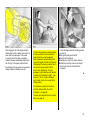
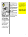
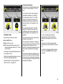
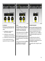
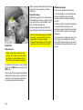
This symbol:
6 signifies: continue reading on next page.
3 The asterisk signifies equipment options not in all vehicles (model variants, engine options,
models specific to one country, optional equipment, Genuine Vauxhall Parts and Accessories).
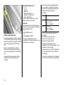
Tex t highlighted in yellow in particular indicates possible risk of accident and injury.
Disregard of these notes can lead to injuries which may be fatal.
Vehicle passengers must be informed accordingly.
We wish you many hours of pleasurable driving
Your Vauxhall team
2
RHD Vaux
Contents
Commitment to customer
satisfaction:
Our aim: to keep you happy with your vehicle.
All Vauxhall Dealerships offer first class
service at competitive prices. Experienced,
factory-trained technicians work according to
factory instructions. Y our dealership can
supply you with GENUINE VAUXHALL
APPROVED P ARTS, which have undergone
stringent quality and precision checks, and of
course useful and attractive VAUXHALL
APPROVED A CCESSORIES.
Our name is your guarantee!
For detai ls of the
Vauxhall Dealership Network
pl ease ring this number 01582 - 427200
In Brief ........................................................ 4
Instruments ............................................... 26
Keys, Doors, Bonnet ................................ 50
Seats, Interior ........................................... 63
Safety Systems ........................................ 78
Lighting ................................................... 118
Windows, Sun Roof ................................ 122
Electronic air conditioning system ......... 126
Automatic Transmission ......................... 134
Driving hints ............................................ 140
Saving Fuel ............................................. 142
Environmental P rotection ...................... 144
Fuel Consumption,
Fuel, Refuelling ................................... 146
Catalytic Converter, Exhaust Emissions 148
Drive Control S ystems ............................ 152
Brakes .................................................... 159
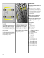
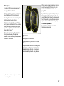
Wheels, Tyres ......................................... 164
Roof Rack s,
Caravan and Trailer Towing ................ 168
Self-Help ................................................. 174
If you have a problem.............................. 196
Maintenance, Inspection System .......... 198
Vehicle Care ........................................... 209
Technical Data ........................................ 213
Index ........................................................ 232
3
4
In Brief
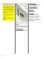
Key numbers,
Code numbers
Remove key number from key.
The key number is given in the vehicle
documents and in the Car Pass 3.
Alloy wheels 3, tow ing equipment 3: make a
note of the key identifier codes.
Electronic immobilizer, radio 3: the code
numbers are given in the Car P ass and Radio
Pass 3 respectively.
Do not keep the Car Pass and Radio P ass in
the vehicle.
6 Further information – see pages 50, 51,
Vehicle recommissioning – see page 208.
4
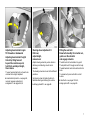
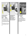
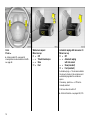
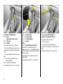
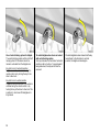
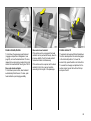
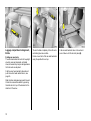
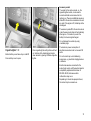
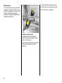
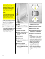
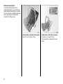
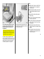
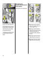
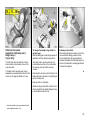
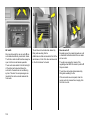
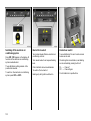
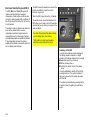
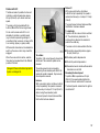
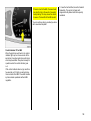
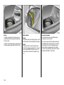
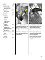
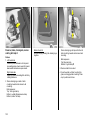
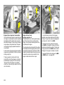
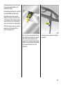
Unlocking the vehicle:
Direct remote control unit towards
vehicle,
press button q,
raise door handle
To unlock manually: turn key in lock and raise
door handle.
To lock doors from inside: press lock buttons.
6 Door locks, child safety lock – see page 50,
electronic immobilizer – see page 51,
radio remote control – see page 52,
central locking system – see page 54,
anti-theft locking system – see page 55,
Vauxhall alarm system 3 – see page 59.
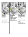
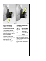
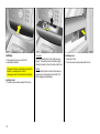
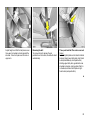
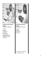
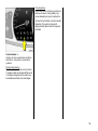
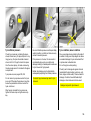
Adjusting the seats:
Pull handle, move seat,
release handle,
lock seat audibly in position
Never adjust the driver's seat whilst driving.
It could move in an uncontrolled manner
when the handle has been pulled.
6 Seat position – see page 63,
electrically adjustable seats – see page 66.
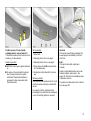
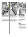
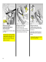
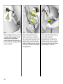
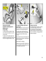
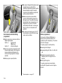
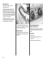
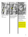
Adjusting seat backrests:
Turn handwheel
Move seat backrest to suit seating position.
Do not lean on seat when adjusting.
6 Seat position – see page 63,
electrically adjustable seats – see page 66.
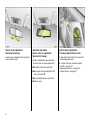
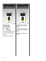
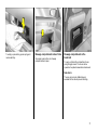
Adjusting the seat inclination 3:
Raise handle, adjust inclination,
release handle,
lock seat audibly in position
Never adjust the inclination of the driver's seat
whilst driving. The seat could move in an
uncontrolled manner when the handle has
been raised.
6 Seat position – see page 63,
electrically adjustable seats – see page 66.
5
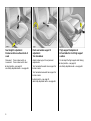
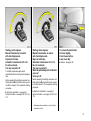
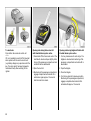
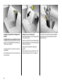
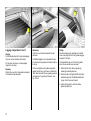
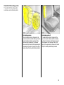
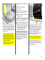
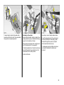
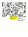
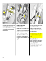
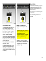
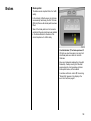
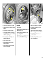
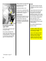
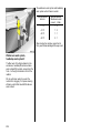
Seat height 3 adjustment:
Rocker switch on outboard side of
seats
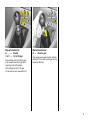
Front seat lumbar support 3
adjustment:
Turn handwheel
Thigh support 3 adjustment:
Lift and slide the front thigh support
cushion.
Raise seat:
Lower seat:
Adjust lumbar support to suit personal
requirements.
Do not adjust the thigh support whilst driving.
Press rocker switch up
Press rocker switch down
6 Seat position – see page 63,
electrically adjustable seats – see page 66.
Turn handwheel forwards: more support for
lumbar column.
Turn handwheel rearwards: less support for
lumbar column.
6 Seat position – see page 63,
electrically adjustable seats – see page 66.
6
6 Seat position – see page 63,
electrically adjustable seats – see page 66.
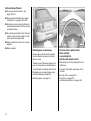
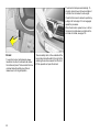
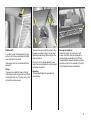
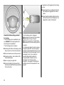
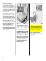
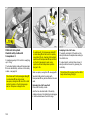
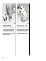
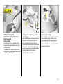
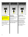
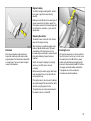
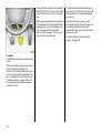
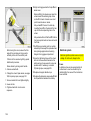
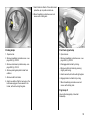
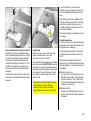
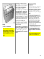
Adjusting head restraint angle:
Tilt forwards or backwards
Adjusting head restraint height:
Unlock by tilting forward
beyond the resistance point,
hold firmly and adjust height,
then release
Steering wheel adjustment 3:
Pull lever,
adjust height,
release lever
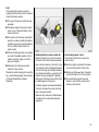
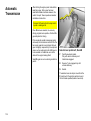
Fitting the seat belt:
Draw belt smoothly from inertia reel,
guide over the shoulder
and engage in buckle
Adjust steering wheel only when vehicle is
stationary and steering column lock is
released.
The rear head restraints do not need to be
unlocked to be height-adjusted.
The steering wheel can be set to five different
positions.
The belt must not be twisted at any point.
The lap belt must fit snugly across the body.
The seat backrest must not be inclined too far
back.
6 Head restraint position – see page 64,
removal, luggage compartment
enlargement – see pages 64, 65.
Set steering wheel to highest position to
facilitate entering and leaving the vehicle.
6 A irbag systems 3 – see page 86.
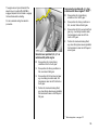
To release belt, press red button on belt
buckle.
6 Seat belts – see pages 78 to 84,
airbag systems 3 – see page 86.
7
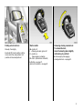
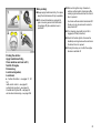
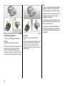
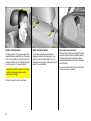
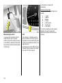
Interior mirror adjustment:
Swivel mirror housing
Swivel lever on underside of mirror housing to
reduce dazzle at night.
Automatic anti-dazzle
interior mirror 3, adjustment:
Swivel mirror housing
Dazzle is automatically reduced at night.
The mirror does not reduce dazzle when:
z the ignition has been switched off,
z reverse gear has been selected or shift
lever is in position R,
z interior lighting has been switched on,
z a door is open.
8
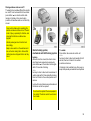
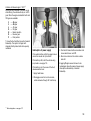
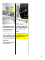
Exterior mirror adjustment:
Four-way switch in driver’s door
Toggle switch to left or right: four-way switch
moves appropriate mirror.
6 Further information, aspherical exterior
mirror 3 – see page 117,
heated exterior mirrors – see page 18,
position memory – see page 67.
Folding exterior mirrors:
Starter switch:
Manually: P ress lightly.
o = Ignition off
I = Steering unlocked, ignition off
II = Ignition on,
diesel engines: preheating
III = Start – (transmission in Neutral!)
Electrically 3: Press the button until the
mirrors reach their end positions. Not
possible with manual adjustment.
Releasing steering column lock:
To release the lock,
move the steering wheel slightly
and turn key to position I
6 Removing k ey and engaging
steering wheel lock – see page 23.
6 Starting – see page 21,
electronic immobilizer – see page 51.
9
10
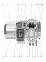
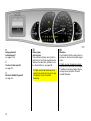
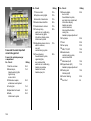
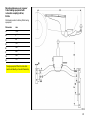
1
Page
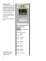
Side air vents ..................................... 18
10
2
Front passenger airbag 3 ................. 86
11
3
Centre air vents .............................. 128
4
Electronic air conditioning system . 126
Instrument illumination .....................120
Fog tail lamp......................................119
Fog lamps 3 .....................................119
Headlamp range adjustment 3 .........118
5
Display for time, date,
radio 3,
check control 3,
trip computer 3
infotainment system 3 ...................... 32
12
Release lever for bonnet ................... 62
13
Storage compartment
14
Accelerator pedal .................... 140, 141
15
Starter switch with
steering column lock (not visible) ........ 9
16
Brake pedal .......................... 159 to 163
17
Clutch pedal .................................... 141
18
Fuse box ..........................................185
6
Horn ................................................... 16
7
Turn signals, headlamp flash,
dipped and main beam ............... 14, 15
Cruise control buttons 3 .................157
8
Instruments ........................................ 26
9
Windscreen wipers and wash system,
headlamp wash system 3 and
rear window wash system 3 ....... 16, 17
Trip computer 3 ................................ 42
Page
Light switch ................................14, 120
P age
19 Seat heating (right) 3 ...................... 132
Vauxhall alarm system 3 .................. 59
Traction Control System 3 ............. 152
or Electronic S tability Program 3 ... 154
Boot lid/tailgate 3 ............................. 57
20 Ashtray with cigarette lighter ...... 75, 76
21 Radio 3
or infotainment system 3 .................. 47
22 Seat heating (left) 3 ........................ 132
Hazard warning lights ....................... 15
Rear window blind 3 ....................... 125
23 Glove compartment
with telematic unit 3 ......................... 48
11
Control indicators
O
Turn signal lamps:
see pages 15, 26.
!
Preheating system 3:
see page 26.
W
Coolant temperature 3:
see page 26.
g
Tr ailer turn signal 3:
see page 26.
X
v
=
v
Airbag systems 3,
belt tensioner s:
see pages 81, 89.
Traction Control System 3:
see page 152.
Electronic Stabi lity Program 3:
see page 154.
R
Brake system,
clutch system:
see page 28, 204.
Seat belt 3:
see page 26.
p
Alternator:
see page 28.
u
Anti-lock brake system 3:
see page 162.
>
Fog lamps 3:
see pages 29, 119.
Z
Exhaust emission 3:
see pages 26, 150.
r
Fog tail lamp:
see pages 29, 119.
1
Automatic transmission 3,
sporty driving programme:
see page 136.
Y
Fuel l evel:
see pages 29, 174.
?
Automatic headlamp
range adjustment 3,
fault:
see page 119.
F
Brake pad wear i ndicator 3:
see pages 29, 159.
y
Seat occupancy recognition 3:
see page 90.
P
Main beam:
see pages 14, 26.
I
Oil pressure:
see page 27.
A
Engine electronics,
transmission el ectronics 3,
immobilizer 3:
see pages 27, 51, 150.
12
Lighting
Light switch,
lev er posi tions:
see pages 14, 118,
7
8
9
Lights off
0
Courtesy lamp:
see page 119.
>
Fog lamps 3:
see page 119.
r
Fog tail lamp:
see page 119.
k
Instrument ill umination:
see page 120.
?
Headlamp range adjustment:
see page 118.
¨
Hazard warning lights:
see page 15.
Parking lamps
Dipped and main beam
Electronic air conditioning,
seat heating
Sun Roof
Miscellaneous
l
p
Demisti ng and de-icing
Air distribution to windscreen
and front door window s.
Sun roof 3:
closing – see page 124.
Central locking system 3:
lock ing – see page 54.
ü
q
x
Sun roof 3:
opening – see page 124.
Central locking system 3:
unlocking – see page 54.
Air flow:
see page 131.
q
r
t
Sun roof 3:
raising – see page 124.
Boot lid/tailgate 3:
unlocking – see page 56.
Air circul ation system:
see page 129.
x
Luggage compar tment 3:
unlocking – see page 56.
)
Cigarette lighter :
see page 75.
j
Horn:
see page 16.
V
Air distr ibution:
see page 131,
Windscreen wipers
Lev er positi ons:
see page 16,
K
to foot area
§
$
%
&
Fast
Ä
Ü
Heated rear window:
see page 130.
Vauxhall alarm system:
see page 59.
Date, time, radio
/
Bonnet:
see page 62.
T
Winter programme,
automatic transmission 3:
see page 136.
+
Fir st-aid kit 3:
see pages 178, 179.
¨
Warning tr iangle 3:
see pages 178, 179.
N
Rear wi ndow blind:
see page 125.
s
M
to windscreen
to head area above adjustable
air vents front and rear 3
AUTO Automatic mode:
see page 127.
ECO
Operation without cooling:
see page 130.
OFF
Switching off electr onic air
conditioning:
see page 132.
ß
Heated seats 3:
see page 132.
Off
Timed interval wipe
Slow
Information display 3:
see page 32,
Ö
;
On button for date and time
Set button for date and time
Steering wheel mounted remote
control 3:
see page 48.
13
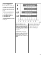
Light switch:
7 = Off
8 = Parking lamps
9 = Dipped or main beam
Main and dipped beam switch:
Main beam = Push lever forwards
Dipped beam = Pull lever towards
steering wheel
Pull 0
By overcoming the lever resistance the
headlamp flash is operated.
= Courtesy lamp
Push r = Fog tail lamp
6 Further information – see page 118,
headlamp warning device – see page 23,
headlamp range adjustment 3 – see page
118,
fog lamps 3 – see page 119,
daytime running lights – see page 118.
14
Headlamp flash:
Pull lever towards steering wheel
Operating turn signal lamps:
Lever in rest position
Right turn =
Upwards
Left turn
=
Downwards
When the steering wheel is turned back, the
lever automatically returns to its original
position. This will not happen when making a
minor steering manoeuvre such as changing
lane.
Operating parking lamps:
Key to position o,
Light switch to position 0,
Remove ignition key,
Move turn signal lever up or
down from rest position
Hazard warning lights:
On
= Press ¨
Off = Press ¨ again
To aid location of the pushbutton, the red
surface is illuminated with the ignition
switched on. When the button is pressed, its
control indicator flashes in time with the
hazard warning lights.
When lane changing, move lever part way, to
first stop. When released, lever will spring
back.
15
Horn:
Press j
6 Airbag systems 3 – see page 86,
steering wheel mounted remote control 3 –
see page 48.
Windscreen wipers:
Move lever up
§ = Off
$ = Timed interval wipe
% = Slow
& = Fast
Automatic wiping with rain sensor 3:
Move lever up
§ = Off
$ = Automatic wiping
with rain sensor
% = Slow (constant)
& = Fast (constant)
Automatic wiping $: The rain sensor detects
the amount of water on the windscreen and
automatically regulates the windscreen
wipers.
If necessary, positions % or & can be
manually selected.
Push lever down to switch off.
6 Further information – see pages 204, 210.
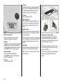
16
Operating windscreen and
headlamp wash systems 3:
Pull lever towards steering wheel
The headlamp wash system 3 can only be
operated when the lights are on: wash fluid is
sprayed onto the headlamps.
Operating rear window wiper and
wash systems 3:
Wiper on
= Push lever forward
Wiper off
= Pull lever towards
steering wheel
wash
= Push lever forward
and hold
In vehicles with rain sensor 3 operate
windscreen wash system at regular intervals
in order to keep sensor clean.
The rear window wiper operates in timed
interval mode. When washing, the wipers
swipe at a constant pace as long as the lever
is pressed forward.
The wipers will wipe for a few strokes.
6 Further information – see page 206.
6 Further information – see pages 206, 211,
212.
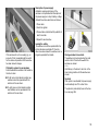
17
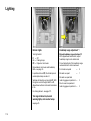
Heated rear window,
heated exterior mirrors:
On
= Press Ü
Off = Press Ü again
The rear window and exterior mirror heating
is switched off automatically after approx.
15 minutes.
6 Further information – see page 130.
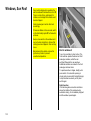
18
To clear misted or icy windows:
Press V
Open front air vents, direct side air vents
towards the door windows. Close centre air
vents 3.
6 Electronic air conditioning system – see
page 126.
Manual transmission:
o
= Neutral
1 to 5 = 1st to 5th gear
When shifting up from 4th to 5th gear:
push the lever towards the right at the
beginning of the shift operation.
Manual transmission:
R = Reverse gear
Only engage reverse gear when the vehicle is
stationary. This is done by pulling up the ring
below the shift knob.
When shifting from 5th to 4th gear:
do not exert any force towards the left.
19
Automatic transmission 3:
P = Park
(with selector lever lock)
R = Reverse
N = Neutral
Engine may be started only in P or N.
To move out of P switch on ignition, press
foot brake and pull release under selector
lever.
To engage P or R pull release on selector
lever.
P:
R:
Only with vehicle stationary, first
apply hand brake
Only with vehicle stationary
6 Automatic transmission – see page 134.
20
D =
3 =
2 =
1 =
Plus:
S =
1st
1st
1st
1st
to 4th gear
to 3rd gear
and 2nd gear
gear
Sporty driving programme
Select 3, 2 or 1 if certain gears are not
desired, e.g. 4-3-4 . . . on winding roads, or in
order to utilize the engine braking effect when
driving downhill.
To engage 3 or 1 pull the release on the
selector lever.
6 Automatic transmission – see page 134.
Lock to prevent unintentional
selection of position P, R, 3 or 1:
Pull release under selector lever:
1, P: up to final stop.
Do not pull release when selecting any
position in the direction from 1 to N or from R
to D.
6 Automatic transmission – see page 134.
Starting, petrol engines:
Manual transmission: in neutral
with clutch depressed,
Depress foot brake,
Automatic transmission: in P or N,
Do not accelerate,
Turn key to position III
The initially increased engine speed
automatically falls as the engine temperature
rises.
Starting, diesel engines:
Manual transmission: in neutral
with clutch depressed,
Depress foot brake,
Automatic transmission: in P or N,
Do not accelerate,
Turn key to position II,
When the preheating control indicator
goes out1) ,
turn key to III
Before repeating the starting procedure, turn
the key back to o in the starter switch, remove
it and then reinsert it. Then repeat the starting
procedure.
Before repeating the starting procedure, turn
the k ey back to o in the starter switch, remove
it and then reinsert it. Then repeat the starting
procedure.
6 Electronic immobilizer – see page 51,
further information – see pages 140, 142, 144,
174.
6 Electronic immobilizer – see page 51,
further information – see pages 140, 142, 144,
174.
1)
To release the hand brake:
Lift lever slightly,
Push release button,
Lower lever fully
6 Brakes – see page 159.
Preheating system swit ches on only if outside
temperature is low.
21
Before driving off check:
z Tyre pressures and condition – see
pages 165, 225.
z Engine oil level and fluid levels in engine
compartment – see pages 199 to 206.
z All w indows, mirrors, exterior lighting and
number plates are free from dirt, snow and
ice and operational.
z Do not place any objects in front of the rear
window, on the instrument panel or in the
area in which the airbags inflate.
z Seats, seat belts and mirrors are correctly
adjusted.
z Brake operation.
Exhaust gases are poisonous
Ex haust gases contain carbon monoxide,
which is extremely poisonous but has no
odour or colour.
And now, have a good journey!
Drive carefully,
economically and
with the environment in mind
Therefore never inhale ex haust gases, and
never run the engine in an enclosed space.
While driving, do not do anything that could
distract you.
You should also avoid driving with the boot
lid/tailgate open, as exhaust gases could
enter the passenger compartment.
Take heed of the traffic reports given out on
the radio.
6 Exhaust gases – see page 151.
22
6 Driving hints – see page 140,
saving fuel – see page 142,
environmental protection – see page 144.
When parking:
z Always apply hand brake firmly. On slopes
apply the hand brake as firmly as possible.
z With manual transmission, engage first
gear or reverse gear and with automatic
transmission 3, place selector lever in
position P.
z Remove the ignition key, otherwise in
vehicles with automatic transmission 3 a
warning signal will sound when the driver's
door is opened.
In vehicles with automatic transmission 3
the key can only be removed in selector
lever position P.
z Turn steering wheel until lock is felt to
engage (anti-theft protection).
z Switch off exterior lights, otherwise the
headlamp warning device will sound when
the driver's door is opened.
z Cooling fans may run on after the engine
has been switched off.
Parking the vehicle:
Apply hand brake firmly,
Close windows and sun roof 3,
Switch off engine,
Remove key,
Lock steering wheel,
Lock doors
6 Further information – see pages 51, 141,
161,
radio remote control – see page 52,
central locking system – see page 54,
Vauxhall alarm system 3 – see page 59,
vehicle decommissioning – see page 208.
23
Genuine Vauxhall Parts and
Accessories
We recommend that you use Genuine
Vauxhall Parts and A ccessories and
conversion parts released expressly for your
vehicle type. These parts have undergone
special tests to establish their reliability,
safety and specific suitability for Vauxhall
vehicles. Despite continuous market
monitoring, we cannot assess or guarantee
these attributes for other products, even if
they have been granted approval by the
relevant authorities or in some other form.
Service, Maintenance
Your Vauxhall Dealership can provide you
with reliable service. All work is correctly
performed according to factory instructions.
6 Vauxhall S ervice – see page 196.
24
"Genuine Vauxhall Parts and Accessories"
and approved conversion parts are available
from your Vauxhall Dealership, who can
advise you on any point, including permissible
technical modifications, and carry out correct
installation.
For your safety
Carry out regularly the checks
recommended in the individual sections of
this Owner's Manual.
Ensure that your vehicle is serviced by a
Vauxhall Dealership as specified in the
Service Booklet.
Have faults remedied without delay by a
Vauxhall Dealership! If necessary, interrupt
your journey.
6 Maintenance – see pages 198 to 207.
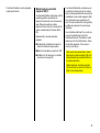
That was a brief overview.
Please read on!
6
Your vehicle has still more
instruments and controls,
possibly also optional
equipment.
6
You will also find further
important information on
operation, safety and
maintenance and
a complete index.
6
25
Instruments
!
Preheating 3 (diesel engine)
Control indicator lights up during preheating.
Preheating system switches on only if outside
temperature is low.
W
Coolant temperature
If it lights up when the engine is running:
Stop the vehicle and switch off the engine.
Coolant temperature is too high: Switch off
the engine. Danger to engine. Coolant
temperature gauge; see page 31. Check
coolant level immediately; see page 203.
g
Z
Exhaust emission 3
Control indicator lights up when ignition is
switched on. Goes out shortly after engine
starts.
If it lights up when the engine is running:
Fault in the emission control system. The
permissible emission limits may be exceeded.
Consult a Vauxhall Dealership immediately.
If it flashes when the engine is running:
Fault which may damage the catalytic
converter – see page 150. Consult a Vauxhall
Dealership immediately.
1
The control indicators described here are not
present in all vehicles. The description applies
to all instrument versions.
Tr ailer turn signal 3
Control indicator flashes in time with turn
signal lamps when towing. Does not flash if a
turn signal lamp on the towing vehicle or
trailer fails.
Automatic tr ansmission electronically
controlled drive programmes 3
Control indicator lights up when sporty driving
programme operative.
O
X
P
Control indicators
Turn signal lamps
The control indicator flashes when the turn
signal is activated. Rapid flashes: A turn
signal bulb has failed. Changing bulbs, see
page 188.
Seat bel t 3
Control indicator lights up (accompanied by
an acoustic warning): Fasten your seat belt.
u
Anti-lock brake system 3
see page 162.
26
Further information – see page 136.
Main beam
Control indicator lights up when main beam is
on and when headlamp flash is operated.
I
Oil pr essure
Control indicator lights up when ignition is
switched on. Goes out shortly after engine
starts. Can light up intermittently when idling
with hot engine; must go out when engine
speed is increased.
If it lights up when the engine is running:
Engine lubrication may be interrupted. This
may result in damage to the engine and/or
locking of the drive wheels:
1. Depress clutch.
2. Move gearshift lever to neutral, or with
automatic transmission 3 place selector
lever in N.
3. Navigate out of moving traffic as quickly as
possible without impeding other vehicles.
4. Switch off the ignition (position I ).
When the ignition is off, considerably more
force is needed to brake and steer.
Do not remove key until vehicle has come
to a standstill, otherwise the steering
column lock could engage unexpectedly.
Consult a Vauxhall Dealership.
A
Engine electronics, transmission
electronics, immobiliz er
Control indicator lights up for a few seconds
when ignition is switched on.
If it lights up when the engine is running:
Fault in the engine electronics or transmission
electronics system. The electronic system
switches to an emergency running
programme. Fuel consumption may be
increased and the driveability of the vehicle
may be impaired; see page 150. If there is a
fault in the transmission electronics system,
switch to manual gears; see page 138.
Consult a Vauxhall Dealership.
If it flashes when the ignition is on:
Fault in the electronic immobilizer system; the
engine cannot be started – see page 51.
27
v
Ai rbag systems 3,
bel t tensioners 3
see pages 81, 89.
=
Traction Control system 3
see page 152.
v
Electronic Stabili ty Program 3
see page 154.
28
R
p
Brake system,
clutch system
Control indicator lights up when ignition is
switched on if hand brak e is applied and/or
fluid level for brake/clutch hydraulics is too
low. Brake fluid level – see page 204.
Alternator
Control indicator lights up when ignition is
switched on. Goes out shortly after engine
starts.
If it lights up when the hand brake is not
applied: stop vehicle; interrupt your journey
immediately. Consult a Vauxhall
Dealership.
If it lights up when the engine is running:
Stop the vehicle and switch off the engine.
The battery is not being charged. Engine
cooling may be interrupted. Consult a
Vauxhall Dealership.
>
Fog lamps 3
Control indicator lights up when fog lamps are
switched on.
r
Fog tail lamp
Control indicator lights up when fog tail lamp
is switched on.
Y
Fuel level
If it lights up: fuel is at reserve level.
If it flashes: fuel used up, fill up immediately.
?
Fault in automati c headlamp range
adjustment system 3
Control indicator lights up when ignition is
switched on. Goes out after a few seconds. If
it lights up when driving, a fault has occurred.
Consult a Vauxhall Dealership immediately –
see page 119.
F
Brake pad wear indicator 3
If it lights up when the engine is running: Front
disc brake pads worn down to minimum
thickness. Consult a Vauxhall Dealership to
have the brake pads replaced – see page 159.
Never let the tank run dry!
Diesel engines: if the tank becomes empty, a
complicated procedure is necessary to bleed
the fuel system. Consult a Vauxhall
Dealership – see page 174.
y
Seat occupancy recognition 3,
see pages 90, 91.
29
Tachometer 31)
Speedometer1 )
Odometer
Indicates engine speed.
Indicates the vehicle speed.
Records the miles/kilometres driven.
Warning: permitted maximum speed
exceeded, engine at risk
1)
30
The instruments in your vehicle may differ from
the instruments illustrated here.
Trip odometer
To return to zero, depress reset knob.
For physical reasons, the engine temperature
gauge shows the coolant temperature only if
the coolant level is adequate.
During operation the system is pressurized.
The temperature may therefore rise briefly to
over 100 °C.
Coolant temperature gauge
Fuel gauge
Pointer in
low zone
Pointer in red
warning zone or
Y lit
=
Pointer
between the
zones
=
Engine operating
temperature not yet
reached
Fill up,
see page 147.
Never let the tank run dry!
=
Pointer in
red warning
zone or W is lit =
Normal operating
temperature
Temperature too high.
S top vehicle
and switch off engine.
Danger to engine,
check coolant level
immediately see
page 203.
Diesel engines: The fuel system is difficult to
bleed if the tank has been allowed to run dry;
see page 174.
On account of the fuel remaining in the tank,
the amount filled may be less than the
specified tank capacity.
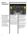
31
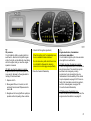
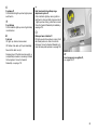
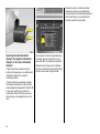
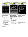
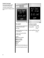
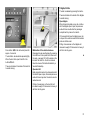
Information display
Triple information display
Display of time, outside temperature and
radio/date.
The time and outside temperature are
displayed w hen the ignition is on. The date is
displayed when the radio 3 is off.
When the ignition is off, the time, date and
outside temperature can be displayed for
15 seconds by briefly pressing one of the two
buttons above the display.
--.- °C or an F in the display indicates a fault.
Have the cause remedied by a Vauxhall
Dealership.
32
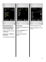
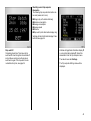
Multi -information display 3
Display of date, radio 3 / date, outside
temperature, check control, trip computer.
The display operates when the ignition is
switched on. Time is continually displayed
while the date is displayed when the radio is
off.
When the ignition is off, the time, date and
outside temperature can be displayed for
15 seconds by briefly pressing one of the two
buttons above the display or the button on the
wiper lever.
An F in the display indicates a fault. The
function in question is rendered inoperative.
Have the cause remedied by a Vauxhall
Dealership.
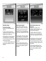
Multi-informati on display for r adio
telephone 3
Display of time, radio/date, outside
temperature, telephone information, check
control 3 and trip computer 3.
The display operates when the ignition is
switched on. Time is continually displayed
while the date is displayed when the radio is
off.
When the ignition is off, the time, date and
outside temperature can be displayed for
15 seconds by briefly pressing one of the two
buttons above the display or the button on the
wiper lever 3.
An F in the display indicates a fault. The
function in question is rendered inoperative.
Have the cause remedied by a Vauxhall
Dealership.
Interruption of power supply
After a power supply interruption or low
battery voltage the electronic radio disabler 3
and date and time must be reset.
See radio operating instructions for how to
disable electronic block. Entering date and
time, see 38.
Upon receipt of a time signal from an RDS
transmitter 1) , date and time are set
automatically 3; see page 38.
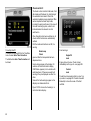
Graphical information display 3,
Colour information display 3
Display of date, time, outside temperature,
and information from check control 3, trip
computer 3 and infotainment system.
The information displayed depends on the
vehicle equipment and the settings of the trip
computer 3 and the infotainment system.
F or Safe in the display indicates a fault. Have
the cause remedied by a Vauxhall Dealership.
The graphical information display presents
the information in monochrome. The colour
information display presents the information
in colour.
1)
RDS = Radio Dat a S yst em.
33
Operation using the multifunction button:
Individual menu items are highlighted by
turning the button and selected by pressing it.
Press the BC button on the infotainment
system to open the trip computer.
Operating the multi-information
display 3, the graphical information
display 3 or the colour information
display 3
These functions are operated using the
buttons on the wiper lever or, on vehicles with
infotainment system 3, by using the
multifunction button.
If check control issues a warning message,
the display is block ed from other functions.
Ack nowledge the message with button S or R
on the wiper lever 3 or by pressing the
multifunction button 3. If there are several
fault warnings, acknowledge them one at a
time.
34
Trip computer functions are operated using
the display menu and the buttons on the
wiper lever 3 or the infotainment system 3.
Operation using the wiper lever: Individual
functions are selected using button S. Certain
functions can be reset using button R.
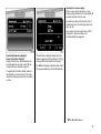
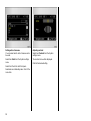
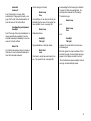
Making system settings for the
graphical information display 3 or
the colour information display 3
Language sel ection
You can select the display language for some
functions.
The figures show execution with the colour
information display.
Select menu item Instructions from the
system settings menu.
In the trip computer menu Settings select
System Settings.
The list of available languages will be
displayed.
Select the desired language from the list.
Selections are indicated by a 6 in front of the
menu item.
The system settings menu will be displayed.
35
Setting units of measur e
You can select which units of measure are to
be used.
Adjusting contrast
Select item Contrast from the S ystem
settings menu.
Select item Units from the S ystem settings
menu.
The contrast menu will be displayed.
Select from the list of units that opens.
Selections are indicated by a 6 in front of the
menu item.
36
Confirm the desired setting.
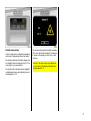
Outside temperature
A fall in temperature is indicated immediately
and a rise in temperature after a time delay.
On vehicles with triple information display, the
symbol T is shown in the display from 3 °C as
a warning for icy road surfaces.
On vehicles with multi-information display 3,
outside temperature is automatically shown in
the display from 3 °C.
On vehicles with graphical information display
3 or colour information display 3, a message
is shown in the display to warn for icy road
surfaces.
Caution: The road surface may already be
icy even though the display indicates a few
degrees above 0 °C.
37
Setting date and time
In the infotainment system 3, time and date
are set automatically upon receipt of GPS
satellite signals1 ). If the time displayed does
not correspond to the local time, it can be set
manually in 30- minute steps or be corrected
automatically via an RDS time signal2) .
For the radio, time and date can be set
manually or corrected automatically via an
RDS time signal 3.
The automatic setting is indicated by Ö in the
display.
Vehicles with triple information display or
multi -information display 3
Manual setting
Switch off radio. Press Ö and ; above the
display as follows:
Press Ö for approx. 2 seconds:
Day flashes
Press ;: S et day
1)
GPS = G lobal P ositioning System,
2)
Satellit e system for global positioning.
RDS = Radio Data Syst em.
38
Press Ö:
Press ;:
Month flashes
S et month
Press Ö:
Press ;:
Y ear flashes
S et year
Press Ö:
Press ;:
Hours flash
S et hours
Press Ö:
Press ;:
Minutes flash
S et minutes
Press Ö:
Clock is started
Deactivating and activating automatic
setting 3
Press Ö for approx. 2 seconds; the time
display is now in setting mode.
Press Ö
twice ( until year flashes).
Press Ö
for approx. 3 seconds until } in
display flashes and the display
"RDS TIME" appears (years flash
while button is depressed).
Press ;
Display indicates:
RDS TIME 0 = Deactivated
RDS TIME 1 = Activated
Press Ö
three times.
Vehicles with graphical information
di splay 3 or colour information di splay 3
With the infotainment system on, date and
time can be set with buttons Ö and ; above
the display:
Ö
for approx. 3 seconds until the menu for
date and time setting appears.
Ö
Move about the menu.
;
Change or confirm the setting. To
activate the settings, select OK.
Date and time can also be set using the
infotainment system:
In the trip computer menu Settings select
item System S ettings and then item Time/
Date.
The Time/Date menu will be displayed.
Select the desired menu item.
Mak e the desired settings and confirm.
Select OK.
39
Check control 3
The check control monitors fluid levels, front
disc brake pad thickness, the functioning of
the automatic transmission 3 and the
automatic headlamp range adjustment 3 as
well as important exterior lamp bulbs,
including the wiring and fuses. In the case of
the bulb monitoring system, a fault is not
indicated unless the relevant circuit is
switched on.
Once the ignition has been switched on, all
check control functions are automatically
verified.
If all the monitored functions are OK, the
warning
Correcting time 3
To correct the time, use RDS in the Time/Date
menu to select Auto. Time Correction.
The field behind Auto. Time Correction will
be ticked.
Brake Lamp
Check
goes out after the brake pedal has been
depressed once.
Fault w arnings appear in the display. On
vehicles with multi-information display,
CHECK also appears ( not on vehicles with
radio telephone). If there are several fault
warnings, they are displayed one after the
other.
Some of the fault warnings appear on the
display in an abbreviated form.
Figure 7570 V shows a fault warning in a
multi-information display.
40
Fault warnings:
Engine Oil
Level
Engine oil level too low. Check oil level
immediately and top up oil – see page 200.
Coolant
Level
Coolant level in ex pansion tank too low. Top
up coolant – see page 203. Consult a Vauxhall
Dealership to have the cause of the fault
rectified.
Automatic
Gearbox 3
Fault: Transmission no longer shifts
automatically. Change gear manually – see
page 138. Consult a Vauxhall Dealership to
have the cause of the fault rectified.
Headlamp Range Adjustment
Headlight
Fault: The range of the xenon headlamps is no
longer automatically regulated. Consult a
Vauxhall Dealership immediately to have the
cause of the fault rectified.
Brake Pad
Front disc brak e pad worn down to minimum
thickness. Consult a Vauxhall Dealership to
have the brak e pads replaced.
Fault w arnings (continued)
Brake Lamp
Fuse
Fuse defective. A new fuse should only be
installed after the cause of the trouble has
been rectified. Fuses – see page 186.
Acknowledge the fault warning as indicated
on page 34. After acknowledgement, the
warning will be cleared from the display.
The fault warnings
Brake Lamp
and
Brake Lamp
Fuse
Brake Lamp
Brake lamp failure.
Headlight
Tail Light
Dipped headlamp or tail lamp failure.
Wash Fluid
Lev el
Fluid level in windscreen wash system too
low. Top up wash fluid – see page 206.
and
Headlight
Tail Light
reappear 15 minutes after they have been
acknowledged.
After the ignition has been switched off and
switched on again, the stored fault warnings
appear on the display one after the other.
Once the faults have been remedied, the fault
warnings are automatically erased.
41
Interruption of power supply
Check control automatically checks all
functions after the battery has been
reconnected or charged. S tored fault
warnings appear on the display one after the
other.
Trip computer 3
The trip computer shows vehicle data which it
continually records and evaluates
electronically.
Some of the functions appear on the display
in an abbreviated form.
The figures show the version with multiinformation display.
Functions:
z Instantaneous consumption
z Average consumption
z Absolute consumption
z Average speed
z Distance
z Range
z Stop watch (multi-information display only).
Check control warnings always have priority.
42
Instantaneous consumption
Display changes depending on speed:
Display in gal/h (l/h)
below 8 mph
(13 km/h)
Display in mpg ( l/100 km) above 8 mph
(13 km/h)
Av erage consumption
Calculation of average consumption. The
measurement can be re-started at any time;
see page 34.
Absolute consumption
Shows the amount of fuel consumed. The
measurement can be re-started at any time;
see page 34.
Aver age speed
Calculation of average consumption. The
measurement can be re-started at any time;
see page 34.
Stoppages in the journey with the ignition off
are not included in the calculations.
43
Distance
Shows the number of miles (kilometres)
travelled. The measurement can be re-started
at any time; see page 34.
Range over 30 miles (50 km)
The range is calculated from the current
contents of the fuel tank and the average
consumption over the last 12 to 20 miles
(20 to 30 km) of the journey.
After filling up the vehicle, the range adjusts
itself automatically after a short time. It can
also be adjusted manually; see page 34.
44
Range bel ow 30 mi les (50 km)
If the fuel in the tank will allow less than
30 miles (50 k m) of travel, the warning
"Range" appears in the display.
Resetti ng current trip computer
information
The following trip computer information can
be reset (values set to zero):
z
z
z
z
z
z
Range (only with vehicle stationary)
Absolute consumption
Average consumption
Average speed
Distance
Stop watch (multi-information display only)
Vehicles with multi-information display: P ress
button R; see page 34.
Stop watch 3
Calculating travel time: The stop w atch is
switched off when the ignition is switched off
and continues running once the engine is
switched on again. The stop watch can be
re-started at any time; see page 34.
Vehicles with graphical information display 3
or colour information display 3: Select the
desired item from the trip computer menu.
Then select menu item S ettings.
The Trip computer-Settings menu will be
displayed.
45
Resetti ng multiple infor mation on the trip
computer
The following trip computer information can
be reset simultaneously (values set to zero):
z
z
z
z
z
Absolute consumption
Average consumption
Average speed
Distance
Stop watch (multi-information display only)
Vehicles with multi-information display: P ress
button R for at least 2 seconds.
In the Trip computer-Settings menu, select
item BC r eset curr ent values.
The value for the selected function w ill be
reset and recalculated.
The value for Range can only be reset when
the vehicle is stationary.
After resetting, the trip computer information
may show "- - -" for the selected item. A fter a
short time, actual values will be shown again.
46
Vehicles with graphical information display 3
or colour information display 3: In the Trip
computer-Settings menu, select item BC
reset all current values.
The values will be reset and "***" will be
displayed. New values can only be calculated
when the engine is running. You must drive a
short distance before average speed can be
calculated.
z Changes in distance from the transmitter,
z multi-path reception due to reflection and
z shadowing
may cause hissing, noise, distortion or loss of
reception altogether.
Interruption of power supply
If the power supply has been interrupted or if
the battery voltage has dropped too low, the
values stored in the trip computer will be lost.
Radio 3
The radio is operated as described in the
operating instructions supplied.
The display for the radio appears on the
information display.
Car radio reception will differ from reception
possible with domestic radios:
As the vehicle aerial is relatively near the
ground, the broadcasting companies cannot
guarantee the same quality of reception as is
obtained with a domestic radio using an
overhead aerial.
47
Infotainment system 3
The infotainment system is operated as
described in the operating instructions
supplied.
The telematic unit 3 ( telephone) is in the glove
compartment.
48
Electronic data acquisition in toll
systems
Steering wheel mounted remote
control 3
On vehicles w ith heat-reflectant windscreen 3, mount the chip card for electronic
data acquisition and billing in the black
shaded zone of the windscreen on the left or
the right behind the interior mirror. If the chip
card is mounted outside this zone,
malfunctions may occur in data acquisition.
Radio 3, radio telephone 3 and infotainment
system 3 functions can be operated w ith the
buttons on the steering wheel.
For further information, see the respective
operating instructions.
Mobile telephones and radio
equipment (CB) 3
The Vauxhall installation instructions and the
operating guidelines provided by the
telephone manufacturer must be observed
when fitting and operating a mobile
telephone. Failure to do so could render the
vehicle unroadworthy (EU Directive 95/54/
EG ).
Requirements to ensure trouble-free
operation:
z Professionally installed exterior aerial to
obtain the maximum range possible
z Max imum transmission pow er from 10 W
z Installation of the telephone in a suitable
spot (see note on page 92).
Your Vauxhall Dealership can advise you on
permissible mounting spots for the exterior
aerial or radio equipment holder as well as the
possibilities for use of radio equipment (CB)
with transmission power greater than 10
watts. Various brackets and mounting kits are
available as accessories to ensure proper
installation.
Use a handsfree attachment if you must use
your phone while driving. Even with a
handsfree attachment, the telephone could
distract you from the traffic situation. Follow
the national regulations of the country in
which you are driving.
When used in the vehicle interior, mobile
telephones and radio equipment (CB) with
integrated aerial may cause malfunctions in
the vehicle electronics.
Mobile telephones and radio equipment
(CB) should only be used with an antenna
fitted on the vehicle exterior.
49
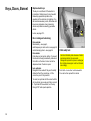
Keys, Doors, Bonnet
Replacement keys
The key is a constituent of the electronic
immobilizer. Ordering k eys from a Vauxhall
Dealership guarantees problem- free
operation of the electronic immobilizer. You
will avoid unnecessary costs, difficulties with
insurance companies when processing
claims and problems asserting guarantee
claims.
Locks, see page 212.
Door locking and unlocking
From outside:
Mechanically – see page 5,
radio frequency remote control – see page 52,
central locking system – see page 54.
From inside:
Push down or pull up lock button. To prevent
the driver from being inadvertently locked out,
the button on the driver's door cannot be
depressed when the door is open.
Lock cylinders
Designed to free-wheel if they are forcefully
rotated w ithout the correct key or if the
correct key is not fully inserted.
To reset, turn cylinder with the correct until its
slot is vertical, remove key and then re-insert
it. If cylinder still free-wheels, turn the key
through 180° and repeat operation.
50
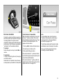
Child safety lock
Use the child safety lock whenever children
are transported on the rear seats.
Disregard may lead to injuries or endanger
life. Vehicle passengers must be informed
accordingly.
Push latch on rear door lock downwards:
Door cannot be opened from inside.
Electronic immobilizer
Protects the vehicle from theft by means of an
electronic system which prevents the engine
from being started. The system checks
whether the vehicle may be started using that
particular key. Only if the k ey is recognised as
"authorised" can the vehicle be started.
To activate:
Switch off engine, turn key to position o and
remove.
To deacti vate:
Turn key to position II (ignition on); the engine
can then be started.
Deactivation is not possible in any other way,
so keep spare key accessible in a safe place!
Control indicator for immobil izer
When the ignition is switched on, the control
indicator A lights up briefly. If the control
indicator flashes when the ignition is on, there
is a fault in the immobilizer system. The
engine cannot be started:
1. Turn k ey to o in starter sw itch and remove.
2. Re-insert key into starter switch.
3. then repeat starting procedure.
Note
The immobilizer does not lock the doors.
Therefore, after leaving the vehicle always
lock it and switch on the Vauxhall alarm
system 3; see pages 54, 59.
The Car Pass contains all of the vehicle's data
and therefore must not be kept in the vehicle.
Have your Car Pass ready to hand when
consulting a Vaux hall Dealership.
If the control indicator A continues to flash,
try to start the engine using the spare key and
consult a Vauxhall Dealership.
If the control indicator A lights up after the
engine has been started, there is a fault in the
engine electronics – see page 150.
51
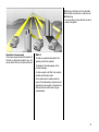
Radio remote control 3
The radio remote control is integrated in the
key.
Used to operate:
z central locking system,
z mechanical anti-theft locking system,
z boot lid (Saloon),
z Vauxhall alarm system 3.
It is also possible to close the windows and
sun roof 3 using the remote control unit.
The remote control has a range of approx.
3 metres. The range may be reduced owing to
shadowing and reflection of the radio waves.
To operate the remote control, point it at the
vehicle.
52
For your convenience, we recommend that
the central locking system always be
operated using the remote control unit.
Handle remote control with care, protect from
moisture and high temperatures and avoid
unnecessary operation.
The light-emitting diode (LED) in the remote
control unit lights up and the hazard warning
lights flash briefly to show that the remote
control is operational.
Central locking system,
see page 54.
Mechanical anti-theft locking system,
see page 55.
Boot lid/tailgate 3,
see page 56.
Vauxhall alarm system 3,
see page 59.
Fault
If the central locking system cannot be
operated with the remote control, this may be
due to the following reasons:
z The range of the remote control has been
exceeded.
z The battery voltage of the remote control
unit is too low. Change the battery in the
remote control unit.
z The remote control has been operated frequently in succession outside the vehicle's
reception range ( e.g. at too great a distance
from the vehicle). Resynchronize the
remote control.
z If the central locking system is overloaded
as a result of repeated operation at short
intervals, the power supply is cut off for
approx. 30 seconds.
z Interference from higher-power radio
waves from other sources.
Operate the central locking system using the
key – see the following pages. Have the cause
of the fault eliminated by a Vauxhall
Dealership.
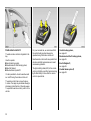
Replacing battery in remote control uni t
Replace the battery as soon as the range of
the remote control starts to become reduced.
Sy nchroniz ing r emote control
In the event of malfunctions, synchronize
remote control:
Insert a small screwdriver in the notch on the
cover and prise it open. Disengage the remote
control from the key part and open the battery
cover. Replace the battery, ensuring that it is
inserted correctly (see page 227 regarding
battery type). Close the remote control so that
it audibly engages in the key part.
z Switch on ignition; system will then remain
in synchronizing mode for 30 seconds.
The battery change must be performed w ithin
3 minutes, otherwise the remote control will
have to be resynchronized.
z Briefly press button p or q on the remote
control unit while the unit is in the ignition.
z The central lock ing system locks and
unlocks to show that the remote control
has been synchronized.
Make sure that you dispose of old batteries in
accordance with environmental protection
regulations.
53
Note
To prevent the driver from being inadvertently
locked out, the button on the driver's door
cannot be depressed when the door is open.
If the driver's door is not closed properly, the
central locking system will unlock again
immediately after locking.
To lock the doors from the inside (e.g. when
stopped at traffic lights), press down the lock
button on the driver's door.
Locked doors are unlocked automatically in
the event of an accident ( to allow assistance
from outside), provided that the ignition is not
switched off.
Central locking system 3
For doors, boot lid/tailgate and tank flap.
To lock:
Press button p on remote control unit
– or –
turn key in driver's door lock towards rear of
vehicle, then turn it back to the vertical
position and remove; alternatively, when
locking from inside, press the lock button on
one of the front doors with the doors closed.
54
To unlock:
Press button q on remote control unit
– or –
turn key in driver's door lock towards front of
vehicle, then turn it back to the vertical
position and remove; alternatively, when
unlocking from inside, pull up the lock button
on driver's door.
Closing windows and sun roof 3
The electric door windows 3 and the electric
sun roof 3 can be closed from the outside:
press button p on remote control while
locking or hold key in the door locking
position until window s and sun roof are fully
closed.
Care must be taken when operating the
electric windows and the sun roof. There is
a risk of injury, especially for children, and
a danger that articles could become
trapped.
Vehicle passengers must be informed
accordingly.
Keep a close watch on the windows and
sun roof when closing them. Ensure that
nothing becomes trapped in them as they
move.
Central locking system,
mechanical anti-theft locking system
Locking
All doors must be closed, the driver’s door
must have been opened once previously;
press button p on the remote control again
within 10 seconds of lock ing
– or –
turn key in driver's door lock towards rear of
vehicle again within 10 seconds after locking,
then turn it back to the vertical position and
remove.
To unlock:
Press button q on remote control unit
– or –
turn key in driver's door lock towards front of
vehicle, then turn it back to the vertical
position and remove.
Unlocking is not possible in any other way, so
keep the spare key accessible in a safe place!
Lock buttons on all doors are positioned such
that doors cannot be opened.
Do not use the system if there are people in
the vehicle! The doors cannot be unlock ed
from inside.
55
Malfunction of the central locking
system
e.g. if vehicle battery is flat.
A = Unlocking the driver's door
Turn k ey in driver's door lock towards
front of vehicle, turning it beyond its
resistance point until it will not move any
further. Turn key back to vertical position
and remove; raise door handle. Lock button remains in depressed position.
B = Locking the driver's door
With driver's door closed, turn key
towards rear of vehicle until it will not
move any further. Turn key back to vertical position and remove.
The other doors can be opened and closed by
pulling or pushing the inner lock button (not
possible if anti-theft mechanism enabled
beforehand). Have cause of fault remedied by
a Vauxhall Dealership.
56
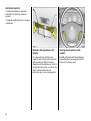
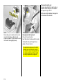
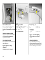
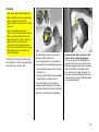
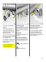
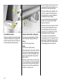
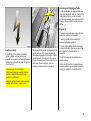
Opening the tank flap
Unlock and open the boot lid/tailgate. O pen
the cover on the right-hand side of the
luggage compartment. The release rod for the
tank flap is located behind the servo motor
(arrow in figure). Push the rod back with your
hand and the tank flap can be opened. Have
the cause of the fault remedied by a Vauxhall
Dealership.
Overload
If the central locking system is overloaded
as a result of repeated operation at short
intervals, the power supply is cut off for
approx. 30 seconds.
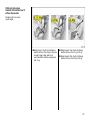
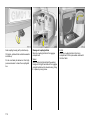
Boot lid, Saloon
To unlock:
Press button r on the remote control
– or –
Tailgate, Estate
The lock is released by pressing the button.
There is a handle on the inside of the tailgate
to assist closing.
Open tailgate
When transporting bulk y cargo, do not drive
with the tailgate open or ajar, as poisonous
ex haust fumes could enter the passenger
compartment by means of air whirls.
If it is essential to have the tailgate open, do
not open it too wide to ensure that the number
plate can still be read.
Press button x in the instrument panel for
approx. 2 seconds.
The boot lid is unlocked and opened slightly.
When the boot lid is open the LED in the
button x is lit.
There is a handle on the inside of the boot lid
to assist closing.
Mal function of the electrical release
Disengage the rear seat backrest by pressing
the buttons on the top and fold it down onto
the seat – see page 70. Pull the cable on the
inside of the boot lid – the lid is unlock ed.
Have the cause of the fault eliminated by a
Vauxhall Dealership.
Fitting of accessories on the tailgate will
increase its weight. If it becomes too heavy, it
will then not stay open.
6
Open boot lid
Bulky objects should not be transported with
the boot lid open or ajar, otherwise poisonous
exhaust fumes may enter the vehicle as air is
swirled around.
Fitting of accessories on the boot lid will
increase its weight. If it becomes too heavy, it
will then not stay open.
57
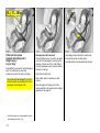
Use of central locking system for tai lgate
The central locking system and the anti-theft
locking system for the doors cannot be
locked or unlocked from the tailgate lock.
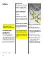
Key slot in lock in horizontal position
Tailgate is locked and unlocked using the
remote control or by turning the key in the
driver's door lock.
Key slot in lock in vertical position
Tailgate remains locked even if the vehicle is
unlocked using the remote control or by
turning the key in the driver's door lock. This
position is to be chosen if the tailgate is to
stay locked.
58
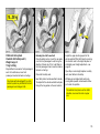
To unlock tailgate when doors are locked
with central locking system
Turn key clockwise from vertical or horizontal
position as far as it will go. To guard against
being locked out, the key cannot then be
removed.
Once the tailgate has been closed and the key
turned back to the horizontal or vertical
position, the tailgate is lock ed again.
Vauxhall alarm system 3
The system monitors
z the doors, luggage compartment, bonnet,
z the passenger compartment,
z the vehicle tilt,
z the ignition.
To activate:
All doors, windows and sun roof 3 must be
closed; press button p on the remote control
unit again within 10 seconds after locking
– or –
turn key in driver's door lock towards rear of
vehicle again within 10 seconds after locking,
then turn it back to the vertical position and
remove.
Switching on without monitoring of the
passenger compartment and the vehicle
tilt
e.g. if animals are to be left in the vehicle.
1. Close boot lid/tailgate and bonnet.
2. Press button Ä. LED flashes (for a maximum of 10 seconds); see page 61.
3. Close doors.
4. Switch on Vauxhall alarm system. LED
lights up. After approx. 10 seconds the system is activated, without monitoring of the
passenger compartment or vehicle tilt. LED
flashes until system is switched off.
6
59
To deacti vate:
Press button q on remote control unit
– or –
If it is not possible to switch off the Vaux hall
alarm system with the remote control unit
(e.g. battery voltage low), open doors with the
key. The alarm which has been triggered is
terminated shortly after switching on the
ignition.
60
Opening and closing Saloon boot li d
with Vauxhall alarm sy stem active
Opening and closing tailgate of Estate with
Vauxhall alarm system active
1. Press button r on the remote control. The
boot lid will unlock and open slightly. Monitoring of the passenger compartment and
vehicle tilt will be deactivated.
1. Turn key clockwise as far as it will go. The
tailgate is unlocked and monitoring of the
passenger compartment and vehicle tilt is
deactivated.
2. Open the boot lid.
2. Open the tailgate.
3. Monitoring of the passenger compartment,
luggage compartment and vehicle tilt is
switched on again approx . 10 seconds
after the boot lid is closed.
3. Close the tailgate.
4. Turn the key back to its previous position.
Monitoring of the passenger compartment,
luggage compartment and vehicle tilt is
activated after approx. 10 seconds.
After the first 10 seconds of Vaux hall alarm
system activation:
z LED flashes
=
System on
z LED lights up for
approx. 1 second
=
Switch-off
If a system fault occurs, consult a Vaux hall
Dealership. The system's integral selfdiagnosis facility allow s faults to be quickly
remedied.
Alarm
Only a certain number of alarms are allowed
to be triggered while the Vauxhall alarm
system is switched on (this number is
stipulated by law).
The alarm takes the form of
z an acoustic signal (horn, 30 seconds) and
z a visual signal (hazard warning lights,
5 minutes)1) .
The alarm can be stopped by switching off
the Vauxhall alarm system or by pressing
button p on the remote control unit.
Alarm siren with intergrated battery 3
Light-emitting diode (LED)
During the first 10 seconds of Vauxhall alarm
system activation:
z LED lights up = Test, switch-on delay
z LED flashes
= Door, tailgate,
bonnet open
or system fault
The alarm siren monitors the on-board
voltage network and triggers an alarm if this
netw ork is manipulated ( e.g. if the vehicle’s
battery is disconnected by unauthorised
persons). The alarm siren has its own power
supply and is therefore not dependent on the
vehicles battery.
If the vehicles battery is to be disconnected
(e.g. for maintenance work), the alarm siren
must be deactivated as follows: switch the
ignition on then off, disconnect the vehicle’s
battery within 15 seconds.
To switch off alarm siren:
Switch ignition on then off.
1)
Varies from country to co untry on account of
nat ional regulations.
61
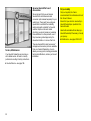
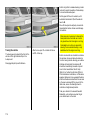
The bonnet is held open automatically. To
close the bonnet, lower it slowly and allow it
to fall into the lock under its own weight.
Check that the bonnet is locked in position by
pulling at its front edge. If it is not engaged,
repeat the procedure.
When the bonnet is opened, snow or dirt on
the bonnet can slide down and obstruct the
air intake. Air intake, see page 133.
Bonnet
To open the bonnet, pull release lever /,
located on the driver's outboard side below
the instrument panel. The bonnet will then be
unlocked and will partially open. Return
release lever to its original position.
62
There is a safety catch on the underside of the
bonnet about a handbreadth to the right of the
radiator grille centre as viewed from the front:
lift this upwards and open the bonnet.
Seats, Interior
Seat adjustment
see pages 5, 6.
Adjusting the seat position to suit the
occupant
Adjust driver's seat such that with the driver
sitting upright the steering wheel is held in the
area of its upper spok es with the driver's arms
slightly bent.
The passenger seat should be as far back as
possible, with the back rest upright.
Disregard can lead to injuries which could
be fatal. Vehicle passengers must be
informed accordingly.
63
Head restraint position
Head restraints, Saloon
The ideal position for the upper edge of the
head restraint is level with the top of the head.
If this is not possible for very tall people, the
restraint should be set to its highest position;
for short people, to its lowest position.
To fold down passenger seat backrest
(luggage compartment enlargement – see
page 68), remove head restraint. To do so,
release the two springs by pressing them and
detach the head restraint.
Disregard can lead to injuries which could
be fatal. Vehicle passengers must be
informed accordingly.
Setting, see page 7 and the next page.
64
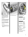
Rear centre head restraint 3
If the centre rear seat is unoccupied, the head
restraint can be removed to improve visibility.
Release both springs by pressing, detach
head restraint and place it in boot on left-hand
wheel housing.
The centre head restraint must be fitted if the
centre rear seat is occupied.
Head restraints, Estate
To fold dow n the passenger seat backrest
(Luggage compartment enlargement, see
page 70), remove the head restraint. To do so,
release the two springs by pressing them and
detach the head restraint. See Figure 7353 V.
Rear outer head restraints
To fold dow n: press button, head restraint
automatically folds forward. To raise, push
head restraint up and engage audibly.
Rear centre head restraint
If the centre seat is unoccupied, the head
restraint can be pushed all the way down to
improve visibility. Push the head restraint
forward and down simultaneously.
Centre armrest 3
If the centre seat is occupied, set the head
restraint to the first or second position
according to the height of the passenger.
To access the stowage compartment in the
centre armrest, press the button at the top
and open the lid.
The armrest can be raised. When folded down
from the raised position the armrest engages
in the horizontal position. To lower the
armrest fully: press the button on the bottom.
65
Electrically adjustable front seats 3
To adjust inclination at rear:
move switch 1 upwards/downwards at rear.
Care must be taken when operating the
electrically adjustable seats. There is a risk
of injury, particularly for children, and a
danger that articles could become trapped.
To adjust longitudinal position:
move switch 1 forwards/back wards.
To adjust height:
move switch 1 up/down.
Keep a close watch on the seats when
adjusting them.
To adjust backrest:
move switch 2 forwards/back wards.
Vehicle passengers must be informed
accordingly.
Operate switch until desired seat position is
reached. Seat position – see page 63.
Before leaving the vehicle, remove the
ignition key.
After adjusting the seat, adjust height of seat
belt – see page 82.
Adjustment
The seat position can be adjusted by means
of switches on the outboard side of the seats.
To adjust inclination at front:
move switch 1 upwards/dow nwards at front.
66
Position memory 3 for electri cally
adjustable driver’s seat and mirrors 3
Three different seat and mirror setups can be
stored (e.g. for three drivers).
Storing settings:
Ready for operation:
3. Adjusting exterior mirrors, see page 8.
z With driver's door open or ignition switched
on.
4. Press memory button M and position button 1 simultaneously.
z For approx. 30 seconds after the driver's
door has been closed or the ignition
switched off. Operational readiness is
prolonged if system is operated within
these 30 seconds.
5. Set position buttons 2 and 3 in the same
way.
1. Adjust seat.
2. Adjusting interior mirror, see page 8.
Retrieving settings:
Press and hold down position button 1, 2 or 3
until the stored seat and mirror positions 3
are set.
Ov erload
If the system is electrically overloaded, the
power supply is automatically cut off for a
short time.
Fault
If the electric drive fails, adjust seats
manually.
Adjust in longitudinal direction using crank
handle included in vehicle tools – see
pages 179, 180. I nsert crank handle as shown
in illustration and turn.
The system is protected by a fuse in the fuse
box; see page 184.
For reasons of safety, adjustment stops
immediately if the position button is released
or one of the setting buttons is operated.
67
Luggage compartment enlargement,
Saloon
Folding down the cover behind the armrest
Fold down the centre armrest onto the seat
cushion, turn the handle anti- clockwise and
tilt the cover forwards.
The outer seats can continue to be used for
passengers.
After repositioning, lock cover in position by
turning handle.
68
Folding the r ear seat backrests
Place the belt buckles in the storage pockets
in the seat cushions.
Unlock one or both of the rear seat backrests
using the pushbuttons on top and fold it down
onto the seat cushion.
Engage rear seat backrests audibly into
position.
When repositioning rear seat backrest, pull
seat belt forward so that it is not trapped.
In vehicles with centre three-point seat belt 3:
press button (on left-hand belt buckle). Belt
will retract fully.
Notes on loading
see page 74.
Folding the front passenger seat 3
Remove the head restraint; see page 64.
Fold front passenger seat forward by raising
release lever.
Engage the front passenger seat backrest
audibly into position.
Lashing eyes
These enable cargo to be secured in position
in the luggage compartment using lashing
straps 3 or a luggage net 3. The luggage net
can be adapted to secure small items of
luggage: fold over ends of net, guide hooks
through mesh and attach hooks to eyes.
69
Luggage compartment enlargement,
Estate
The catch slides completely to the left and a
red marking becomes visible.
Folding rear seat rests
The outer head restraints must not be upright
when the rear seat backrests are folded
down, otherwise they may be damaged when
the front seats are adjusted.
Unlock one or both of the rear seat backrests
using the pushbuttons on top.
Fold the outer head restraints forward and
push the centre head restraint down; see
page 65.
Slide the driver and passenger seats forward.
Unlock the rear seat backrests by pressing
the slide catch on top of the backrest in the
direction of the arrow.
70
Fold rear seat backrest down onto seat and
press it down until it locks into place (A).
To reposition: Slide driver and passenger
seats slightly forward. Press the back rest
down firmly (A), unlock it (B), and place it
upright.
Before repositioning the rear seat backrest,
make sure that the red marking on the slide
catch on top of the back rest is visible; see
page 70, Figure 13455 V.
When repositioning rear seat backrest, pull
seat belt forward so that it is not trapped.
Folding the front passenger seat 3
Remove the head restraint; see page 64.
When repositioning, lock the rear seat
backrests audibly into place on both sides by
pressing the slide catch on top of the
backrest in the direction of the arrow. The
catch slides back to its centre position and
the red marking is no longer visible.
Fold front passenger seat forward by raising
release lever.
Engage the front passenger seat backrest
audibly into position.
Notes on loading
see page 74.
Lashing eyes
These enable cargo to be secured in position
in the luggage compartment using lashing
straps 3 or a luggage net 3. The luggage net
can be adapted to secure small items of
cargo: fold over the ends of the net, guide the
hooks through the mesh and attach the hooks
to the eyes; see page 69, Figure 7344 V.
71
Luggage compartment cover 3
Closing
Pull the handle back to its stop and engage
the cover in the retainers at the sides.
Do not place any heavy or sharp-edged
objects on the cover.
Openi ng
Detach the cover from the retainers and push
it towards the seat backrest.
Removing
Push the cover forward towards the seat
backrest.
Pull folded-together cover towards the rear
into the two short guides on the rails as far as
it will go.
Pull cover together with guides rearwards
against spring force, as shown in illustration.
Twist the cover with the two guides upwards
and remove it by pushing it forw ard – see
Fig. 7532 V.
Fitting
Reverse sequence of operations to reinstall
cover, ensuring that the short guides engage
properly in the rails.
If individual ribs slip out of the short guides
when the cover has been removed:
1. Detach all ribs from the two guides by
pressing the locking devices.
2. Insert the ribs in the right and left-hand rails
simultaneously with the flattened ends facing up. P ush the cover forward.
3. Insert short guides in rails from below
against spring force.
72
Safety net 3
The safety net can be fitted behind the rear
seats or, with the rear seat backrest folded
down, behind the front seats.
There are two eyes under the carpet in the
luggage compartment and in the rear seat
backrests respectively: attach straps in the
eyes and tension.
Passengers must not be carried behind the
safety net.
If the net is to be installed behind the rear
seats, the rear seat backrest must be upright
and locked in position.
Fitti ng
There are two installation holes in the roof
frame: O pen covers using ignition key. Attach
net (working from one of the rear doors), lock
in position and close covers.
Removing
Tilt strap length adjusters upwards and
unhook strap.
Stowage of safety net
Roll up the safety net and secure it with
Velcro. Unlock the rear seat backrests by
depressing the pushbuttons and tilt them
forward slightly. S uspend the safety net (in its
protective cover) in the recesses on the right
and left behind the rear seat backrest.
73
z Do not place any objects in front of the rear
window or on the instrument panel. They
are reflected in the glass, obstruct the
driver's view and will be thrown through the
vehicle, for instance in the event of heavy
brak ing.
z No objects must be placed in the area in
which the airbags inflate, as they could
cause injury when the airbags are triggered.
z Bulk y objects should not be transported
with the tailgate/boot lid open. Otherwise,
poisonous ex haust fumes could enter the
vehicle. In addition, the number plate is
only clearly distinguishable and correctly lit
if the tailgate is closed.
Notes on loading the vehicle
z Heavy objects in the luggage compartment
should be placed as far forward as possible
against the rear seat backrests or, if the
rear seat backrests are folded down,
against the front seat backrests. If objects
are to be stacked, the heavier objects
should be placed at the bottom. Unsecured
objects in the luggage compartment would
be thrown forward with great force in the
event of heavy brak ing, for example.
z Secure heavy objects with lashing straps 3
attached to lashing eyes – see page 69.
If heavy loads slip when the vehicle is
braked heavily or driven around a bend, the
handling of the vehicle may change.
z Saloon: Loose objects in the luggage
compartment should be secured against
slipping using a luggage net – see page 69.
z Estate: Always fit the safety net when
transporting objects in the luggage
compartment; see page 73.
z If objects are being transported in the
luggage compartment, the rear seat
back rests must be locked in place 3 (red
marking on the slide catch on top of the
back rest no longer visible) ; see
pages 68, 71.
z Do not allow the load to protrude above the
upper edge of the rear seat backrests, or
above the upper edge of the front seat
back rests if the rear seat backrests are
folded down.
z The warning triangle 3 and first-aid kit 3
must always be freely accessible.
74
z Weights, payload and roof load – see
page 222.
z Driving with a roof load (see pages 140,
143, 168) increases the sensitivity of the
vehicle to crosswinds and has a
detrimental effect on vehicle handling due
to the vehicle’s higher centre of gravity.
Disregard of these instructions may lead to
injuries or endanger life. Vehicle
passengers must be informed accordingly.
Accessory socket
The socket in the centre console, i.e. the
cigarette lighter socket, can be used to
connect electrical accessories when the
ignition is on. There is an additional accessory
socket 3 in the centre console below the rear
air vents. If the engine is off, the battery will be
discharged.
The accessory socket 3 in the centre console
under the rear air vents shuts off automatically
after approx. 15 minutes to prevent the
battery from becoming discharged.
Do not damage the sockets by using
unsuitable plugs.
Cigarette lighter ) 3
Behind ashtray cover below tray or radio 3.
Press ashtray cover to open.
Press cigarette lighter with ignition switched
on. Switches off automatically and ejects
when element is glow ing. Withdraw cigarette
lighter.
The maximum power consumption of
electrical accessories must not exceed 120
watts.
Do not connect any current-delivering
accessories, e.g. electrical charging devices
or batteries.
Electrical accessories connected to the
socket must comply with the electromagnetic
compatibility requirements laid down in
DIN VDE 40 839, otherwise vehicle
malfunctions may occur.
Depending on the vehicle equipment level,
the socket may be covered over.
75
Ashtrays
To be used only for ash and not for
combustible rubbish.
Disregard of these instructions may lead to
injuries or endanger life. Vehicle
passengers must be informed accordingly.
Ashtray, front
The cover opens when pressed at the top.
76
To empty
Push the small catch to the right (arrow in
figure). The ashtray insert will raise slightly.
Grasp the insert by the trim plate and lift out.
Fitting
Insert ashtray insert and lock into place by
pressing on surfaces at left and right. The
latch engages automatically.
Ashtrays, rear
In rear door trims.
The cover opens when pressed at the top.
To empty: open ashtray, press spring and
remove ashtray.
Stowage compartments in door trims
To access press button on stowage
compartment and open.
Stowage compartments in the
backrests
To open, pull back the compartment cover
using the grip recess. The cover can be
opened or be pulled rearwards and removed.
Sun visors
The sun visors can be folded down or
swivelled to the side to prevent dazzling.
77
Safety Systems
Three-stage restraint system
Comprising:
z three-point seat belts
z belt tensioners on the front seats
z airbag systems for driver and front
passenger 3.
The three stages are activated in sequence
depending on the seriousness of the
accident:
z The automatic seat belt locking devices
prevent the belt strap from being pulled out
and thus ensure that the vehicle occupants
are retained in their seats.
z The front seat belt buckles are pulled
downwards. As a result, the seat belts are
instantaneously tightened and the
occupants are made aware of the
deceleration of the vehicle at a very early
stage. This reduces the stress placed on
the body.
z The airbag systems are also triggered in the
event of serious accidents and form a
safety cushion for the occupants.
78
The airbag system serves to supplement
the three-point seat belts and belt
tensioners. The seat belts must therefore
always be worn. Disregard of these
instructions may lead to injuries or
endanger life. Vehicle passengers must be
informed accordingly.
Be sure to read the detailed descriptions of
the three- stage restraint system and the child
restraint system on the following pages!
Seat belts
Alw ays wear your seat belt, and that means
also in urban traffic and when you are a rear
seat passenger. It can save your life!
Pregnant women must alw ays wear a seat
belt, see page 82.
In the event of an accident, persons not
wearing seat belts endanger their fellow
occupants and themselves.
Control indicator X for seat belts, see
page 26.
Seat belts are designed to be used by only
one person at a time. They are only suitable
for children aged up to 12 or smaller than
150 cm if used in conjunction with a child
seat.
For children up to 12 years of age we
recommend the Vauxhall child restraint
system – see page 94.
Three-point seat belts
The vehicle is equipped with three-point seat
belts with automatic retractors and locking
devices, allowing freedom of body movement
although the spring tensioned belts always
ensure a snug fit.
The belt has a "vehicle sensitive retractor"
which is designed to lock during heavy
acceleration or deceleration in any direction.
79
The seat belts remain fully operational even
when the belt tensioners have been actuated.
Belt tensioners
The front seat belt system incorporates belt
tensioners. I n the event of a head-on or tailend collision, depending on the severity of the
accident, the belt buckles are pulled
downwards; the diagonal and lap belts are
instantaneously tightened.
Further information – see page 84.
Actuation of belt tensioners
is indicated by the control indicator v
Actuation may also be indicated by yellow
tabs on the belt buckles.
Once the belt tensioners have been actuated,
they must be replaced by a Vauxhall
Dealership.
80
In case of a fault have the systems checked
without delay by a Vauxhall Dealership.
The system's integral self-diagnosis facility
allows faults to be quickly remedied. Have
your Car Pass ready to hand when consulting
a Vauxhall Dealership.
Important
z Accessories not released for your vehicle
type and other objects must not be affixed
or placed within the action zone of the belt
tensioners since this may result in injury if
the belt tensioners are triggered.
Control indicator v for belt tensioner s
Belt tensioners are electronically monitored
together with the airbag systems. Their
operational status is indicated by control
indicator v in the instrument panel. When the
ignition is switched on, the control indicator
lights for approx. 4 seconds. I f it does not
light up, if it does not go out after 4 seconds
or if it lights up while driving, there is a fault in
the belt tensioner system or in the airbag
systems; see page 89. The belt tensioners or
airbag systems could fail to be triggered in an
accident.
z Do not mak e alterations to the seat belt
tensioner components, since this would
render the vehicle unroadworthy.
z The electronics controlling the belt
tensioners and the airbag systems are
located in the centre console. To prevent
malfunctions, no magnetic objects should
be placed in the immediate vicinity of this
console.
z Have the front seats removed by a Vauxhall
Dealership.
z The belt tensioners actuate once only.
Actuated belt tensioners should be
replaced by a Vauxhall Dealership.
z The Vauxhall safety directives must alw ays
be observed when disposing of the vehicle.
For this reason, disposal should be
performed by a Vauxhall Dealership.
If handled improperly the pyrotechnic seat
belt tensioners can be triggered in an
ex plosive manner - risk of injury!
81
Using the belts
Fitti ng the belt
Pull the belt out of the retractor and guide it
across the body, making certain that it is not
twisted.
Insert the latch plate into the buckle. The seat
backrest must not be tilted back too far or the
seat belt will not operate properly. The
recommended angle of inclination is 25°.
Make sure that the lap belt is not twisted and
that it fits snugly across the body. Tension the
belt frequently while driving by tugging the
diagonal part of the belt.
82
The lap belt must be positioned as low as
possible across the pelvis so as not to put
too much pressure on the abdomen. This is
particularly important for pregnant women.
Bulky clothing prevents the belt from fitting
properly. The belt must not rest against hard
or fragile objects in the pockets of your
clothing (e.g. ballpoint pens, keys,
spectacles) because these could cause injury.
Do not place any objects (e.g. handbags)
between the belt and your body.
Height adjustment
of seat belt upper anchorage point:
1. Pull belt out slightly.
2. Front seat belts: Press button down or slide
belt guide up.
Rear seat belts: Press belt guide and slide
it upwards or downwards.
3. Set desired height.
4. Allow anchorage to lock audibly into
position.
Do not adjust height while driving.
Adjust height such that the belt passes over
the w earer's shoulder and rests against the
shoulder. It must not pass over the neck or
upper arm.
Removing the belt
To remove the belt, depress the red
pushbutton on the buckle; the belt will retract
automatically.
Three-point seat belt 3 on centre rear seat
Saloon
Pull belt by latch plates out of retractor behind
backrest. Insert lower latch plate in left-hand
buckle (identifiable by small pushbutton).
Holding upper latch plate, guide belt across
shoulder and pelvis, making certain that it is
not tw isted, and insert latch plate in righthand buckle (red pushbutton).
6
83
To remove belt, depress red pushbutton on
belt buckle. The belt will retract automatically
and will position itself ready to hand on the
backrest.
To enlarge luggage compartment, depress
small pushbutton on left-hand buckle using a
ballpoint pen or similar object. The belt will
retract fully. Fold down backrests onto seat
cushion.
Lap belt
In centre of rear seat: to adjust the length,
press the top of the latch plate.
Estate
Draw belt out of retractor and guide across
shoulder and pelvis, making certain that it is
not twisted, and insert latch plate in belt
buckle.
Periodically inspect all parts of the belt
system for damage and to make sure they are
functioning properly. Have damaged parts
replaced. After an accident, overstretched
belts and actuated belt tensioners must be
replaced with new ones by a Vauxhall
Dealership.
The belt can only be pulled out of the retractor
when the rear seat backrests are properly
locked into position; see page 68.
Inspection of belts
Do not perform any alterations on the belts,
their anchorages, the automatic retractors or
the belt buckles.
Mak e sure that belts are not damaged or
trapped by sharp-edged objects.
84
Vauxhall Full Size airbag system
The Vauxhall Full Size airbag system
comprises several individual systems.
Front airbag system
The front airbag system is triggered in the
event of a serious accident involving a frontal
impact and forms safety cushions for the
driver and front passenger. The forward
movement of the driver and front passenger is
checked and the risk of injuries to the upper
body and head thereby substantially reduced.
Side airbag system 3
The side airbag system is triggered in the
event of side-on collisions and forms safety
cushions for the driver and front passenger in
the respective front door area. The risk of
injury to the upper body in the event of a side
impact is thereby substantially reduced.
85
Examples of events triggering the front airbag
system:
z Impact against a non-yielding obstacle: the
front airbags are triggered at low vehicle
speed.
z Impact against a yielding obstacle (such as
another vehicle): the front airbags are only
triggered at a higher vehicle speed.
Vauxhall Full Size airbag systems 3
Front airbag
The front airbag system is identified by the
word AIRBAG on the steering wheel and
above the glove compartment.
The front airbag system comprises:
z an airbag with inflator in the steering wheel
and a second one in the instrument panel
z the control electronics with impact sensor
z the airbag systems' control indicator v in
the instrument panel
z seat occupancy recognition 3
z the control indicator for Vauxhall child
restraint systems y with transponders 3 in
the courtesy lamp.
86
The front airbag system is triggered:
z depending on the severity of the accident
z depending on the type of impact
z within the range shown in the illustration
z independently of the side airbag system 3.
Ex ception:
Front passenger seat w ith a seat occupancy
recognition system 3. The seat occupancy
recognition system deactivates the front and
side airbags for the front passenger if the front
passenger's seat is not occupied or a
Vauxhall child restraint system with
transponders 3 is fitted on the front
passenger's seat. Seat occupancy
recognition – see page 90. Vauxhall child
restraint system with transponders 3 – see
page 94.
When triggered, the front airbags inflate in
milliseconds to form a safety cushion for the
driver and front passenger. The forward
movement of the front seat occupants is
checked, thereby substantially reducing the
risk of injury to the upper body and head.
No impairment of view will occur, because the
airbags inflate and deflate so quickly.
The front airbag system provides optimum
protection when the seat, backrest and
head restraint are correctly adjusted:
Adjust the driver's seat according to the
occupant's height such that with the driver
sitting upright the steering wheel is held in
the area of its upper spok es with the
driver's arms slightly bent. The front
passenger's seat should be as far back as
possible, w ith the backrest upright – see
pages 5, 5, 63. Do not place the head,
body, hands or feet on the covers of the
airbag systems.
The front airbag system will not be triggered in
the event of
z the ignition being switched off
z minor frontal collisions
z accidents in which the vehicle overturns
z collisions involving a side or rear impact
where it would not be of benefit to the
occupants.
6
Do not place any objects in the area in
which the airbags inflate. Important
information – see page 92.
The three-point seat belt must be correctly
fitted – see page 82.
87
Seat belts must therefore always be worn.
The front airbag system serves to
supplement the three-point seat belts. If
you do not wear your seat belt you risk
being seriously injured, or even thrown
from the vehicle, in the event of an
accident.
The belt helps to k eep you in the correct
seating position, in which the front airbag
system will provide you with effective
protection in the event of an accident.
In addition, the front airbag system will not be
triggered for the front passenger in versions
with seat occupancy recognition 3 if
z the front passenger's seat is unoccupied
z there is a properly fitted Vauxhall child
restraint system with transponders 3. S eat
occupancy recognition – see page 90.
Vauxhall child restraint system with
transponders 3 – see page 94.
Side airbag 3
The side airbag system is identified by the
word AIRBAG on the outboard sides of the
front seat backrests.
The side airbag system is triggered:
The side airbag system comprises:
z within the range show n in the illustration on
the driver's door or front passenger door
z an airbag with inflator in the back of the
driver's and front passenger's seat
respectively
z the control electronics
z the side impact sensors
z the airbag system’s control indicator v in
the instrument panel
z seat occupancy recognition 3
z the control indicator for Vaux hall child
restraint systems y with transponders 3 in
the courtesy lamp.
88
z depending on the severity of the accident
z depending on the type of impact
z independently of the front airbag system.
Exception:
Front passenger seat with a seat occupancy
recognition system 3. The seat occupancy
recognition system deactivates the front and
side airbags for the front passenger if the front
passenger's seat is not occupied or a
Vauxhall child restraint system with
transponders 3 is fitted on the front
passenger's seat. S eat occupancy
recognition – see page 90. Vauxhall child
restraint system with transponders 3 – see
page 94.
The side airbags will not be triggered in the
event of
z the ignition being switched off
z frontal collisions
z accidents in which the vehicle overturns
z collisions involving a rear impact
z collisions involving a side impact outside
the passenger cell.
In addition, the side airbag system will not be
triggered for the front passenger in versions
with seat occupancy recognition 3 if
z the front passenger's seat is unoccupied
When triggered, the side airbag inflates in
milliseconds to form a safety cushion for the
driver or front passenger in the respective
door area. This substantially reduces the risk
of injury to the upper body in the event of a
side-on collision.
There must be no objects in the area in
which the airbag inflates or in the area
between the seat backs and the vehicle
body. Do not place the hands or arms on
the covers of the airbag systems. Important
information, see page 92.
The three-point seat belt must always be
correctly fitted – see page 82.
z there is a properly fitted Vauxhall child
restraint system with transponders 3. Seat
occupancy recognition – see page 90.
Vauxhall child restraint system with
transponders 3 – see page 94.
Control indicator v for airbag systems
The front airbag system and the side airbag
system 3 are monitored electronically
together with seat occupancy recognition 3
and the belt tensioners. Their operational
readiness is shown by control indicator v in
the instrument panel.
When the ignition is switched on, the control
indicator lights up for approx. 4 seconds. If it
does not light up, if it does not go out after
4 seconds or if it lights up during driving, there
is a fault in the airbag systems, the seat
occupancy recognition 3 or the belt
tensioners – see page 81. The systems may
fail to be triggered in an accident.
In case of a fault have the systems checked
without delay by a Vauxhall Dealership.
The system's integral self-diagnosis facility
allows faults to be quick ly remedied. Have
your Car Pass ready to hand when consulting
a Vauxhall Dealership.
89
Seat occupancy r ecognition 3
The seat occupancy recognition system
deactivates the front and side airbags for the
front passenger if the front passenger's seat
is not occupied or a Vauxhall child restraint
system with transponders 3 is fitted on the
front passenger's seat.
The control indicator for seat occupancy
recognition is located in the courtesy lamp.
If this control indicator lights up after the
ignition is switched on for approx. 4 seconds,
the vehicle is equipped with seat occupancy
recognition – see page 91, Fig. 11383 T.
This control indicator lights up permanently
after the ignition is switched on when a
Vauxhall child restraint system with
transponders 3 is fitted as soon as the
system has detected the seat. Only then can
the child restraint system be transported on
the front passenger's seat.
90
In addition, vehicles with seat occupancy
recognition can be identified by the sticker on
the front passenger seat – see Fig. 12154 V.
Vauxhall child restraint systems with
transponders 3 are detected automatically
when fitted on the front passenger's seat
according to the instructions. When using
these child restraint systems on the front
passenger's seat, the front and side airbag
systems for the front passenger's seat are
deactivated. Be sure to pay attention to
the seat occupancy recognition control
indicator 3 – see page 91.
Only Vauxhall child restraint systems with
transponders 3 can be fitted on the front
passenger seat; the use of systems without
transponders poses a danger to life.
Vauxhall child restraint systems with
transponders 3 can be identified by a sticker,
see Fig. 11382 A.
If the child restraint system is not fitted
correctly or the transponders are faulty, the
control indicator flashes. Check that the child
restraint system is fitted correctly. Fitting the
child restraint system with transponders 3 –
see pages 94 to 95.
If the control indicator flashes when the child
restraint system has been fitted correctly,
there is a fault in the system. The child is at
risk. Fit the child restraint system on the rear
seat. To have the fault rectified, consult a
Vauxhall Dealership.
Control indicators y for Vauxhall child
restraint systems with tr ansponders 3
The presence of a Vauxhall child restraint
system with transponders 3 is indicated after
the ignition has been switched on by
permanent illumination of the control indicator
y in the courtesy lamp, as soon as the seat
occupancy recognition system has detected
the child restraint system.
If no Vauxhall child restraint system with
transponders 3 is fitted, the control indicator
should not light up or flash as this means that
the airbag systems for the passenger would
not be triggered. To have the fault rectified,
consult a Vauxhall Dealership.
If the Vaux hall child restraint system with
transponders 3 has been fitted correctly,
the control indicator for Vauxhall restraint
systems with transponders must light up in
the courtesy lamp once the ignition has
been turned on.
If the control indicator is not illuminated
during driving, the airbag systems for the
front passenger's seat are not deactivated;
danger to life. If this is the case, fit the child
restraint system on the rear seat. To have
the fault rectified, consult a Vaux hall
Dealership.
If the control indicator does not come on
whilst driving, the airbag systems at the
passenger side have not been not
deactivated and there is a risk of fatal injury to
the child. Fit the child restraint system to the
rear seat. Contact a Vaux hall Dealership to
have the cause of the fault remedied.
91
Impor tant
z Accessories not released for your vehicle
type and other objects must not be affixed
or placed in the area in w hich the airbags
inflate, as they could cause injury when the
airbags are triggered.
z Do not place any objects between the
airbag systems and the vehicle occupants;
danger of injury.
z The electronics controlling the airbag
systems and the belt tensioners are located
in the centre console. To prevent
malfunctions, do not place any magnetic
objects in the immediate vicinity of this
console.
z Do not stick anything on the steering wheel,
instrument panel and front seat backrests
in the vicinity of the airbags and seat areas
or cover them with other materials.
z Use only a dry cloth or interior cleaner to
clean the steering wheel, instrument panel,
front seat backrests and seat area of the
front passenger seat. Do not use any
aggressive cleaning agents.
z Only protective covers which are approved
for your Omega w ith side airbag 3 may be
fitted on the front seats. When fitting the
protective covers, make sure that the
airbag units on the outboard sides of the
front seat backrests are not covered.
z The airbag systems are triggered
independently of each other depending on
the severity of the accident and the type of
impact.
92
z Each airbag can be triggered only once.
Once triggered, an airbag must be replaced
without delay by a Vauxhall Dealership.
z The speeds, directions of movement and
deformation properties of the vehicles, and
the properties of the obstacle concerned,
determine the severity of the accident and
triggering of the airbags. The degree of
damage to your vehicle and the resulting
repair costs alone are not indicative that the
criteria for triggering of the airbags were
met.
z Do not modify airbag system components,
since this would render the vehicle
unroadworthy.
If handled improperly the airbag systems
can be triggered in an explosive manner risk of injury!
z The steering wheel, instrument panel, front
door trim panels and front seats should be
removed by a Vauxhall Dealership.
z The Vauxhall safety directives must always
be observed when disposing of the vehicle.
For this reason, disposal should be
performed by a Vauxhall Dealership.
z Persons weighing under 35 kg should only
travel on the rear seats. This does not apply
to children who are travelling in child
restraint systems with transponders 3.
z In vehicles with seat occupancy
recognition 3, do not place any heavy
objects on the front passenger's seat
otherwise the airbag systems for the front
passenger's seat may be triggered in the
event of an accident.
z In vehicles with seat occupancy
recognition 3, to prevent malfunctions do
not use protective covers or seat cushions
on the front passenger's seat.
z When using a Vauxhall child restraint
system with transponders 3 on the front
passenger's seat, in order to prevent
malfunctions, no objects (e.g. plastic sheet,
stickers or heated mats) may be placed
under the child restraint system.
Child restraint systems as well as other
heavy objects must definitely not be
transported on the lap of passengers;
danger to life. If transported in this way,
child restraint systems with transponders 3
in vehicles with seat occupancy
recognition 3 could lead to front passenger
airbag systems not being triggered in the
event of an accident.
Vehicles with front passenger airbag can be
identified by the word AIRBAG above the
glove compartment and the w arning sticker
on the side of the instrument panel, visible
when the passenger door is open.
Vehicles with side airbag 3: No child
restraint system 3 may be fitted on the
front passenger's seat; danger to life.
Vehicles with side airbag can be identified by
the word AIRBAG on the outboard sides of
the front seat backrests.
Seat occupancy recognition 3 – see page 90.
Use of child restraint systems 3 on the
front passenger seat in vehicles with ai rbag systems 3 and without seat occupancy recognition 3
Use of child restraint systems 3 on fr ont
passenger's seat in v ehicles with airbag
sy stems 3 and with seat occupancy
recognition 3
Vehicles with front passenger airbag 3 but
without side airbag 3: Rear-facing child
seats (safety cradle and child safety seats
for weight ranges 0 and I – see following
pages) must not be fitted on the front
passenger seat, danger to life. Forwardfacing child seats (safety seats for weight
ranges I, II and III – see following pages)
can be fitted on the front passenger's seat
provided that the latter is moved as far
back as it will go.
Only Vauxhall child restraint systems with
transponders 3 can be fitted on the front
passenger's seats. Use of systems without
transponders poses a danger to life.
The seat occupancy recognition system
detects Vauxhall child restraint systems with
transponders 3 and switches off the front and
side airbag systems for the front passenger's
seat. Seat occupancy recognition – see
page 90.
Vauxhall child restraint systems with transponders 3 can be identified by the stick er on
the child restraint system.
93
Child restraint system 3
The Vauxhall child restraint system is
designed specifically for your Vauxhall and
thus provides optimum safety for your child in
the event of impact. If a different child safety
seat is used, follow the manufacturers'
instructions for fitting and use.
Vauxhall safety cradle without transponder
From birth up to a weight of 10 kg.
Vauxhall safety cr adle with transponders
From birth up to a weight of 10 kg.
The transponders are integrated in the seat
cushion.
94
Vauxhall Fix child safety seat without
transponder
From birth up to a weight of 36 kg.
Vauxhall child safety seat without
tr ansponder
From body weight of 91 ) k g to 36 kg.
Comprising:
1 Seat back
2 Safety support
3 Seat cushion
4 Securing console
5 Height adjuster cushion
6 Adapter with belt buckles
7 Reboard belt
Comprising:
1 Seat back
2 Safety support
3 Seat cushion
1)
Use of t he system is not recommended for
children weig hing less than 11 kg.
95
Vehicles with front passenger airbag can be
identified by the word AIRBAG above the
glove compartment and the w arning sticker
on the side of the instrument panel, visible
when the passenger door is open.
Use of child restraint systems 3 on the
front passenger seat in vehicles with
airbag systems 3 and without seat
occupancy recognition 3
Vehicles with front passenger airbag 3 but
without side airbag 3: Rear-facing child
seats (safety cradle and safety seats for
weight ranges 0 and I – see following
pages) must not be fitted on the front
passenger seat; danger to life. Forwardfacing child seats (safety seats for weight
ranges I, II and III – see following pages)
can be fitted on the front passenger's seat
provided that the latter is moved as far
back as it will go.
96
Vehicles with side airbag 3: No child
restraint system 3 may be fitted on the
front passenger seat.
Vehicles with side airbag can be identified by
the word AIRBAG on the outboard sides of
the front seat backrests.
Seat occupancy recognition 3 – see page 90.
Note
z Children under 12 years or under 150 cm
tall should only travel in an appropriate
child safety seat.
z When transporting children, use the child
restraint systems suitable for the child's
weight.
z Ensure that the child restraint system is
fitted correctly.
z The covers of the safety cradle and safety
seat can be wiped clean.
z Do not stick anything on the child restraint
systems and do not cover them with any
other materials.
Use of child restraint systems 3 on front
passenger seat in vehicles with airbag
systems 3 and with seat occupancy
recognition 3
Only Vauxhall child restraint systems with
transponders 3 can be fitted on the front
passenger's seats. Use of systems without
transponders poses a danger to life.
Vauxhall child restraint systems with transponders 3 can be identified by the sticker on
the child restraint system.
z A child restraint system which has been
subjected to stress in an accident must be
replaced.
z You should also observe the instructions
on installation and use supplied with the
child restraint system.
6
The seat occupancy recognition system
detects Vauxhall child restraint systems with
transponders 3 and switches off the relevant
airbag systems to protect the child. Seat
occupancy recognition – see page 90.
97
Child restraint system,
Vauxhall child safety cradle 3
without transponder
For babies aged up to 10 months or weighing
up to 10 kg.
In vehicles with front passenger airbag 3
or side airbag 3, the safety cradle must not
be fitted on the front passenger's seat;
danger to life. In this case, fit the safety
cradle on the rear seat.
98
Fastening the child's seat belt
Place child in safety cradle.
Join the two shoulder belts of the safety
cradle as shown in the illustration and engage
in belt buckle between the child's legs.
Adapting to the child's siz e
The length and height of the belts on the
safety cradle can be adjusted according to
the child's size:
To adjust length, pull belt strap at rear of
safety cradle or loosen it by pressing the
metal clip.
The belt must fit snugly across the child's
body without being too tight.
To adjust height, pull both shoulder belts
towards rear through slots. Then guide belts
through slots in required position.
Fastening in the vehicle
Raise carrying handle of safety cradle. Place
safety cradle on seat, with belted child facing
away from the direction of travel.
Move upper anchorage point of vehicle seat
belt to lowest position – see page 82.
Pull vehicle seat belt out of retractor and route
lap belt through the two guide clips on the
side bolsters of the safety cradle.
Open clip on rear of safety cradle to side.
Route the diagonal part of the vehicle seat
belt around the back of the safety cradle
backrest through the open clip. Tighten
vehicle seat belt and close clip.
To disengage carrying handle, press dow n
and swivel in direction of vehicle seat
backrest.
Fasten belt buckle.
99
Child restraint system:
Vauxhall safety cradle with
transponders 3
For babies aged up to 10 months or weighing
up to 10 kg.
The Vauxhall safety cradle with transponders
3 can be identified by a sticker on the safety
cradle – see page 94.
On vehicles with front passenger airbag 3
or side airbag 3 but without seat
occupancy recognition 3, do not fit a child
restraint system on the front passenger
seat, as this poses a danger to life.
In vehicles with front passenger airbag 3
or side airbag 3 and with seat occupancy
recognition 3, only Vauxhall child restraint
systems with transponders 3 may be fitted
on the front passenger's seat; using
systems without transponders poses a
danger to life.
Seat occupancy recognition 3 – see page 90.
Vauxhall child restraint systems with
transponders 3 may also be fitted on the rear
seat.
Fastening the child's seat belt
Place child in safety cradle.
Join the two shoulder belts of the safety
cradle as shown in the illustration and engage
in belt buckle between the child's legs.
100
Adapting to the child's siz e
The length and height of the belts on the
safety cradle can be adjusted according to
the child's size:
To adjust length, pull belt strap at rear of
safety cradle or loosen it by pressing the
metal clip.
The belt must fit snugly across the child's
body without being too tight.
To adjust height, pull both shoulder belts
towards rear through slots. Then guide belts
through slots in required position.
Fastening in the vehicle
Raise carrying handle of safety cradle. Place
safety cradle on seat, with belted child facing
away from the direction of travel, as shown in
the illustration.
Adjust seat backrest as described on
page 87.
Move upper anchorage point of vehicle seat
belt to lowest position – see page 82.
Pull vehicle seat belt out of retractor and route
lap belt through the two guide clips on the
side bolsters of the safety cradle.
Fasten belt buckle.
6
101
Child restraint system,
Vauxhall Fix child restraint system 3
without transponder
Modular system for various weight ranges:
Open clip on rear of safety cradle to side.
Route the diagonal part of the vehicle seat
belt around the back of the safety cradle
backrest through the open clip. Tighten
vehicle seat belt and close clip.
To disengage carrying handle, press down
and swivel in direction of vehicle seat
backrest.
z Weight range 0 and I: Only fit with child
facing away from direction of travel. From
birth up to a weight of 18 kg.
z Weight range I : Only fit with child facing
direction of travel. From 9 k g to 18 kg; use
of weight range I safety seats is not
recommended for children weighing less
than 11 kg.
z Weight range I I: Only fit with child facing
direction of travel. From 15 kg to 25 kg.
z Weight range I II: Only fit with child facing
direction of travel. From 22 kg to 36 kg.
102
Child restraint system:
Vauxhall Fix child safety seat 3,
Weight range 0 and I:
From birth up to 18 kg
Place safety seat as follows on one of the
outer rear seats such that the child only faces
away from the direction of travel.
Fastening in the vehicle
Fit reboard belt 3 to head restraint of relevant
front seat as shown. Remove head restraint –
by releasing spring catches by pressing and
withdrawing head restraint, see page 64.
Feed long belt strap with buckle betw een seat
backrest and seat, slot into Reboard belt latch
and tighten.
6
Push Reboard belt fully upwards over both
struts of the head restraint, as shown in the
illustration. Engage head restraint in fixtures
on seat backrest.
103
Place the height adjuster cushion in one of the
rear seat bench seating positions. Press the
rounded side of the supplied adapter
between the backrest and the seat bench, as
shown in the illustration, and engage both belt
buck les in the adapter.
104
Before fitting, adapt child safety seat to
child's size as necessary – see page 106.
Insert latch plate of Reboard belt into buckle
at rear of safety seat backrest.
Only mount safety seat facing aw ay from the
direction of travel and lock the latch plates
audibly into the belt buckles on the securing
console. Tug on the seat to check that the belt
has engaged properly.
Tighten Reboard belt at belt adjuster. The
child safety seat backrest must rest against
the front seat and the securing console must
be positioned fully on the rear seat.
Fastening the chil d's seat belt
Place child in safety seat.
Join latch plates of belts on safety seat and
engage in buckle.
To adjust length, pull belt strap at front of
safety seat or loosen it by lifting the metal clip.
The belt must fit snugly across the child's
body without being too tight.
Removing the safety seat
Undo belt buckle on rear of safety seat and
depress red pushbuttons on both belt
buckles on the adapter. Detach safety seat
from adapter.
Before removing the adapter, disengage the
belt buckles from underneath.
105
Adapting to the child’s size
Adjust height of belts on safety seat
according to child's size: detach padding
from rear of backrest, detach vertical belts
from metal clip and pull them out in the
forward direction. Route belts through other
slots and attach them to metal clip. Resecure
padding at rear of backrest.
106
Adjusting child safety seat on securing
console according to child's size: Unscrew
the four k nurled screws and nuts from the
underside of the securing console. Detach the
securing console and slot it in the desired
position on the stud bolts (3 possible
settings). Screw in k nurled screws and nuts.
Child restraint system:
Vauxhall Fix child safety seat 3,
Weight range I:
9 kg to 18 kg 1)
To change from weight range 0 and I to
weight r ange I
Remove safety seat by reversing sequence of
operations for fitting weight range 0 and I.
The child must face the direction of travel
when a safety seat is placed on one of the
outer rear seats.
Turn safety seat over and loosen the four
knurled screws and nuts in the underside of
the securing console. Detach securing
console.
The safety seat for weight range I is also
available as a separate system. See the third
column on this page for details on its use.
Fastening in the vehicle
Place the height adjuster cushion in one of the
rear seat bench seating positions. Press
the rounded side of the supplied adapter
between the back rest and the seat bench, as
shown in the illustration, and engage both belt
buckles in the adapter.
6
Raise clamp 1 and remove from belt loop. P ull
belt buckle from seat cushion. Detach integral
belt from safety seat.
Keep all parts in a safe place.
Rotate securing console 180° and slot it onto
the two stud bolts (3 possible settings). Screw
in the knurled screws and nuts.
1)
Use of the system is not recommended for children weighing less than 11 kg.
107
Mount safety seat in direction of travel only
and lock both latch plates on securing
console audibly into belt buckles on adapter.
Tug on the seat to check that the belt has
engaged properly.
Fastening the child's seat belt
Place child in safety seat.
Insert diagonal and lap belts of vehicle seat
belt into belt guides on safety base.
Insert safety base into recesses on seat
cushion.
Insert latch plate of vehicle seat belt in buckle.
Move the upper anchorage point of the
vehicle seat belt to its lowest position. Height
adjustment, see page 82.
Removing the safety seat
Depress red pushbutton for each buckle on
adapter. Detach safety seat from adapter –
see page 105, Fig. 10397 T.
Before removing the adapter, disengage the
belt buckles from underneath.
108
Child restraint system:
Vauxhall Fix child safety seat 3,
Weight range II:
15 kg to 25 kg
To change from weight range 0 and I to
weight r ange II
Remove safety seat by reversing sequence of
operations for fitting weight range 0 and I.
The child must face the direction of travel
when a safety seat is placed on one of the
outer rear seats.
Turn safety seat over and loosen the four
knurled screws and nuts in the underside of
the securing console. Detach securing
console.
The safety seat for weight range II is also
available as a separate system. See the third
column on this page for details on its use.
Fastening in the vehicle
Place the height adjuster cushion in one of the
rear seat bench seating positions. Press
the rounded side of the supplied adapter
between the back rest and the seat bench, as
shown in the illustration, and engage both belt
buckles in the adapter.
6
Raise clamp 1 and remove from belt loop. P ull
belt buckle from seat cushion. Detach integral
belt from safety seat.
Keep all parts in a safe place.
Rotate securing console 180° and slot it onto
the two stud bolts (3 possible settings). Screw
in the knurled screws and nuts.
109
Mount safety seat in direction of travel only
and lock both latch plates on securing
console audibly into belt buckles on adapter.
Tug on the seat to check that the belt has
engaged properly.
Fastening the child's seat belt
Place child in safety seat.
Open flap on outer height adjuster on safety
seat, insert belt and close flap.
Insert latch plate of vehicle seat belt in buckle.
Withdraw pin and adjust belt position by
moving slide upwards or downwards. Allow
pin to lock into position.
The lap belt of the vehicle seat belt must pass
through the two guides on the seat cushion.
Adjust the upper anchorage point of the
vehicle seat belt so that the belt runs along
the shortest route to the height adjuster on
the child safety seat. Height adjustment, see
page 82.
The seat belt must pass over the child's
shoulder, never over the neck or upper
arm.
Removing the safety seat
Depress red pushbutton for each buckle on
adapter. Detach safety seat from adapter –
see page 105, Fig. 10397 T.
Before removing the adapter, disengage the
belt buckles from underneath.
110
Child restraint system:
Vauxhall Fix child safety seat 3,
Weight range III:
22 kg to 36 kg
To change from weight range I or II to
weight r ange III
Remove safety seat by reversing sequence of
operations for fitting weight range I or II.
The child must face the direction of travel
when a safety seat is placed on one of the
outer rear seats.
Use a screwdriver to unscrew the outer
screws connecting the safety seat backrest
and cushion. Remove stud bolts from seat
cushion, work ing from the inside. Separate
safety seat backrest from cushion.
The safety seat for weight range III is also
available as a separate system. See the next
page for details on its use.
Fastening in the vehicle
Place the height adjuster cushion in one of the
rear seat bench seating positions. Press
the rounded side of the supplied adapter
between the back rest and the seat bench, as
shown in the illustration, and engage both belt
buckles in the adapter.
Keep all parts in a safe place.
111
Removing the safety seat
Depress red pushbutton for each buckle on
adapter. Detach safety seat from adapter –
see page 105, Fig. 10397 T.
Before removing the adapter, disengage the
belt buckles from underneath.
Mount safety seat in direction of travel and
lock both latch plates audibly into belt
buck les on adapter. Tug on the seat to check
that the belt has engaged properly.
Fastening the child's seat belt
Place child on seat cushion.
Insert latch plate of vehicle seat belt in buckle.
The lap belt must pass through the two
guides on the seat cushion.
The seat belt must pass over the child’s
shoulder, never over the neck or upper
arm. A djust the upper anchorage point of
the vehicle seat belt according to child’s
size. Height adjustment, see page 82.
112
Child restraint system,
Vauxhall child restraint seat 3
without transponder
Modular system for various
weight ranges:
z Weight range I: Only fit with child facing
direction of travel. From 9 kg to 18 kg; use
of weight range I safety seats is not
recommended for children weighing less
than 11 kg.
z Weight range I I: Only fit with child facing
direction of travel. From 15 kg to 25 kg.
z Weight range I II: Only fit with child facing
direction of travel. From 22 kg to 36 kg.
113
Child restraint system:
Vauxhall child safety seat 3,
Weight range I:
9 kg to 18 kg 1)
May be fitted on rear seat or front passenger's
seat. In the latter case, move front
passenger's seat as far back as it will go.
On vehicles with side airbags 3, no child
restraint system may be fitted on the front
passenger's seat; danger to life.
1)
Use of the system is not recommended for children weighing less than 11 kg.
114
Fastening the child's seat belt
Place the safety seat on one of the rear seats
or on the front passenger's seat, facing the
direction of travel only. If it is to be fitted on
the front passenger's seat, move the latter as
far back as it will go.
Place child in safety seat.
Insert safety base into recesses on seat
cushion.
Move the upper anchorage point of the
vehicle seat belt to its lowest position. Height
adjustment, see page 82.
Insert diagonal and lap belts of vehicle seat
belt into belt guides on safety base.
Insert latch plate of vehicle seat belt in buckle.
Child restraint system:
Vauxhall child safety seat 3,
Weight range II:
15 kg to 25 kg
May be fitted on rear seat or front passenger's
seat. In the latter case, move front
passenger's seat as far back as it will go.
On vehicles with side airbags 3, no child
restraint system may be fitted on the front
passenger's seat; danger to life.
Fastening the child's seat belt
Place the safety seat on one of the rear seats
or on the front passenger's seat, facing the
direction of travel only. If it is to be fitted on
the front passenger's seat, move the latter as
far back as it will go.
Place child in safety seat.
Insert latch plate of vehicle seat belt in buckle.
The lap belt of the vehicle seat belt must pass
through the two guides on the seat cushion.
Adjust the upper anchorage point of the
vehicle seat belt 3 so that the belt runs along
the shortest route to the height adjuster on
child safety seat. Height adjustment – see
page 82.
Open flap on outer height adjuster on safety
seat, insert belt and close flap.
Withdraw pin and adjust belt position by
moving slide upwards or downwards. Allow
pin to lock into position.
The seat belt must pass over the child's
shoulder, never over the neck or upper
arm.
115
Child restraint system:
Vauxhall child safety seat 3,
Weight range III:
22 kg to 36 kg
To change from weight range I or II to
weight r ange III
Remove safety seat by reversing sequence of
operations for fitting weight ranges I and II.
May be fitted on rear seat or front passenger's
seat. If it is to be fitted on the front
passenger's seat, move the latter as far back
as it will go.
Detach both belt ends from the metal clip at
rear of safety seat backrest and remove belt.
In vehicles with side airbags 3 no child
restraint system may be fitted on the front
passenger seat.
The safety seat for weight range III is also
available as a separate system. See third
column for details on its use.
116
Use a screwdriver to unscrew the outer
screws connecting the safety seat backrest
and cushion. Remove stud bolts from seat
cushion, work ing from the inside. Separate
safety seat backrest from cushion.
Keep all parts in a safe place.
Fastening the child's seat belt
Place the seat cushion on one of the rear
seats or on the front passenger's seat, facing
the direction of travel only. In the latter case,
move front passenger's seat as far back as it
will go.
Place child on seat cushion.
Insert latch plate of vehicle seat belt in buckle.
The lap belt must pass through the tw o
guides on the seat cushion.
The seat belt must pass over the child’s
shoulder, never over the neck or upper
arm. Adjust the upper anchorage point of
the vehicle seat belt accordingly. Height
adjustment, see page 82.
Active head restraints 3 on the
front seats
In the event of a rear-end impact, the active
head restraints on the front seats
automatically tilt forwards. The head is more
effectively supported by the head restraint
and the danger of whiplash injury is reduced.
Safety accessories 3
The wide range of Vauxhall accessories
allows you to equip your Omega in
accordance with your own wishes. In addition
to safety accessories, items for improving
comfort and a complete range of vehicle care
products you will find many articles which will
be of great value to you when needed.
All items are Genuine Vauxhall Parts and
Accessories, guaranteeing high quality and
an accurate fit.
Exterior mirrors
For the safety of pedestrians, the ex terior
mirrors will swing out of their normal mounting
position if they are bumped with sufficient
force. Reposition the mirror by applying slight
pressure to the mirror housing.
Aspherical exterior mirror
Increases the field of vision. S light distortion
means that it is somewhat difficult to estimate
the distance between the vehicle and those
behind it.
Your Vauxhall Dealership will be happy to
advise you, for example with regard to:
z Vauxhall child restraint system
z Tow rope
z Tow rod
z Jump leads
z Spare bulb kit
z Spare fuse k it
z Halogen fog lamps
z Mud flaps
z Magnetic lamp
z Warning triangle
z First-aid k it (box )
z First-aid k it (cushion)
117
Lighting
Exterior lights
Headlamp range adjustment ?
Turn light switch:
Manual headlamp range adjustment 3
With dipped beam switched on, adjust
headlamp range to suit vehicle load.
7 = Off
8 = P ark ing lamps
9 = Dipped or main beam
Dipped beam, main beam and headlamp
flash – see page 14.
In positions 8 and 9, the tail lamps and
number plate lamps are also lit.
Vehicles with daytime running lights 3: With
the ignition on and the light switch on 7,
dipped beam without instrument illumination
is on.
For driving abroad – see page 121.
Turn signal indicators, hazard
warning lights, side marker lamps
see page 15.
118
Correct adjustment of the headlamp range
reduces dazzle for other road users.
Front seats occupied
=
0
All seats occupied
=
1
All seats occupied and
load in luggage compartment =
2
Driver’s seat occupied and
load in luggage compartment =
3
Automatic headlamp range adjustment 3
Regulates headlamp range in vehicles with
xenon headlamps. When the ignition is
switched on, the control indicator ? lights up
briefly. If it does not go out, or if it lights up
during driving, a fault has occurred. Consult a
Vauxhall Dealership straight away to have the
fault eliminated.
In vehicles with check control 3, the warning
"Headlamp Range Adjustment - Headlight"
appears in the display in the event of a fault;
see page 41.
Fog lamps > 3
Courtesy lamp 0
On = Press >
Off = Press > again
Control indicator > in instrument panel.
Once the door is shut, the lamp switches off
after a slight delay 3 or when the ignition is
switched on 3.
Fog tail lamp r
To keep the courtesy lamp on, pull the light
switch.
On = Press r
Off = Press r again
Control indicator r in instrument panel.
Reverse lamps
Come on when reverse gear is engaged and
ignition is switched on.
Automatically regulated centre
console lighting 3
Spot light in internal mirror housing.
Daylight-dependent automatic control of
centre console illumination with ignition
switched on.
119
Instrument illumination k
Reading lamps, front
Reading lamps, rear
Comes on with the exterior driving lamps
(ex cept the daytime running lights).
Brightness can be adjusted using the knurled
knob.
Reading lamps at left and right individually
operable. With ignition turned on:
On
Off
Light comes on
when a rear door
is opened
Information display illumination
On = Press button
Off = Press button again
= Switch to rear
= Switch in centre
= Switch forwards
Lights up when ignition is switched on. When
vehicle lights are on, brightness can be
adjusted with knurled knob.
Luggage compartment lighting
Glove compartment lamp
Safeguarding the battery
Glove compartment is illuminated when lid is
open and ignition on.
To prevent the battery from becoming
discharged, certain energy consumers, such
as the courtesy lamp, switch off automatically
30 minutes after the ignition is switched off.
Cigarette lighter and ashtray
illumination
Lights up when ignition is switched on.
120
Comes on when the boot lid/tailgate is
opened.
Headlamps when driving abroad
The assymetrical dipped beam ex tends
visibility at the edge of the road at the
passenger side.
This causes glare for oncoming traffic if the
vehicle is driven in countries where traffic
drives on the opposite side of the road.
To avoid glare, switch both dipped beam
headlamps to symmetrical dipped beam:
1. Open bonnet.
2. Remove headlamp protective cover: turn
rotating lock through 90° using a coin and
remove cover.
3. Remove headlamp protective cover.
4. Adjust lever shown in illustration:
Left-hand drive vehicles
Left-hand headlamp
= Move lever
downwards
Right- hand headlamp = Move lever
upwards
Right- hand drive vehicles
Left-hand headlamp
= Move lever
upwards
Right- hand headlamp = Move lever
downwards
5. Check light/dark limits of dipped beam
(e.g. in front of a wall):
Horizontal
= Symmetrical
Angled upwards
= Asymmetrical
6. Place headlamp protective cover in
position and close.
7. Mount headlamp protective cover and
secure with rotating lock.
121
Windows, Sun Roof
Care must be tak en when operating the
electric windows 3 and electric sun roof 3.
There is a risk of injury, particularly for
children, and a danger that articles could
become trapped.
Vehicle passengers must be informed
accordingly.
If there are children on the rear seat, switch
on the child safety system 3 for the electric
windows.
Keep a close watch on the windows and
sun roof when closing them. Ensure that
nothing becomes trapped in them as they
move.
Before leaving the vehicle, remove the
ignition key in order to prevent
unauthorized operation.
Electric windows 3
Two or four switches in driver’s door: The
front switches operate the driver and front
passenger windows, while the rear
switches 3 operate the rear windows.
Additional switches are located in the front
passenger and rear doors.
To operate window in stages, briefly pull or
press switch. For automatic opening or
closing, pull or press switch for slightly longer;
to stop window movement, pull or press
switch again.
Safety function
If the window glass encounters resistance
above the middle of the window during
automatic closing, it is immediately stopped
and the window opened again.
122
Interruption of power suppl y
Automatic opening and closing of the
windows is not possible after interruption of
the power supply or a drop in battery voltage.
Activate the window electronics as follows:
1. Close doors.
2. Switch on ignition.
3. Close window and hold switch pulled for at
least 5 seconds.
4. Repeat for each window.
If the windows do not move easily (e.g. on
account of frost) , repeatedly pull the switch
for the window in question until the window
has been closed in stages.
Child safety system for rear windows
Switch between the switches in the handle on
the driver's door
z To left (red control indicator visible): rear
windows cannot be operated with the
switches in the rear doors.
z To right (green control indicator visible) :
rear windows can be operated with the
switches in the rear doors.
Leaving the vehi cle
The windows can still be operated after the
ignition has been switched off. Once the
doors have been closed the window s can no
longer be operated from inside.
Closing windows from outside
The windows can be closed using the radio
remote control: Press button p until the
windows are closed
– or –
Hold the key in the driver’s door lock in the
door locking position until the windows are
closed.
Ov erload
If the system is overloaded, the power supply
is automatically cut off for a short time.
The system is protected by fuses in the fuse
box, see page 184.
123
To raise:
Set the rotary switch to a position between l
and q; the sun roof will automatically move to
the desired position. When the switch is in
position q the sun roof is fully raised.
To lower:
Turn rotary switch to l.
Position memory
After the ignition has been switched on, the
sun roof can be automatically returned to its
last position by briefly pressing the rotary
switch.
Electric sun roof 3
Rotary switch between the sun visors.
Operation with ignition switched on:
Openi ng
Set the rotary switch to a position between l
and ü; the sun roof will automatically move
to the desired position. When the switch is in
position ü the sun roof is fully opened.
Comfort position
Rotary switch locks shortly before
reaching ü. With the roof in this position,
wind noise is reduced.
To close:
Turn rotary switch to l.
124
Safety function
If the sun roof encounters resistance during
automatic closing, it is immediately stopped
and opened again.
If the roof does not move easily, on account of
frost for example, turn the rotary switch to l
and keep it depressed until the sun roof is
closed.
Sun shade
The sun shade can be opened and closed
with the sun roof either closed or raised.
When the sun roof is opened, the sun shade
is also opened.
Closing sun roof from outside
The electrically operated sun roof and the
windows 3 can be closed using the radio
remote control: Press button p until the sun
roof and windows are closed
– or –
Hold the key in the driver’s door lock in the
door locking position until the sun roof and
windows are closed.
If the sun roof is to remain open, briefly press
the rotary switch before turning off the
ignition.
Interruption of power supply
After interruption of the power supply or a
drop in battery voltage the desired sun roof
position is no longer set automatically. The
electronics of the sun roof must be
reprogrammed as follows:
1. Switch on ignition.
2. If sun roof is closed:
Set rotary switch to l and hold down for at
least 5 seconds.
If sun roof is open:
Set rotary switch to l, press until sun roof
is closed, and then continue to hold down
rotary sw itch for at least 5 seconds.
3. Set rotary switch to q, press until sun roof
is raised, then set switch to l and press
until sun roof is closed.
4. Set rotary switch to ü and press until
sun roof is fully raised. Then set rotary
switch to l and press until sun roof is
closed.
If automatic closing of the sun roof is not
possible after programming, repeat steps
3 and 4.
Fault
If the electric drive fails: the system is
protected by a fuse in the fuse box; see page
184. Until the fault is remedied, operate the
roof as follows:
Push drive cover to rear and remove.
Compress sprung central section of drive
shaft w ith screwdriver and turn drive shaft.
Electric rear window blind 3
Reduces intensity of sunlight shining onto
rear seats. Operation w ith ignition switched
on.
Raise blind
Lower blind
= Press N
= Press N again
Do not operate blind if there are objects lying
in front of the rear window.
125
Electronic air
conditioning system
Electronic air conditioning system
The electronic air conditioning system
provides maximum comfort under any
weather conditions, at any outside
temperature and at all times of the year.
To ensure a constant and comfortable climate
in the vehicle, the temperature of the inflowing
air, the air-flow rate and the air distribution are
changed automatically according to climatic
conditions outside the vehicle.
The air is automatically regulated in
accordance w ith the settings personally
selected for the driver and passenger sides.
126
Temperature changes due to external
influences, such as direct sunlight, are
automatically compensated.
When the cooling unit ( cooling compressor) is
on, the air is cooled and dehumidified.
When no cooling or drying is required, press
the ECO button to save fuel – see page 130.
The pollen filter removes dust, soot, pollen
and spores from the inflowing outside air. Its
activated charcoal coating cleans the air of
odours and polluting environmental gases.
The automatic air circulation system 3 has an
air quality sensor to detect harmful gases in
the outside air, in which case it switches
automatically to re-circulation.
When set to automatic mode, the electronic
air conditioning system provides the optimum
settings under almost all conditions. If
necessary, the system can be influenced
manually.
The electronic air conditioning system is only
fully operational when the engine is running.
Operation with the cooling unit is only
possible at temperatures above approx. 5 °C.
Below this temperature the cooling unit
(cooling compressor) sw itches off
automatically.
Preselected temper ature
Using the knobs, preselected temperatures
can be set to values between 16 ° C and
28 °C.
For the sak e of comfort, only change the
preselected temperature in small steps.
If a temperature below 16 ° C is set, LO
appears in the display: the electronic air
conditioning system runs constantly with
maximum cooling. The temperature is not
regulated.
Automatic mode
Basic setting for max imum comfort:
z Press AUTO button.
z Open all front air vents.
z Set the preselected temperature for the
driver and passenger sides to 22 °C using
the turn knobs.
If necessary, the preselected temperature can
be set higher or lower.
Different preselected temperatures can be set
for the driver and passenger sides.
Operation without cooling may impair the
level of comfort – see page 130.
If a temperature above 28 °C is set, HI
appears in the display: the electronic air
conditioning system runs constantly with
maximum heating. The temperature is not
regulated.
The preset temperatures are retained when
the ignition is switched off.
If the preselected temperature is displayed
only on the driver's side, the driver's side and
passenger side temperatures are set
together. The temperature preselected for the
driver's side is adopted for the passenger
side.
To preset the temperature separately, press
one of the two knobs and make the settings
for each side. The preselected temperatures
are shown separately on the driver's side and
passenger side displays.
To return to setting the preselected
temperatures for the driver’s side and
passenger side together, press the knob
again.
For reasons of comfort, the preselected
temperatures should not differ by more than
2 °C.
To switch the temperature display between
°C and °F: press AUTO button for approx.
3 seconds.
127
Air vents
All air vents (except the rear air vents 3) are
controlled automatically in automatic mode.
The front air vents should therefore always be
open: turn the knurled wheels upwards.
The air vents are located to the left and right
of the instrument panel and above the
controls for the electronic air conditioning
system. Those for the rear passengers are
located in the centre console between the
front seats.
128
The air flow can be directed as desired by
tilting and swivelling the fins.
Additional air outlets are located in front of the
windscreen, in front of the door windows and
in the front and rear foot w ells.
Rear air v ents 3
Depending upon the preset temperature, cold
or heated air will be directed to the rear seats
via two vents.
The vents are opened by means of the
regulating w heel. With the wheel in position 7
they are closed.
The air flow can be directed as desired by
tilting and swivelling the fins.
If the rear seats are unoccupied, close the
rear air vents to increase the air supply from
the front air vents.
Manual settings
Under certain circumstances (e.g. iced-up or
misted-up window s), the functions of the
electronic air conditioning system can be
influenced manually.
Manual settings are stored w hen the ignition
is switched off.
Mak e manual settings as follows when
necessary:
6
Air re-circulation mode
The air re- circulation system prevents the
entry of outside air and the air in the
passenger compartment is re-circulated.
Automatic air r e-circul ation mode 3
Press button t briefly twice within one
second. t appears on the display.
Air re- circulation is automatically activated as
soon as the system detects polluting gases
from the outside air. The circuit is controlled
by an air quality sensor.
To deactivate electronic air re-circulation:
press button t again.
At outside temperatures below 5 °C the
duration of the air re-circulation mode is
limited. This prevents the window s from
misting up. Switch to manual air re-circulation
as necessary.
Manual air re-cir culation mode
Press button t once. u appears on the
display.
The air recirculation system minimises the
entry of outside air. The humidity increases,
and the windows can mist up.
The quality of the passenger compartment
air deteriorates which may cause the
vehicle occupants to feel drowsy.
Consequently, manual air re-circulation
should only be run for short periods of time.
To deactivate manual air re- circulation:
press button t again.
129
Window demisting and de-ici ng
Failure to comply with the directions can
lead to misting of the windows and
therefore accidents caused by poor
visibility.
Press button V. V appears on the display.
Temperature, air distribution and the fan are
automatically set to quickly clear ice and
condensation from the windows.
To return to automatic mode: press button V
or AUTO.
130
Heated rear window,
heated exterior mirrors
Press button Ü. Ü appears on the display.
Operation without cool ing
Press ECO button. ECO appears on the
display.
Rear window and ex ternal mirrors are
demisted and de-iced.
Switch on to save fuel. In this mode cooling
(the cooling compressor) is switched off.
Heating operational only with engine running.
Inflowing air is neither cooled nor
dehumidified. This restricts the level of
comfort provided by the electronic air
conditioning system. This may cause the
windows to mist up, for example.
The heating is switched off automatically after
approx. 15 minutes. To sw itch it off before
that time: press button Ü again.
To return to operation with cooling: press
ECO button. E CO goes out.
Ai r distribution
Press one or more of the following buttons.
The corresponding symbol appears on the
display:
s:
Air distribution to windscreen and
and to front door windows.
M: Air distribution to vehicle occupants
via adjustable air vents front and rear 3.
K: Air distribution to front and rear foot area.
To return to automatic mode: press the
appropriate buttons again, or press AUTO.
Air flow
Press button x at right or left. x appears on
the display. The selected fan programme is
indicated by bars. The air flow rate is
increased or reduced as appropriate.
The bars disappear after a short time. x gives
a reminder of the manual air flow setting.
Within the individual fan programmes the air
flow is regulated automatically by changing
the fan speed depending on the temperature
selected.
To return to automatic mode: press AUTO or
with the x buttons select a fourth fan
programme (4 bars on the display).
Residual heat system
When the vehicle is stopped and the ignition
off, the heat still in the cooling system can be
used to heat the passenger compartment, for
ex ample when stopped at a rail crossing.
Press AUTO with the ignition off. AUTO and
the preselected temperatures appear on the
display.
The residual heat system switches off
automatically when the heat stored in the
cooling system is no longer sufficient to heat
the passenger compartment.
To deactivate, switch on the ignition or press
OFF.
131
Heated front seats 3
Heated rear seats 3
Two knurled wheels ß below electronic air
conditioning controls:
Two pushbuttons ß at rear of centre console
below rear air vents
Turn relevant w heel to set required heating
level.
Once the ignition is switched on, seat heating
can be activated by pressing button ß.
The air distribution setting remains at the
position last selected.
Control indicator above knurled wheels.
On
Off
To switch on the electronic air conditioning
system: press OFF or AUTO.
Heating only with ignition switched on.
Switching off the electronic air
conditioning system
Press OFF. OFF appears on the display. All
functions of the electronic air conditioning
system are deactivated.
132
To switch off, set wheel to B.
=
=
Press ß
Press ß again
Control indicators in pushbuttons.
General information
Maintenance
If the windscreen mists up during damp
weather, set the automatic air conditioning
system as described in "Window demisting
and de-icing"; see page 130.
In order to ensure continuously efficient
performance of the electronic air conditioning
system it must be switched on once a month
for a few minutes, irrespective of the weather
and time of year, with the cooling (cooling
compressor) operational.
The electronic air conditioning system
functions most efficiently when the windows
and sun roof 3 are closed. If the passenger
compartment has heated up considerably
after a long period in direct sunlight, briefly
open the w indows and sun roof 3 so that the
heated air can quickly escape.
To ensure correct operation, the openings for
the sensors in the control cluster for the
electronic air conditioning system and
between the air outlets in front of the
windscreen must not be obstructed.
When the electronic air conditioning system is
switched on, condensation w ill form and w ill
issue from the underside of the vehicle.
If the electronic air conditioning system is not
functioning in the usual manner: press the
AUTO and OFF buttons simultaneously for
approx. 5 seconds. The servomotors will be
synchronized, during w hich time the fan will
temporarily switch off.
If a fault occurs in the electronic air
conditioning system, consult a Vauxhall
Dealership. The system's integral selfdiagnosis facility allow s faults to be quickly
remedied.
The pollen filter with activated charcoal
coating must be replaced at the maintenance
intervals specified in the Service Book let.
Air intake
The air intake – located in the engine
compartment in front of the windscreen on
the far left as seen from the front – must be
kept free of leaves, dirt and snow to permit
the entry of air.
The water drainage outlet on the other side of
the vehicle must be free of dirt so that
rainwater can drain away freely.
Air outlet
Do not cover over the air vents when storing
items in the luggage compartment storage
compartments.
133
Automatic
Transmission
After starting the engine, press brake before
selecting a gear. After a gear has been
selected and brak e has been released, the
vehicle "creeps". Never operate accelerator
and brake at same time.
Disregard of these instructions may lead to
injuries or endanger life.
Once D has been selected, the economy
driving programme is operative. P osition D is
generally ideal for driving.
If the accelerator pedal is depressed gently
and evenly the transmission will shift into the
fuel- saving gears at an early stage. Manual
gear changing is required only in exceptional
cases, such as when automatic shifting up is
to be avoided or if additional use is to be
made of the engine brak ing effect.
Select D again as soon as driving conditions
permit.
Selector lever positions P, R and N
P
Park. Rear wheels locked.
Only with vehicle stationary and
hand brake engaged.
R
Reverse. To be engaged only with
vehicle stationary.
N
Neutral.
The selector lever can only be moved from the
P position with the ignition switched on and
the foot brake operated (selector lever lock) .
134
The engine can only be started with the
selector lever in position P or N. If N is
engaged, depress the foot brake or engage
the hand brake before starting.
Gear selector positions D, 4, 3, 2 on
vehicles with diesel engine Y 25 DT 1 )
Do not accelerate during the selection
procedure.
D
Drive position for normal driving
conditions in first to fifth gear.
4
Drive position for driving conditions in
first, second, third and fourth gear.
3
Drive position for first, second and third
gear, e.g. on winding mountain roads;
the transmission does not shift into
fourth or fifth gear.
2
Position for maximum braking effect,
e.g. when driving down severe gradients;
the transmission does not shift beyond
second gear.
Selector lever position D, 3, 2, 1 on
vehicles with petrol engine
D
Drive position for normal driving
conditions in first to fourth gear.
3
Drive position for driving conditions in
first, second and third gear.
2
Drive position for first and second gear,
e.g. on winding mountain roads; the
transmission does not shift into third or
fourth gear.
1
Position for maximum braking effect,
e.g. when driving down severe gradients;
the transmission does not shift beyond
first gear.
1)
Sales designat ion – see page 217.
135
z By means of delayed shifting (higher engine
speeds) following a cold start, the
operating temperature programme quickly
and automatically brings the catalytic
converter to the temperature required for
optimum pollutant reduction.
z Adaptive programmes automatically
prevent undesired shifting between the
high gears, e.g. if the vehicle is tow ing a
caravan/trailer, has a high payload, or is
being driven on inclines. The vehicle
automatically shifts back to a lower gear
when in overrun on steep downw ard
gradients.
Electronically controlled driving
programmes
z On vehicles with diesel engine Y 25 DT 1) ,
the transmission only shifts into first gear
under certain conditions.
Winter programme T
In the event of starting-off difficulties on
slippery roads, press button T (can be
operated only in D – T lights up). The vehicle
starts off in third gear.
z Sporty programme, transmission shifts at
higher engine speeds:
Switch on
= Tap button S
(1 lights up) .
Switch off
= Tap button S again.
The winter program is switched off by:
z pressing button T again
z Economy programme, transmission shifts
at lower engine speeds. After the engine
has been started and D selected, the
economy driving programme is always
operative.
z manually shifting to P, 3, 2 or 1 or to P, 4, 3
or 2
z holding the accelerator pedal in the
kickdown position for longer than two
seconds
z Winter program: press T button.
z turning off the ignition.
The winter programme is automatically
switched off at speeds in excess of approx.
80 km/h.
1)
136
Sales designation – see page 217.
Engine braking
To utilize the engine braking effect, select a
lower gear in good time when driving
downhill.
Braking is most effective in the lowest gear. If
a gear is selected at too high a speed, the
transmission remains in the relevant gear until
the shift point is reached, e.g. as a result of
deceleration.
Stopping the vehicle
The selector lever can be left in the chosen
gear with the engine running.
Kickdown
When the accelerator pedal is pressed
beyond its resistance point below certain
engine speeds, the transmission downshifts
to a lower gear. Full use is made of engine
power for acceleration.
When stopping on gradients engage hand
brake or depress brake pedal. To prevent
overheating of the transmission, do not
increase engine revolutions to ensure smooth
idling while standing if a gear has been
selected.
Switch off engine if stopping for a lengthy
period, e.g. in traffic jams or at level
crossings.
Before leaving the vehicle, apply hand brak e,
then place selector lever in position P and
remove ignition key.
Rocking the car
If it becomes necessary to rock the vehicle to
free it from sand, mud, snow or a hole, move
the selector lever from D to R in a repeat
pattern while simultaneously applying light
pressure to the accelerator pedal. Do not race
the engine and avoid sudden acceleration.
This applies only to the exceptional
circumstances mentioned above.
If the ignition key is not removed, the battery
may be discharged if the vehicle is then left to
stand for a lengthy period of time.
The ignition key can only be removed when
the selector lever is in position P.
137
The transmission no longer shifts
automatically.
Vehicles with petrol engine
Driving can be continued. Second gear is not
available:
1
2
3
D
N
R
P
Manoeuvring the vehicle
Fault
To manoeuvre the vehicle back and forth
during attempts to park or in garage
entrances, the vehicle's creeping movement
can be utilized by releasing the brak e pedal.
Control indicator A illuminates when the
ignition is switched on. If it does not go off
after starting or comes on whilst driving, there
is a fault in the automatic transmission or the
engine electronics.
Never actuate accelerator and brake pedals
simultaneously.
138
In vehicles with check control 3, the warning
"Automatic Gearbox" appears in the display
in the event of a fault; see page 41.
=
=
=
=
=
=
=
1st gear
3rd gear
4th gear
4th gear
Neutral position
Reverse gear
Park position
To have the fault rectified, consult a Vauxhall
Dealership. The system's integral selfdiagnosis facility allows faults to be quickly
remedied.
Vehicles with diesel engine Y 25 DT 1)
Driving can be continued. If the fault occurs
while driving, the vehicle will only run in fifth
gear. When the engine is restarted fourth and
fifth gear are available:
2
3
4
D
N
R
P
=
=
=
=
=
=
=
4th gear
4th gear
4th gear
5th gear
Neutral position
Reverse gear
Park position
To have the fault rectified, consult a Vauxhall
Dealership. The system's integral selfdiagnosis facility allows faults to be quickly
remedied.
Interruption of power supply
If the vehicle battery is flat, the selector lever
cannot be moved out of position P.
If the battery is flat, start the vehicle using
jump leads – see page 174.
If the battery is not the cause of the fault,
release selector lever:
1. Apply hand brake.
3. Push catch forward with a screwdriver and
move selector lever out of P.
4. Mount cover back on the centre console
and refit.
Engaging P again causes the lever to be
locked again. Have the cause of power supply
interruption eliminated by a Vauxhall
Dealership.
2. Disengage cover from centre console,
rotate clockwise through 90° and fold up.
1)
Sales designation – see page 217.
139
Driving hints
The first 600 miles/1000 km
Power steering
Drive your vehicle at various speeds. Do not
use full throttle. Never allow the engine to
labour at low revs.
If the power steering should fail – e.g. when
the vehicle is being towed with the engine
switched off – the vehicle can still be steered
but considerably greater effort is necessary.
Make good use of all gears. Depress the
accelerator pedal a maximum of around three
quarters of the available pedal travel in all
gears.
Do not drive faster than three quarters of
maximum speed.
Do not brake unnecessarily hard for the first
125 miles (200 km).
The information concerns the engine and
parts of the power train, e.g. the final drive.
Never coast with engine not running
Many units will not function in this situation
(e.g. brake servo unit, power steering). Driving
in this manner is a danger to yourself and
others.
Brake servo unit
With the engine not running the brak e servo
unit is no longer effective once the brake
pedal has been depressed once or twice. The
braking effect is not reduced but substantially
greater foot pressure is necessary to stop the
vehicle.
140
Driving in mountainous terrain or with
caravan/trailer
The cooling fan is driven electrically. Its
cooling capacity is thus not dependent on the
engine speed. At high engine speeds a lot of
heat is produced and at low engine speeds
correspondingly less heat is produced.
For this reason, when driving uphill do not
shift down into a lower gear whenever the
vehicle can still climb the hill in the higher
gear.
Diesel engine: O n gradients of 8 % or more,
do not drive faster than 20 mph (30 km/h) in
first gear or 30 mph (50 km/h) in second gear.
Driving with a roof load
Do not exceed the permissible roof load; see
pages 168, 222. For reasons of safety,
distribute the load evenly and secure it
properly with retaining straps so that it cannot
slip. Set the tyre pressure to the value
specified for a full load. Do not drive faster
than 75 mph (120 km/h). Check and retighten
the straps frequently.
Switching off the engine
Engine rpm
Clutch operation
When you switch off, fans in the engine
compartment may continue running for a time
to cool the engine.
Drive in a favourable engine speed range
under all driving conditions.
Always depress the clutch pedal hard to the
floor to prevent shifting difficulties and
transmission damage.
If the engine temperature is very high, e.g.
after driving in mountainous terrain: allow the
engine to idle for approximately tw o minutes
in order to prevent heat accumulation.
Save energy – more miles
Please observe the running-in hints on the
previous page and the tips for energy saving
on the following pages.
Good, technically correct and economical
driving ensures maximum durability and
performance for your vehicle.
Overrun
The fuel supply is automatically shut off
during overrun, e.g. when the vehicle is being
driven dow n long gradients or when braking.
To enable the overrun cut-off to take effect,
do not accelerate during overrun and, if in
manual transmission mode, do not de-clutch.
To prevent damage to the catalytic converter,
overrun cut-off is temporarily deactivated
when the catalytic converter temperature is
high.
Drive in a low engine speed range for each
gear as much as possible.
Warming up
Do not allow the engine to "tick over" when
started from cold. Speed should be moderate
until the engine has reached operating
temperature.
Following a cold start, automatic
transmissions do not shift into the higher
gears until a fairly high engine speed has been
reached. This ensures that the catalytic
converter quickly attains the temperature
required for optimum pollutant reduction.
Correct gear selection
Do not race your engine whilst in neutral or
with a low gear selected. Driving too fast in
individual gears as well as stop- and-go traffic
increases engine wear and fuel consumption.
Change down
When driving do not use the pedal as a foot
rest; this will cause substantial clutch wear.
Pedals
Do not place any objects in the foot well
which could slip under the pedals and inhibit
the pedal travel.
To ensure the pedal travel is uninhibited, there
must be no mats in the area of the pedals.
Battery care whilst driving
When driving slowly or when the vehicle is
stationary, e.g. in slow urban traffic, stopand-go traffic or traffic jams, turn off all
unnecessary electrical loads where possible
(e.g. heated rear window, heated seats 3).
When starting the engine, depress the clutch
pedal so that transmission resistance is
eliminated and the starter motor and battery
are relieved.
When decreasing speed, shift down into the
next lowest gear. Do not slip the clutch with a
high-revving engine. This is especially
important when hill climbing.
141
Saving Fuel
Warming up
Idling
z Driving at full throttle or idling while the
engine is still cold increases engine wear
and fuel consumption.
z The engine also consumes fuel when idling.
z Drive off immediately after starting. Warm
up the engine by running it at moderate
engine speeds.
Uniform speed
z Hectic driving significantly increases fuel
consumption.
z Do not accelerate and brake unnecessarily.
Drive as often as possible in top gear.
Energy-conscious driving
z High fuel consumption is often a result of
failing to drive in an energy- conscious
manner.
z You should therefore drive with energy in
mind – "more miles with less fuel".
Fuel consumption depends to a great ex tent
on your own personal driving style. The
following hints are intended to help you
consume fuel at a rate that is as close as
possible to the specified levels; see page 220.
Check your vehicle's fuel consumption every
time you fill up. In this way you will be able at
an early stage to detect any irregularities
causing increased consumption.
142
In many cases you can shift into fourth gear
at speeds as low as 30 mph ( 50 km/h) in
urban traffic.
In fourth gear fuel consumption in the 30 to
50 mph ( 50 to 80 km/h) range is around
25 % lower than in third gear.
In the 45 to 55 mph (70 to 90 km/h) range,
fuel consumption in fifth gear is roughly
15 % lower than in four gear.
Select the next higher gear as soon as
possible, and only change down when the
engine is no longer running perfectly
smoothly.
z If you have to wait for more than one
minute, it is worthwhile switching off the
engine. Five minutes of idling corresponds
to approximately 0.6 miles (1km) of driving.
Overrun
z The fuel supply is automatically shut off
during overrun, e.g. when the vehicle is
being driven down long gradients or when
brak ing; see page 141.
z When the vehicle is coasting, do not
accelerate and do not disengage gear
(vehicles with manual transmission) so that
coasting shutoff can tak e effect in a way
that conserves fuel.
Correct gear selection
z High revs increase engine wear and fuel
consumption.
z Do not overrev engine. Excessive engine
speeds increase wear and fuel
consumption.
Making use of the tachometer helps to save
fuel. Drive in a low engine speed range for
each gear as much as possible with
uniform engine speeds.
Urban traffic
Tyre inflation pressure
Roof racks, ski-holders
z Frequent driving off and stopping – for
example at traffic lights, in stop- and-go
traffic or traffic queues – greatly increases
average fuel consumption.
z Inadequate tyre pressure, leading to higher
road resistance, costs money in two ways:
for more fuel and increased tyre wear.
z Roof racks and ski-holders can increase
fuel consumption by approx. 1 l/100 km
due to the increased air resistance.
z Regular checks (every 14 days) pay off.
z Remove them if they are not being used.
Electrical loads
Repair and maintenance
z The power consumption of electrical
equipment increases fuel consumption.
z Improper repairs or adjustment and
maintenance work can increase fuel
consumption. Do not carry out work on the
engine yourself.
z Plan carefully to avoid traffic congestion.
Good anticipation avoids unnecessary
stopping.
If possible, select roads with a good traffic
flow.
By keeping a safe distance from the vehicle
in front and by not lane-hopping you will be
able to avoid frequent brak ing and
acceleration, w hich uses up a lot of fuel.
High speed
z The higher the speed the greater the fuel
consumption. At top speed you consume a
great deal of fuel.
z Slightly releasing the accelerator pedal
results in distinct fuel savings with no major
loss of speed.
Drive at no more than around three quarters
of maximum speed and you will use up to
50 % less fuel, w ithout losing a great deal
of time.
z Switch off all auxiliary electrical loads (e.g.
heated rear window, heated seats 3 ) when
not needed.
Automatic transmission
z Full throttle, kickdown, the sporty driving
programme and unnecessary manual
changing of gears all severely increase fuel
consumption.
z Once D has been selected, the economy
driving programme is operative. P osition D
is generally ideal for driving. If the
accelerator pedal is depressed gently and
evenly, the transmission will shift into fuelsaving gears at an early stage.
Loading
z Unnecessary weight increases fuel
consumption, especially when accelerating
(urban traffic). A load of 100 kg can
increase fuel consumption in urban traffic
by up to 0.5 l/100 km.
z Having repairs and maintenance carried
out by a Vauxhall Dealership can save fuel.
Extreme driving conditions
z Going up steep slopes, driving on poor
roads, cornering, pulling a trailer/caravan or
winter driving all increase fuel
consumption.
Fuel consumption increases dramatically in
urban traffic and at winter temperatures,
especially on short trips when the engine
operating temperature is not reached.
z Follow the hints given above to keep
consumption to a minimum under such
conditions.
z Reduce the loads you carry.
143
Environmental
Protection
The advanced design makes it easier to
dismantle the vehicle at the end of its service
life and separate materials for recycling.
Materials such as asbestos and cadmium are
not used. The refrigerant in the electronic air
conditioning system is CFC-free.
New painting techniques employ water as a
solvent.
When developing and manufacturing your
vehicle, Vauxhall used environment-friendly
and in the main recyclable materials. The
production methods used to make your
vehicle are likewise environmentally friendly.
Recycling of production wastes keeps the
circulation of material closed. Reduction of
energy and water requirements also helps to
conserve natural resources.
144
z High noise levels and exhaust emissions
are often a result of driving without due
attention to the environment.
z Reduce the noise level and exhaust
emissions by adopting an environmentconscious driving style. This is extremely
worthwhile and improves the quality of life.
The pollutants contained in exhaust gas are
reduced in the case of both petrol and diesel
engines.
"Jackrabbit" starts, i.e. screeching of tyres
and high revs, can increase the noise level
up to four times over.
As a Vauxhall driver, you can make a major
contribution to protecting the environment:
Select the nex t higher gear as soon as
possible. A vehicle travelling at 30 mph
(50 km/h) in second gear causes just as
much noise as three vehicles driven at
30 mph (50 km/h) in fourth gear.
z Save fuel when driving. The previous
section, entitled "S aving Fuel", gives you
numerous useful hints on this.
Trend-setting technology
Environment-conscious driving
z Be conscious of the environment when
driving. The following section gives you
some further valuable hints in this regard.
Warming up
z Driving at full throttle or idling when the
engine is still cold increases fuel
consumption, exhaust emissions and
noise.
z Drive off immediately after starting. Warm
up the engine by running it at moderate
engine speeds.
Uniform speed
High speed
The first 600 miles/1000 km
z Hectic driving significantly increases noise
and exhaust emissions.
z At top speed you cause ex cessive noise.
As speed increases, so does tyre and wind
noise. In top gear, tyre noise determines
the level of driving noise from speeds as
low as 45 mph (70 km/h). A vehicle
travelling at 90 mph (150 km/h) causes just
as much noise as four vehicles travelling at
60 mph (100 km/h) or ten vehicles travelling
at 45 mph ( 70 km/h).
z Technically incorrect and uneconomical
driving will impair the performance of your
vehicle and shorten its service life.
z Avoid travelling at high speeds by carefully
planning your journeys.
Do not drive faster than three quarters of
maximum speed.
z Do not accelerate and brake unnecessarily.
Drive at uniform speed.
If you drive as often as possible in top gear,
and in urban traffic where possible select
fourth gear at speeds of 30 mph (50 km/h)
and above, and if you select the nex t higher
gear as soon as possible, only changing
down when the engine is no longer running
perfectly smoothly, you will reduce the
noise impact on the environment many
times over.
Urban traffic
z Frequent driving off and stopping – for
example at traffic lights – greatly increases
the noise level.
z Avoid unnecessary stops by always
anticipating the driving conditions ahead.
If possible, select roads with a good traffic
flow.
Keep a safe distance from the vehicle in
front and avoid unnecessary braking and
acceleration.
Drive considerately, especially in residential
areas and particularly at night.
z Drive your vehicle at various speeds,
making good use of all gears. Depress the
accelerator pedal a maximum of around
three quarters of the available pedal travel.
Do not use full throttle.
Doors
Never allow the engine to labour at low
revs.
z Slamming of doors creates noise.
Further information – see page 140.
z Close doors quietly. Be considerate,
especially in residential areas and
particularly at night.
Repair and maintenance
z Never carry out any repairs or adjustment
and maintenance work on the engine
yourself:
You may infringe environmental laws out of
ignorance by not disposing of materials
properly.
Appropriate parts might not be recycled.
Contact with some of the materials
involved may pose a health hazard.
z By consulting a Vauxhall Dealership, you
protect yourself, other road users and the
environment.
145
Fuel Consumption,
Fuel, Refuelling
Fuel for petrol engines
Fuel for diesel engines
Commercially available high- quality fuels are
suitable (catalytic converter, see page 148,
octane numbers, see pages 216, 217). Fuel
quality has a decisive influence on the power
output, running quality and service life of the
engine. The additives contained in the fuel
play an important role in this regard. You
should therefore only use high- quality fuels
containing additives.
Diesel engines must be operated only on
commercially available diesel fuel meeting the
specifications of DIN EN 590. Do not use
marine diesel fuel, fuel oils or entirely or
partially plant-based diesel fuels, such as
rape seed oil or bio diesel, A quazole and
similar diesel-w ater emulsions.
Fuel with too low an octane number can
cause pinking. Vauxhall cannot be held liable
for resultant damage.
Diesel fuels with improved low-temperature
properties are therefore available on the
market during the winter months. Make sure
that you fill the tank with winter fuel before the
start of the cold weather season.
Petrol with a higher octane number can
always be used.
Fuel consumption
Fuel consumption is determined under
specific driving conditions – see page 220.
Special equipment increases the weight of
the vehicle. As a result, they can increase fuel
consumption and reduce the specified speed.
For the first few thousand miles/kilometres,
friction between the engine and transmission
components is higher. This increases fuel
consumption.
146
Pump nozzles for leaded fuel cannot be
inserted into the filler neck of vehicles that
operate on unleaded fuel.
The ignition timing is automatically adjusted
according to the grade of fuel used (octane
number) – see pages 216, 217.
Use of petrol with an octane rating of 95 will
ensure economical driving.
The flow and filterability of diesel fuel are
temperature-dependent.
Use of diesel fuels with manufacturerguaranteed winter properties, as well as the
outside temperature-sensitive heated diesel
fuel filter, eliminates the need for additives.
Refuelling
Care must be taken when handling fuel.
Before refuelling, switch off engine and any
external heaters with combustion
chambers before refuelling. S witch mobile
phones off.
Petrol is flammable and explosive.
Therefore avoid handling fuel near naked
flames and doing anything that would
generate sparks. No smok ing! This also
applies where the smell of petrol is
noticeable. If the smell of petrol vapour
occurs in the vehicle itself, have the cause
immediately found and remedied by a
Vauxhall Dealership.
Fuel filler neck at right rear side of vehicle.
The fuel tank has a limiting system which
prevents overfilling of the tank.
Open tank flap. Turn filler cap anti-clockwise,
remove and hook onto tank flap.
Correct filling depends to a large extent on
proper operation of the fuel dispensing pump:
1. Insert dispensing pump as far as it will go
and switch on.
2. Up to two additional litres can be gradually
added after the automatic shut-off.
Opening the tank flap in the event of malfunction of the central locking system
Unlock and open the boot lid/tailgate; see
page 56. Open the cover on the right-hand
side of the luggage compartment. The release
rod for the tank flap is located behind the
servo motor (arrow in figure) . Push the rod
back with your hand and the tank flap can be
opened. Have the cause of the fault remedied
by a Vauxhall Dealership.
To close the filler cap, refit it and turn it
clockwise against resistance until the filler
cap ratchet audibly clicks. Close the tank flap.
Wipe off any overflowing fuel immediately.
147
Catalytic Converter,
Exhaust Emissions
Damage to the catalytic converter or the
vehicle may result if the follow ing points are
not observed:
z Consult a Vaux hall Dealership as quickly as
possible in the event of misfiring, irregular
engine running following a cold start, a
significant loss of engine power or other
unusual malfunctions which may indicate a
fault in the ignition system. I f necessary,
driving may be continued for a short time at
a low speed and with a low engine speed.
Catalytic converter for petrol
engines 3
Leaded fuel will damage the catalytic
converter and parts of the electronic system,
thereby rendering them inoperative.
On vehicles with a catalytic converter, the fuel
tank filler neck is of a narrow design so that a
dispensing pump for leaded fuel cannot be
inserted.
148
Irregular engine running and a loss of
engine power when the Traction Control
system 3 or the Electronic Stability
Program 3 come into action are
determined by the operating conditions
and are therefore of no significance – see
pages 152, 154.
z If unburnt fuel enters the catalytic
converter, this may result in overheating
and irreparable damage to the catalytic
converter.
You should therefore avoid unnecessarily
long use of the starter when starting off,
running the tank dry ( an irregular fuel
supply will lead to overheating) and starting
the engine by pushing or tow ing.
z If the control indicator for exhaust
emission Z flashes, lift your foot off the
accelerator until the indicator stops
flashing and is steadily lit. Consult a
Vauxhall Dealership immediately. Control
indicator Z for ex haust emission – see
page 150.
Catalytic converter for diesel engines
Damage to the catalytic converter or the
vehicle may result if the following points are
not observed:
z Consult a Vauxhall Dealership as quickly as
possible in the event of irregular engine
running, a significant loss of engine power
or other unusual malfunctions. If necessary,
driving may be continued for a short time at
a low speed and with a low engine speed.
Irregular engine running and a loss of
engine power when the Traction Control
system 3 or the Electronic Stability
Program 3 come into action are
determined by the operating conditions
and are therefore of no significance – see
pages 152, 154.
Controlling exhaust emission
Through design-related measures – mainly in
the area of the fuel-injection and ignition
systems – the proportion of noxious materials
in the ex haust, such as carbon monoxide
(CO), hydrocarbons (HC) and nitrogen oxides
(NOx), is reduced to a minimum.
149
If it lights up briefly and then goes out again
this is of no significance.
If it flashes when the ignition is on there is a
fault in the immobilizer system – see page 51.
Control indicator Z for exhaust emission
Lights up when ignition is switched on and
remains illuminated during starting. Goes out
shortly after engine starts.
If it lights up when the engine is running there
is a fault in the emission control system. The
permissible emission limits may be exceeded.
Consult a Vauxhall Dealership immediately.
If it flashes when the engine is running a fault
has occurred which may damage the catalytic
converter. You can continue driving without
causing damage, provided you lift your foot
off the accelerator until the indicator stops
flashing and is steadily lit. Consult a Vauxhall
Dealership immediately.
150
Control indicator A for engine electronics
Lights up for a few seconds when ignition is
switched on.
If it lights up w hen the engine is running, there
is a fault in the engine or transmission
electronics. The electronics switch to limphome mode, fuel consumption may increase
and the driveability of the vehicle may be
affected.
In some cases the fault can be eliminated by
switching the engine off and back on again. If
the control indicator again lights up when the
engine is running, consult a Vauxhall
Dealership to have the cause of the fault
eliminated.
Avoid inhaling exhaust gases!
Engine ex haust gases contain poisonous
carbon monoxide, which has no colour or
odour and can be fatal if inhaled.
If at any time you suspect that exhaust
fumes are entering the vehicle, open the
windows and consult a Vauxhall
Dealership.
When the vehicle is driven for the first time,
wax and oil on the exhaust system may
evaporate, producing smoke-like emissions
which should not be inhaled. Allow wax and
oil to evaporate while the vehicle is in the
open air. A void inhaling.
Maintenance
Have all maintenance work carried out by a
Vauxhall Dealership at the intervals specified
by Vauxhall, which has suitable equipment
and trained personnel available. Electronic
testing systems permit rapid diagnosis and
remedying of faults. This w ay you can be
certain that all components of the vehicle's
electrical, injection and ignition systems
operate correctly, that your vehicle has a low
level of pollutant emission and that the
catalytic converter system will have a long
service life.
You are thereby mak ing an important
contribution towards keeping the air clean
and compliance with emissions legislation.
The inspection work includes testing and
adjusting the fuel injection system and the
ignition system. For this reason, have all
service work carried out at the intervals
specified in the service booklet.
151
Drive Control Systems
Traction Control system (TC) 3
The TC (Traction Control) system 3 prevents
the driving wheels from spinning, irrespective
of the road condition and tyre grip.
The system monitors the rotational speed of
all wheels. As soon as at least one driving
wheel starts to spin, the engine output is
reduced (the sound of the engine changes)
and the spinning wheel is braked. This
improves the vehicle's directional control and
driving power, particularly on snow and ice as
well as on w et or slippery roads.
The TC is ready for operation as soon as the
ignition is switched on and the control
indicator = goes out.
When the TC is operating, = flashes.
152
The vehicle is now in a critical situation; the
TC allows you to keep control of the vehicle
and reminds you to match your speed to the
road conditions.
Do not let this special safety feature tempt
you into taking risks when driving.
Traffic safety can only be achieved by
adopting a responsible driving style.
Lit during driving:
Fault in TC system. Vehicle can continue to be
driven. Driving stability may be worse if
driving style is not adapted, depending on
acceleration and type of road surface
because of drive wheel spinning.
To have the fault rectified, consult a Vauxhall
Dealership. The system's integral selfdiagnosis facility allows faults to be quickly
remedied.
Switching off the TC
In certain circumstances where slippage of
the driving wheels is required, i.e. slight
spinning of the wheels is desired, for example
z when driving with tyre chains or
z driving in deep snow or
z rocking the vehicle to free it from deep
snow,
it may be advisable to switch off the TC by
pressing button =. The control indicator =
lights up to show that the system has been
switched off.
The system is switched on again by pressing
button = again or when the ignition is nex t
turned on.
Control indicator =
Lights up for a few seconds when ignition is
switched on. The system is now ready for
operation.
On vehicles with ESP 3, control indicator = in
the instrument panel is replaced with v ; see
next page.
Flashing during driving:
This shows the system has come into action.
The engine output may be reduced (the sound
of the engine changes) and the vehicle may
be braked automatically to a small degree.
153
Electronic Stability Program (ESP) 3
The ES P (Electronic Stability Program) 3
improves vehicle stability as required,
irrespective of road surface conditions and
tyre grip in all driving and traffic conditions. It
also incorporates the functions of the Traction
Control system.
The system monitors vehicle movements. As
soon as the vehicle starts to sw erve
(understeers/oversteers) engine output is
reduced (the sound of the engine changes)
and individual wheels are specifically braked.
This considerably improves the driving
stability of the vehicle on snow and ice and on
wet or slippery road surfaces.
The ESP is ready for operation as soon as the
ignition is switched on and the control
indicator v goes out.
When the ESP comes into action, v flashes.
The vehicle is now in a critical situation; the
ES P allows you to keep control of the vehicle
and reminds you to match your speed to the
road conditions.
Do not let this special safety feature tempt
you into taking risks when driving.
Traffic safety can only be achieved by
adopting a responsible driving style.
Switching off the ESP
In certain circumstances where slippage of
the driving wheels is required, i.e. slight
spinning of the wheels is desired, for example
z when driving with tyre chains or
z driving in deep snow or
z rocking the vehicle to free it from deep
snow,
it may be advisable to switch off the ESP by
pressing button v. The control indicator v
lights up to show that the system has been
switched off.
The system is reactivated by pressing button
v again or when the ignition is switched on
again.
154
Lit during driving:
Fault in ESP system. Vehicle can continue to
be driven. However, driving stability may
worsen depending on type of road surface.
To have the fault rectified, consult a Vauxhall
Dealership. The system's integral selfdiagnosis facility allow s faults to be quickly
remedied.
Control indicator v
Lights up for a few seconds when ignition is
switched on. The system is now ready for
operation.
Flashing during driving:
This shows the system has come into action.
The engine output may be reduced (the sound
of the engine changes) and the vehicle may
be braked automatically to a small degree.
155
The automatic level control system
responds – when the ignition is on – only if
there are at least three people (Estate: five
people) in the vehicle. It prevents the level at
the rear of the vehicle from dropping further
when the vehicle is more heavily laden.
Headlamp range adjustment – see page 118.
In the event of malfunctions, do not utilize the
vehicle's full load capacity. Have the cause
eliminated without delay by a Vauxhall
Dealership.
Automatic level control system 3
The automatic level control system keeps the
level at the rear of the vehicle up when heavily
laden, and significantly improves handling.
156
Reduce 3
With cruise control active, hold down
button R or tap it repeatedly: the speed is
reduced continuously or in steps of 1.2 mph
(2 km/h).
Cruise control 3
This feature makes it possible to store and
maintain a constant speed above approx.
20 mph (30 km/h) up to almost maximum
speed.
The current speed is stored and saved after
the R button has been released.
The cruise control is operated with the
buttons I, R and O on the turn signal lever.
To deactivate:
Tap button O: the cruise control is sw itched
off. The vehicle slowly decelerates. To
continue driving, depress the accelerator
pedal in the usual way.
Do not use the cruise control if it is not
advisable to maintain a constant speed
(e.g. in situations presenting a danger to
yourself and other road users, in heavy traffic
or on winding, slippery or greasy roads).
With automatic transmission, it is advisable to
switch on the cruise control only when D is
engaged.
When the cruise control is active, reaction
times may be increased due to the different
position of the feet.
Disregard of these instructions may lead to
injuries or endanger life.
The cruise control is also switched off when:
To activate:
Tap button I: the current speed is stored and
maintained. The accelerator pedal can be
released.
The vehicle speed can be increased by
depressing the accelerator pedal. When the
accelerator pedal is released, the previously
stored speed is resumed.
Increase
With cruise control active, hold down button I
or tap it repeatedly: the speed is increased
continuously or in steps of 1.2 mph (2 km/h)
without using the accelerator pedal.
z the vehicle's speed drops below approx .
20 mph (30 km/h) or
z the brake pedal is depressed or
z the clutch pedal is depressed or
z the selector lever of vehicles w ith automatic
transmission is set to N.
Resuming the stored speed
Tap button R at a speed above 20 mph
(30 k m/h) : the speed selected before the
cruise control was switched off is resumed.
The stored speed is erased when the ignition
is switched off.
The current speed is stored and saved after
the I button has been released.
157
Towi ng equipment 3, carav an/trailer
towing
If towing equipment is fitted on the vehicle,
the system must be set to the appropriate
vehicle length by a Vauxhall Dealership.
Parking distance sensors 3
The parking distance sensors system makes
reverse parking easier by measuring the
distance between the rear of the vehicle and
an obstacle, and warning you with an
acoustic signal in the passenger
compartment.
Fault
If a system fault occurs, a continuous
acoustic signal is sounded at a distance of
one metre from the obstacle. To have the fault
rectified, consult a Vauxhall Dealership. The
system's integral self-diagnosis facility allows
faults to be quickly remedied.
The system records the distance using four
sensors in the rear bumper.
When the ignition is on, the parking distance
sensors system is activated automatically
when reverse gear is engaged or, for
automatic transmission 3, when the selector
lever is set to R. A brief acoustic signal
indicates that the system is ready for
operation.
If the vehicle gets close to an obstacle while
reversing, an intermittent acoustic signal is
audible in the passenger compartment when
the vehicle tail is less than one metre from the
obstacle. The interval between the signals
becomes shorter as the distance is reduced.
If the distance is less than 30 cm, a
continuous signal is audible.
158
In order to avoid operational problems or
erroneous information, the sensors must be
undamaged and free of soiling, snow and ice.
The system registers the distance by means
of four sensors on the rear bumper. To ensure
that the sensors function correctly and that
the information provided is correct, they must
be undamaged and free of dirt, snow and ice.
Under certain circumstances, various
reflective surfaces on objects or clothing as
well as external noise sources may cause
the system to fail to detect obstacles. For
this reason, care must be taken when
reversing even if the parking distance
sensors system is operational. This is of
particular importance when in the vicinity of
pedestrians.
Rear load racks, e. g. bicycle racks, fitted
near the sensors could disrupt the system.
Brakes
Brake system
The brakes are an important factor for traffic
safety.
In the interest of effectiveness, do not brake
unnecessarily hard during the first 120 miles
(200 km) after new disc brake pads have been
fitted.
Wear of the brake pads must not exceed a
certain limit. Regular maintenance as detailed
in the Service Booklet is therefore of the
utmost importance for traffic safety.
Control indicator F for brake pad wear 3
If it lights up when the engine is running: front
disc brake pads worn down to minimum
thickness.
Have worn brake pads replaced by a Vauxhall
Dealership, thereby ensuring that Vauxhall
approved parts, which guarantee optimum
brake performance, w ill be installed.
In vehicles with check control 3, the warning
"Brake Pad" appears in the display in the
event of a fault; see page 41.
159
Foot br ake
The foot brake comprises two separate brak e
circuits.
If a brake circuit fails, the vehicle can still be
braked using the other brake circuit.
However, in this case the braking effect does
not occur until the pedal is depressed a long
way. Considerable force must also be used.
The braking distance increases. Obtain the
assistance of a Vaux hall Dealership before
continuing to drive.
160
To ensure that full pedal travel can be utilised,
especially if there is a fault in one of the brake
circuits, there must be no mats in the pedal
area.
Check the brake lamps before starting out on
any journey. On vehicles with check control 3
the brak e lamps are checked automatically;
see page 40.
With the engine stopped the servo assistance
is discontinued after the brak e pedal has been
depressed once or twice. The braking action
will not be reduced but increased foot
pressure will be necessary. Tak e extra care
when the vehicle is being towed.
Just before starting any journey, check
effectiveness of brake system at slow speed
and without obstructing moving traffic,
particularly if brakes are wet, e.g. after driving
through a car wash.
The brak e fluid level should be checked
regularly, see page 204.
Hand brake
Always apply hand brake firmly. On slopes
apply the hand brake as firmly as possible.
The mechanical hand brak e acts on the
brakes on the rear wheels. It engages
automatically when applied.
During normal braking processes the hand
brake, which is separated from the foot brake
system, is not actuated. There is thus no selfcleaning. From time to time, therefore, drive
slowly for approx. 300 metres with the hand
brake slightly applied.
Control indicator R for br ake system
Control indicator lights up when ignition is
switched on if hand brak e is applied and/or
fluid level for brake system or clutch
hydraulics is too low. Brak e fluid level – see
page 204.
If it lights up when the hand brake is not
applied: stop vehicle; interrupt your journey
immediately. Consult a Vauxhall
Dealership.
To release the parking brak e, lift lever slightly,
press knob and lower lever.
161
ABS u
The Anti- lock Brake System (ABS ) 3
continuously monitors the vehicle’s brake
system and prevents the wheels from locking,
regardless of the road condition and tyre grip.
It starts to regulate the braking pressure as
soon as a wheel shows a tendency to lock.
The vehicle remains steerable, even in the
event of very heavy braking, for instance on
bends or when swerving to avoid an obstacle.
Even in the case of full- on brak ing, the A BS
makes it possible to drive round an obstacle
without releasing the brakes.
162
ABS control is made apparent though a pulse
in the brake pedal and the noise of the
regulation process.
To achieve optimum braking, keep the
brak e pedal fully depressed throughout the
brak ing process, despite the fact that the
pedal is pulsating. Do not reduce the
pressure on the pedal.
Do not let this special safety feature tempt
you into taking risks when driving.
Traffic safety can only be achieved by
adopting a responsible driving style.
If there is a fault in the ABS , the rear wheels
may tend to lock in the event of unusually
heavy braking. This may cause the vehicle
to swerve. The benefits of the ABS are lost.
To have the fault rectified, consult a Vauxhall
Dealership. The system's integral selfdiagnosis facility allows faults to be quickly
remedied.
You can continue driving, provided you drive
with care and anticipation.
Control indicator u for ABS
When the ignition is sw itched on, the control
indicator lights up for a few seconds. At the
same time, the system performs a self-check
which may be audible. The system is ready for
operation when the control indicator goes
out.
If the control indicator does not go out after a
few seconds, or if it lights up during driving,
there is a fault in the ABS. The vehicle's brak e
system remains operational without ABS
regulation.
163
Wheels, Tyres
Tyres
See page 225 for suitable tyres and
restrictions.
Factory-fitted tyres are matched to the
chassis and offer optimum driving comfort
and safety.
Omega with tyre size 235/45 R 17 3
The spare wheel is fitted with a smaller tyre on
a steel rim. It may only be used as a temporary
spare wheel.
For notes on the temporary spare wheel – see
page 181.
Changing tyre/wheel type
Consult a Vauxhall Dealership before
changing over to different tyres or w heels and
obtain their advice as regards technical
possibilities.
Use of unsuitable tyres or wheels may lead
to accidents and render the vehicle
unroadworthy.
Have tyres changed by a Vauxhall Dealership,
who will be aware of any changes which may
need to be made.
164
Fitting new ty res
New tyres should be fitted in pairs, or better
still in sets. Make sure that both tyres on an
ax le are
z the same size
z the same design
z the same make
z and have the same tread pattern.
Fit directional tyres such that they roll in the
direction of travel. The rolling direction is
indicated by a symbol (e.g. an arrow) on the
sidewall.
Tyres fitted opposing the rolling direction (e.g.
when a tyre is changed) should be refitted as
soon as possible. This is the only way to
benefit fully from the design properties of the
tyres.
Have the tyres changed by a Vauxhall
Dealership, who will be familiar with the
requirements of the law as regards
disposal of tyres and can thus help to
protect the environment and your health.
Tyre inflation pressure
Check tyre pressures, including the spare
wheel, at least every 14 days and prior to any
long journey; the tyres should be checked
when cold. Don't forget to check the spare.
Use the valve cap key to make unscrewing
the valve caps easier. I t is located in the glove
compartment.
Tyre pressures, see pages 225, 226.
Do not reduce tyre pressure when the tyres
are w arm. Otherwise the pressure may drop
below the permissible minimum when the
tyres cool down.
Incorrect inflation pressures will impair safety,
vehicle handling, comfort and fuel economy
and will increase tyre wear.
If the pressure is too low, this can result in
considerable tyre warm-up and internal
damage, leading to tread separation and even
to tyre blowout at high speeds.
Hidden tyre damage is not eliminated by
subsequently adjusting the inflation pressure.
Incorrect tyre pressure may result in tyre
blowout.
Tyre condition, wheel condition
Drive over edges slowly and at right angles if
possible. Driving over sharp edges can cause
concealed damage to tyres and wheels that
only becomes noticeable later.
Do not trap tyres when parking.
Check tyres for damage at regular intervals
(penetrated foreign bodies, punctures, cuts,
tears, bulges in side walls) . Check wheels for
damage. Contact a Vaux hall Dealership if
damage or abnormal wear is discovered.
Damage may lead to tyre blowout.
After having check ed the tyre pressures,
tighten the valve caps using the valve cap
key.
165
General information
z The danger of aquaplaning is greater if the
tyres are worn.
z Tyres age, even if they are used only very
little or not at all. A spare wheel which has
not been used for six years should be used
only in emergencies; drive slowly w hen
using such tyres.
z Never fit used tyres the previous history
and use of which you do not k now.
z So as not to impair brake cooling, use only
wheel covers approved for use on your
vehicle.
Tread depth
Check tread depth regularly. Should the front
tyres show greater wear than the rear tyres,
have both front wheels exchanged w ith the
rear wheels so that the tyres with deeper tread
are on the front axle.
For safety reasons, tyres should be replaced
when their tread depth has worn down to 2 to
3 mm (for w inter tyres: 4 mm).
The legally permissible minimum tread depth
(1.6 mm) has been reached when the tread
has worn down as far as one of the wear
indicators. A number of wear indicators are
spaced at equal intervals around the tyre
within the tread. Their position is indicated by
mark ings on the tyre sidewall.
Tyre designations
Meanings:
e.g. 195/65 R 15 91 V
195 = Tyre w idth in mm
65 = Aspect ratio
(tyre height to tyre width) in %
R = Belt type: Radial
15 = Wheel diameter in inches
91 = Load index
V = Speed code
Speed code letters:
Q
S
T
H
V
W
166
Up to
Up to
Up to
Up to
Up to
Up to
100
112
118
130
150
168
mph
mph
mph
mph
mph
mph
(160
(180
(190
(210
(240
(270
km/h)
km/h)
km/h)
km/h)
km/h)
km/h)
Wheel covers on steel wheels may come into
contact with parts of the chains. In such
cases, remove the wheel covers – see
page 181.
Winter tyres
For notes on fitting new tyres, see page 164.
See page 225 for restrictions.
Winter tyres (M+S tyres) improve safety and
should therefore be fitted on all wheels.
Tyre chains may only be used at speeds up to
30 mph (50 km/h) and, when travelling on
roads that are free of snow, they may be used
for brief periods only since they are subject to
rapid wear on a hard road and may snap.
The design of summer tyres means they have
limited qualities for winter driving.
If the maximum permissible speed for the
winter tyres is less than that of the vehicle, a
notice indicating the maximum permissible
speed for the tyres must be affixed within the
driver's field of vision 1) .
When using spare wheel with summer tyres:
Driving behaviour may differ. Replace
defective tyre as quick ly as possible, balance
wheel and fit to vehicle.
Temporary spare wheel
Tyre chains must not be used on the
temporary spare wheel.
Tyre chains
See page 225 for restrictions.
Tyre chains are only permitted on the rear
wheels.
Only fine-linked chains – not protruding more
than 15 mm on the tyre tread and inboard
sides (including chain lock) , as tested and
recommended by Vaux hall – may be used.
1)
Varies from count ry t o country on account of
national regulat ions.
167
Roof Racks,
Caravan and
Trailer Towing
Towing equipment 3
Roof racks 3
For safety reasons and to avoid damaging the
roof, use only the Vauxhall roof rack system
released by Vauxhall for the Omega from
January 1994 onwards, which is available
from any Vauxhall Dealership.
Driving hints – see page 140.
Installation of towing equipment should be
carried out by a Vauxhall Dealership, who can
inform you about possible increases in the
caravan/trailer load. The Vauxhall Dealership
will also be in possession of specifications
concerning installation as well as any
necessary modifications to the vehicle
regarding the cooling system or other
features.
For installation dimensions of the trailer
towing equipment – see pages 230, 231.
168
Towing equipment with removable
coupling ball bar 3
The coupling ball bar is stored in the luggage
compartment; see page 170.
Fitting the coupling bal l bar
Remove the protective cap from the coupling
ball bar by pulling it dow nwards; see
illustrations. Stow the protective cap in the
luggage compartment.
If the locking button on the left-hand side of
the coupling ball bar is projecting visibly:
press locking button and turn knob clockwise
until locking button engages – see page 169,
Fig. 7462 V.
Hold rear end of coupling ball bar below
coupling ball.
Insert front end of coupling ball bar into
coupling housing ( 1) and swivel rear end
upwards (2) until coupling ball bar engages
audibly in coupling housing.
Locking button on left-hand side of coupling
ball bar must project visibly once coupling ball
bar has engaged (Fig. 7461 V).
If the locking button is not projecting visibly,
repeat the procedure. Consult a Vauxhall
Dealership if necessary.
Towing is not permitted if the locking
button is not projecting visibly.
Anti-theft locking system
Open protective flap in knob on right-hand
side of coupling ball bar. Turn key in lock.
Remove key and press protective flap into
position.
Electrical socket
On S aloon, fold socket downwards – see
Fig. 10270 V.
Dismounting the coupling ball bar
Release the anti-theft device: Open protective
flap. Unlock and remove key.
Turn k nob on right- hand side of coupling ball
bar clockwise and simultaneously press
locking button on left-hand side. Lower rear
end of coupling ball bar and remove coupling
housing – see Fig. 7462 V.
Eye for break-away stoppi ng cabl e
In the case of caravans/trailers with brake,
attach breakaway stopping cable to eye.
Saloon
Eye to left of coupling housing (small arrow in
Fig. 7461 V).
Estate
Eye to right of coupling housing.
169
Seal coupling housing with protective cap.
On Saloon, pull electrical socket downwards
and fold up.
Do not use steam-jet cleaners or other highpressure cleaners to clean the coupling ball
bar.
170
Stowage of coupling ball bar
Stow the coupling ball bar in the luggage
compartment.
Saloon
Stow coupling ball bar behind the warning
triangle on the right-hand side of the luggage
compartment above the wheel housing, fixing
it in place by a wing screw.
Estate
Stow the coupling ball bar in the foam
compartment in the spare wheel underneath
the floor hatch.
Caravan/trailer loads1 )
The permissible caravan/trailer loads are
vehicle and engine-dependent maximum
values which must not be exceeded. The
actual caravan/trailer load is the difference
between the actual gross weight of the
caravan/trailer and the actual coupling socket
load with the caravan/trailer coupled. When
the caravan/trailer load is being checked,
therefore, only the caravan/trailer wheels –
and not the jockey wheel – must be standing
on the weighing apparatus.
The permissible caravan/trailer loads for your
vehicle are given in the vehicle documents.
Unless otherwise stated, they are valid for
gradients up to max . 12 %.
The permitted trailer load must only be used
by drivers with adequate ex perience driving
large or heavy trailers.
In higher elevations the engine performance
and gradability may drop so that it may not be
possible for the permissible caravan/trailer
loads to be fully utilized in mountainous
territory.
Coupling socket load
The coupling socket load is the load exerted
by the caravan/trailer on the coupling ball.
It can be varied by changing the weight
distribution when loading the trailer/caravan.
1)
Observe nat ional regulations.
The maximum permissible coupling socket
load (75 k g) for the towing vehicle should
always be aimed for, particularly in the case of
heavy caravans/trailers. The coupling socket
load should never fall below 25 kg.
In the case of caravan/trailer loads of 1200 kg
or more, the coupling socket load should not
be less than 50 kg.
When measuring the coupling socket load,
make sure that the drawbar of the loaded
caravan/trailer is at the same height as it will
be when the caravan/trailer is coupled with
the towing vehicle loaded. Particularly
important for caravans/trailers with tandem
axles.
Rear axle load during towing
When the caravan/trailer has been coupled
and the towing vehicle is fully laden, the
permissible rear axle load (including
occupants) may be ex ceeded:
z on the Saloon by
50 kg
z on the Estate with
4 cylinder engine by
45 kg
z on the Estate with
6 cylinder engine by
40 kg
z on the Estate "increased
payload" version with
4 cylinder engine by
30 kg
z on the Estate "increased
payload" version with
6 cylinder engine by
35 kg
z on the Estate "increased
payload" version with
engine Y 26 SE2 ) and
manual transmission by
50 kg
Additional rear axle load, see identification
plate.
If the permissible rear axle load is exceeded
by the amounts listed, a maximum speed of
60 mph (100 km/h) applies. If national
regulations specify a lower maximum speed
for vehicles towing a caravan/trailer, this must
be observed.
z on the Estate Ex ecutive by 35 kg
z on the Estate Ex ecutive
2)
with engine Y 26 SE and
manual transmission by
2)
50 kg
Sales designation – see page 216.
171
Genuine Vauxhall A ccessories which can be
subsequently fitted aid trailer operation, e.g.
large mirrors for wide caravans/trailers.
When pulling trailers whose stability on the
road is low, speeds should be kept below
50 mph (80 km/h); the use of a stabiliser is
recommended to damp snaking.
Do not drive faster than 50 mph (80 km/h) if
possible, even in countries w here higher
speeds are permitted.
Mak e sure that you have enough room when
cornering and avoid sudden manoeuvres.
Tyre inflation pressure
Driving characteristics, towing tips
Increase tyre pressure on the tow ing vehicle
to max imum load pressure, see pages 225,
226. Also check the pressure of the tyres on
the trailer wheels and the spare wheel.
In the case of caravans/trailers with brake,
attach breakaway stopping cable to eye:
Saloon
Eye to left of coupling housing.
Estate
Eye to right of coupling housing.
Before attaching the caravan/trailer, lubricate
the ball of the caravan/trailer towing device.
However, do not do so if a stabiliser, which
acts on the coupling ball, is being used to
damp snaking.
Handling is greatly influenced by the loading
of the caravan/trailer. Loads should therefore
be secured so that they cannot slip and be
placed in the centre of the caravan/trailer if
possible, i.e. above the axle.
172
If the caravan/trailer starts to sway, drive
more slowly, do not attempt to correct the
steering. Brake sharply if necessary.
The cooling fan is driven electrically. Its
cooling capacity is thus not dependent on the
engine speed. At high engine speeds a lot of
heat is produced and at low engine speeds
correspondingly less heat is produced.
For this reason, when driving uphill do not
shift down into a low gear whenever the
vehicle can still climb the hill in the higher
gear.
Keep engine speed constant, engage the
clutch gradually (let slip), release the brake
and open the throttle. If possible, engine
speed should not drop during this procedure.
Diesel engine: On gradients of 8 % or more,
do not drive faster than 20 mph (30 km/h) in
first gear or 30 mph (50 k m/h) in second gear.
On vehicles with automatic transmission 3 it
is sufficient to open the throttle fully.
Before starting off under extreme conditions
(high combination weight, mountainous
terrain with steep inclines), sw itch off all
unnecessary electrical loads (e.g. heated rear
window, heated seats).
When coupled to a caravan/trailer the vehicle
requires more brak ing effort when driving
down long gradients, so select the same gear
as you would driving uphill and drive at
roughly the same speed. With automatic
transmission 3, engage gear 3, 2 or even 1.
Select D again as soon as driving conditions
permit.
If it is necessary to apply the brakes fully, in
particular to ensure short braking distances
when towing a caravan/trailer, depress the
brake pedal as hard as possible.
Remember that the braking distance for
vehicles towing caravans/trailers w ith and
without brake is always greater than the
braking distance for vehicles not towing a
caravan/trailer.
Starting on inclines
Vehicles with manual transmission:
The most favourable engine speed for
engaging the clutch is
– for 4- cylinder petrol engines
between 2500 and 3000 rpm.
– for 6- cylinder petrol engines
between 2200 and 2500 rpm.
– for 4- cylinder diesel engines
between 2200 and 2500 rpm.
– for 6- cylinder diesel engines
between 2000 and 2200 rpm.
173
Self-Help
Diesel engine Y 25 DT1) :
If the tank has become completely empty,
to automatically bleed the fuel system after
refuelling turn on the ignition for approx.
1 minute before actually starting the engine.
Do not start with quick charger
This prevents damage to electronic
components.
Do not start by pushing or towing
Because your vehicle is fitted with a catalytic
converter, it must not be started by pushing or
towing.
Starting the engine with jump leads 3
Disregard of these instructions may lead to
injuries or endanger life. Vehicle
passengers must be informed accordingly.
Diesel fuel system, bleeding
Diesel engine Y 22 DTH1):
Never let the tank run dry!
On account of the very high injection
pressure, a complicated procedure is
required to bleed the diesel fuel system if the
tank is allowed to become empty. Consult a
Vauxhall Dealership. You should therefore fill
up as soon as possible if the control indicator
Y lights up and do so immediately if it flashes.
1)
Sales designation – see page 217.
174
A vehicle with a discharged battery can be
started using jump leads and the battery of
another vehicle.
This must be done with extreme care. Any
deviation from the following instructions
could lead to personal injury or damage
resulting from battery explosion, as well as
to damage to the electrical systems in both
vehicles.
z Never expose the battery to naked flames
or sparks.
z Do not allow battery fluid to come into
contact with eyes, skin, fabrics or painted
surfaces. The fluid contains sulphuric acid
which can cause injuries and damage in the
event of direct contact.
z To lessen the risk of injury wear eye
protection when working near any battery.
z Use auxiliary battery with same voltage
(12 volts). Its capacity (Ah) must not be
considerably less than that of the
discharged battery. Voltage and capacity
information can be found on the batteries.
z Do not connect leads to negative terminal
of discharged battery!
z The connection point should be as far away
from the discharged battery as possible.
z Route the leads so that they cannot catch
on rotating parts in the engine
compartment.
z Do not disconnect the discharged battery
from the vehicle.
Connect the leads in the order shown in the
illustration:
z Switch off all unnecessary electrical
consumers.
1. Connect one end of the first jump lead
to the positive terminal 1 of the battery providing the jump start (identified by "+" sign
on battery case or terminal).
z Do not lean over the battery during jump
starting.
z Do not allow the terminals of one lead to
touch those of the other lead.
z Apply the hand brake. S et the gear shift
lever to neutral (automatic transmission 3:
set selector lever to P).
The main fuse box is located above the
battery. To open battery cover remove main
fuse box: disengage cover by catch 1, open
it 2 and lift out main fuse box 3.
2. Connect the other end of this lead to the
positive terminal 2 of the discharged
battery ("+" sign).
z The engine of the vehicle providing the
jump start can be allowed to run during
starting. Attempts to start the engine of the
vehicle with the discharged battery should
be made at intervals of one minute and
should not last longer than 15 seconds.
After starting, allow both engines to idle for
approx. 3 minutes w ith the leads still
connected.
z In order to avoid excess voltage in the
electrical system, before removing a lead,
switch on an electrical load (e.g. light,
heated rear window) in the vehicle receiving
the jump start.
z Reverse above sequence ex actly when
removing leads.
3. Connect the first end of the other jump lead
to the negative terminal 3 of the battery
providing the start ("- " sign).
4. Connect the other end of the second jump
lead 4 to ground on the other vehicle, e.g.
engine block or screw connection in the
engine suspension.
175
Switch on ignition to release steering column
lock and to permit operation of brake lamps,
horn and windscreen w ipers.
Set the gear shift lever to neutral or, with
automatic transmission 3, set the selector
lever to N.
Drive off slowly and avoid jerky movements.
Impermissible tractive forces could damage
the vehicles.
More pressure is necessary to depress the
brak e pedal since the brake servo unit is
only operative when the engine is running.
Towing the vehicle
The towing eye is located at the front of the
vehicle on the right behind a flap in the
bumper vent.
Disengage flap at top and fold down.
Attach a tow rope 3 – or better still a tow
rod 3 – to the eye.
Considerably more force is required for
steering: Pow er- assisted steering is only
available when the engine is running.
Switch on automatic air circulation and close
the windows to prevent exhaust emissions
from the towing vehicle entering your vehicle.
Vehicles with automatic transmission 3
should be towed facing forwards only and
must not be towed faster than 50 mph
(80 k m/h) or further than 60 miles (100 k m).
If the transmission is defective, or if the above
speed or distance is to be ex ceeded, the drive
shaft must be disconnected from the rear axle
or the rear axle raised off the ground. In the
latter case, secure the steering wheel to
maintain a straight-ahead position.
Take your vehicle to the nearest Vauxhall
Dealership, who will serve you best to get
your vehicle back on the road.
176
Towing service
Entrust your vehicle only to the towing service
of your choice and obtain an estimate on
towing costs before employing any towing
service. In this w ay you avoid unnecessary
costs and possible insurance problems
during claim processing.
Towing another vehicle
Saloon
To open the cover concealing the towing eye
sock et on the rear right of the vehicle:
disengage the cover at the bottom and pull it
off dow nwards.
The towing eye is located in the bag
containing the vehicle tools in the
compartment on the right-hand side of the
luggage compartment above the wheel
housing. The compartment may be covered
by a flap 3: Pull the handle and open the flap
– see page 179, Fig. 10776 V.
Screw in the towing eye anti-clockwise as far
as it will go and use the wheel bolt key to
tighten it until it is fully horizontal.
Attach a tow rope 3 – or better still a tow
rod 3 – to the eye.
Drive off slowly and avoid jerky movements.
Impermissible tractive forces could damage
the vehicles.
6
177
Estate
The towing eye is located on the right-hand
side of the vehicle underbody behind a flap.
Open flap from below.
Attach a tow rope 3 – or better still a tow
rod 3 – to the eye.
Warning triangle ¨3 and
First-aid kit + 3
Drive off slowly and avoid jerky movements.
Impermissible tractive forces could damage
the vehicles.
Saloon
Store the first- aid kit in the stowage
compartment at the right- rear of the boot. To
open the compartment, turn the fasteners on
the flap 90°.
Secure the warning triangle with the rubber
strap in the compartment above the righthand wheel housing. In some model versions,
the compartment is covered by a flap 3:
Pull the handle and open the flap.
When loading the vehicle, always make sure
the first-aid kit is accessible.
178
Estate
Store the first-aid kit and the warning triangle
behind the flap in the left-hand side of the trim
panel. To open, turn the fasteners on the
flap 90°.
When loading the vehicle, always make sure
the first-aid kit is accessible.
Jack, vehicle tools £
Saloon
The jack and vehicle tools are located in a
storage compartment behind the warning
triangle on the right-hand side of the luggage
compartment above the w heel housing. The
jack is secured in place by a wing screw. The
compartment may be covered by a flap 3:
Pull the handle and open the flap.
In vehicles with towing equipment 3 the jack
is stowed behind the spare wheel. It is
secured with a wing screw. Spare wheel – see
next page.
6
179
Estate
The jack is secured with a wing screw in a
recess behind the spare wheel underneath
the floor hatch.
The jack is located in a foam compartment in
the spare wheel underneath the floor hatch.
180
Spare wheel
Saloon
The spare wheel is secured by a strap on the
left-hand side of the boot behind a trim panel.
Estate
The spare wheel is stored under the floor
hatch in the luggage compartment. To open,
pull the handle and lift the floor hatch. The
spare wheel is secured with a plastic wing
nut.
General information
On vehicles with alloy wheels 3 the spare
wheel may have a steel rim.
If you use winter tyres 3, the spare wheel may
still be fitted with a summer tyre. If you use the
spare wheel the vehicle's handling may be
altered. Obtain a replacement for the faulty
tyre as soon as possible, and have the wheel
balanced and fitted to the vehicle.
Omega with tyre size 225/55 R 16 3:
The spare wheel is fitted with a smaller tyre on
a steel rim. If you use the spare wheel the
vehicle's handling may be altered. Obtain a
replacement for the faulty tyre as soon as
possible, and have the wheel balanced and
fitted to the vehicle.
Wheel changing
Omega with tyre size 235/45 R 17 3:
The spare wheel is fitted with a smaller tyre on
a steel wheel. It may only be used as a
temporary spare wheel.
z Switch on the hazard warning lights and
apply the hand brake. For automatic
transmission 3, set the selector lever to
position P, or for manual transmission,
engage first gear or reverse.
Notes on the temporary spare wheel 3
z Fit only one temporary spare wheel.
z Do not drive faster than 50 mph (80 km/h).
z Tak e bends slowly.
z Do not use the temporary spare w heel for a
lengthy period.
z Replace temporary spare wheel with
repaired wheel without delay.
In order to reduce the chance of possible
injuries, make the following preparations and
note the procedure:
z Park on a level, firm and non-slippery
surface.
z Correctly set up warning triangle. Warning
triangle – see page 178.
z Remove spare wheel from boot.
z Before raising the vehicle, set the front
wheels to the straight-ahead position.
z Never change more than one wheel at
once.
z Block wheel that is diagonally opposite to
wheel being changed by placing wedges or
suitable objects in front of and behind the
wheel.
z Use the jack only to change wheels.
z If the ground on which the vehicle is
standing is soft, a solid board ( max. 1 cm
thick) should be placed under the jack.
Using a thicker board could damage the
jack and the vehicle.
z No people or animals may be in the vehicle
when it is jacked up.
z Never crawl under a jacked-up vehicle.
z Do not start or run the engine while the
vehicle is on the jack.
6
z Do not use tyre chains. If you need to use
tyre chains after suffering a flat rear tyre, fit
the temporary spare wheel on the front axle
and transfer one of the front wheels to the
rear axle. Adjust tyre inflation pressure.
181
1. Prise off the wheel cover using the hook
included with the vehicle tools. Vehicle
tools – see page 179.
Alloy wheels 3: P rise off the hub cap using
a screwdriver, positioning the screwdriver
at the recess at the side of the hub cap.
Remove wheel bolt caps 3 from wheel
bolts.
182
Alloy wheels with anti-theft lock 3: Release
the hub cap using the key included with the
vehicle tools and remove it.
2. Loosen wheel bolts using wheel bolt key.
3. Depressions concealed by flaps at the front
and rear on the vehicle underbody indicate
the points where the jack is to be attached.
Fold the flaps outwards to access the
jacking points.
4.Before fitting the jack, set it to the
necessary height by hand. Position the jack
arm – at the front or rear – so that the jack
claw (arrow in figure) surrounds the vertical
web and engages in the recess in the web.
183
10.Align and engage wheel bolt caps 3 and
wheel cover.
Before refitting the wheel cover clean the
w heel around the retaining clips. Valve
symbol 3 on back of wheel cover must
point towards valve on wheel.
A lloy wheels 3: P ress on the hub cap,
inserting the pin 3 on the back of the hub
cap into the corresponding hole in the
w heel.
A lloy wheels with anti-theft lock 3: Position
the hub cap and insert and secure the antitheft lock .
When turning the crank, ensure that the
edge of the jack base on the ground is
vertically in line with the contact point.
If this is not the case during lifting, repeat
attachment procedure.
Raise vehicle by turning crank handle.
5. Unscrew w heel bolts.
6. Change the wheel. Spare wheel, see page
180; temporary spare, see page 181.
7. Screw w heel bolts in and tighten slightly.
8. Lower vehicle.
9. Tighten wheel bolts in criss-cross
sequence.
184
11.Refit flaps over jacking point on vehicle
underbody. Stow away the replaced wheel,
tools, jacking equipment and warning
triangle in the luggage compartment.
12.Have the tightening torque of the wheel
bolts on the new wheel checked on the
vehicle using a torque wrench as soon as
possible and, if necessary, corrected.
Tightening torque, see page 225.
13.Replace changed, defective tyre.
14.Replace the temporary spare wheel 3 with
a full specification wheel without delay.
Electrical system
Electronic ignition systems use a very high
voltage. Do not touch; danger to life.
Fuses
A defective fuse can be recognized by its
melted wire. A new fuse should only be
installed after the cause of the trouble has
been rectified.
Fuse box
The fuse box is located in the passenger
compartment below the steering column
behind a cover.
Disengage cover by pressing button and
open cover by pulling it downw ards. The
numbering scheme for the fuses is given on
the back of the cover.
To replace a fuse, grip handle to disengage
fuse box from underneath and swivel
forwards.
It is recommended to carry a complete spare
set of fuses, obtainable from any Vauxhall
Dealership.
To help in fuse replacement, there is a fusegripping tool on the bottom left-hand side of
the fuse box. S tore spare fuses at the bottom
of the fuse box; see figure 7485 V.
Before replacing a fuse, turn off the respective
switch and the ignition.
Only use fuses with the correct rating. This is
shown on all fuses and is also indicated by the
fuse colour.
Fuse
colour
Red
Light blue
Yellow
Light green
Orange
Fuse
rating
10 A
15 A
20 A
30 A
40 A
Slot fuse-gripping tool onto fuse and
withdraw it.
185
No.
7
8
9
10
11
12
Fuses and the most important
circuits they protect
Fuses in the vehicle passenger
compartment
No. Circuit
1 Electric windows
2 Brake lamps,
hazard warning lights,
fog tail lamp,
cruise control
3 Windscreen wipers,
windscreen wash system
4 Cooling fan
5 Adjustable front seats
6 Radio,
infotainment system
186
Rating
30 A
15 A
30 A
15 A
30 A
20 A
Circuit
Check control
Daytime running lights
Automatic transmission
Heated diesel fuel filter
Heated exterior mirrors
Courtesy lamp,
electronic air conditioning,
hazard warning lights,
information display, radio,
infotainment system
13 Adjustable exterior mirrors,
electric window s,
sun roof,
central locking system
14 Power steering,
Vaux hall alarm system,
cigarette lighter,
rear window blind,
electronic air conditioning,
heated rear window,
heated front seats,
heated wiper jets
Rating
10 A
10 A
10 A
30 A
10 A
20 A
10 A
30 A
No. Circuit
15 Reverse lamps,
level control,
Vauxhall alarm system,
seat and mirror adjustment,
information display,
heated rear seats,
control indicators,
instrument illumination,
cooling fan,
headlamp range adjustment
16 Fog lamps
17 Horn
18 Fuel pump
19 A BS, TC, ESP
20 Heated seats,
central locking system,
rear w indow blind
21 Main beam (left)
22 Dipped beam (left),
headlamp range adjustment
23 P ark ing and
tail lamps (left)
24 Coolant heating
25 S un Roof
Rati ng
20 A
20
20
20
10
20
A
A
A
A
A
10 A
15 A
10 A
20 A
5A
No. Circuit
26 Number plate lamp,
automatic transmission,
headlamp wash system
27 Level control,
accessory socket
28 Fog tail lamp
29 Cooling fan,
heated seats,
courtesy lamp,
airbag,
terminal 30:
constant current for
caravan/trailer
30 Parking and
tail lamps (right)
31 Dipped beam (right),
headlamp range adjustment
32 Main beam (right)
33 Electronic air conditioning
system
34 Rear window,
cooling fan
35 Window lifter
Rating
10 A
20 A
10 A
10 A
10 A
15 A
10 A
30 A
40 A
30 A
Fuses i n the engine compartment
The electrical system is protected by 6 main
fuses in the main fuse box 1 above the
battery. To open, release cover catch and lift
cover to the side.
The fuses for the preheating system and fuel
filter heating (diesel engine), as well as other
relays and fuses depending on vehicle
equipment, are located in the fuse and relay
box 2.
If there is a fault in one of these fuses, major
parts of the electrical system will fail. Consult
a Vauxhall Dealership.
Before opening the fuse and relay box, open
the main fuse box 1 and remove it upwards
out of the fuse and relay box 2.
Disengage the fuse and relay box 2 cover by
means of the catch at the front and lift the
cover upwards.
187
Bulb replacement
Before replacing a bulb, turn off the
respective light switch.
Only hold new bulb at base! Do not touch
the bulb glass with bare hands, otherwise
fingerprints on the glass evaporate. Residue
builds up on the reflector eventually resulting
in a dull reflector. Inadvertently stained bulbs
may be cleaned with a clean non-fluffy cloth,
using alcohol or white spirits.
Replacement bulb must be in accordance
with data on base of defective bulb. Do not
exceed wattage given on bulb base.
To change front headlamp bulbs, remove
relevant cover: turn rotating lock through 90°
using a coin and remove cover.
Headlamp aiming
Headlamp aiming should be carried out by a
Vauxhall Dealership, who will have special
equipment.
Ellipsoid headlamp system,
dipped and main beam
Headlamps with separate systems for dipped
beam 1 (outer bulbs) and main beam 2 (inner
bulbs).
Dipped beam
1.Open bonnet.
2.Remove headlamp protective cap – see
Fig. 7490 V.
3.Remove headlamp protective cover.
188
4. Detach plug connector from bulb base.
Mai n beam
5.Detach plug connector from bulb base.
5. Press spring clip out of retaining lugs and
swivel out.
1. Open bonnet.
6.Fit connector onto new bulb, without
touching the glass.
6. Remove bulb from reflector housing.
7. When installing new bulb, engage fixing
lugs of bulb holder in recesses on reflector,
without touching the glass.
8. Swivel spring clip back into place and
engage in retaining lugs.
2. Remove headlamp protective cover – see
page 188, Fig. 7490 V.
3. Remove headlamp protective cap – see
page 188, Fig. 7253 V.
4. Push bulb on plug connector downwards
and remove from reflector housing.
7.Insert bulb with connector so that lug on
bulb socket engages in recess in reflector.
8.Place headlamp protective cover in
position and close.
9.Mount headlamp protective cover and
secure with rotating lock.
9. Attach connector to bulb.
10.P lace headlamp protective cover in
position and close.
11.Mount headlamp protective cover and
secure with rotating lock.
189
Xenon headlamp system,
dipped and main beam
Mai n beam
5.Detach plug connector from bulb base.
1.Open bonnet.
Headlamps with separate systems for dipped
beam 1 (outer bulbs) and main beam 2 (inner
bulbs).
2. Remove headlamp protective cover – see
page 188, Fig. 7490 V.
6.Fit connector onto new bulb, without
touching the glass.
Dipped beam
The xenon headlamp dipped beam
operates at very high voltage. Do not
touch; danger to life. Have bulbs changed
by a Vauxhall Dealership.
190
3. Remove headlamp protective cap – see
Fig. 7250 V.
4. Push bulb on plug connector downwards
and remove from reflector housing.
7.Insert bulb with connector so that lug on
bulb socket engages in recess in reflector.
8.Place headlamp protective cover in
position and close.
9.Mount headlamp protective cover and
secure with rotating lock.
7. Insert holder in reflector. Place main-beam
protective cap in position and close.
8. Mount headlamp protective cover and
secure with rotating lock.
Parking lamps
Front turn signal lamp
1. Open bonnet.
1.Open bonnet.
2. Remove headlamp protective cover – see
page 188, Fig. 7490 V.
2.Remove headlamp protective cover – see
page 188, Fig. 7490 V.
3. Remove main-beam protective cap – see
page 188, Fig. 7253 V.
3.Disengage bulb holder by turning.
4. Remove parking lamp bulb holder from
reflector.
4.Remove bulb from holder by pressing
slightly and turning.
5.Insert new bulb, without touching the glass.
5. Remove bulb from holder.
6.Engage holder in reflector by turning.
6. Insert new bulb so that the two lugs on the
bulb base engage in the recesses in the
holder, without touching the glass.
7.Mount headlamp protective cover and
secure with rotating lock.
Fog lamps 3
Have bulbs changed by a Vauxhall
Dealership.
191
Reverse, brake, turn signal, reverse
and fog tail lamp 3
Saloon
1. Left-hand side:
Undo two press fasteners on trim panel
concealing spare wheel, swivel trim panel
downwards and remove spare wheel.
Right-hand side:
Open trim panel concealing first-aid kit by
rotating fasteners.
2. Press retaining lug on side of bulb
mounting inwards and remove bulb
mounting.
Bulb sequence:
Top: Turn signal lamp
Bottom, outside: Brak e/reverse lamp
Bottom, inside: Tail lamp
192
Bulbs in boot lid:
Remove cap by pressing the retaining lugs
together.
Press retaining lugs at top and bottom of
bulb mounting inwards and remove bulb
mounting.
Bulb sequence:
Top: Reverse lamp
Bottom: Fog tail lamp 3
3. Remove bulb from socket.
4. Insert new bulb, without touching the
glass, and engage bulb mounting. Place
cap in position and close.
Estate
Number plate lamp
1. Open cover 3 in luggage compartment by
rotating fastener and remove.
Saloon
2. Press retaining lug on bulb mounting and
remove bulb mounting. Bulb sequence
from top to bottom:
Brake lamp
Turn signal lamp
Reverse lamp
Tail lamp/fog tail lamp 3
1. Push projecting lug to one side and remove
bulb housing by pulling downwards.
2.Press lug on opposite side and open bulb
housing.
3.Remove bulb from holder by turning.
4.Insert new bulb, without touching the glass.
5.Close bulb housing, insert and engage in
position.
6
3. Remove bulb from socket.
4. Insert new bulb, without touching the glass,
and engage bulb mounting.
193
Estate
Front courtesy lamp and reading
lamps 3
2.Remove bulb from socket.
1. Open luggage compartment.
2. Unscrew both screws on underside of
tailgate handle. Remove lamp insert.
Before removal, close the doors so that the
lamp is not live.
4.Mount lens and engage in position.
3. Press bulb slightly towards spring clip and
remove.
1. Lever lens out of housing.
4. Insert new bulb, without touching the glass.
5. Insert lamp insert and secure using a
screwdriver.
Additional brake lamp 3
Have bulbs changed by a Vauxhall
Dealership.
194
3.Insert new bulb, without touching the glass.
Instrument illumination,
information display illumination 3
Have bulbs changed by a Vauxhall
Dealership.
Glove compartment lamp,
luggage compartment lamp
2. Press bulb slightly towards spring clip and
remove.
Before removal, close the doors or hold the
contact switch pressed down so that the lamp
is not live.
3. Insert new bulb, without touching the
glass.
1. Prise lamp out of recess using a
screwdriver.
4. Insert lamp in opening and engage in
position.
195
If You Have A Problem
Should you wish to pursue the matter further,
the Principal of the Vauxhall Dealership should
be made aware of your concern. It is advisable
in cases such as this to write to him to confirm
your problem and the solutions that have been
offered.
You can be assured the Dealership Principal
will only be too anxious to fully investigate your
problems and correct any errors made. A fter
all, he has a large investment in his business
and is proud of his reputation and
professionalism and fully realises that satisfied
customers are his k ey to success.
In our experience the most common cause of
all complaints is the result of
misunderstanding or lack of communication
between the customer and the Vauxhall
Dealership.
We sincerely hope you will never have cause
to complain about your vehicle. However, if
things do go wrong, the best course of action
for you to take is to contact your Vauxhall
Dealership’s S ervice Reception Staff and
explain the difficulty you are having. We are
confident they will do their utmost to resolve
the problem to your complete satisfaction.
Sometimes, however, despite the best of
intentions of all concerned,
misunderstandings can occur. If your problem
has not been resolved to your satisfaction,
please make an appointment to discuss the
matter with the Manager of the department
concerned. The majority of areas of concern
can be quickly resolved in this way.
In the unlikely event that you are still not happy
with the answer your Vaux hall Dealership has
given, or the action he proposes to correct the
problem, you may contact the Customer Care
Department 1) where a team of Customer Care
Consultants will spare no effort to ensure your
complete satisfaction.
Vauxhall Motors Ltd.
Customer Care,
Griffin House,
Osborne Road,
LUTON,
Beds., LU1 3YT
Telephone: 01582 427200
They will review all the facts involved. Then if
it is felt some further action can be taken, the
Vauxhall Dealership will be advised
accordingly. In any case, your contact will be
acknowledged confirming Vauxhall Motor’s
position in the matter.
1)
196
Calls may be mo nitored and recorded for t raining
purp oses.
If you are not satisfied with the outcome, you
can if you wish, seek advice from an
independent third party such as:
Automobile Association ( A.A.)
Fanum House,
BAS INGS TOKE,
Hants., RG21 2EA
Royal Automobile Club (R.A.C.),
R.A .C. Motoring S ervices Ltd.,
89-91 Pall Mall,
LONDON, SW1Y S 45
The Customer Relations Department,
Society of Motor Manufacturers and
Traders Ltd. (S .M.M.T.),
Forbes House, Halkin Street,
LONDON, SW1X 7DS
Customer Complaints Service,
Scottish Motor Trade Association,
(S.M.T.A.),
3 P almerston Place,
EDINBURGH, EH12 5AQ
The National Conciliation Service,
Retai l Motor Industry Federation,
9 North Street,
RUGBY , CV21 2A B
If y ou have a pr oblem whilst abroad:
The Service Departments of Adam Opel A G
and General Motors branches everyw here will
provide information and assistance:
Opel Belgium N.V.
Prins Boudewijnlaan 30
2550 Kontich – Belgium
Tel. 03-4 50 63 11
Opel Ireland Ltd.
Opel House, Unit 60, Heather Road
Sandyford, Dublin 18 – Ir eland
Tel. 01-216 10 00
Saab Opel Sverige AB
Esbogatan 8
164 74 Kista – Sweden
Tel. 08-632 85 00
General Motors Danmark
Jaegersborg Alle 4
2920 Charlottenlund – Denmark
Tel. 39 97 85 00
Opel Italia S.p.A.
Piazzale dell'Industria 40
00144 Rome – Italy
Tel. 06-5 46 51
Opel Suisse S.A.
Salzhausstraße 21
2501 Biel /Bienne – Switzerland
Tel. 0848 810 820 or 0 32- 3 21 51 11
ADAM OPEL AG
Bahnhofsplatz 1
65423 Rüsselsheim – Germany
Tel. 0 61 42-77 50 00 or 0 61 42- 7 70
For Luxembourg – contact
Opel Service Department in
Kontich – Belgium
Opel España de A utomóbiles S .A.
Paseo de la Castellana, 91
28046 Madri d – Spain
Tel. 900 20 25 20
Vauxhall Motors Ltd.
Customer Care
Griffin House, Osborne Road
Luton, Bedfordshire, LU1 3YT – England
Telephone 0 15 82-42 72 00
Opel Oy
Pajuniityntie 5
00320 Helsinki – Finland
Tel. Helsinki 61 58 81
General Motors France
1 – 9, avenue du Marais
Angle Quai de Bezons
95101 Argenteuil Cedex – France
Tel. 1-34 26 30 00
Opel Hellas S.A.
56 Kifisias Avenue & Delfon Str.
Amarousion
151 25 Athens – Greece
Tel. 1-6 80 65 01
Opel Nederland B.V.
Baanhoek weg 188
3361 GN Sliedrecht – Netherlands
Tel. 0 78-6 42 21 00
General Motors Norge A S
Kjeller Vest 6
2027 Kjeller – Norway
Tel. 23 50 01 04
Opel Austria Vertriebs GmbH
Groß-Enzersdorfer Str. 59
1220 Vienna – Austria
Tel. 01-2 88 77 444 or 01-2 88 77 0
General Motors Poland S p. z o. o.
Domaniew ska 41
06-672 War saw – Poland
Tel. 0 22-606 17 00
Opel Portugal
Quinta da Fonte
Ed. Fernão Magalhães, Piso 2
Porto S alvo
2780 Oeir as – Portugal
Tel. 01-4 40 75 00
Opel C & S spol. s.r.o.
Na P ank ráci 26
140 00 Prag 4 – Czech Republic
Telefon 02-61 21-88 21
Opel Türkiye Ltd. Sti.
Kemalpasa yolu üzeri
35861 Tor bali/Iz mir – Turkey
Tel. 02 32-8 53-14 53
Opel Southeast Europe Ltd.
Szabadsag utca 117
2040 Budaörs – Hungary
Tel. 06-23 446 100
In Albania, Bosnia-Herzegov ina,
Bulgaria, Yugosl avia, Croatia,
Macedonia, Romania and S lov enia
please contact the O pel Service Department
in Budaörs – Hungary
Tel. 00 36-23 446 100
197
Maintenance,
Inspection System
198
In order to guarantee economical and safe
vehicle operation and to maintain the value of
your vehicle it is of vital importance that all
maintenance work is carried out at the proper
intervals as specified by Vauxhall.
Further information on maintenance and the
inspection system can be found in the service
booklet, which is in the glove compartment.
The next service is indicated by the service
interval display depending on time or mileage/
kilometre intervals – whichever is reached
first.
Have maintenance work, as well as repairs to
the bodywork and units, carried out by a
Vauxhall Dealership. They are familiar with
Vauxhall vehicles and are in possession of the
special tools required and the latest service
instructions from Vauxhall.
In the case of vehicles driven infrequently with
frequent cold starts or predominantly in urban
traffic and stop-and-go traffic, an additional
engine oil and engine oil filter change is
advisable.
Separ ate anti-corrosion service
Have this service performed once a year by a
Vauxhall Dealership, either as part of an
Annual Inspection or separately – see S ervice
Booklet.
Checking and topping up fluids
To aid identification, the engine oil filler cap,
the coolant expansion tank cap, the lid of the
fluid container for the windscreen wash
system and headlamp wash system and the
handle of the oil dipstick may be coloured
yellow.
Engine oil
The engine oils mentioned on page 214 are
particularly suitable for the engine.
These high-quality oils are suitable for
summer and winter operation.
A note on safety
To avoid injury from cables conducting
ignition voltage, only carry out engine
compartment checks ( e.g. checking the brake
fluid level or engine oil level) when the ignition
is switched off.
The cooling fan is controlled by a
thermoswitch and can therefore start to
operate unexpectedly even when the
ignition is switched off.
Never carry out any repairs or adjustment and
maintenance work on the vehicle yourself.
This especially applies to the engine, chassis
and safety parts. You may out of ignorance
infringe the provisions of the law and, by not
performing the work properly, you may
endanger yourself and other road users.
Commercially available oils with the proper
grade and viscosity class may be used. Pay
strict attention to the information on
page 214.
The ACEA categories may be taken as a
quality criterion.
In the case of brand oils the manufacturers
are responsible for ensuring that the oils they
supply are suitable for Vauxhall vehicles.
Electronic ignition systems use a very high
voltage. Do not touch; danger to life.
199
Engine oil level, engine oil consumption
It is normal for every engine to consume some
oil. Engine oil consumption cannot be reliably
ascertained until the vehicle has covered a
substantial mileage. In the running-in phase it
may be above the specified level. Frequent
running at high engine speeds increases oil
consumption.
For this reason the engine oil level should be
checked every 600 miles (1,000 km) or before
starting a long trip.
This also applies to vehicles with check
control 3, in which the oil level is monitored
automatically; see page 40. If the message
"Engine Oil Level" appears in the display,
check the oil level using the dipstick and top
up as necessary.
200
Engine oil level check,
topping up engine oil
The illustrations show checking and toppingup of the oil level in the 4-cylinder petrol
engine, the 6-cylinder diesel engine and the
6-cylinder petrol engine.
The oil level must be checked with the vehicle
horizontal and with the engine (which must be
at operating temperature) switched off. Wait
at least five minutes before check ing the level
to allow the normal oil accumulation in the
engine to drain back into the oil pan.
To check the level, remove the oil gauge
(dipstick), wipe it clean and reinsert it as far as
it will go. Top up if the oil level has dropped to
just above the "add oil" mark MIN.
The oil level must not go above the upper
mark MAX on the dipstick. Excess oil must be
drained or ex tracted by suction. If the oil level
does go above the mark MAX there is a risk of
damage to the engine or catalytic converter.
The amount filled must be between the MIN
and MAX marks – see page 228.
Pay attention to instructions and table on
page 214.
Capacities, see page 228.
The oil consumption w ill not stabilize until the
vehicle has been driven several thousand
miles. Only then can the actual rate of
consumption be established.
Oil change, oil filter change
Engine oil changes are to be carried out
depending on time intervals or mileage
intervals, since oil loses its lubrication
properties not only through engine operation
but also through ageing.
Use genuine Vauxhall oil filters.
Used oil filters and empty oil containers
should not be disposed of as domestic
refuse. Have the oil and oil filter changed by
a Vauxhall Dealership, who will be familiar
with the requirements of the law as regards
disposal of used oil and can thus help to
protect the environment and your health.
201
The filter is drained as soon as diesel emerges
from the knurled screw at the bottom.
Retighten the two screws.
Never allow the fuel filter to run dry!
If the tank runs dry, a complicated procedure
is necessary to bleed the fuel system. Consult
a Vauxhall Dealership – see page 174.
General information
Check filter at shorter intervals in the case of
extreme operating conditions such as high
humidity (primarily in coastal areas),
extremely high or low outside temperatures
and substantially varying daytime and nighttime temperatures.
Diesel fuel filter on vehicles with
engine Y 22 DTH 1 )
Check fuel filter for possible water residue at
every engine oil change.
Place a container underneath the filter
housing. Loosen screw on filter cover using a
commercially available Torx T 30 screwdriver.
Turn k nurled screw on lower part of filter by
approx. one turn and drain off water.
1)
Sales designation – see page 217.
202
Coolant
During operation the system is pressurized.
The temperature may therefore rise briefly to
over 100 °C.
The glycol-based coolant provides excellent
corrosion protection for the heating and
cooling systems as well as anti- freeze
protection down to approx. –28 ° C. It remains
in the cooling system throughout the year and
need not be changed in vehicles with petrol
engine or diesel engine Y 22 DTH1 .)
On vehicles with diesel engine Y 25 DT 1)
change the coolant at the intervals specified
in the Service Book let.
Only use radiator antifreeze that has been
approved by Vauxhall.
Anti-freeze is a danger to health; it must
therefore be kept in the original container
and out of the reach of children.
Have the coolant changed by a Vauxhall
Dealership, who will be familiar with the
requirements of the law as regards
disposal of coolant and can thus help to
protect the environment and your health.
Top up anti-freeze. If no anti-freeze is
available, top up with clean tap w ater. If tap
water is unavailable, distilled water can be
used.
After topping up w ith tap or distilled water,
have the anti-freeze concentration checked,
and anti-freeze added if necessary, by a
Vauxhall Dealership. Have the cause of the
coolant loss remedied.
When closing, tighten coolant filler cap as far
as it will go.
Coolant temper ature
For physical reasons, the engine temperature
gauge shows the coolant temperature only if
the coolant level is adequate.
Frost protection and corrosion protection
Before the start of the cold weather season,
have a Vauxhall Dealership check the coolant
for correct concentration using a calibrated
hydrometer. The anti-freeze content must
guarantee frost protection dow n to –28 °C. A n
insufficient concentration will reduce frost
and corrosion protection. A dd anti-freeze if
necessary.
If coolant loss is topped up with water, have
concentration checked and add anti-freeze if
necessary.
Coolant lev el
Hardly any losses occur since the cooling
system is sealed and it is thus rarely
necessary to top up the coolant.
The coolant level in the expansion tank should
be slightly above the KALT/COLD mark when
the system is cold. It rises at engine operating
temperature and drops again when the engine
cools down. If the level falls below the mark,
the coolant should be topped up to a little
over the mark.
Allow engine to cool down before removing
coolant filler cap. Remove filler cap
carefully so that pressure can escape
slow ly, otherwise there is a risk of scalding.
During operation the system is pressurized.
The temperature may therefore rise to over
100 °C.
If the temperature gauge enters the red
(warning) zone or coolant temperature control
indicator W lights up, check the coolant level
immediately.
z Coolant level too low:
Top up coolant. Pay strict attention to the
instructions given under "Anti-freeze and
corrosion protection" and "Coolant level".
Consult a Vauxhall Dealership to determine
the cause of coolant loss.
z Coolant level OK:
Consult a Vauxhall Dealership to have the
cause of the increased coolant temperature
eliminated.
203
After correcting the brak e fluid level, have the
cause of the loss remedied by a Vauxhall
Dealership.
Brake fluid change
Brake fluid is hygroscopic, i.e. absorbs water.
If the brakes become warm, e.g. when driving
down a long incline, vapour bubbles could
form and impair braking pow er.
The fluid change intervals specified in the
Service Booklet must therefore be observed.
Brake fluid
Brake fluid level
Caution – brak e fluid is poisonous and
corrosive. Do not allow it to contact eyes,
skin, fabrics or painted surfaces. Direct
contact may cause injuries and damage.
The fluid level in the reservoir must be neither
higher than the MAX mark nor low er than the
MIN mark.
Only top up with high performance brake fluid
approved by Vauxhall. Extreme cleanliness is
important, since brake fluid contamination
can cause brake system malfunctions.
204
Have the brake fluid changed by a Vauxhall
Dealership, w ho will be familiar with the
requirements of the law as regards
disposal of brake fluid and can thus help to
protect the environment and your health.
Windscreen wipers
Clear vision is essential for safe driving.
You should therefore check the windscreen
wipers and headlamp wash system 3
regularly to make sure they are operating
correctly.
If window s are dirty, operate the w indscreen
wash system before switching on the
windscreen wipers or automatic wiper system
with rain sensor 3 in order to prevent wiper
blade wear.
Do not switch on the windscreen wipers or set
them to automatic operation with the rain
sensor 3 if the windscreen is iced up as this
could damage the wiper blades or the wiper
system.
If the wipers become frozen onto the glass,
they should be released with the aid of
Vauxhall De-icer Spray.
Clean smearing wiper blades with a soft cloth
and Vauxhall Windscreen wash solvent.
Wiper blades whose lips have become
hardened, cracked or covered with silicone
must be replaced. This may be necessary as
a result of the effects of ice, thawing salt or
heat, or the incorrect use of cleaning agents.
Switch off windscreen wipers or automatic
wiper system with rain sensor 3 in car
washes, see pages 16, 210.
So as to ensure proper operation of the rain
sensor 3, the sensor field must be free from
dust and dirt and the windscreen wash
system must be operated at regular intervals.
Vehicles with rain sensor 3 can be identified
by the sensor field near the top of the
windscreen.
Lift wiper arm. Move release lever and detach
wiper blade.
205
The windscreen wash system and headlamp
wash system w ill not freeze in winter:
Frost protection
down to
– 5
–10
–20
–30
°C
°C
°C
°C
Mixture Vauxhall
Windscreen wash
solvent : Water .
1 :3
1 :2
1 :1
2 :1
When closing the container, press the lid
firmly over the beaded edge all the way round.
Windscreen wash system,
headlamp wash system 3
The filler neck of the fluid container for the
windscreen, headlamp 3 and rear window
wash systems 3 is located – as seen from the
front – on the right-hand side in front of the
radiator.
Fill only with clean water to prevent the
nozzles from clogging. To improve cleaning
efficiency, add a little Vaux hall Windscreen
wash solvent.
206
If the vehicle is not used for more than 4
weeks, the battery could become discharged.
This could shorten the service life of the
battery. The battery should therefore be
disconnected from the vehicle by
disconnecting the negative terminal (Vauxhall
alarm system is disabled). The radio lock 3
must be deactivated; see radio operating
instructions. The stored values of the trip
computer will be lost. Reconnect the battery
only with the ignition switched off. Then, reset
the date and time in the information display to
activate the electric windows and sun roof.
Battery
The battery is maintenance-free.
Have defective batteries changed by a
Vauxhall Dealership, who w ill be familiar
with the requirements of the law as regards
disposal of used batteries and can thus
help to protect the environment and your
health.
In order to prevent the battery from
discharging, some consumers such as the
courtesy light automatically switch off after
approx. 30 minutes.
Electrical or electronic accessories fitted at a
later stage can place an additional load on the
battery or discharge the battery. Consult a
Vauxhall Dealership as regards technical
possibilities, such as fitting a more powerful
battery.
Protection of electronic
components
In order to avoid the breakdown of electronic
components within the electrical system,
never disconnect the battery w ith the engine
running. Never start the engine w hile the
battery is disconnected (e.g. when using jump
leads).
The battery must be disconnected from the
vehicle before being charged: first disconnect
the negative cable and then the positive
cable. The polarity of the battery, i.e. the
connections for the positive and negative
cables, must not be interchanged. When
reconnecting, first connect the positive cable
and then the negative cable.
To avoid damaging the vehicle, do not make
any modifications to the electrical system,
e. g. connecting additional consumers or
tampering with electronic control units (chip
tuning).
Electronic ignition systems use a very high
voltage. Do not touch; danger to life.
207
Vehicle decommissioning
Observe national regulations.
If the vehicle is to be taken off the road for a
period of several months, have the following
work carried out by a Vauxhall Dealership to
ensure that no damage occurs:
z Wash and preserve the vehicle – see
page 210.
z Check preservation in engine compartment
and on underbody and rectify where
necessary.
z Clean and preserve rubber seals on bonnet
and doors.
z Change engine oil – see page 201.
z Check anti-freeze and corrosion
protection – see page 203.
z Check coolant level – see page 203.
z Empty windscreen wash system and
headlamp wash system.
z Increase tyre pressure to value specified for
maximum load – see page 225.
208
Vehicle stor age
z Park vehicle in dry and w ell-ventilated
premises. With manual transmission,
engage first gear or reverse gear and with
automatic transmission, 3 place selector
lever in position P. Place wheel chocks or
suitable object under wheels to prevent
vehicle from rolling away.
z Do not apply hand brake.
z Disconnect battery by disengaging
negative terminal from vehicle electrical
system – see page 207.
Vehicle recommissioning
Observe national regulations.
Carry out the following work before putting a
vehicle back on the road.
z Connect battery – see page 207.
z Check tyre pressure – see page 225.
z Fill up windscreen wash system – see page
206.
z Check engine oil level – see page 200.
z Check coolant level – see page 203.
z Attach number plate.
Vehicle Care
Consult a Vauxhall Dealership with regard to
care aids tested and recommended by
Vauxhall.
In caring for your vehicle observe all national
environmental regulations, particularly w hen
washing your vehicle.
Regular, thorough care helps to improve the
appearance of your vehicle and maintain its
value over the years. It is also prerequisite for
warranty claims for any paint or corrosion
damage. The following pages contain tips for
vehicle care w hich, if used properly, will help
combat the unavoidable damaging effects of
the environment.
Vehicle care aids 3
Vehicle wash:
z Car Shampoo,
z Car Sponges,
z Chamois Leather,
z Wheel Cleaner,
z Engine Cleaner,
z Glass Cleaner,
Exterior care:
z Touch-Up Paint,
z Car Polishes/Colour Restorers,
z Cream Polish,
z Car Wax,
z Window Cleaning Spray,
z Vauxhall Windscreen Wash Solvent,
Interior care:
z Interior/upholstery Cleaner
209
Washing
The paintwork of your vehicle is exposed to
environmental influences, e.g. continuous
changes in weather conditions, industrial
waste gases and dust or thawing salts, so
wash and wax your vehicle regularly. When
using automatic car washes, select a
programme which includes waxing.
Bird droppings, dead insects, resin, pollen
and other contaminates should be cleaned off
immediately, as they can contain aggressive
constituents which can cause paint damage.
When using car washes, follow the relevant
instructions of the car wash facility. The
windscreen wipers or automatic wiper system
with rain sensor 3 and the rear window wipers
3 must be switched off; see page 16. Remove
the aerial 3 and the roof rack 3.
If you wash your vehicle by hand, use Car
Shampoo. Mak e sure that the insides of the
wings are also thoroughly rinsed out.
210
Clean edges and folds on opened doors and
flaps as well as the areas they cover.
Thoroughly rinse off and leather-off the
vehicle. Rinse leather frequently. Use
separate leathers for paint and window
surfaces: remnants of wax on the windows
will impair vision.
Polishing
Polishing is necessary only if the paint has
become dull or if solid deposits have become
attached to it.
Polish with Silicone forms a protective film,
making w axing unnecessary.
Observe national regulations.
Plastic body parts should not be treated with
wax and polish.
Waxing
Use Wax for Metallic Paintw ork on vehicles
with a metallic-effect paint finish.
Wax your vehicle regularly, in particular after it
has been washed using shampoo and at the
latest when water no longer forms beads on
the paintwork, otherwise the paintwork will
dry out.
Never let things deteriorate this far. Waxing
prevents harmful chemical action.
Also wax edges and folds on opened doors
and flaps as well as the areas they cover.
Wheels
Use a pH-neutral wheel cleaning agent to
clean the wheels.
Wheels are painted and can be treated with
the same agents as the body. For alloy wheels
we recommend the use of Alloy Wheel
Cleaner.
Paintwork damage
Plastic and rubber parts
Minor paint damage such as stone chips,
scratches, etc. should be treated immediately
with Vauxhall Touch-Up Paint or A erosol
before corrosion can form. If corrosion has
already formed, consult a Vauxhall
Dealership. Do not forget the surfaces and
edges nearest to the road where rust may also
form unnoticed.
For additional cleaning of plastic and rubber
parts use cleaner. Do not use any other agent,
and in particular do not use solvents or petrol.
Exterior lights
Headlamp and other protective lamp covers
are made of plastic. If they require additional
cleaning after the vehicle has been washed,
clean them with Car Shampoo. Do not use
any abrasive or caustic agents, do not use an
ice scraper, and do not clean them dry.
Do not use high-pressure jet cleaners on
wheels and tyres.
Wheels and tyres
Do not use cleaning agents such as acetone,
carbon tetrachloride, paint thinner, paint
remover, nail varnish remover, washing
powder or bleach to clean fabrics, carpets,
the dashboard or leather trim 3 in the vehicle
interior. Benzine is also unsuitable.
Seat belts
Always keep seat belts clean and dry.
Do not use high-pressure jet cleaners on
wheels and tyres.
Clean only with lukewarm water cleaner.
Interior and upholstery
Windows
Clean interior including instrument housing
cover and panelling using cleaner.
When cleaning the heated rear window, make
sure that the heating element on the inside of
the window is not damaged.
Clean fabric upholstery w ith a vacuum
cleaner and brush. For removal of stains use
cleaner, which is suitable for both fabrics and
vinyl.
Use a soft fluff-free cloth or chamois leather in
conjunction with Window Cleaning Spray and
Insect Remover.
Vauxhall Windscreen wash solvent is suitable
for de-icing windows.
For mechanical removal of ice, use a
commercially available sharp- edged ice
scraper. Press the scraper firmly against the
glass so that no dirt can get under it and
scratch the glass.
211
Windscreen wiper blades
Smearing wiper blades should be cleaned
with a soft cloth and Vaux hall Windscreen
wash solvent. Replace them if necessary; see
page 204.
Locks
Before they leave the factory, the locks are
lubricated with a high-grade lock cylinder
grease. Vauxhall lock cylinder grease
prevents the locks from freezing up.
Use de-icing agents only in emergencies, as
they have a degreasing effect and will impair
the function of the lock s. After using de- icing
agents re-grease the locks.
Engine compartment
Important areas of the engine compartment
have been provided with permanent
protection at the factory in the form of a highquality, smooth protective lacquer coating.
Parts of the engine compartment lacquered in
the same colour as the vehicle's paintwork
can be treated in the same way as all painted
surfaces. Wash the engine only if absolutely
necessary. Before washing the engine,
protect alternator and brake fluid container
with plastic covers.
When washing the engine with a steam-jet
cleaner, do not direct the steam jet at
components of the antilock brak e system 3,
the automatic air conditioning system or the
belt drive and its components.
212
When the engine is washed, subsequently
applied protective wax is also removed. After
washing, the engine as well as parts of the
brake system, axle components (with
steering) and body parts and cavities should
therefore be thoroughly coated w ith
Protective Wax by a Vauxhall Dealership.
Do not use high-pressure jet cleaners on
wheels and tyres.
Underbody
Your vehicle has a factory-applied PVC
undercoating in the wheel arches (including
the longitudinal members) which provides
permanent protection and needs no special
maintenance. The surfaces of the vehicle
underbody not covered by PVC are provided
with a durable protective wax coating.
On vehicles w hich are washed frequently in
automatic car washes with underbody
washing facility, the protective wax coating
may be impaired by dirt-dissolving additives,
so check the underbody after washing and
have it waxed if necessary. Before the start of
the cold weather season, check the PVC
coating and protective wax coating and, if
necessary, have them restored to perfect
condition.
Caution: commercial bitumen and rubber
materials can damage the PVC coating. Have
all work on the underbody performed by a
Vauxhall Dealership, as it requires knowledge
of the specified materials and experience
concerning their application.
After the cold months, an underbody wash
must be carried out in order to remove dirt
stuck to the underside of the vehicle, which
may also contain large quantities of salt.
Check protective wax coating and have it
made good if necessary.
Technical Data
Vehicle documents
Vehicle identification plate
Identification plate data (example):
The technical data is determined in
accordance w ith European Community
standards. We reserve the right to make
modifications. S pecifications in the vehicle
documents alw ays have priority over those
given in this manual.
The identification plate is affixed to the front
right door frame.
1
2
3
4
5
6
7
8
In a different design version, the identification
plate may be on the right-hand side in front of
the radiator.
Manufacturer
Type approval number
Vehicle identification number
Permissible gross vehicle weight
Permissible gross train weight
Maximum permissible front ax le load
Maximum permissible rear axle load
Vehicle- specific or country-specific data
213
Coolant, brake fluid, oils
To top up
– Coolant,
– Brake fluid,
– Manual transmission oil,
– Automatic transmission oil,
– Power steering fluid
contact a Vauxhall Dealership, who will
always use the correct product.
Vehicle identification data
The vehicle identification number is stamped
on the identification plate (see previous page)
and in the vehicle floor on the right-hand side
under a cover between the front door and
seat.
Also the vehicle identification number is
visible on the instrument panel and viewed
through the front windscreen on the left hand
side.
Engine identifier code and engine number:
stamped on left-hand side of engine on
crankcase.
214
Engine oils
We recommend the use of Vauxhall engine
oils with the following grades and viscosities:
ACEA A3/B3 SA E 0W-30
– or –
ACEA A3/B3 SA E 5W-40
– or –
ACEA A3/B3 SA E 10W-40
The range of application of the oil is
dependent on the outside temperature – see
the diagram on the next page.
When using commercially available engine
oils, as a matter of principle only those oils
that meet the minimum quality requirements
specified in the following table are
permissible.
Engines
Synthetic and Semi-S ynthetic oils
Petrol
ACEA ACEA ACEA ACEA ACEA ACEA -
Diesel
A3
A3 /B3
A3 /B3 /B4
B3
A3 /B3
A3 /B3 /B4
Only the following viscosity classes are
permissible:
SA E 10 W-30 (or higher than 30) or
SA E 5 W-30 (or higher than 30) or
SA E 0 W-30 (or higher than 30).
The range of application of the oil is
dependent on the outside temperature – see
the diagram on the next page.
Engine oils which are specifically designated
for use in diesel engines are not suitable for
petrol engines.
If the engine oil specified here is not available
in your country, consult your Service Booklet.
Information on ACEA classifications
The Association des Constructeurs
Européens d'Automobiles classifies engine
oils according to their performance (quality).
Each category is given letters and numbers,
e.g. A3:
The letter indicates the field of application:
A = Petrol engines in passenger cars
B = Diesel engines in passenger cars
E = Diesel engines in truck s
The number shows the quality in numerically
ascending order.
Information on SAE classificati ons
Engine and transmission oils are classified by
the Society of Automobile Engineers based
on their viscosity. Viscosity is the measure of
internal friction of the oil in flux, dependent on
its temperature.
Do not switch to a different viscosity in the
event of brief temperature fluctuations.
A = SA E classes for petrol engines
B = SA E classes for diesel engines
The SA E classification does not provide
information on the quality of the oil; it merely
indicates the range of application of the oil
dependent on the outside temperature – see
diagram.
215
Engine data
Sales designation
Engine i dentifier code
2.2 16V
Z 22 XE
2.6 V6
Y 26 S E
3.2 V6
Y 32 S E
Number of cylinders
4
6
6
Bore dia. (mm)
86.0
83.2
87.5
Stroke (mm)
94.6
79.6
88.0
Piston displacement (cm3 )
2198
2597
3175
Max.engine output (kW)
at rpm
106
5400
132
6000
160
6000
Torque (Nm)
at rpm
205
4000
240
3400
290
3400
Compression ratio
10.5
10.0
10.0
95
98
91
95
98
91
95
98
91
Octane requirement (ROZ)1)
unleaded
or unleaded
or unleaded
2)
2)3)
2)
2)4)
2)
2)4)
Max. permissible engine speed,
continuous (rpm) approx.
6500
6600
6600
Oil consumption (l/1000 km)
0.6
0.6
0.6
1)
2)
3)
4)
Standard high-quality fuels, e.g. unleaded DIN EN 228; recommended fuel.
Knock control system automatically adjusts ignition timing according to type of fuel used (octane number).
If no unleaded premium-grade fuels are available, unleaded regular fuel 91 RON can be used, taking care to avoid severe engine loads and d riving at f ull throttle,
as well as driving in mountainous terrain wit h a caravan/trailer load or large payload.
Slight reduction in engine power and torque if 91 RON is used.
216
Engine data
Sales designation
Engine i dentifier code
2.2 DTI 16V
Y 22 DTH
Number of cylinders
4
Bore dia. (mm)
84.0
Stroke (mm)
98.0
Piston displacement (cm3 )
2171
Max.engine output (kW)
at rpm
81/88 1)
4000
Torque (Nm)
at rpm
280
1600 to 2500
Compression ratio
Cetane requirement
18.5
(CN)2)
49 3 )
Max. permissible engine speed,
continuous (rpm) approx.
5000
Oil consumption (l/1000 km)
0.6
1)
2)
3)
Count ry-specific version.
Standard high-quality fuels, e.g. Diesel DIN EN 590; value printed in bold: recommended fuel.
A lower value is possible with winter fuels.
217
Performance ( mph; approx. k m/h), Saloon
Engine1 )
Z 22 XE
Y 26 SE
Y 32 SE
Maximum speed 2)
Manual transmission
Automatic transmission
130; 210
128; 206
142; 229
139; 224
–
149; 240
Engine1 )
Y 22 DTH
speed 2)
Maximum
Manual transmission
Automatic transmission
1)
2)
3)
118; 190 / 121; 1953 )
–
Sales designation – see pages 216, 217.
The maximum speed is achievable with a maximum of half payload . Optional equipment may reduce the specified maximum speed of the vehicle.
Count ry-specific version.
218
Performance (approx . mph/km/h), Estate
Engine1 )
Z 22 XE
Y 26 SE
Y 32 SE
Maximum speed 2)
Manual transmission
Automatic transmission
126; 202
123; 198
137; 221
134; 216
–
144; 232
Engine1 )
Y 22 DTH
speed 2)
Maximum
Manual transmission
Automatic transmission
1)
2)
3)
115; 185 / 118; 1903 )
–
Sales designation – see pages 216, 217.
The maximum speed is achievable with a maximum of half payload . Optional equipment may reduce the specified maximum speed of the vehicle.
Count ry-specific version.
219
Fuel consumption,
CO2 emissions
Directive 80/1268/EEC, last amended by
1999/100/EC, has applied to measurement of
fuel consumption of new engines since 1996.
It is not comparable with the previous
standard according to directive 80/1268/EEC
as amended by 89/491/ECC.
220
Whereas until 1996 consumption was given
for urban traffic, a constant speed of 56 mph
(90 km/h) and of 75 mph (120 km/h), the
current standard is based more on actual
driving practices. Urban driving is assumed to
make up around one third of total driving and
interurban driving around two thirds ( urban
and extra-urban consumption). Cold starting
and acceleration phases are additionally
tak en into account.
The figures given must not be taken as a
guarantee for the actual fuel consumption of a
particular vehicle.
The current regulation also requires the CO2
emission level to be stated.
Saving fuel – see page 142.
The calculation of fuel consumption as
specified by directive 1999/100/EC tak es
account of the vehicle's kerb weight,
ascertained in accordance with the said
regulation. Optional extras may result in
slightly higher fuel consumption and CO2
emission levels than those quoted.
Fuel consumption ( approx. l/100 km) , CO2 emission ( approx. g/k m) , Saloon
Engine1 )
Z 22 XE
Y 26 SE
Y 32 SE
Manual/Automatic transmission
Urban
Ex tra-urban
Combined
CO2
14.0/14.9
7.1/ 7.3
9.6/10.1
231/ 243
14.9/16.4
8.3/ 8.6
10.7/11.5
257/ 276
–/16.8
–/ 8.9
–/11.8
–/ 284
Engine1 )
Y 22 DTH
Manual/Automatic transmission
Urban
Ex tra-urban
Combined
CO2
1)
9.6/–
5.6/–
7.1/–
192/–
Sales designation – see pages 216, 217.
Fuel consumption ( approx. l/100 km) , CO2 -emission (approx . g/km), Estate
Engine1 )
Z 22 XE
Y 26 SE
Y 32 SE
Manual/Automatic transmission
Urban
Ex tra-urban
Combined
CO2
14.1/15.0
7.3/ 7.5
9.8/10.3
236/ 248
15.0/16.5
8.5/ 8.7
10.9/11.6
262/ 279
–/16.9
–/ 9.0
–/11.9
–/ 286
Engine1 )
Manual/Automatic transmission
Urban
Ex tra-urban
Combined
CO2
1)
Y 22 DTH
9.8/–
5.8/–
7.3/–
197/–
Sales designation – see pages 216, 217.
221
Weights, payload and roof load
Payload is the difference between the
permissible gross vehicle weight (see
identification plate) and the EC kerb weight.
To calculate the kerb weight, enter the data
for your vehicle below:
z Kerb weight from
Table 1, page 223
+ .............. kg
z Additional weight of
equipment versions
from Table 2, page 223
+ .............. kg
z Weight of heavy
accessories from
Table 3, page 223
+ .............. kg
The total
= .............. kg
The combined total of front and rear axle
loads must not exceed the permissible gross
vehicle weight. For example, if the front axle
is bearing its maximum permissible load, the
rear axle can only bear a load that is equal to
the gross vehicle weight minus the front ax le
load.
When the caravan/trailer has been coupled
and the towing vehicle is fully laden, the
permissible rear axle load (including
occupants) may be ex ceeded:
z on the Saloon by
50 kg
z on the Estate with
4 cylinder engine by
45 kg
z on the Estate with
6 cylinder engine by
40 kg
is the EC k erb w eight.
z on the Estate Ex ecutive by 35 kg
Optional equipment and accessories increase
the k erb weight, which means that the
payload will also change slightly.
z on the Estate Ex ecutive
with engine Y 26 SE1) and
manual transmission by
50 kg
Note the weights given in the vehicle
documents.
z on the Estate "increased
payload" version with
4 cylinder engine by
30 kg
z on the Estate "increased
payload" version with
6 cylinder engine by
35 kg
z on the Estate "increased
payload" version with
1)
engine Y 26 SE and
manual transmission by
50 kg
1)
222
Sales designation – see page 216.
If the permissible rear axle load for
vehicles towing a caravan/trailer is exceeded
by the amounts listed, a maximum speed
of 60 mph (100 km/h) applies. If national
regulations specify a lower maximum speed
when towing, this must be observed.
See the identification plate for permissible
ax le loads.
The permissible roof load is 100 k g. The roof
load consists of the weight of the roof rack
plus the load carried.
Driving hints – see page 140.
Weights (k g) : Table 1, kerb weight1 )
Model
GLS
CD
CDX
Engine 2 )
Saloon
Manual transmission
Automatic
transmission
E state
Manual transmission
Automatic
transmission
Z 22 X
1530
1538
1590
1610
Y 26 SE
1610
1630
1658
1658
Y 22 DTH
1595
–
1655
–
Z 22 XE
1549
1557
1609
1629
Y 26 SE
1629
1649
1677
1677
Y 22 DTH
1614
–
1674
–
Z 22 XE
1569
1577
1629
1649
Y 26 SE
1649
1669
1697
1697
Y 22 DTH
1634
–
1694
–
Sport
Z 22 XE
1557
1565
1617
1625
MV6
Y 26 SE
1631
1651
1679
1679
Y 32 SE
–
1656
–
1679
Y 26 SE
1675
1695
1723
1723
Y 32 SE
1700
–
1723
–
Y 22 DTH
1660
–
1720
–
Elite
Weights (k g) : Table 2, Heavy accessories
Accessories
Sun Roof
Towing equipment, Saloon
Towing equipment, Estate
Weight
20
24
32
1)
2)
According t o EC Directive, includes assumed weights for driver (68 kg/150 lbs), luggage (7 kg/15 lbs) and all fluids (tank 90 % full).
Sales designation – see pages 216, 217.
223
Weights (k g) : Table 3, kerb weight1 )
Model
GLS
CD
CDX
Engine 2 )
Saloon
Manual transmission
Automatic
transmission
E state
Manual transmission
Automatic
transmission
Z 22 X
2080
2090
2260
2210
Y 26 SE
2180
2190
2290
2300
Y 22 DTH
2145
–
2265
–
Z 22 XE
2080
2090
2260
2210
Y 26 SE
2180
2190
2290
2300
Y 22 DTH
2145
–
2265
–
Z 22 XE
2080
2090
2260
2210
Y 26 SE
2180
2190
2290
2300
Y 22 DTH
2145
–
2265
–
Sport
Z 22 XE
2080
2090
2260
2210
MV6
Y 26 SE
2180
2190
2290
2300
Y 32 SE
–
2195
–
2305
Y 26 SE
2185
2195
2330
2340
Y 32 SE
–
2200
–
2345
Y 22 DTH
2170
–
2345
–
Elite
1)
2)
According t o EC Directive, includes assumed weights for driver (68 kg/150 lbs), luggage (7 kg/15 lbs) and all fluids (tank 90 % full).
Sales designation – see pages 216, 217.
224
Winter tyres
Saloon
All tyre sizes given here may be used as
winter tyres (M+S tyres).
Tyre inflation
pressure with
up to 3 persons
Tyre inflation
pressure
with full load
Front
Rear
Front
Rear
Further information – see page 167.
Engine2)
Tyres
Tyre chains
Z 22 XE,
Y 22 DTH,
Y 25 DT
195/65
205/65
225/55
235/45
R 15,
R 15,
R 16,
R 17
2.1
2.1
2.5
2.9
Y 26 SE
205/65
225/55
235/45
195/65
R 15,
R 16,
R 17,
R 15 ( M+S)
2.1
2.1
2.5
2.9
Y 32 SE
205/65
225/55
235/45
195/65
R 15,
R 16,
R 17,
R 15 ( M+S)
2.2
2.2
2.7
3.1
Restr ictions
Tyre chains may be used on the rear wheels
only. Tyre chains must not be used on Winter
tyres of size 235/45 R 17 (M+S tyres) or on the
temporary spare wheel.
Further information – see page 167.
Wheels
Wheel bolt tightening torque: 110 Nm.
Tyre inflation pressure in bar 1 )
The tyre pressures given are valid for cold
tyres. The increased tyre pressure resulting
from extensive driving must not be reduced.
The pressures given apply to both summer
and winter tyres.
Further information – see pages 164 to 167.
2)
1)
Sales designation – see pages 216, 217.
1 bar corresponds to 100 kPa and 14.5 psi.
225
Continued:
Tyre inflation pressure in bar 1 )
Estate
Tyre inflation
pressure with
up to 3 persons
Tyre inflation
pressure
with full load
Front
Rear
Front
Rear
Engine2)
Tyres
Z 22 XE,
Y 22 DTH,
Y 25 DT
195/65
205/65
225/55
235/45
R 15,
R 15,
R 16,
R 17
2.1
2.3
2.8
3.3
Y 26 SE
205/65
225/55
235/45
195/65
R 15,
R 16,
R 17,
R 15 ( M+S)
2.1
2.3
2.8
3.3
Y 32 SE
205/65
225/55
235/45
195/65
R 15,
R 16,
R 17,
R 15 ( M+S)
2.1
2.3
2.8
3.3
Saloon, E state
Engine
Ty res
Saloon
Estate
All except
Y 32 SE
Spare wheel/
temporary spare3 )
2.9
3.3
Y 32 SE
Spare wheel/
temporary spare3 )
3.1
3.3
2)
3)
1)
1 bar corresponds to 100 kPa and 14.5 psi.
226
Sales designation – see pages 216, 217.
For notes on the t emporary spare wheel – see pages 164, 181.
Electrical system
Battery,
Voltage
12 Volt
Amp hours
66 Ah / 70 Ah 3 / 85 Ah 3
Battery for radio remote control
CR 20 32
227
Capacities (approx. in litres)
Engine1 )
Z 22 XE
Y 26 S E,
Y 32 S E
Y 22 DTH
Y 25 DT
Cooling system for vehicles
with manual transmission
with automatic transmission
9.4
9.2
9.7
9.5
7.9
–
10.2
10.0
Fuel tank (nominal content)
75
75
75
75
Engine oil with filter change
between MIN and MAX
on dipstick
4.5
1.0
5.75
1.0
5.5
1.0
6.5
1.5
Fluid container for windscreen wash system
with headlamp wash system
3.0
6.4
3.0
6.4
3.0
6.4
3.0
6.4
1)
Sales designation – see pages 216, 217.
228
Dimensions (approx. in mm)
Saloon
Estate
Overall length
4898
4898
Overall width
1776
1776
Width with two exterior mirrors
2041
2041
Overall height
1455
1505/1545 1 )
2730
2730
11,10
11,10
Wheelbase
Turning circle diameter, wall to
1)
2)
wall2)
With roof rail.
In metres.
229
Mounting dimensions of caravan/
trailer towing equipment with
removable coupling ball bar,
Saloon
All dimensions refer to factory-fitted towing
equipment.
Dimension
mm
A
1182
B
276+5
C
694±0.5
D
100±0.3
E
250±0.3
F
210±0.3
G
224±0.3
H
226±0.3
Towing equipment fitted at a later date
must be installed by a Vauxhall Dealership.
230
Mounting dimensions of caravan/
trailer towing equipment with
removable coupling ball bar,
Estate
All dimensions refer to factory-fitted towing
equipment.
Dimension
mm
A
1252
B
2±0.3
C
80 ±0.3
D
125±1
E
356+5
F
440±0.3
G
303±0.3
H
151±0.3
Towing equipment fitted at a later date
must be installed by a Vauxhall Dealership.
231
Index
232
A
B
ABS (Anti-lock Brake System) ................. 162
Accessories ......................... 93, 94, 118, 178
Accessory socket ...................................... 75
Air circulation mode................................. 129
Air intak e.................................................. 133
Air quality sensor ..................................... 129
Airbag ........................................................ 86
Alarm.......................................................... 61
Alternator ................................................... 28
Anti-freeze ....................................... 202, 203
Anti-knock quality of fuel ......................... 146
Octane number .................................... 216
Anti-theft locking system ........................... 55
Alloy wheels ......................................... 182
Towing equipment ............................... 169
Anti-theft protection................................... 23
Aquaplaning............................................. 166
Ashtrays ............................................. 76, 120
Automatic anti-dazzle interior mirror ........... 8
Automatic transmission ..................... 20, 134
Driving programmes ............................ 136
Fault ..................................................... 138
Interruption of power supply ................ 139
Kickdown ............................................. 137
Selector lever ................................. 20, 134
Winter programme............................... 136
Automatic wiping ....................................... 16
Battery ..................................... 141, 207, 227
Interruption of
power supply ................... 33, 56, 123, 139
Battery changing,
radio remote control ...........................53, 227
Before driving off ....................................... 22
Belt tensioners ........................................... 80
Bleeding, diesel fuel system .................... 174
Bonnet ....................................................... 62
Brake system........................................... 159
Brakes ..................................................... 159
ABS ...................................................... 162
Brake fluid............................................ 204
Brake lamps ......................................... 192
Brake servo unit................................... 140
Foot brake ........................................... 160
Hand brake .......................................... 161
Bulb replacement .................................... 188
Bulbs ............................................... 117, 188
C
D
F
Capacities ............................................... 228
Car Pass ...................................................... 4
Caravan/trailer towing ..................... 140, 168
Care......................................................... 209
Catalytic converter .................. 148, 151, 174
Central locking system.............................. 54
Centre console lighting ........................... 119
Check control ............................................ 40
Child restraint system ................. 94, 96, 117
Child safety lock ................................ 50, 123
Cigarette lighter................................. 75, 120
Clutch operation...................................... 141
CO2 emissions ........................................ 220
Code number .............................................. 4
Cold-starting ................................... 141, 142
Colour information display ........................ 33
Control indicators................................ 12, 26
ABS (Anti-lock Brake System)............. 163
Airbag .................................................... 89
Belt tensioners ...................................... 81
Brake pad wear ................................... 159
Engine electronics ............................... 150
ES P (Electronic Stability Program) ...... 154
Immobilizer ............................................ 51
TC (Traction Control system) .............. 153
Transmission ....................................... 136
Coolant .................................................... 202
Coolant level ........................................... 203
Coolant temperature gauge ...................... 31
Coolant thermometer ................................ 31
Cooling compressor................................ 130
Correcting time ......................................... 39
Corrosion protection ............................... 198
Coupling socket load .............................. 171
Courtesy lamp ......................................... 119
Bulb replacement ................................ 194
Cruise control .......................................... 157
Data ................................................... 51, 213
Date display ................................... 32, 38, 39
Daytime running lights ............................. 118
Diesel fuel filter ........................................ 202
Diesel fuel system ............................ 174, 202
Dimensions .............................................. 229
Dipped beam ..................................... 14, 118
Bulb replacement......................... 188, 190
Display ....................................................... 32
Door locking..................................... 4, 50, 54
Door locks.......................................... 50, 212
Driving abroad ......................... 146, 196, 197
Headlamps ........................................... 121
Toll systems ........................................... 48
Driving hints ............................................. 140
Fan........................................................... 199
Filling station ..................................................
Bonnet, opening .................................... 62
Capacities ............................................ 228
Car Key Code .......................................... 4
Engine oil level ..................................... 200
Fuel ...................................... 146, 216, 217
Tyre inflation pressure ................. 225, 226
Vehicle data ......................................... 214
Windscreen wash system (filling)......... 206
First 600 miles/1000 km .................. 140, 145
First-aid kit....................................... 117, 178
Fluid container,
windscreen wash system ......................... 206
Fog lamps................................................ 119
Bulb replacement ................................ 191
Fog tail lamp............................................ 119
Bulb replacement ................................ 192
Foot brak e ............................................... 160
Front passenger airbag ............................. 86
Frost protection............................... 203, 206
Fuel.......................................... 146, 216, 217
Fuel consumption.................... 142, 146, 220
Fuel filter .................................................. 202
Fuel gauge ................................................. 31
Fuel level.................................................... 31
Fuel system, diesel.................................. 174
Fuses ....................................................... 184
E
Economical driving .................. 140, 142, 144
Electric windows ...................................... 122
Electrical system ...................... 184, 207, 227
Electronic air conditioning system ........... 126
Electronic components ............................ 207
Electronic immobilizer................................ 51
Electronic S tability Program .................... 154
Ellipsoid headlamp system ...................... 188
Engine control indicator........................... 150
Engine identifier code.............. 214, 216, 217
Engine oil ......................................... 200, 215
Change................................................. 201
Consumption ....................................... 200
Filter ..................................................... 201
Level..................................................... 200
Engine speeds ......................................... 141
Engine wash ............................................ 212
Environmental protection......... 144, 201, 209
ES P (Electronic Stability Program) ........... 154
Ex haust emission control indicator.......... 150
Ex haust system/gases ....................... 22, 151
233
G
I
L
Gears ......................................................... 19
Glove compartment lamp ....................... 120
Bulb replacement ................................ 195
Graphical information display ................... 33
Gross vehicle weight............................... 223
Gross vehicle weight rating..................... 223
Identification plate ................................... 213
Ignition and starter switch ............... 9, 21, 51
Ignition system................................. 199, 207
Immobilizer ................................................ 51
Infotainment system .................................. 47
Inspection system.................................... 198
Instrument illumination............................. 120
Bulb replacement................................. 195
Instrument panel ........................................ 10
Instruments .................................... 10, 26, 30
Interior mirror ............................................... 8
Interruption of power supply .. 33, 41, 46, 123
Electric sun roof................................... 125
Electric windows .................................. 123
Information display ................................ 33
Selector lever lock ............................... 139
Language selection ................................... 35
Lashing eyes........................................ 69, 71
Lead-free fuel .......................... 146, 148, 216
Leather trim ............................................. 211
Level control ............................................ 156
Light switch ............................................... 14
Lighting.............................................. 14, 118
Driving abroad ..................................... 121
Loading...................................... 74, 171, 223
Lock button ............................................... 50
Locking doors from inside..................... 4, 50
Locks ....................................................... 212
Lubricants................................ 200, 214, 215
Luggage compartment
Bulb replacement ................................ 195
Cover ..................................................... 72
Enlargement..................................... 68, 70
Lashing eyes .................................... 69, 71
Lighting................................................ 120
Loading.................................. 74, 171, 223
Locking .................................................. 52
Opening ........................................... 56, 57
Luggage rack................................... 143, 168
Lumbar support........................................... 6
H
Halogen headlamp system ..................... 188
Hand brake.................................. 21, 23, 161
Hazard warning lights ............................... 15
Head restraints........................ 7, 64, 65, 117
Headlamp flash ......................................... 14
Headlamp range adjustment................... 118
Headlamp switch .............................. 14, 118
Headlamp wash system.................... 17, 206
Headlamps ................................................ 14
Bulb replacement ................................ 188
Daytime running lights ......................... 118
Driving abroad ..................................... 121
Fog lamps............................................ 119
Reverse lamps ..................................... 119
Warning device...................................... 23
Heated ex terior mirrors ..................... 18, 130
Heated rear window .......................... 18, 130
Heated seats ........................................... 132
Height adjustment
Seat belt ................................................ 82
Seats ....................................................... 5
Steering wheel......................................... 7
Horn .......................................................... 16
234
J
Jack ......................................................... 179
Jump leads .............................................. 174
K
Key ............................................................. 50
Door lock ing..................................... 50, 54
Ignition and starter switch............ 9, 21, 51
Removing............................................... 23
Starting the engine....................... 9, 21, 51
Key number ................................................. 4
Kickdow n................................................. 137
M
P
S
M+S tyres........................................ 167, 225
Main beam ........................................ 14, 118
Bulb replacement ........................ 189, 190
Control indicator.................................... 26
Maintenance...................................... 24, 198
Air conditioning system ....................... 133
Brake fluid ........................................... 204
Brakes ................................................. 159
Catalytic converter .............................. 151
Engine oil..................................... 200, 201
Environmental protection .................... 145
Frost protection................................... 203
Fuel consumption................................ 142
Tyre inflation pressure ......................... 165
Tyres ............................................ 165, 166
Windscreen wipers.............................. 204
Mirrors ................................................. 8, 117
Misted windows ...................................... 130
Mobile telephone ...................................... 49
Multi- information display ........................... 32
Paintwork damage................................... 211
Parking............................................... 23, 158
Parking lamps ............................................ 14
Bulb replacement................................. 191
Parking the vehicle ............................ 23, 208
Parking distance sensors ......................... 158
Parts........................................... 24, 117, 196
Pedals ...................................................... 141
Performance ............................................ 220
Petrol ....................................... 146, 216, 217
Pinking ..................................................... 146
Power steering......................................... 140
Oil......................................................... 214
Preheating............................................ 21, 26
Protection against
unauthorized use ....................4, 9, 23, 50, 51
Safety accessories ............................ 94, 178
Safety net .................................................. 73
Safety Systems.......................................... 78
Saving energy .................................. 142, 144
Seat belts .................................... 79, 82, 211
Seat occupancy recognition........ 90, 97, 100
Seats ....................................................... 5, 6
Heated ................................................. 132
Selector lever lock ............................. 20, 134
Self-diagnosis ...... 81, 89, 133, 153, 158, 163
Self-Help.................................................. 174
Self-help
Automatic transmission ....................... 138
Radio remote control ............................. 53
Setting time/date ................................... 38
Service Booklet ................................. 24, 198
Side airbag ................................................ 88
Side marker lamps .................................... 15
Signals ................................................. 14, 16
Spare keys ................................................. 50
Spare wheel............................................. 181
Speed .............................................. 142, 143
Environmental protection .................... 145
Fuel consumption ................................ 143
Speedometer............................................. 30
Starter switch ........................................ 9, 21
Starting the engine .................. 9, 21, 51, 174
Self-help .............................................. 174
Steering column lock ............................. 9, 23
Steering wheel height adjustment ............... 7
Steering wheel mounted remote control ... 48
Stow age compartments ............................ 77
Sun blind ................................................. 125
Sun Roof.................................................. 124
Fault..................................................... 125
Sun shade ............................................... 124
Sun visors................................................ 117
System settings ......................................... 35
N
Neutral, transmission ................................ 19
Number plate lamp ................................. 193
Bulb replacement ................................ 193
O
Octane numbers ............................. 146, 216
Odometer .................................................. 30
Oil change ............................................... 201
Oil consumption ...................................... 200
Oil filter change....................................... 201
Oil level .................................................... 200
Oils .......................................................... 215
Operating temperature............................ 141
Outside temperature display ..................... 37
Overrun ........................................... 141, 142
R
Radio.................................................... 47, 48
Radio equipment (CB) ............................... 49
Radio remote control ............................. 4, 52
Rain sensor ................................ 16, 204, 210
Reading lamps ......................................... 120
Rear window w ash system ........ 17, 206, 210
Refuelling ................................................. 147
Fuel filler cap........................................ 147
Fuel gauge ............................................. 31
Relays ...................................................... 184
Remote control
Central locking system ...................... 4, 52
Steering wheel ....................................... 48
Replacement keys ..................................... 50
Reverse lamps ......................................... 119
Bulb replacement................................. 192
Roof load ................................... 74, 140, 223
Roof racks................................................ 168
Running-in ....................................... 140, 145
Brakes .................................................. 159
235
T
U
W
Tachometer ............................................... 30
Tail lamps ................................................ 118
Bulb replacement ................................ 192
TC (Traction Control system) .................. 152
Technical data......................................... 213
Temperature regulation........................... 126
Temporary spare wheel................... 167, 181
Thigh support .............................................. 6
Tightening torque.................................... 225
Time .................................................... 38, 39
Toll systems .............................................. 48
Tools ....................................................... 179
Towing...................................................... 176
Towing equipment .................................. 168
Towing eye.............................................. 177
Traction Control system.......................... 152
Transmission, automatic ................... 20, 134
Control indicator.................................. 136
Driving programmes ............................ 136
Fault..................................................... 138
Interruption of power supply ............... 139
Kickdown............................................. 137
Selector lever ................................ 20, 134
Selector lever lock ................................. 20
Starting-off aid .................................... 136
Transmission, manual ............................... 19
Tread depth............................................. 166
Trip computer............................................ 42
Trip odometer............................................ 30
Triple information display .......................... 32
Turn signal
Bulb replacement ........................ 191, 192
Turn signal lamps ...................................... 15
Tyre chains ...................................... 167, 225
Tyre condition ......................................... 165
Tyre inflation pressure..................... 165, 225
Tyre pressure .......................... 165, 225, 226
Units of measure........................................ 36
Unleaded fuel ................................... 146, 216
Used oil .................................................... 201
Warning messages .................................... 34
Warning triangle .............................. 117, 178
Weights.................................................... 223
Wheel changing....................................... 181
Wheel imbalance ..................................... 184
Wheels ..................................................... 164
Wheels, Tyres .......................................... 164
Window demisting and de-icing.............. 130
Windows
Demisting and de- icing........................ 130
Windscreen wash system.................. 17, 206
Capacity ............................................... 228
Fluid container ..................................... 206
Frost protection ................................... 206
Windscreen wipers ............................ 16, 204
Winter operation
Battery ................................................. 141
Coolant, frost protection...................... 203
Engine oil ............................................. 215
Fuel for diesel engines......................... 146
Locks ................................................... 212
Tyre chains .................................. 167, 225
Windscreen wash system,
frost protection .................................... 206
Winter programme............................... 136
Winter tyres ..................................... 167, 225
236
V
Vauxhall alarm system ............................... 59
Vauxhall Fix ........................................ 95, 102
Vauxhall Parts and A ccessories ........ 24, 196
Vauxhall Service .......................... 22, 24, 196
Vauxhall Service booklet............................ 22
Vehicle Care............................................. 209
Vehicle care ............................................. 209
Vehicle de/re-commissioning .................. 208
Vehicle identification number................... 214
Vehicle loading........................................... 74
Ventilation ........................................ 128, 131
X
Xenon headlamp system ......................... 190