1
Installation and service
instructions
VIESMANN
for contractors
Vitocal 242-G/222-G
Type CHE
Compact Energy Tower for low energy houses
For applicability, see the last page
VITOCAL 242-G/222-G
5592 969 GB
9/2007
Please keep safe.
Safety instructions
Safety instructions
Please follow these safety instructions closely to prevent accidents and
material losses.
Safety instructions explained
Danger
This symbol warns against the
risk of injury.
!
Please note
This symbol warns against the
risk of material losses and
environmental pollution.
Note
Details identified by the word "Note"
contain additional information.
Target group
These instructions are exclusively
designed for qualified personnel.
& Work on gas equipment must only
be carried out by a qualified gas fitter.
& Work on electrical equipment must
only be carried out by a qualified
electrician.
& The system must be commissioned
by the system installer or a qualified
person authorised by the installer.
the Code of Practice of relevant
trade associations,
& all current safety regulations as
defined by DIN, EN, DVGW, TRGI,
TRF, VDE and all locally applicable
standards.
&
If you smell gas
Danger
Escaping gas can lead to
explosions which may result in
serious injury.
& Never smoke. Prevent naked
flames and sparks. Never
switch lights or electrical
appliances ON or OFF.
& Close the gas shut-off valve.
& Open windows and doors.
& Remove all people from the
danger zone.
& Notify your gas or electricity
supplier from outside the
building.
& Shut off the electricity supply
to the building from a safe
place (outside the building).
If you smell flue gas
Observe the following when working
on this system
& all legal instructions regarding the
prevention of accidents,
& all legal instructions regarding
environmental protection,
2
Danger
Flue gas can lead to life-threatening poisoning.
& Shut down the heating system.
& Ventilate the boiler room.
& Close all doors leading to the
living space.
5592 969 GB
Regulations
Safety instructions
Safety instructions (cont.)
Working on the system
When using gas as fuel, also close
the main gas shut-off valve and
safeguard against unauthorised
reopening.
& Isolate the system from the power
supply and check that it is no longer
'live', e.g. by removing a separate
fuse or by means of a main isolator.
& Safeguard the system against
unauthorised reconnection.
&
Please note
Electronic modules can be
damaged by electro-static discharges.
Touch earthed objects, such as
heating or water pipes, to discharge static loads.
!
Please note
Repairing components which
fulfil a safety function can compromise the safe operation of
your heating system.
Replace faulty components
only with original Viessmann
spare parts.
Ancillary components, spare and
wearing parts
!
Please note
Spare and wearing parts which
have not been tested together
with the heating system can
compromise its function. Installing non-authorised components and non-approved
modifications/conversion can
compromise safety and may
invalidate our warranty.
For replacements, use only original spare parts from
Viessmann or those which are
approved by Viessmann.
5592 969 GB
!
Repair work
3
Index
Index
Installation instructions
Preparing for installation
Transport....................................................................................................
Positioning .................................................................................................
Overview of available system versions ........................................................
Function description of systems ..................................................................
System version on the primary side .............................................................
System version 1 ........................................................................................
System version 2 ........................................................................................
System version 3 ........................................................................................
System version 4 ........................................................................................
9
9
13
14
18
19
27
36
45
Installation sequence
Summary of electrical connections ..............................................................
Preparing the installation ............................................................................
Fitting the water drain (Vitocal 242) .............................................................
Fitting the water drain (Vitocal 222) .............................................................
Heat pump preparation ...............................................................................
Installing the control module .......................................................................
Inserting the heat pump ..............................................................................
Inserting the cables ....................................................................................
Connecting the external electrical components ...........................................
Power supply ..............................................................................................
Checking the rotating field of the power supply ............................................
Installing a 400 V full wave soft starter (as of BWT 108) ...............................
Installing a 230 V full wave soft starter (all models) ......................................
Making the electrical heat pump connections ..............................................
Connecting the brine pressure switch or a jumper........................................
Connecting the secondary circuit ................................................................
Connection panel........................................................................................
Connecting the DHW ..................................................................................
Connecting the heating circuit .....................................................................
Connecting the solar circuit (option, only for the Vitocal 242) .......................
Connecting the brine side ...........................................................................
55
56
57
59
59
61
62
64
66
74
87
87
89
91
92
93
94
94
96
97
98
Service instructions
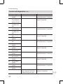
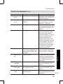
Troubleshooting
Control unit diagnostics .............................................................................. 123
Diagnosis ................................................................................................... 130
4
5592 969 GB
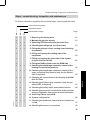
Commissioning, inspection, maintenance
Steps - commissioning, inspection and maintenance ................................... 99
Further details regarding the individual steps .............................................. 101
Index
5592 969 GB
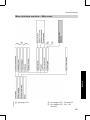
Index (cont.)
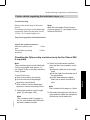
Control settings
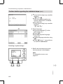
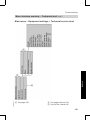
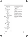
Menu structure overview – Main menu ........................................................
Menu structure overview – information ........................................................
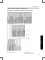
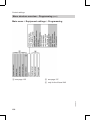
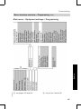
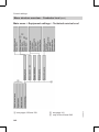
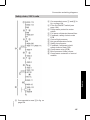
Menu structure overview – Programming.....................................................
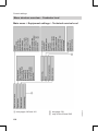
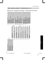
Menu structure overview – Contractor level .................................................
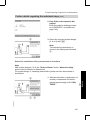
Control settings by contractors....................................................................
Activating the technical service level ...........................................................
Adjusting sensor temperatures....................................................................
Checking signal inputs ................................................................................
Manual control of relays and mixers ............................................................
133
134
135
138
142
142
143
144
144
Control unit settings – system definition
System design ............................................................................................
Power-OFF contact: 1S...............................................................................
Average time; outside temperature..............................................................
Heating limit < T room (heating limit temperature) ........................................
Temperature limit for reduced temperature mode.........................................
Frost protection temperature .......................................................................
147
147
147
148
148
149
Heat pump control settings
Power-OFF compressor ..............................................................................
Maximum flow temperature .........................................................................
Minimum return temperature .......................................................................
Hysteresis T primary/min. T primary in ........................................................
Minimum runtime ........................................................................................
Min. compressor off ....................................................................................
Flow; primary/secondary pump ...................................................................
Optimum runtime ........................................................................................
150
150
150
151
152
152
152
153
Electric heater control settings
E heating ....................................................................................................
Power-OFF; instantaneous heating water heater .........................................
Electric heating...........................................................................................
DHW with electric power .............................................................................
Maximum flow temperature .........................................................................
Heater rod delay .........................................................................................
Electric heating threshold ...........................................................................
Maximum stage; electric heater...................................................................
155
155
155
156
156
157
157
158
Internal hydraulics control settings
Heat pump for drying buildings .................................................................... 159
Time for drying buildings ............................................................................. 159
Flow hysteresis........................................................................................... 160
5
Index
Index (cont.)
Solar collector control settings (only for the Vitocal 242)
Solar collector ............................................................................................
Maximum temperature ................................................................................
Solar pump hysteresis ON/solar pump hysteresis OFF ................................
Pump kick hysteresis ..................................................................................
Pump kick runtime ......................................................................................
Pump kick dead time...................................................................................
Flow rate ....................................................................................................
162
162
162
163
164
165
165
DHW control settings
DHW cylinder temperature ..........................................................................
DHW program temperature .........................................................................
DHW circulation pump program...................................................................
Operating mode ..........................................................................................
DHW cylinder maximum..............................................................................
Hysteresis; DHW instantaneous heating water heater/hysteresis.................
Start optimisation........................................................................................
Stop optimisation ........................................................................................
DHW auxiliary function................................................................................
Set DHW temperature 2 ..............................................................................
Heat pump cylinder volume .........................................................................
Excess reaction ..........................................................................................
Maximum DHW runtime ..............................................................................
Maximum DHW interruption ........................................................................
166
166
166
166
167
167
169
169
169
169
169
170
170
170
Heating circuit control settings
Standard temperature .................................................................................
Reduced temperature .................................................................................
Temperature program, heating circuit ..........................................................
Remote control ...........................................................................................
Operating mode ..........................................................................................
Maximum flow temperature .........................................................................
Minimum flow temperature ..........................................................................
DHW during party mode ..............................................................................
Excess reaction ..........................................................................................
Room temperature sensor...........................................................................
Slope; room temperature hook-up ...............................................................
Room temperature hook-up ........................................................................
Start optimisation........................................................................................
Maximum flow temperature correction .........................................................
172
172
172
172
172
173
173
174
174
175
175
176
176
176
6
5592 969 GB
Internal pump run-on................................................................................... 160
Max. steps; three-way valve........................................................................ 160
Index
Index (cont.)
Room temperature control ..........................................................................
Adjusting the heating curve level and slope .................................................
Integral room temperature controller ...........................................................
Flow T excess .............................................................................................
Mixer runtime..............................................................................................
Mixer parameters........................................................................................
Screed function ..........................................................................................
Mixer active zone/dead zone.......................................................................
Natural cooling ...........................................................................................
Cooling limit > T room (cooling limit temperature) ........................................
Cooling curve level/slope ............................................................................
Natural cooling with mixer ...........................................................................
Active zone/dead zone natural cooling mixer...............................................
Cooling mixer runtime .................................................................................
Cooling mixer parameters ...........................................................................
177
178
178
178
179
179
180
181
182
183
183
184
185
185
186
Buffer cylinder control settings
Buffer cylinder ............................................................................................
Buffer cylinder program...............................................................................
Fixed temperature ......................................................................................
Hysteresis temperature...............................................................................
Maximum temperature ................................................................................
Stop optimisation ........................................................................................
Excess reaction ..........................................................................................
187
187
187
188
188
189
189
Components
Sensor resistance curves............................................................................ 191
Fuse ........................................................................................................... 192
5592 969 GB
Connection and wiring diagrams
Overview of the PCBs and connection options.............................................
Main connection area..................................................................................
Safety chain, 400 V units.............................................................................
Safety chain, 230 V units.............................................................................
Left part of the main PCB ............................................................................
Upper and lower part of the main PCB .........................................................
R.h. part of the main PCB............................................................................
193
194
196
197
198
200
202
Parts lists
Parts list Vitocal 242-G ............................................................................... 204
Parts list Vitocal 222-G ............................................................................... 210
7
Index
Index (cont.)
Commissioning/service reports
Hydraulic parameter report ......................................................................... 216
Control parameter report............................................................................. 217
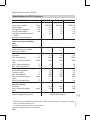
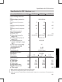
Specification for 400 V devices ................................................................ 222
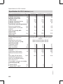
Specification for 230 V devices ................................................................ 226
Appendix
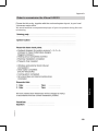
Order to commission the Vitocal 242/222 .................................................... 229
Certificates
Declaration of conformity ............................................................................ 230
Declaration of conformity ............................................................................ 231
5592 969 GB
Keyword index .......................................................................................... 232
8
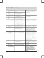
Preparing for installation
Transport
!
Please note
To avoid damage during transportation without the pallet,
never put weight onto the top,
front or side walls of the unit.
Never support the equipment
on its front or side panels.
Standard dimensions when tilted
Equipment on pal2 395 mm
let
Equipment alone
2 085 mm
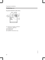
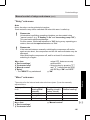
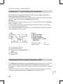
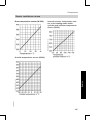
Positioning
Installation room requirements
Required room height when utilising
the connection panel: 2400 mm (min).
Note
To prevent damage to the building
structure, please pay attention to the
permissible load-bearing capacity of
the floor.
Type
5592 969 GB
BWT 106
BWT 108
BWT 110
Total weight incl. DHW
kg
520
530
535
The installation room must be dry and
safe from the risk of frost.
To prevent corrosion damage, provide
the brine-side heat pump installation
with thermal insulation in accordance
with current rules as vapour diffusion
proof installation.
To prevent structure-borne noise,
never set up the unit on wooden ceilings in the attic.
9
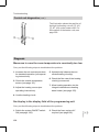
Installation
Please transport the unit in the crate
to protect it from damage. The crate
can be dismantled if the amount of
available space is limited.
Leave the pallet beneath the unit for
transportation.
We recommend you transport the
equipment on a Viessmann trolley.
Secure the unit with tension straps.
The max. permitted tilting angle for
the compressor during transportation
and installation is 30°.
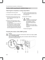
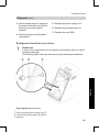
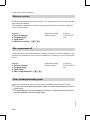
Preparing for installation
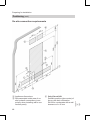
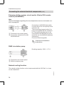
Positioning (cont.)
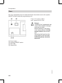
Top panel dimensions (plan view)
5592 969 GB
A Cable entry (length of cables in
unit approx. 1300 mm)
B Primary outlet
C Primary inlet
D Hydraulic connection array
10
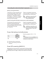
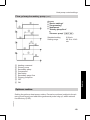
Preparing for installation
Positioning (cont.)
Installation
Clearance dimensions (plan view)
5592 969 GB
A min. 1000 mm
B Vitocal 242:
The required clearance for the
removal of the front panels is
20 mm. Also maintain this dimension when using decorative
frames.
Vitocal 222:
Maintain a clearance of 140 mm to
the left or right for the blow-off line
of the heating circuit safety valve.
C Optionally on the l.h. or r.h. side
D Vitocal 242: min. 15 mm (see
also page 57)
Vitocal 222: min. 45 mm (see
also page 59)
Maximum distance:
For distances > 80 mm fit the
power cables on site with strain
relief fittings.
11
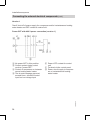
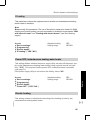
Preparing for installation
Positioning (cont.)
A Appliance dimensions
B Recommended outlet area of onsite hydraulic connections (compulsory when installing with a connection panel)
12
C Only Vitocal 242:
Possible position (pipe centre) of
the on-site drain connection
DN 32 for condensate with a wall
clearance of > 45 mm
5592 969 GB
On-site connection requirements
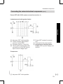
Preparing for installation
Positioning (cont.)
F Top edge – finished floor
G Only Vitocal 222:
Possible position (pipe centre) of
the on-site drain connection
DN 40 for the blow-off line of the
heating circuit safety valve.
Install a siphon on site
D Only Vitocal 242:
Position (centre pipe) of the onsite drain connection DN 32 for
condensate with a wall clearance
from 15 to 45 mm
E Possible exit area of brine-side
connections and/or on-site
cables.
Installation
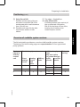
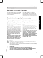
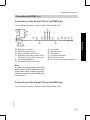
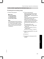
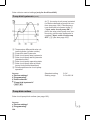
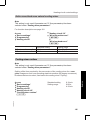
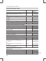
Overview of available system versions
The following table provides an overview of all possible system versions.
The designs on the following pages are representative for four typical heat
pump systems.
System
layout inside the
control
unit
2
Standard equipment
Direct
heating
circuit
Heating
circuit
with
mixer
X
DHW cylinder
X
Additional equip"Natural
ment
cooling"
(only one option
per system design)
Buffer
Low loss
cylinder header
X
X
X
4
6
X
X
X
X
X
X
X
X
X
5592 969 GB
X
13
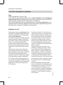
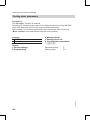
Preparing for installation
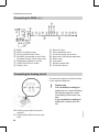
Function description of systems
Note
Never operate 230 V units in d.
A pre-requisite for operating 230 V units in some countries is that starting currents of up to 45 A are permissible in the power grid of the country concerned
(observe other country-specific regulations, if necessary).
The sample applications are recommendations and must be checked for completeness and functionality on site. Please observe the applicable regulations
and directives for design, installation and operation.
Heat pumps require a minimum heating water throughput. Ensure that the
values specified in the relevant datasheet are maintained.
Accurately calculated radiator heating
systems generally have a small system water content. With systems like
these, use a heating water buffer
cylinder with an appropriate capacity
to prevent the heat pump from being
switched on and off at frequent intervals.
Heat pumps can be shut off by the
power supply utility at peak load periods depending on the power tariff. For
this reason a heating water buffer
cylinder should be installed for rapidly
cooling heating systems (radiators).
The volume of the heating water buffer cylinder should be sufficient to prevent the stored heat from allowing the
building to cool down during powerOFF periods.
14
System versions 2 to 4 do not use a
secondary pump but a separate circulation pump as heating circuit pump.
We recommend the use of a heating
circuit pump with a slower flow rate
than the secondary pump. Install a
heating water buffer cylinder in parallel to the heating circuit to compensate for the difference between these
water volumes.
Systems with large volumes, e.g.
underfloor heating systems, will not
necessarily require a heating water
buffer cylinder. In these heating systems install an overflow valve at the
underfloor heating system heating circuit distributor that is furthest away
from the heat pump. This ensures that
the minimum water circulation volume
is provided, even in closed heating
circuits.
If an instantaneous heating water
heater is installed, a temperature limiter (accessory, order no. 7151 728 or
7151 729) must be installed in conjunction with an underfloor heating circuit. Install the temperature limiter, for
example, on the underfloor heating
circuit pump.
5592 969 GB
Heating circuit
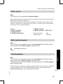
Preparing for installation
Function description of systems (cont.)
Heating water buffer cylinder operated in parallel
Bridging power-OFF periods
Constant flow rate through the heat
pump
& Longer heat pump operating times
Because of the increased water
volume of the heat source and the fact
that it may have a separate shut-off
facility, an additional (or larger)
expansion vessel should be provided.
Protect the heat pump with a fuse in
accordance with DIN 4751 [or local
regulations].
&
&
Systems without heating water buffer cylinder
Never install a mixer to safeguard the
minimum heating water circulation
volume.
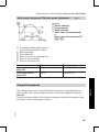
Natural cooling function
5592 969 GB
During the summer months the temperature level of the primary circuit
can be used to cool the building.
The natural cooling function is a
method of cooling buildings that
saves a considerable amount of
energy. All that is needed is a small
amount of electricity for the circulation
pumps to access the "cooling source"
in the ground.
During the cooling operation, the heat
pump will only be started to provide
DHW. The heat pump control system
actuates the circulation pumps, diverter valves and mixers and records the
temperature via the natural cooling
extension kit. Alternatively, this function can also be covered by on-site
components (for an on-site wiring
suggestion, see the Vitocal 200/222/
242 technical guide).
A contact humidistat monitors the dew
point.
The capability of the natural cooling
function cannot generally be compared with that of air-conditioning
equipment or water chillers. Natural
cooling provides no dehumidification.
15
Installation
Heating water buffer cylinders provide
a hydraulic separation of the flow in
the heat pump and heating circuits.
For example, the flow rate in the heat
pump circuit remains constant, even if
the heating circuit flow rate is reduced
by thermostatic valves.
The use of a heating water buffer
cylinder offers the following advantages:
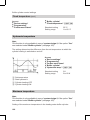
Preparing for installation
Function description of systems (cont.)
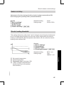
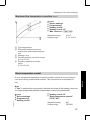
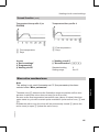
The cooling capacity depends on the
heat source temperature, which itself
is subject to seasonal fluctuations.
Experience has shown that the cooling capacity is higher at the beginning
of summer than at the end.
In addition, the water source temperature curve is subject to the cooling
demand of the building. Because of
large window areas or internal
sources (lighting, electrical equipment), the heat source temperature
increases more rapidly during the
course of a year than it does if less
cooling is required.
Underfloor heating systems and concrete core tempering are available for
cooling the building; radiator heating
systems are unsuitable for this purpose. Ensure that any installed room
thermostats are able to be opened
manually or by servomotors when
using the cooling function.
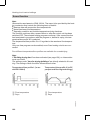
DHW heating with the heat pump
In the delivered condition, domestic
hot water heating by the heat pump is
given priority in the heating circuit and
should preferably take place overnight.
During cylinder heating, the control
unit switches the circulation pump
OFF to prevent the cylinder heating
from being impaired.
DHW heating with solar boost (only Vitocal 242)
During cylinder heating, the control
unit switches the circulation pump
OFF to prevent the cylinder heating
from being impaired.
5592 969 GB
If sufficient solar radiation is available, the DHW can be heated exclusively by the solar heating system.
To optimise the solar cover, heating
the DHW cylinder by heat pump
should be limited to the upper cylinder
volume. This is achieved via an integral, manually activated three-way
diverter valve.
16
Preparing for installation
Function description of systems (cont.)
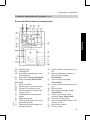
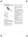
5592 969 GB
Installation
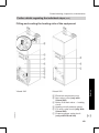
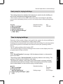
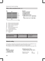
Overview of the internal components
HR Heating return
HV Heating flow
KW Cold water (connections, see
from page 94)
RL Solar return (only Vitocal 242)
VL Solar flow (only Vitocal 242)
WW DHW
Z
DHW circulation
A Primary return (primary outlet)
B Primary flow (primary inlet)
C Flow temperature sensor; secondary circuit
D Instantaneous heating water
heater
E Secondary pump
F Three-way diverter valve "Central heating/DHW"
G Plate-type heat exchanger for
cylinder heating
H
K
L
M
N
O
P
R
S
T
U
Upper cylinder temperature sensor
Return temperature sensor of
the solar circuit (only
Vitocal 242)
Solar circuit pump (only
Vitocal 242)
Lower cylinder temperature sensor
DHW cylinder
Solar heat exchanger (only
Vitocal 242)
Three-way diverter valve
(manual) (only Vitocal 242)
Cylinder primary pump
Return temperature sensor; secondary circuit
Heat pump module
Primary pump
17
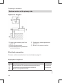
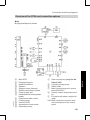
Preparing for installation
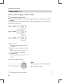
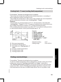
System version on the primary side
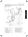
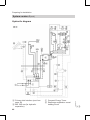
Hydraulic diagram
A Heat pump interface (see from
page 19)
2 Brine accessory pack
3 Brine distributor for geothermal
probes/collectors
4 Geothermal probes/geothermal
collectors
qQ Brine circuit pressure switch
Electrical connection
Pressure switch connection for brine circuit, qQ see page 21.
Equipment required
Description
Brine accessory pack
Brine distributor for geothermal probes/collectors
Geothermal probes/geothermal collectors
Brine circuit pressure switch
Number
1
as required
as required
1
5592 969 GB
Pos.
2
3
4
qQ
18
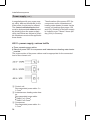
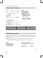
Preparing for installation
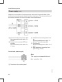
System version 1
One directly connected heating circuit, DHW heating with solar boost
(option) and natural cooling function (option)
Note
Solar boosted DHW heating is only possible with the Vitocal 242.
To achieve this system version, select system design 2 at the control unit.
5592 969 GB
Installation
Hydraulic diagram
19
Preparing for installation
System version 1 (cont.)
wI
wO
eP
eQ
eW
eE
eR
eT
rQ
rW
wE
wR
wT
wZ
Heating circuit extension
Connection panel
Contact humidistat
Circulation pump (secondary
cooling circuit pump)
Three-way diverter valve heating/
cooling
2-way motorised ball valve
Frost stat
Circulation pump (primary cooling
circuit pump)
Cooling circuit flow temperature
sensor
Cooling circuit mixer motor
Only in conjunction with
Vitocal 242:
Solar collector
Collector temperature sensor
Diaphragm expansion vessel,
solar circuit
Solar circuit extension
5592 969 GB
A Primary side interface (see from
page 18)
B Min. 500 mm (for hydraulic
separation)
1 Compact Energy Tower
5 Overflow valve
6 Diaphragm expansion vessel
heating circuit
7 Temperature limiter underfloor
heating circuit (connection see
page 68)
8 Plate-type heat exchanger
qP Underfloor heating circuit
qE DHW circulation pump
qR Natural cooling extension kit
qU KM BUS distributor
qI Vitotrol 200 remote control
qO Room temperature sensor
wP Extension kit for cooling circuit
with mixer
wQ Outside temperature sensor
wU DHW circulation extension
20
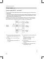
Preparing for installation
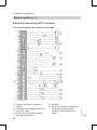
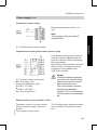
System version 1 (cont.)
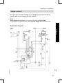
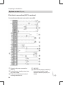
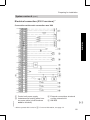
Electrical connection (400 V versions)
5592 969 GB
Installation
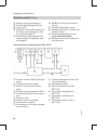
Connections at the main connection area X60
F Control unit power connection
(230 V)
G Instantaneous heating water heater power cable
H External connections at natural
cooling extension kit
K KM BUS
qQ Brine circuit pressure switch (if
the pressure switch is not
installed, use the jumper provided)
qE DHW circulation pump
21
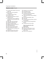
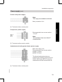
Preparing for installation
System version 1 (cont.)
qR
qT
qZ
qI
Natural cooling extension kit
Central fault message (230 V)
Power-OFF
KM BUS: Vitotrol 200 remote control (with room temperature sensor), see also page 67
qO Room temperature sensor (if no
remote control is installed), see
also page 67
wP KM BUS: Cooling circuit extension kit
wQ Outside temperature sensor
wR Collector temperature sensor
(only with Vitocal 242)
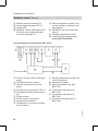
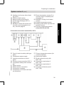
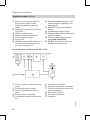
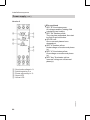
Connections to control module X80, 400 V
L Primary temperature sensor (for
control purposes)
M Heat pump module
N Direct connection only with
BWT 106
O Connection required as of
BWT 108
P Connection required as of
BWT 108
R Full wave soft starter (as of
BWT 108)
5592 969 GB
A Front of control module (with type
plate)
B Compressor power supply
C Internal connection to control
panel
D Primary pump connection (230 V)
E Compressor safety chain connection
F Phase monitor
G Phase monitor connection
H Compressor contactor
K Compressor or full wave soft starter connection
22
Preparing for installation
System version 1 (cont.)
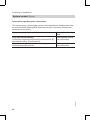
Information regarding other connections
The primary pump, the secondary pump, the instantaneous heating water heater and the central heating/DHW three-way diverter valve have already been
connected in the factory.
see page 68
5592 969 GB
Only with natural cooling:
Connect the required components to extension kit wP
and natural cooling qR extension kit
Only when using an underfloor heating system:
Connect temperature limiter
Connection description
See separate installation instructions
Installation
Components to be connected
23
Preparing for installation
System version 1 (cont.)
Electrical connection (230 V versions) * 1
Connections at the main connection area X60
*1 Never
24
H External connections at natural
cooling extension kit
K KM BUS
operate 230 V units in d. For more information, see page 14.
5592 969 GB
F Control unit power supply
G Instantaneous heating water heater power cable (circuit breakers
must be blocked)
Preparing for installation
System version 1 (cont.)
qO Room temperature sensor (if no
remote control is installed), see
also page 67
wP KM BUS: Cooling circuit extension kit
wQ Outside temperature sensor
wR Collector temperature sensor
(only with Vitocal 242)
Installation
qQ Brine circuit pressure switch (if
the pressure switch is not
installed, use the jumper provided)
qE DHW circulation pump
qR Natural cooling extension kit
qT Central fault message
qZ Power-OFF
qI KM BUS: Vitotrol 200 remote control (with room temperature sensor), see also page 67
Connections to control module X80, 230 V
A Front of control module (with type
plate)
B Compressor power supply
C Internal connection to control
panel
D Primary pump connection
E Compressor safety chain connection
H Compressor contactor
K Full wave soft starter connection
L Primary temperature sensor (for
control purposes)
M Heat pump module
R Full wave soft starter
S Capacitor
5592 969 GB
Information regarding other connections
The primary pump, the secondary pump, the instantaneous heating water heater and the central heating/DHW three-way diverter valve have already been
connected in the factory.
25
Preparing for installation
System version 1 (cont.)
Components to be connected
Connect capacitor to full wave soft starter
Only with natural cooling:
Connect the required components to extension kit wP
and natural cooling qR extension kit
Only when using an underfloor heating system:
Connect temperature limiter
Connection description
see page 89
See separate installation instructions
see page 68
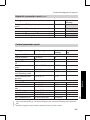
Equipment required for system version 1
26
Number
1
1
1
1
1
1
1
1
1
1
1
1
as required
1
1
1
1
1
1
1
1
1
1
1
1
5592 969 GB
Equipment required
Pos. Description
1
Compact Energy Tower
5
Overflow valve
6
Diaphragm expansion vessel for the heating circuit
7
Temperature limiter (only required for the underfloor heating circuit)
qP
Underfloor heating circuit
qU
KM BUS distributor
qI
Vitotrol 200 remote control
qO
Room temperature sensor
wI
Heating circuit extension
wO
Connection panel
DHW circulation option
qE
DHW circulation pump
wU
DHW circulation extension
Option solar heating circuit (only with Vitocal 242)
wE
Solar collectors
wR
Collector temperature sensor
wT
Diaphragm expansion vessel for the solar circuit
wZ
Solar circuit extension
Option "Natural cooling" function
8
Vitotrans 100, plate-type heat exchanger
qR
Natural cooling extension kit
wP
Extension kit for cooling circuit with mixer
eP
Natural cooling contact humidistat
eQ
Circulation pump (secondary cooling circuit pump)
eW
Three-way diverter valve heating/cooling
eE
Motorised two-way ball valve (for the brine circuit)
eR
Frost stat
eT
Circulation pump (primary cooling circuit pump)
Preparing for installation
System version 1 (cont.)
Pos.
rQ
rW
Description
Cooling circuit flow temperature sensor
Cooling circuit mixer motor
Number
1
1
One directly connected heating circuit with heating water buffer cylinder,
DHW heating with solar boost (option) and natural cooling function
(option)
5592 969 GB
Note
Solar boosted DHW heating is only possible with the Vitocal 242.
To achieve this system version, select system design 2 at the control unit.
27
Installation
System version 2
Preparing for installation
System version 2 (cont.)
A Primary side interface (see from
page 18)
B Min. 500 mm (for hydraulic
separation)
1 Compact Energy Tower
6 Diaphragm expansion vessel
heating circuit
7 Underfloor heating circuit temperature limiter
28
8
9
qP
qW
qE
qR
qU
qI
Plate-type heat exchanger
Heating water buffer cylinder
Underfloor heating circuit
Heating circuit pump, direct heating circuit
DHW circulation pump
Natural cooling extension kit
KM BUS distributor
Vitotrol 200 remote control
5592 969 GB
Hydraulic diagram
Preparing for installation
System version 2 (cont.)
eT Circulation pump (primary cooling
circuit pump)
rQ Cooling circuit flow temperature
sensor
rW Cooling circuit mixer motor
wZ
Installation
wE
wR
wT
Only in conjunction with
Vitocal 242:
Solar collector
Collector temperature sensor
Diaphragm expansion vessel,
solar circuit
Solar circuit extension
5592 969 GB
qO Room temperature sensor
wP Extension kit for cooling circuit
with mixer
wQ Outside temperature sensor
wW Heating water buffer cylinder temperature sensor
wU DHW circulation extension
wI Heating circuit extension
wO Connection panel
eP Contact humidistat
eW Three-way diverter valve heating/
cooling
eE 2-way motorised ball valve
eR Frost stat
29
Preparing for installation
System version 2 (cont.)
Electrical connection (400 V versions)
F Control unit power connection
(230 V)
G Instantaneous heating water heater power cable
H External connections at natural
cooling extension kit
30
K KM BUS
qQ Brine circuit pressure switch (if
the pressure switch is not
installed, use the jumper provided)
5592 969 GB
Connections at the main connection area X60
Preparing for installation
System version 2 (cont.)
qO Room temperature sensor (if no
remote control is installed), see
also page 67
wP KM BUS: Cooling circuit extension kit
wQ Outside temperature sensor
wW Heating water buffer cylinder temperature sensor
wR Collector temperature sensor
(only with Vitocal 242)
Installation
qW Heating circuit pump, direct heating circuit
qE DHW circulation pump
qR Natural cooling extension kit
qT Central fault message (230 V)
qZ Power-OFF
qI KM BUS: Vitotrol 200 remote control (with room temperature sensor), see also page 67
Connections to control module X80, 400 V
L Primary temperature sensor (for
control purposes)
M Heat pump module
N Direct connection only with
BWT 106
O Connection required as of
BWT 108
P Connection required as of
BWT 108
R Full wave soft starter (as of
BWT 108)
5592 969 GB
A Front of control module (with type
plate)
B Compressor power supply
C Internal connection to control
panel
D Primary pump connection (230 V)
E Compressor safety chain connection
F Phase monitor
G Phase monitor connection
H Compressor contactor
K Compressor or full wave soft starter connection
31
Preparing for installation
System version 2 (cont.)
Information regarding other connections
The primary pump, the secondary pump, the instantaneous heating water heater and the central heating/DHW three-way diverter valve have already been
connected in the factory.
Components to be connected
See separate installation instructions
5592 969 GB
Only with natural cooling:
Connect the required components to extension kit wP
and natural cooling qR extension kit
Only when using an underfloor heating system:
Connect temperature limiter
Connection description
See separate installation instructions
32
Preparing for installation
System version 2 (cont.)
Electrical connection (230 V versions) * 1
5592 969 GB
Installation
Connections at the main connection area X60
F Control unit power supply
G Instantaneous heating water heater power cable (circuit breakers
must be blocked)
*1 Never
H External connections at natural
cooling extension kit
K KM BUS
operate 230 V units in d. For more information, see page 14.
33
Preparing for installation
System version 2 (cont.)
qQ Brine circuit pressure switch (if
the pressure switch is not
installed, use the jumper provided)
qW Heating circuit pump, direct heating circuit
qE DHW circulation pump
qR Natural cooling extension kit
qT Central fault message
qZ Power-OFF
qI KM BUS: Vitotrol 200 remote control (with room temperature sensor), see also page 67
qO Room temperature sensor (if no
remote control is installed), see
also page 67
wP KM BUS: Cooling circuit extension kit
wQ Outside temperature sensor
wW Heating water buffer cylinder temperature sensor
wR Collector temperature sensor
(only with Vitocal 242)
Connections to control module X80, 230 V
H Compressor contactor
K Full wave soft starter connection
L Primary temperature sensor (for
control purposes)
M Heat pump module
R Full wave soft starter
S Capacitor
5592 969 GB
A Front of control module (with type
plate)
B Compressor power supply
C Internal connection to control
panel
D Primary pump connection
E Compressor safety chain connection
34
Preparing for installation
System version 2 (cont.)
Information regarding other connections
Components to be connected
Connect capacitor to full wave soft starter
Only with natural cooling:
Connect the required components to extension kit wP
and natural cooling qR extension kit
Only when using an underfloor heating system:
Connect temperature limiter
Connection description
see page 89
See separate installation instructions
See separate installation instructions
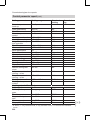
Equipment required for system version 2
Pos.
1
6
7
9
qP
qW
qU
qI
qO
wW
wI
wO
5592 969 GB
qE
wU
wE
wR
wT
wZ
8
Description
Compact Energy Tower
Diaphragm expansion vessel for the heating circuit
Temperature limiter (only required for the underfloor heating circuit)
Heating water buffer cylinder
Underfloor heating circuit
Heating circuit pump, direct heating circuit
KM BUS distributor
Vitotrol 200 remote control
Room temperature sensor
Cylinder temperature sensor for capturing the temperature inside the heating water buffer cylinder (top)
Heating circuit extension
Connection panel
DHW circulation option
DHW circulation pump
DHW circulation extension
Option solar heating circuit (only with Vitocal 242)
Solar collectors
Collector temperature sensor
Diaphragm expansion vessel for the solar circuit
Solar circuit extension
Option "Natural cooling" function
Vitotrans 100, plate-type heat exchanger
Number
1
1
1
1
1
1
1
1
1
1
1
1
1
1
as required
1
1
1
35
Installation
The primary pump, the secondary pump, the instantaneous heating water heater and the central heating/DHW three-way diverter valve have already been
connected in the factory.
Preparing for installation
System version 2 (cont.)
Pos.
qR
wP
eP
eW
eE
eR
eT
rQ
rW
Description
Natural cooling extension kit
Extension kit for cooling circuit with mixer
Natural cooling contact humidistat
Three-way diverter valve heating/cooling
Motorised two-way ball valve (for the brine circuit)
Frost stat
Circulation pump (primary cooling circuit pump)
Cooling circuit flow temperature sensor
Cooling circuit mixer motor
Number
1
1
1
1
1
1
1
1
1
System version 3
One mixer circuit with heating water buffer cylinder, DHW heating with
solar boost (option) and natural cooling function (option)
5592 969 GB
Note
Solar boosted DHW heating is only possible with the Vitocal 242.
To achieve this system version, select system design 4 at the control unit.
36
Preparing for installation
System version 3 (cont.)
5592 969 GB
Installation
Hydraulic diagram
A Primary side interface (see from
page 18)
B Min. 500 mm (for hydraulic
separation)
1 Compact Energy Tower
6 Diaphragm expansion vessel
heating circuit
7 Underfloor heating circuit temperature limiter
8
9
qP
qE
qR
qU
qI
qO
Plate-type heat exchanger
Heating water buffer cylinder
Underfloor heating circuit
DHW circulation pump
Natural cooling extension kit
KM BUS distributor
Vitotrol 200 remote control
Room temperature sensor
37
Preparing for installation
System version 3 (cont.)
rP Heating circuit pump, mixer circuit
rQ Flow temperature sensor, mixer
circuit
rW Three-way mixer - mixer motor
tP Extension kit for one heating circuit with mixer
wE
wR
wT
wZ
Only in conjunction with
Vitocal 242:
Solar collector
Collector temperature sensor
Diaphragm expansion vessel,
solar circuit
Solar circuit extension
5592 969 GB
wP Extension kit for cooling circuit
with mixer
wQ Outside temperature sensor
wW Heating water buffer cylinder temperature sensor
wU DHW circulation extension
wI Heating circuit extension
wO Connection panel
eP Contact humidistat
eW Three-way diverter valve heating/
cooling
eE 2-way motorised ball valve
eR Frost stat
eT Circulation pump (primary cooling
circuit pump)
38
Preparing for installation
System version 3 (cont.)
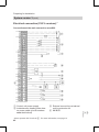
Electrical connection (400 V versions)
5592 969 GB
Installation
Connections at the main connection area X60
F Control unit power connection
(230 V)
G Instantaneous heating water heater power cable
H External connections at natural
cooling extension kit
K KM BUS
qQ Brine circuit pressure switch (if
the pressure switch is not
installed, use the jumper provided)
qE DHW circulation pump
39
Preparing for installation
System version 3 (cont.)
qR
qT
qZ
qI
Natural cooling extension kit
Central fault message (230 V)
Power-OFF
KM BUS: Vitotrol 200 remote control (with room temperature sensor), see also page 67
qO Room temperature sensor (if no
remote control is installed), see
also page 67
wP KM BUS: Cooling circuit extension kit
wQ Outside temperature sensor
wW Heating water buffer cylinder temperature sensor
wR Collector temperature sensor
(only with Vitocal 242)
tP Extension kit for one heating circuit with mixer
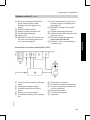
Connections to control module X80, 400 V
L Primary temperature sensor (for
control purposes)
M Heat pump module
N Direct connection only with
BWT 106
O Connection required as of
BWT 108
P Connection required as of
BWT 108
R Full wave soft starter (as of
BWT 108)
5592 969 GB
A Front of control module (with type
plate)
B Compressor power supply
C Internal connection to control
panel
D Primary pump connection (230 V)
E Compressor safety chain connection
F Phase monitor
G Phase monitor connection
H Compressor contactor
K Compressor or full wave soft starter connection
40
Preparing for installation
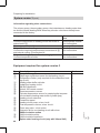
System version 3 (cont.)
Information regarding other connections
Components to be connected
See separate installation instructions
5592 969 GB
Connect components for heating circuit with mixer to
extension kit tP
Only with natural cooling:
Connect the required components to extension kit wP
and natural cooling qR extension kit
Only when using an underfloor heating system:
Connect temperature limiter
Connection description
See separate installation instructions
See separate installation instructions
41
Installation
The primary pump, the secondary pump, the instantaneous heating water heater and the central heating/DHW three-way diverter valve have already been
connected in the factory.
Preparing for installation
System version 3 (cont.)
Electrical connection (230 V versions) * 1
Connections at the main connection area X60
*1 Never
42
H External connections at natural
cooling extension kit
K KM BUS
operate 230 V units in d. For more information, see page 14.
5592 969 GB
F Control unit power supply
G Instantaneous heating water heater power cable (circuit breakers
must be blocked)
Preparing for installation
qQ Brine circuit pressure switch (if
the pressure switch is not
installed, use the jumper provided)
qE DHW circulation pump
qR Natural cooling extension kit
qT Central fault message
qZ Power-OFF
qI KM BUS: Vitotrol 200 remote control (with room temperature sensor), see also page 67
qO Room temperature sensor (if no
remote control is installed), see
also page 67
wP KM BUS: Cooling circuit extension kit
wQ Outside temperature sensor
wW Heating water buffer cylinder temperature sensor
wR Collector temperature sensor
(only with Vitocal 242)
tP Extension kit for one heating circuit with mixer
Connections to control module X80, 230 V
H Compressor contactor
K Full wave soft starter connection
L Primary temperature sensor (for
control purposes)
M Heat pump module
R Full wave soft starter
S Capacitor
5592 969 GB
A Front of control module (with type
plate)
B Compressor power supply
C Internal connection to control
panel
D Primary pump connection
E Compressor safety chain connection
43
Installation
System version 3 (cont.)
Preparing for installation
System version 3 (cont.)
Information regarding other connections
The primary pump, the secondary pump, the instantaneous heating water heater and the central heating/DHW three-way diverter valve have already been
connected in the factory.
Components to be connected
Connect components for heating circuit with mixer to
extension kit tP
Connect capacitor to full wave soft starter
Only with natural cooling:
Connect the required components to extension kit wP
and natural cooling qR extension kit
Only when using an underfloor heating system:
Connect temperature limiter
Connection description
See separate installation instructions
see page 89
See separate installation instructions
See separate installation instructions
Equipment required for system version 3
9
qP
qU
qI
qO
wW
wI
wO
rP
rQ
rW
tP
qE
wU
44
Description
Compact Energy Tower
Diaphragm expansion vessel for the heating circuit
Temperature limiter (only required for the underfloor heating circuit)
Heating water buffer cylinder
Underfloor heating circuit
KM BUS distributor
Vitotrol 200 remote control
Room temperature sensor
Cylinder temperature sensor for capturing the temperature inside the heating water buffer cylinder (top)
Heating circuit extension
Connection panel
Heating circuit pump, mixer circuit
Flow temperature sensor, mixer circuit
Three-way mixer - mixer motor
Extension kit for one heating circuit with mixer
DHW circulation option
DHW circulation pump
DHW circulation extension
Option solar heating circuit (only with Vitocal 242)
Number
1
1
1
1
1
1
1
1
1
1
1
1
1
1
1
1
5592 969 GB
Pos.
1
6
7
Preparing for installation
System version 3 (cont.)
8
qR
wP
eP
eW
eE
eR
eT
rQ
rW
Description
Solar collectors
Collector temperature sensor
Diaphragm expansion vessel for the solar circuit
Solar circuit extension
Option "Natural cooling" function
Vitotrans 100, plate-type heat exchanger
Natural cooling extension kit
Extension kit for cooling circuit with mixer
Natural cooling contact humidistat
3-way diverter valve
Motorised two-way ball valve (for the brine circuit)
Frost stat
Circulation pump (primary cooling circuit pump)
Flow temperature sensor, mixer circuit
Three-way mixer - mixer motor
Number
as required
1
1
1
1
1
1
1
1
1
1
1
1
Installation
Pos.
wE
wR
wT
wZ
System version 4
One directly connected heating circuit, one mixer circuit, heating water
buffer cylinder, DHW heating with solar boost (option) and natural cooling
function (option)
5592 969 GB
Note
Solar boosted DHW heating is only possible with the Vitocal 242.
To achieve this system version, select system design 6 at the control unit.
45
Preparing for installation
System version 4 (cont.)
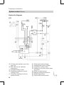
A Primary side interface (see from
page 18)
B Min. 500 mm (for hydraulic
separation)
46
1 Compact Energy Tower
6 Diaphragm expansion vessel
heating circuit
5592 969 GB
Hydraulic diagram
Preparing for installation
eW Three-way diverter valve heating/
cooling
eE 2-way motorised ball valve
eR Frost stat
eT Circulation pump (primary cooling
circuit pump)
rP Heating circuit pump, mixer circuit
rQ Flow temperature sensor, mixer
circuit
rW Three-way mixer - mixer motor
tP Extension kit for one heating circuit with mixer
zP Radiator heating circuit
wE
wR
wT
wZ
Only in conjunction with
Vitocal 242:
Solar collector
Collector temperature sensor
Diaphragm expansion vessel,
solar circuit
Solar circuit extension
5592 969 GB
7 Underfloor heating circuit temperature limiter
8 Plate-type heat exchanger
9 Heating water buffer cylinder
qP Underfloor heating circuit
qW Heating circuit pump, direct heating circuit
qE DHW circulation pump
qR Natural cooling extension kit
qU KM BUS distributor
qI Vitotrol 200 remote control
qO Room temperature sensor
wP Extension kit for cooling circuit
with mixer
wQ Outside temperature sensor
wW Heating water buffer cylinder temperature sensor
wU DHW circulation extension
wI Heating circuit extension
wO Connection panel
eP Contact humidistat
47
Installation
System version 4 (cont.)
Preparing for installation
System version 4 (cont.)
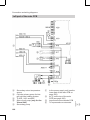
Electrical connection (400 V versions)
F Control unit power connection
(230 V)
G Instantaneous heating water heater power cable
H External connections at natural
cooling extension kit
48
K KM BUS
qQ Brine circuit pressure switch (if
the pressure switch is not
installed, use the jumper provided)
5592 969 GB
Connections at the main connection area X60
Preparing for installation
System version 4 (cont.)
wP KM BUS: Cooling circuit extension kit
wQ Outside temperature sensor
wW Heating water buffer cylinder temperature sensor
wR Collector temperature sensor
(only with Vitocal 242)
tP KM BUS: Extension kit for one
heating circuit with mixer
Installation
qW Heating circuit pump, direct heating circuit
qE DHW circulation pump
qR Natural cooling extension kit
qT Central fault message (230 V)
qZ Power-OFF
qI KM BUS: Vitotrol 200 remote control (with room temperature sensor), see also page 67
qO Room temperature sensor (if no
remote control is installed), see
also page 67
5592 969 GB
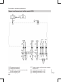
Connections to control module X80, 400 V
A Front of control module (with type
plate)
B Compressor power supply
C Internal connection to control
panel
D Primary pump connection (230 V)
E Compressor safety chain connection
F Phase monitor
G Phase monitor connection
H Compressor contactor
K Compressor or full wave soft starter connection
L Primary temperature sensor (for
control purposes)
M Heat pump module
N Direct connection only with
BWT 106
O Connection required as of
BWT 108
P Connection required as of
BWT 108
R Full wave soft starter (as of
BWT 108)
49
Preparing for installation
System version 4 (cont.)
Information regarding other connections
The primary pump, the secondary pump, the instantaneous heating water heater and the central heating/DHW three-way diverter valve have already been
connected in the factory.
Components to be connected
See separate installation instructions
5592 969 GB
Connect components for heating circuit with mixer to
extension kit tP
Only with natural cooling:
Connect the required components to extension kit wP
and natural cooling qR extension kit
Only when using an underfloor heating system:
Connect temperature limiter
Connection description
See separate installation instructions
See separate installation instructions
50
Preparing for installation
System version 4 (cont.)
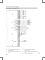
Electrical connection (230 V versions) * 1
5592 969 GB
Installation
Connections at the main connection area X60
F Control unit power supply
G Instantaneous heating water heater power cable (circuit breakers
must be blocked)
*1 Never
H External connections at natural
cooling extension kit
K KM BUS
operate 230 V units in d. For more information, see page 14.
51
Preparing for installation
System version 4 (cont.)
qQ Brine circuit pressure switch (if
the pressure switch is not
installed, use the jumper provided)
qW Heating circuit pump, direct heating circuit
qE DHW circulation pump
qR Natural cooling extension kit
qT Central fault message
qZ Power-OFF
qI KM BUS: Vitotrol 200 remote control (with room temperature sensor), see also page 67
qO Room temperature sensor (if no
remote control is installed), see
also page 67
wP KM BUS: Cooling circuit extension kit
wQ Outside temperature sensor
wW Heating water buffer cylinder temperature sensor
wR Collector temperature sensor
(only with Vitocal 242)
tP KM BUS: Extension kit for one
heating circuit with mixer
Connections to control module X80, 230 V
H Compressor contactor
K Full wave soft starter connection
L Primary temperature sensor (for
control purposes)
M Heat pump module
R Full wave soft starter
S Capacitor
5592 969 GB
A Front of control module (with type
plate)
B Compressor power supply
C Internal connection to control
panel
D Primary pump connection
E Compressor safety chain connection
52
Preparing for installation
System version 4 (cont.)
Information regarding other connections
Components to be connected
Connect components for heating circuit with mixer to
extension kit tP
Connect capacitor to full wave soft starter
Only with natural cooling:
Connect the required components to extension kit wP
and natural cooling qR extension kit
Only when using an underfloor heating system:
Connect temperature limiter
Connection description
See separate installation instructions
see page 89
See separate installation instructions
See separate installation instructions
Equipment required for system version 4
Pos.
1
6
7
5592 969 GB
9
qP
qW
qU
qI
qO
wW
wI
wO
rP
rQ
rW
tP
zP
qE
Description
Compact Energy Tower
Diaphragm expansion vessel for the heating circuit
Temperature limiter (only required for the underfloor heating circuit)
Heating water buffer cylinder
Underfloor heating circuit
Heating circuit pump, direct heating circuit
KM BUS distributor
Vitotrol 200 remote control
Room temperature sensor
Cylinder temperature sensor for capturing the temperature inside the heating water buffer cylinder (top)
Heating circuit extension
Connection panel
Heating circuit pump, mixer circuit
Flow temperature sensor, mixer circuit
Three-way mixer - mixer motor
Extension kit for one heating circuit with mixer
Radiator heating circuit
DHW circulation option
DHW circulation pump
Number
1
1
1
1
1
1
1
2
2
1
1
1
1
1
1
1
1
1
53
Installation
The primary pump, the secondary pump, the instantaneous heating water heater and the central heating/DHW three-way diverter valve have already been
connected in the factory.
Preparing for installation
System version 4 (cont.)
Pos.
wU
wE
wR
wT
wZ
Number
1
as required
1
1
1
1
1
1
1
1
1
1
1
1
1
5592 969 GB
8
qR
wP
eP
eW
eE
eR
eT
rQ
rW
Description
DHW circulation extension
Option solar heating circuit (only with Vitocal 242)
Solar collectors
Collector temperature sensor
Diaphragm expansion vessel for the solar circuit
Solar circuit extension
Option "Natural cooling" function
Vitotrans 100, plate-type heat exchanger
Natural cooling extension kit
Extension kit for cooling circuit with mixer
Natural cooling contact humidistat
Three-way diverter valve heating/cooling
Motorised two-way ball valve (for the brine circuit)
Frost stat
Circulation pump (primary cooling circuit pump)
Flow temperature sensor, mixer circuit
Three-way mixer - mixer motor
54
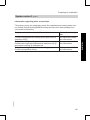
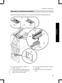
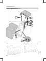
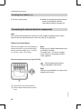
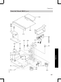
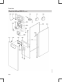
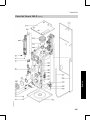
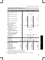
Installation sequence
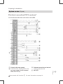
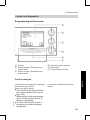
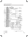
Summary of electrical connections
5592 969 GB
Installation
The following table provides an overview of all electrical connecting areas.
A Full wave soft starter, 400 V or
230 V version
B Junction box with X60 main connecting area and X50 additional
internal connecting area
C Control module with X80 connecting area
D Main PCB with X16 connecting
area
55
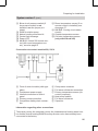
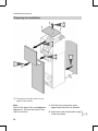
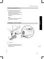
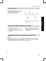
Installation sequence
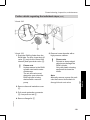
Preparing the installation
A Clearance from the wall or front
edge of the recess.
56
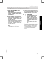
1. Pull the front panel at its upper
edge forward and lift out upwards.
2. Undo the screw at the bottom edge
of the front panel.
5592 969 GB
Note
Position the back of the unit temporarily approx. 500 mm from the on-site
drain connection.
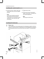
Installation sequence
Preparing the installation (cont.)
3. Pull the upper front panel at its
lower edge forward and lift out
upwards.
4. Release the front top panel.
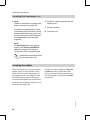
Installation
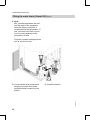
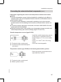
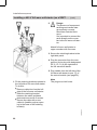
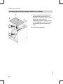
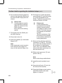
Fitting the water drain (Vitocal 242)
Note
To prevent damage to the connecting
cables with wall clearances of > 80
mm, the connecting cables must be
provided with strain relief on site.
1. Release the siphon.
3. Note
Check the drain connection for
leaks before settling the equipment in its final position and filling
the DHW cylinder.
Connect the drain hose with the onsite drain connection DN 32.
5592 969 GB
2. Release the drain hose from the
siphon and stretch (pull forward out
of the equipment).
57
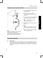
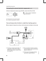
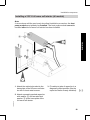
Installation sequence
Fitting the water drain (Vitocal 242) (cont.)
4. Note
Min. clearance between the wall
and the back of the equipment
when the drain connection is
located behind the equipment: 15
mm, and when the drain connection is located adjacent to the
equipment: 45 mm.
Push the compact unit against the
wall or into the recess.
6. Install the siphon.
5592 969 GB
5. Compress the drain hose that is
hanging out of the front of the
equipment and connect it to the
siphon.
58
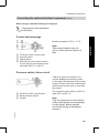
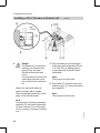
Installation sequence
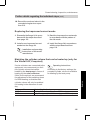
Fitting the water drain (Vitocal 222)
1. Fit the threaded ferrule at the back
of the equipment
2. Push the drain hose onto the
threaded ferrule and secure with a
hose clip.
Installation instructions;
drain outlet kit
4. Push the drain hose into the drain
outlet kit.
5. Note
Min. clearance between the wall
and the back of the device 45 mm.
Note
To prevent damage to the connecting
cables with wall clearances of
> 80 mm, the connecting cables must
be provided with strain relief on site.
Push the compact unit against the
wall or into the recess.
Heat pump preparation
Please note
If the compressor is at a steep angle in the heat pump module, the introduction of lubricant into the refrigerant circuit will damage the equipment.
The heat pump module must not be tilted by more than 30° during transportation.
5592 969 GB
!
59
Installation
3. Connect the drain outlet kit with the
on-site drain connection DN 40.
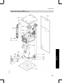
Installation sequence
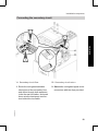
Heat pump preparation (cont.)
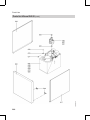
2. Remove the top part of the thermal
insulation.
3. Insert the strain relief with inserted
cables (lying at the bottom of the
thermal insulation) into the groove
of the recess in the lower part of
the thermal insulation.
60
4. Check the floor area, valves and all
visible solder joints of the heat
pump for traces of oil.
Note
Traces of oil indicate a leaking
refrigerant circuit. Ask a refrigeration engineer to check the heat
pump.
5592 969 GB
1. Remove the front part of the thermal insulation.
Installation sequence
Heat pump preparation (cont.)
5. Lead the thermal insulation A of
the primary inlets and outlets
through the openings in the top part
of the thermal insulation B.
Position the top part of the thermal
insulation.
Installation
Note
Do not push the thermal insulation
together when doing this.
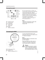
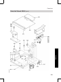
Installing the control module
A Type plate
5592 969 GB
1. Undo 2 pre-installed screws on the
underside of the control panel, but
do not unscrew.
61
Installation sequence
Installing the control module (cont.)
2. Suspend control module (with type
plate at the front) over the undone
screws.
Note
If the control module cannot be
fitted without touching internal
components, the 2 screws must be
relocated in one of the two additional holes.
3. Tighten the screws.
4. Fit the control panel connecting
cable (7-pin) to pos. C at the control unit (see page 22).
Note
The plug must click home.
Inserting the heat pump
Please note
If the compressor is at a steep angle in the heat pump module, the introduction of lubricant into the refrigerant circuit will damage the equipment.
The heat pump module must not be tilted more than 30° during installation.
5592 969 GB
!
62
Installation sequence
Inserting the heat pump (cont.)
1. Remove the control panel and put it
on top of the heat exchanger.
3. Lift the edge protector and remove
the l.h. retaining panel with special
stud.
Installation
2. Remove the crossbar.
5592 969 GB
4. Note
Position the heat pump feet in the
four indentations A provided for
this purpose in the intermediate
panel.
Lift the heat pump without the front
part of the thermal insulation into
the compact unit.
63
Installation sequence
Inserting the heat pump (cont.)
5. Note
Observe information regarding the
brine connection on page 98.
6. Fit the l.h. retaining panel with the
special stud.
7. Fit the crossbar.
Insert the corrugated pipes of the
connection set for the brine circuit
(supplied with the heat pump) into
the pipe sleeves of the heat pump
and secure them with the clips
supplied.
8. Level the unit.
Note
Do not shorten the corrugated
pipes. It will not be possible to
seal the connector at the shortened end of the corrugated pipe.
Installation information brine
circuit connection set
Inserting the cables
Allow for a cable length of 1300 mm
inside the device (from the cable
entry to the electrical terminal array)
for connecting on-site cables inside
the device.
5592 969 GB
When routing the on-site connecting
cables, observe the position of the
cable entries into the equipment (in
the equipment lid, see page 10 and
the following figure) as well as the
recommended positions of the outlet
areas for the hydraulic and brine connections (see page 98).
64
Installation sequence
Installation
Inserting the cables (cont.)
5592 969 GB
1.
!
Please note
Damaged cable insulation
can cause damage to the
unit.
Route cables so that they
cannot touch very hot,
vibrating or sharp-edged
components.
Route external cables to the rear
upper edge of the unit and cut to
length, leaving approx. 1300 mm of
cable in the unit.
Route low voltage cables and 230/
400 V cables separately and bundle separately using cable ties.
2.
!
Please note
Condensate in the control
panel can damage the
equipment.
Route the cable harness as
described in the following
steps (with a bend so that
condensate can drip off).
Run the cables through aperture
A. Immediately after the point
where they enter the unit, make a
bend B in the cables that hangs
downwards and fix in position with
cable ties.
65
Installation sequence
Inserting the cables (cont.)
3. Fit the control panel.
4. Make all external electrical connections in accordance with the
instructions starting on page 66.
Connecting the external electrical components
Note
The unit's external electrical connections are located together in the control
panel in the top right-hand area of the unit (see B on page 55).
Sensor connections
With the exception of the outside temperature sensor, we recommend the
use of screened cable (e.g. J-Y(St)Y,
2 x 0.8 mm, max. 10 m long).
Note
Never run LV cables immediately next
to 230/400 V cables.
For cable runs > 10 m use a larger
cross-section or terminate several
cores together.
Room temperature sensor (type Ni 500)
Room temperature sensor
installation instructions
Note
Release snap fasteners to open room
temperature sensor.
5592 969 GB
A Terminals in the control panel
B Room temperature sensor enclosure
66
Installation sequence
Information regarding the use of room temperature sensors and remote
controls
& If a room temperature sensor is being installed for a heating circuit without a
remote control, the room temperature sensor must be connected as shown in
the illustration above.
& If a remote control has been connected for a heating circuit, the room temperature sensor for this heating circuit must be connected to the remote control.
& If 2 remote controls have been connected, connection X60.29/X60.30 on the
control panel will be disabled.
& Both the remote control units and the room temperature sensors must be activated independently (see control settings, pages 172 and 175).
Outside temperature sensor (type Ni 500)
A Terminals in the control panel
B Terminals at the outside temperature sensor
Install the outside temperature sensor
on the north or north-west wall at a
height of approx. 2.5 m; never render
it over.
Lead: 2 x 1.5 mm 2 , max. 35 m long,
copper.
Cores are interchangeable.
Temperature sensor (type Pt 500) in the heating water buffer cylinder
Earth can also be connected to terminals X60.28 or X60.30.
5592 969 GB
A Terminals in the control panel
B Buffer cylinder sensor
67
Installation
Connecting the external electrical components (cont.)
Installation sequence
Connecting the external electrical components (cont.)
Collector temperature sensor (type Pt 500, only for the Vitocal 242)
Solar collector installation
instructions
A Terminals in the control panel
B Collector temperature sensor
Connect temperature limiter to underfloor heating system
When using the integral secondary circuit pump as a heating circuit pump
2. Plug connector of built-in secondary circuit pump into socket on temperature limiter C.
3. Push plug of temperature limiter
onto X16 on main PCB B.
68
5592 969 GB
1. Pull plug or integral secondary circuit pump A from X16 of main
PCB B (for location of main PCB,
see page 55).
Installation sequence
Connecting the external electrical components (cont.)
When using a separate heating circuit pump
Temperature limiter installation
instructions
Central fault message
Breaking capacity: 230 V~, 0.7 A
A
B
C
D
Installation
Note
This contact is not at zero volt.
230 V~ will be present if there is a
fault.
Terminals in the control panel
Acoustic alarm
Optical alarm
Alternatively, the neutral conductor can also be connected across
terminals X60.13 or X60.16
Pressure switch, brine circuit
Note
Only use components in the external
safety chain that do not automatically
re-start (reset). Where required,
ensure this through a mechanical
interlock.
5592 969 GB
A Terminals in the control panel
B Brine pressure switch
C Jumper
If no brine pressure switch is connected, always connect the jumper
(in the pack) downstream of the power
supply. Always check the rotating field
at the phase monitor prior to inserting
the jumper.
The contact must be able to switch at
least 230 V and 0.7 A.
69
Installation sequence
Connecting the external electrical components (cont.)
Extension kit for a mixer circuit and/or Vitotrol 200 remote
control (via KM BUS)
Note
General information regarding the room temperature sensors and remote controls, see page 66.
A Terminals in the control panel
B Connection extension kit or KM
BUS distributor
Connection via KM BUS data cable.
Connect the mixer circuit pump to the
extension kit.
The connecting plug and cable (3 m
long) are supplied with the extension
kit. If several subscribers are to be
connected to the KM BUS we recommend the use of a KM BUS distributor
(accessory).
Cores are interchangeable.
Extension kit installation
instructions
DHW circulation pump
Breaking capacity: 230 V~, 0.7 A
A Terminals in the control panel
B DHW circulation pump
Natural cooling function
5592 969 GB
The natural cooling function can be implemented with the "NC-Box" or via an
on-site installation.
70
Installation sequence
Connecting the external electrical components (cont.)
Natural cooling with NC-Box
The NC-Box is a fully assembled unit
for the implementation of the natural
cooling function, subject to version
with (part no. 7244 674) or without
mixer (part no. 7244 673). It contains
all essential pumps, valves and the
plate-type heat exchanger.
Power is connected via terminals
X60.19 and X60.21 inside the Compact Energy Tower control panel.
Installation instructions NCBox and technical guide
Vitocal 200/222/242
For the electrical connection of the
individual components (pumps,
valves, contact humidity switch etc.),
we recommend the use of the natural
cooling extension kit (part
no. 7179 172)
Installation
natural cooling with individual components (on-site installation)
Power is connected via terminals
X60.19 and X60.21 inside the Compact Energy Tower control panel.
Installation instructions, natural cooling extension kit and
technical guide Vitocal 200/
222/242
Pump of the heating circuit without mixer
Breaking capacity: 230 V~, 0.7 A
Note
The heating circuit pump with mixer is
connected to the extension kit (for one
heating circuit with mixer).
A Terminals in the control panel
B Pump of the heating circuit without mixer
5592 969 GB
Power-OFF connection (400/230 V)
The signal from the power-OFF contact has the following effects:
& Notification to control unit (via junction box terminal strip X60)
& Shutting down the supply voltage of the respective component
71
Installation sequence
Connecting the external electrical components (cont.)
Version 1
"Hard" shut-off of power supply for compressor and/or instantaneous heating
water heater and OFF contact to control unit.
Power-OFF with 400 V power connection (version 1)
E Power-OFF contact for control
unit
F Terminals in the control panel
G Power circuit supply to compressor or instantaneous heating
water heater
5592 969 GB
A No power-OFF in this position
B Control contact ripple control
receiver "power-OFF"
C Control of compressor or instantaneous heating water heater
D The air and creepage gap must
exceed 8 mm, since the control
input is a low voltage input
72
Installation sequence
Connecting the external electrical components (cont.)
Power-OFF with 230 V power connection (version 1)
Installation
Instantaneous heating water heater
A No power-OFF in this position
B Control contact ripple control
receiver "power-OFF"
C Contactor (part no. 7814 681)
D The air and creepage gap must
exceed 8 mm, since the control
input is a low voltage input.
E Power-OFF contact for control
unit
F Terminals in the control panel
G Instantaneous heating water
heater (230 V) power supply connection
5592 969 GB
Compressor
A No power-OFF in this position
73
Installation sequence
Connecting the external electrical components (cont.)
B Control contact ripple control
receiver "power-OFF"
C Contactor
D The air and creepage gap must
exceed 8 mm, since the control
input is a low voltage input
E Power-OFF contact for control
unit
F Terminals in the control panel
G Compressor (230 V) power supply connection
Version 2 (400/230 V)
If the power supply utility does not require a "hard" shutdown of the compressor and/or the instantaneous heating water heater, it is sufficient to connect
the power-OFF contact to the junction box (D mandatory requirement). The
operating component will then be locked out by the control unit.
A No power-OFF in this position
B Control contact ripple control
receiver "power-OFF"
C Terminals in the control panel
D The air and creepage gap must
exceed 8 mm, since the control
input is a low voltage input
Danger
Incorrectly executed electrical installations can lead to injury through the
transmission of dangerous body currents and result in equipment
damage.
Carry out the power supply connection and all earthing measures (i.e
RCD circuit) in accordance with IEC 364, the requirements of your local
power supply utility, VDE or local and national regulations.
74
5592 969 GB
Power supply
Installation sequence
Power supply (cont.)
Main isolator requirements (if necessary)
If a main isolator is set, it must isolate
the power circuit with at least 3 mm
contact separation.
If no main isolator is set, all nonearthed cables must be isolated by
the upstream cable protection switch
with at least 3 mm contact separation.
The power supply is separated into 3
areas:
& Control unit feed (electronics)
& Instantaneous heating water heater
feed (main power circuit)
& Heat pump compressor feed (main
power circuit)
Subject to heat pump, the equipment
is connected to a 400 V three phase
AC or 230 V single phase AC supply.
The feed for the control unit and the
instantaneous heating water heater is
provided on the main connecting area
X60. The compressor feed comes
from control module X80 (see also
page 55).
The power cables to the main power
circuits must have a suitable crosssection for the rated current (see specification from page 222 onwards).
Protect the power cable to the control
unit with a fuse of max. 16 A.
The power fuses for the compressor
must have Z characteristics.
Note
We recommend making the power
connection for accessories and external components to the same fuse,
with at least the same phase as the
control unit.
Connection to the same fuse provides
additional safety when the power is
switched off. However, please pay
attention to the power consumption of
the consumers that are connected
when doing this (control unit feed fuse
protection max. 16 A).
Danger
The absence of component earthing can transfer dangerous body currents, should an electrical fault occur.
The equipment and the pipework must be connected to the earth bonding
of the house in question.
5592 969 GB
!
Please note
An incorrect phase sequence can cause damage to the unit.
The power supply to the compressor must have a clockwise rotating
field in the phase sequence that is specified at the terminals.
75
Installation
General information regarding the power supply
Installation sequence
Power supply (cont.)
In negotiations with your power supply utility, different feed tariffs for the
main power circuits may be offered.
The control unit/electronics feed
must be implemented without possible blocking from the power supply
utility; tariffs that are subject to possible shutdowns must not be applied to
these feeds.
The allocation of the power-OFF (for
compressor and/or instantaneous
heating water heater) is made via the
control unit settings (see pages 150
and 155). Blocking of the main supply
is limited to max. 3 times 2 hours per
day (24 h) in Germany.
400 V~ power supply, various tariffs
Three separate power cables
Selective power-OFF for compressor and instantaneous heating water heater
possible
The cross-section of the power cables must be appropriate for the connected
load of the relevant unit.
&
A Control unit
Recommended power cable: 3 x
1.5 mm 2
B Instantaneous heating water heater
Recommended power cable
& 6 kW: 5 x 1.5 mm 2
& 9 kW: 5 x 2.5 mm 2
C Compressor
Recommended power cable: 4 x
1.5 mm 2
76
5592 969 GB
&
Installation sequence
Power supply (cont.)
Control unit power supply
Note
This supply must never be blocked
Max. fuse rating 16 A
Installation
A Terminals in the control panel
Compressor power supply
Recommended core cross-section:
1.5 mm 2
Note
The upstream fuses must have Z
characteristics.
A Terminals at the control module
Instantaneous heating water heater power supply
Max. fuse rating 16 A
Recommended core cross-section:
& 6 kW : 1.5 mm 2
& 9 kW : 2.5 mm 2
The three heating elements are
switched by inserting jumpers across
X60.8, X60.9 and X60.10 in star formation and must be connected to N.
5592 969 GB
A Terminals in the control panel
77
Installation sequence
Power supply (cont.)
Power supply 400 V~, one tariff
One common power cable with a large cross-section up to the vicinity of the
heat pump.
& The common power cable cannot be blocked. Selective blocking of the individual power cable must take place downstream of the sub-distribution, resulting in additional sub-distribution cost.
Adapt the cross-section of the common power cable to the connected load of
the instantaneous heating water heater and the compressor. The connected
load of the control unit does not have to be taken into consideration.
&
C Instantaneous heating water heater
Recommended power cable:
& 6 kW: 5 x 1.5 mm 2
& 9 kW: 5 x 2.5 mm 2
D Compressor
Recommended power cable: 4 x
1.5 mm 2
E Sub-distribution (near the Compact Energy Tower)
5592 969 GB
A Common heat pump power cable
Recommended power cable: 5 x 4
mm 2
B Control unit, no power-OFF permissible
Recommended power cable: 3 x
1.5 mm 2
78
Installation sequence
Power supply (cont.)
Control unit power supply
Note
This supply must never be blocked.
Max. protection 16 A.
Installation
A Terminals in the control panel
Compressor power supply
Recommended core cross-section:
1.5 mm 2
Note
The upstream fuses must have Z
characteristics.
A Terminals at the control module
Instantaneous heating water heater power supply
Max. fuse rating 16 A
Recommended core cross-section:
& 6 kW: 1.5 mm 2
& 9 kW: 2.5 mm 2
The three heating elements are
switched by inserting jumpers across
X60.8, X60.9 and X60.10 in star formation and must be connected to N.
5592 969 GB
A Terminals in the control panel
79
Installation sequence
Power supply (cont.)
230 V~ power supply, various tariffs
Three separate power cables
Selective power-OFF for compressor and instantaneous heating water heater
possible
The cross-section of the power cables must be appropriate for the connected
load of the relevant unit.
&
&
A Control unit
Recommended power cable: 3 x
1.5 mm 2
B Instantaneous heating water heater
Recommended power cable: 7 x
2.5 mm 2 (see also page 83)
C Compressor
Recommended power cable: 3 x 4
mm 2
Control unit power supply
Note
This supply must never be blocked.
A Terminals in the control panel
80
5592 969 GB
Max. protection 16 A.
Installation sequence
Power supply (cont.)
Compressor power supply
Recommended power cable: 3 x 4
mm 2
Installation
Note
The upstream fuses must have Z
characteristics.
A Terminals at the control module
Instantaneous heating water heater power supply
Each heater winding requires its own
neutral conductor. Never bridge the
neutral conductor without increasing
the cross-section.
Blue flexible tubing has been provided
with the unit for marking the neutral
conductors in accordance with
VDE 0100, part 430.
A Terminals in the control panel
Max. fuse rating 16 A
Recommended power cable:
& 6 kW: 7 x 1.5 mm 2
& 9 kW: 7 x 2.5 mm 2
Max. lead length: 30 m
Danger
Incomplete phase shutdowns
can lead to the transfer of dangerous body currents, should
an electrical fault occur.
The circuit breakers must be
mechanically blocked
together. The use of individual
circuit breakers is not acceptable.
Power supply 230 V~, one tariff
One common power cable with a large cross-section up to the vicinity of the
heat pump.
& The common power cable cannot be blocked. Selective blocking of the individual power cable must take place downstream of the sub-distribution, resulting in additional sub-distribution cost.
5592 969 GB
&
81
Installation sequence
Power supply (cont.)
Adapt the cross-section of common power cable to the connected load of the
instantaneous heating water heater and the compressor. The connected load of
the control unit does not have to be taken into consideration.
A Common heat pump power cable
Recommended power cable: 3 x
10 mm 2
B Control unit, no power-OFF permissible
Recommended power cable: 3 x
1.5 mm 2
C Instantaneous heating water heater
Recommended power cable: 7 x
2.5 mm 2 (see also page 83)
D Compressor
Recommended power cable: 3 x 4
mm 2
E Sub-distribution (near the Compact Energy Tower)
Control unit power supply
Note
This supply must never be blocked.
Max. protection 16 A.
5592 969 GB
A Terminals in the control panel
82
Installation sequence
Power supply (cont.)
Compressor power supply
Recommended power cable: 3 x 4
mm 2
Installation
Note
The upstream fuses must have Z
characteristics.
A Terminals at the control module
Instantaneous heating water heater power supply
Each heater winding requires its own
neutral conductor. Never bridge the
neutral conductor without increasing
the cross-section.
Blue flexible tubing has been provided
with the unit for marking the neutral
conductors in accordance with
VDE 0100, part 430.
A Terminals in the control panel
Max. fuse rating 16 A
Recommended power cable:
& 6 kW: 7 x 1.5 mm 2
& 9 kW: 7 x 2.5 mm 2
Max. lead length: 30 m
Danger
Incomplete phase shutdowns
can lead to the transfer of dangerous body currents, should
an electrical fault occur.
The circuit breakers must be
mechanically blocked
together. The use of individual
circuit breakers is not acceptable.
5592 969 GB
Phase monitors (only with 400 V units)
The phase monitor is used to monitor
the mains power supply to the compressor.
Two versions may be used.
The following power supply deviations
are permitted in the delivered condition:
83
Installation sequence
Power supply (cont.)
Over/undervoltage
Phase asymmetry
Switching delay
15 %
15 %
4s
If the values are within the tolerance
range again, the phase monitor automatically re-enables the power supply.
5592 969 GB
The phase monitor shuts off if these
tolerance ranges are exceeded.
84
Installation sequence
Power supply (cont.)
LEDs explained
& LED "Rel" illuminates green:
& All voltages and the rotating field
(clockwise) are healthy.
& LED "Ph" illuminates red:
& The relay has responded; the rotating field is anti-clockwise.
& All LED's off:
& One or several phases have
dropped out.
& LED "<>U" illuminates red:
& Incorrect voltage on one/several
phase(s).
& LED "Asy" illuminates red:
& Incorrect voltage on one/several
phase(s).
A
B
C
D
E
F
5592 969 GB
G
H
Over/undervoltage in %
Phase asymmetry in %
Switching delay in s
Contact used in the safety chain
(N/O)
Operating display ("Rel")
Fault display phase failure/phase
sequence ("Ph")
Fault display asymmetry ("Asy")
Fault display over/undervoltage
("<>U")
85
Installation
Version 1
Installation sequence
Power supply (cont.)
Version 2
LEDs explained
& LED "R" illuminates green:
& All voltages and the rotating field
(clockwise) are healthy.
& LED "Ph" flashes yellow:
& The relay has responded; the rotating field is anti-clockwise.
& All LED's off:
& One or several phases have
dropped out.
& LED "U" flashes yellow:
& Undervoltage on one/several phase
(s).
& LED "U" illuminates yellow:
& Overvoltage on one/several phase
(s).
& LED "Asy" illuminates yellow:
& Incorrect voltage on one/several
phase(s).
Over/undervoltage in %
Switching delay in s
Phase asymmetry in %
Green LED
Yellow LED
5592 969 GB
A
B
C
D
E
86
Installation sequence
Power supply (cont.)
A Contact used in the safety chain
(N/O)
Checking the rotating field of the power supply
1. Switch ON the power.
Remedy any faults that may be signalled by the phase monitor (see
page 83).
2. Isolate the system from the power
supply and safeguard against reconnection.
Installing a 400 V full wave soft starter (as of BWT 108)
5592 969 GB
Note
In accordance with the previously described installation procedure, the heat
pump module must already be installed. The heat pump module cannot be
installed after the full wave soft starter has been installed.
87
Installation
Relay switch contacts for activating signalling equipment or for
blocking the heat pump:
Installation sequence
Installing a 400 V full wave soft starter (as of BWT . . . (cont.)
2.
Danger
The absence of component
earthing can transfer dangerous body currents,
should an electrical fault
occur.
It is important to connect the
earth strap from the crossbar to the full wave soft starter.
Attach full wave soft starter to
upper crossbar with 2 screws.
3. Secure the retaining bracket to the
right side panel.
4. Plug the connector from the compressor (4-pin plug with designated
PE, 9, 10, 11) to the right side of
the full wave soft starter.
5. Plug cables from the left side of the
full wave soft starter to pos. K of
the control module (see page 22).
Note
The plug must click home.
5592 969 GB
1. Fit the retaining bracket provided to
the left side of full wave soft starter.
To do this:
& Remove cable ties from the left
side of the full wave soft starter.
& Slide the retaining bracket
between the cable and base
plate and secure with 2 screws.
& Secure the cable with a new
cable tie (lead through an opening in the base of the retaining
bracket).
88
Installation sequence
Installing a 230 V full wave soft starter (all models)
Installation
Note
In accordance with the previously described installation procedure, the heat
pump module must already be installed. The heat pump module cannot be
installed after the full wave soft starter has been installed.
1. Attach the retaining bracket to the
base plate of the full wave soft starter with 2 sheet metal screws.
3. Fit cables to tabs of capacitor in a
diagonally offset position (like the
capacitor that is already installed).
5592 969 GB
2. Attach separately packed capacitor
with washer A and serrated lock
washer B to the base plate of the
full wave soft starter.
89
Installation sequence
Installing a 230 V full wave soft starter (all . . . (cont.)
4.
Danger
The absence of component
earthing can transfer dangerous body currents,
should an electrical fault
occur.
It is important to connect the
earth strap from the crossbar to the full wave soft starter.
Attach full wave soft starter to
upper crossbar with 2 screws.
Secure retaining bracket C to the
edge of the left side panel.
5. Plug connector from compressor
(6-pin plug with designation PE, N,
L, S, 230, 231) to mating plug F
on the right side of the full wave
soft starter.
Note
The plug must click home.
6. Plug cable E of the full wave soft
starter to pos. K of control module
(see page 25).
Note
The plug must click home.
5592 969 GB
Note
Pay attention to distance between
capacitor D with cables attached
H and crossbar G and the edge
of the crossbar as shown in illustration.
90
Installation sequence
Making the electrical heat pump connections
2. Push the safety chain connection
(4-pin plug with designation 1, 2, 3,
4) into pos. E at the control module (see page 22).
Push the primary pump connection
(3-pin plug with designation PE, 5,
6) into pos. D at the control module (see page 22).
4.
!
Please note
To prevent damage to the
electrical cables, route
cables so that they cannot
touch extremely hot, vibrating or sharp-edged components.
Secure cables with cable
ties.
Bundle the cables and secure with
cable tie below the control panel.
The transfer plugs at the control
unit must be fitted with strain
reliefs.
5592 969 GB
Note
The plugs must click home.
3. Push the primary temperature sensor connection (2-pole, LV) into the
mating plug on the control panel.
91
Installation
1. Only with model BWT 106 in
400 V version:
Push the compressor connection
into pos. K at the control module
(see page 22).
Installation sequence
Connecting the brine pressure switch or a jumper
1. The brine pressure switch is connected across terminals X60.11
and X60.12 at the top of the control
panel (see also page 69).
If no brine pressure switch is connected, always connect the jumper
(in the pack) across these terminals.
5592 969 GB
2. Fit the front top panel.
92
Installation sequence
Installation
Connecting the secondary circuit
RL Secondary circuit return
1. Route the corrugated stainless
steel pipes of the secondary flow
and return through both apertures
in the thermal insulation, and push
them onto the heat pump connectors behind the insulation.
2. Secure the corrugated pipes to the
connectors with the clips provided.
5592 969 GB
VL Secondary circuit flow
93
Installation sequence
Connection panel
We recommend the use of the connection panel (accessories) and associated connecting lines, fittings
(accessories) and extensions for the
DHW circulation, the solar and the
heating circuit to make the hydraulic
connections (see page 26).
Installation location, see page 12.
All connections R ¾".
HR
HV
KW
RL
VL
WW
Z
Heating return
Heating flow
Cold water
Solar return
Solar flow
DHW
DHW circulation
Note
The panel connections on the solar
side are not required for the
Vitocal 222.
Connecting the DHW
Connect the DHW pipework with
detachable fittings in accordance with
the adjacent diagram.
Note
Pressure seal any connections that
are not required.
Equip the DHW circulation pipe on
site with a circulation pump and a
check valve (see fig. on page 95).
94
5592 969 GB
KW Cold water (R ¾")
WW DHW (R ¾")
Z
DHW circulation (R ¾")
Danger
DHW temperatures in excess
of 60 °C can lead to scalding.
At these temperatures, install
anti-scalding protection on site.
Installation sequence
Connecting the DHW (cont.)
Connection of the Vitocal 242 on the DHW side
A
B
C
D
Domestic hot water
DHW circulation pump
Spring-loaded check valve
Hydraulic connection array of the
Compact Energy Tower (top view)
E Flow regulating valve
F Pressure gauge connection
G
H
K
L
M
N
Drain valve
Shut-off valve
Cold water
Drinking water filter
Pressure reducer
Non-return valve/pipe separator
Note
A safety valve with visible outlet of the
blow-off line (to DIN 1988) and a shutoff and drain valve as well as a check
valve are integrated on the DHW side
of the device.
Connection of the Vitocal 222 on the DHW side
5592 969 GB
For the DHW connection, observe DIN 1988 and DIN 4753.
95
Installation
For the DHW connection, observe DIN 1988 and DIN 4753.
Installation sequence
Connecting the DHW (cont.)
A
B
C
D
DHW
DHW circulation pump
Spring-loaded check valve
Hydraulic connection array of the
Compact Energy Tower (top view)
E Diaphragm expansion vessel
F Visible blow-off line outlet
G Safety valve
H
K
L
M
N
O
P
R
Shut-off valve
Flow regulating valve
Pressure gauge connection
Non-return valve/pipe separator
Drain valve
Cold water
Drinking water filter
Pressure reducer
Connecting the heating circuit
Connect the heating circuit according
to the adjacent diagram.
HR Heating return (Multi-connect
system)
HV Heating flow (Multi-connect system)
96
Please note
With underfloor heating circuits, there is a risk of building
damage through the screed
overheating if the control unit
fails.
Equip underfloor heating circuits with a temperature limiter.
5592 969 GB
!
Installation sequence
Connecting the heating circuit (cont.)
Connecting the solar circuit (option, only for the Vitocal 242)
Connect the solar circuit according to
the adjacent diagram.
Note
Equip the solar circuit on site with a
diaphragm expansion vessel.
The solar circuit pump is integrated in
the Vitocal 242.
5592 969 GB
RL Solar return (Multi-connect system)
VL Solar flow (Multi-connect system)
97
Installation
Note
Design the heating circuit as a single
line heating circuit or with an overflow
valve (minimum flow rate 700 l/h) and
fill via boiler fill & drain valve C (see
page 108).
Equip the heating circuit on site with a
diaphragm expansion vessel.
Installation sequence
Connecting the brine side
Equip the brine circuit with a diaphragm expansion vessel and
safety valve as described in DIN
4757.
& The expansion vessel must be
approved in accordance with DIN
4807. The diaphragms and seals of
the expansion vessel and the safety
valve must be suitable for the heat
transfer medium.
& For calculating the pre-charge pressure of the diaphragm expansion
vessel, see the "Vitocal 200/222/
242" technical guide.
& Ensure adequate thermal and
sound insulation of all pipes routed
through walls.
& Insulate lines inside the building to
provide protection from heat and
vapour diffusion.
& Blow-off and drainage lines must
converge in one container that can
hold the maximum possible expansion volume of the heat transfer
medium.
& Fill the solar circuit with Viessmann
"Tyfocor" heat transfer medium
(ethylene glycol: water mixture with
frost protection down to −15 °C).
&
5592 969 GB
A Primary outlet
B Primary inlet
& The components used must be
resistant to the "Tyfocor" heat transfer medium (never use galvanised
pipes for the brine circuit or the
solar circuit).
& To ensure the perfect operation of
the brine circuit, route pipes so that
air pockets cannot form and that
complete venting is ensured.
98
Commissioning, inspection, maintenance
Steps - commissioning, inspection and maintenance
For further information regarding the individual steps, see the page indicated
Inspection steps
Maintenance steps
01. Removing the front panels . . . . . . . . . . . . . . . . . . . . . . . . . . . . . . . . . . . . . . . . . . . . . . . . 101
!
!
!
•
•
•
•
•
•
5592 969 GB
Commissioning steps
Page
02. Maintaining service reports . . . . . . . . . . . . . . . . . . . . . . . . . . . . . . . . . . . . . . . . . . . . . . 101
•
•
•
•
•
•
03. Switching OFF/disconnecting the main fuse
04. Checking the refrigerant circuit for leaks . . . . . . . . . . . . . . . . . . . . 101
05. Filling the primary circuit, venting it and checking
its pressure . . . . . . . . . . . . . . . . . . . . . . . . . . . . . . . . . . . . . . . . . . . . . . . . . . . . . . . . . . . . . . . . . . . . . . . . . . . . . 102
•
06. Filling and venting the heating side of the
equipment . . . . . . . . . . . . . . . . . . . . . . . . . . . . . . . . . . . . . . . . . . . . . . . . . . . . . . . . . . . . . . . . . . . . . . . . . . . . . . . . 103
•
07. Filling and venting the solar side of the system
(only for the Vitocal 242) . . . . . . . . . . . . . . . . . . . . . . . . . . . . . . . . . . . . . . . . . . . . . . . . . . . . 105
•
•
08. Filling the DHW cylinder from the DHW side
•
•
09. Checking the diaphragm expansion vessel of the
heating circuit and its pressure . . . . . . . . . . . . . . . . . . . . . . . . . . . . . . . . . . . . . . . 106
•
•
•
10. Checking the diaphragm expansion vessel of the
solar circuit and its pressure (only for the Vitocal
242, if required) . . . . . . . . . . . . . . . . . . . . . . . . . . . . . . . . . . . . . . . . . . . . . . . . . . . . . . . . . . . . . . . . . . . . . . 106
•
•
•
11. Checking all connections on the heating and DHW
side for leaks
•
•
12. Checking the Tyfocor drip container (only for the
Vitocal 242, if required) . . . . . . . . . . . . . . . . . . . . . . . . . . . . . . . . . . . . . . . . . . . . . . . . . . . . . . . 107
•
•
•
13. Checking the safety valve and siphon function . . . . . . . . 108
•
•
•
•
•
•
•
•
14. Checking the external connections at the terminal
array for tightness and correct terminal allocation
15. Switching ON the main MCB
16. System configuration . . . . . . . . . . . . . . . . . . . . . . . . . . . . . . . . . . . . . . . . . . . . . . . . . . . . . . . . . . 109
17. Checking the antifreeze concentration in the brine
circuit . . . . . . . . . . . . . . . . . . . . . . . . . . . . . . . . . . . . . . . . . . . . . . . . . . . . . . . . . . . . . . . . . . . . . . . . . . . . . . . . . . . . . . . . . 112
18. Checking the sensor connections . . . . . . . . . . . . . . . . . . . . . . . . . . . . . . . . . . 112
99
Service
Commissioning, inspection, maintenance
Steps - commissioning, inspection and . . . (cont.)
Commissioning steps
Inspection steps
Maintenance steps
•
•
•
•
19. Checking the secondary pump . . . . . . . . . . . . . . . . . . . . . . . . . . . . . . . . . . . . . . . . 113
•
•
•
•
•
•
•
•
•
•
21. Checking the external heating circuit pumps . . . . . . . . . . . . 114
!
!
Page
!
20. Checking the solar circuit pump (only for the
Vitocal 242) . . . . . . . . . . . . . . . . . . . . . . . . . . . . . . . . . . . . . . . . . . . . . . . . . . . . . . . . . . . . . . . . . . . . . . . . . . . . . . 114
22. Checking the primary pump . . . . . . . . . . . . . . . . . . . . . . . . . . . . . . . . . . . . . . . . . . . . . . 115
23. Checking mixers, heat pump and cylinder heating . . 116
24. Checking the high pressure switch . . . . . . . . . . . . . . . . . . . . . . . . . . . . . . . 117
25. Checking the compressor casing temperature . . . . . . . . . 118
26. Cleaning the interior of the DHW cylinder . . . . . . . . . . . . . . . . . . . 118
27. Replacing the impressed current anode . . . . . . . . . . . . . . . . . . . . . . 121
28. Matching the cylinder volume that can be heated
up (only for the Vitocal 242, if required) . . . . . . . . . . . . . . . . . . . . . . . 121
•
29. Setting the control parameters . . . . . . . . . . . . . . . . . . . . . . . . . . . . . . . . . . . . . . . . 122
5592 969 GB
•
100
Commissioning, inspection, maintenance
Further details regarding the individual steps
Removing the front panels
Danger
Touching 'live' components can
result in the transfer of dangerous body currents.
Never touch the connections
inside the control panel or in
the control module below.
Danger
The absence of earthing on the
components can transfer dangerous body currents and may
damage the equipment, should
an electrical fault occur.
Always re-connect the earth
strap when re-fitting the cover.
!
Please note
To prevent equipment damage,
wait at least 30 min between
the installation and the commissioning of the equipment.
Work on the refrigeration circuit must only be carried out
by a qualified refrigeration
engineer.
Observe the operating instructions when commissioning the
equipment.
Remove the front panels for commissioning, inspection and maintenance
work.
Maintaining service reports
Enter measurements taken during
commissioning described in the following in the reports from page 216
onwards.
2. Remove the front part of the heat
pump thermal insulation (see
page 59).
1. Remove the front panels (see
page 56).
3. Check the floor area, valves and all
visible solder joints of the heat
pump for traces of oil.
5592 969 GB
Check the heat pump interior with a
refrigerant leak detector or leak detection spray for refrigerant leaks.
101
Service
Checking the refrigerant circuit for leaks
Commissioning, inspection, maintenance
Further details regarding the individual steps (cont.)
Filling the primary circuit, venting it and checking its pressure
!
Please note
To prevent equipment damage,
it is vital to prevent the compressor from being started if
the primary circuit has not
been filled.
For this, pull the plug-in connector from the compressor
(see page 91).
3. Check the primary circuit pressure.
The pressure should be approx. 2
bar.
4. Check and, if required, adjust the
pre-charge pressure of the diaphragm expansion vessel (see
page 106).
5592 969 GB
1. Only for commissioning:
Flush the primary circuit.
2. Only for commissioning:
Fill the primary circuit with heat
transfer medium "Tyfocor −15 °C"
and vent the circuit.
102
Commissioning, inspection, maintenance
Further details regarding the individual steps (cont.)
5592 969 GB
Vitocal 242
Vitocal 222
A Electrical component cover
B Non-return valve (only with
Vitocal 242)
C Boiler fill & drain valve — heating
circuit
D Heating circuit pressure gauge
E Fill valve, solar circuit (only with
Vitocal 242)
F Pressure gauge, solar circuit
(only with Vitocal 242)
103
Service
Filling and venting the heating side of the equipment
Commissioning, inspection, maintenance
Further details regarding the individual steps (cont.)
G Sight hose, Tyfocor drip container
(only with Vitocal 242)
H Three-way diverter valve (manual)
(only with Vitocal 242)
1. Open any non-return valves
installed on site.
10. Note
Pay attention to information concerning control operation (from
page 123), select language if
necessary (see page 109, default
setting "German").
Start the commissioning program
for the heating circuit:
2. Check the pre-charge pressure of
the diaphragm expansion vessel
(see page 106).
Menu item
& "Device settings"
& "Contractor level"
& Enter the code for "Heating
contractors" (see page 142).
& "Commissioning"
3. Thoroughly flush the on-site pipework.
4. Fill the heating circuit via fill &
drain valve C with water; during
filling, check the system pressure
at pressure gauge D.
Minimum system pressure
Permissible operating
pressure
0.8 bar
3.0 bar
5. Close fill & drain valve C.
6. Open a suitable air vent valve in
the heating circuit.
7. Switch ON the power.
8. Set the operating mode selector
(see page 123) to "9".
9. Start the equipment at the system
ON/OFF switch (see page 192).
11.
!
Please note
To prevent equipment
damage,
check the flow and return
connections of the secondary heat pump circuit
for leaks (see page 93).
In case of leaks, immediately shut down the equipment, drain the water and
check the seating of the
seal rings. Replace all seal
rings that may have
slipped.
Let the commissioning program
run until the equipment is fully
vented. For this, observe the system pressure; should that drop
below 0.8 bar, top up with water.
13. Terminate the commissioning program with key "BACK".
104
5592 969 GB
12. Close the air vent valve.
Commissioning, inspection, maintenance
Further details regarding the individual steps (cont.)
Filling and venting the solar side of the system (only for the
Vitocal 242)
1. Open non-return valve B(see
page 108).
2. Thoroughly flush the on-site pipework.
3. Fill the solar circuit via fill valve
E (see page 108) with "Tyfocor
G-LS". During filling, check the
system pressure at pressure
gauge F (see page 108).
Minimum system pressure: 1.7
bar
Permiss. operating pressure: 3.5
bar
!
Please note
To prevent equipment
damage, always use
"Tyfocor G-LS".
Never fill with water.
4. Close ball valve of fill valve E
(see page 108).
5592 969 GB
5. Open the air vent valve at the
solar collector.
6. Switch ON the power.
7. Set the operating mode selector
(see page 123) to "9".
8. Start the equipment at the system
ON/OFF switch (see
page 192) 123.
9. Start the solar circuit pump:
Menu item
& "Device settings"
& "Contractor level"
& Enter the code for "Heating
contractors" (see page 142).
& "Manual control"
& "Relay"
& With "RESET", set all relays to
"OFF".
& Use keys x/y to select
"solar circuit pump" and activate with "ON".
& "OK"
10. Let the pump run until the equipment is fully vented. For this,
observe the system pressure at
pressure gauge F; should that
drop below 1.7 bar, top up with
"Tyfocor G-LS".
11. Close the air vent valve.
12. Switch OFF the pumps:
Menu item
& "Relay"
& With "RESET", set all relays to
"OFF".
& "OK"
& "BACK" to the main menu
105
Service
Danger
Overheated collector areas
and overheated heat transfer
medium can cause burns and
equipment damage.
When working on the collector
and the heat transfer medium
circuit, protect the collector
areas against solar irradiation.
Commissioning, inspection, maintenance
Further details regarding the individual steps (cont.)
Checking the diaphragm expansion vessel of the heating circuit and its pressure
Carry out this test on a cold system.
Note
Only use anti-corrosion agents offered by the heating trade that have been
approved for heat pumps with DHW heating via single-walled heat exchangers
(DHW cylinders).
1. Drain the primary side of the boiler
system and reduce the pressure
until pressure gauge D (see
page 108) indicates "0".
2. If the pre-charge pressure of the
diaphragm expansion vessel is
lower than the static system pressure, top up with sufficient nitrogen
to raise the pre-charge pressure
higher than the static system pressure.
Example:
Static head
(distance between the heat
source and the highest
heating surface)
= static pressure
3. Top up with water, until the filling
pressure exceeds the pre-charge
pressure of the diaphragm expansion vessel.
On a cold system, the fill pressure
must be approx. 0.2 bar higher
than the static pressure.
Max. operating pressure: 3.5 bar.
4. During commissioning, mark this
value on pressure gauge D (see
page 108) as minimum filling value.
10 m
1 bar
Checking the diaphragm expansion vessel of the solar circuit and its pressure (only for the Vitocal 242, if required)
!
106
Please note
Risk of equipment damage
from incorrect heat transfer
medium concentration.
Only top up with "Tyfocor GLS".
5592 969 GB
Carry out this test on a cold system.
Commissioning, inspection, maintenance
Further details regarding the individual steps (cont.)
Commissioning
Observe the static head of the solar
circuit.
Pre-charge pressure of the diaphragm
expansion vessel for the solar circuit:
1.0 bar + 0.1 x static height in m.
Note
Mark this calculated fill pressure on
pressure gauge F (see page 108) as
minimum fill value.
Only for inspection and maintenance
Check the system pressure:
Minimum system pres1.7 bar
sure
Permissible operating
3.5 bar
pressure
Note
The container should not be filled with
Tyfocor any higher than approx. 10
cm. Higher Tyfocor volumes indicate a
faulty system.
Possible faults are:
& Solar circuit safety valve faulty
& On-site solar circuit diaphragm
expansion vessel faulty
& Solar collector and/or diaphragm
expansion vessel incorrectly sized
5592 969 GB
1. Check the container level in sight
glass G (see page 108).
Note
The container itself is located on
the r.h. side behind the DHW cylinder and is not accessible.
2. Drain any heat transfer medium
that may be in the container as follows:
& Undo the cable ties on the sight
hose
& Pull the sight hose forward out of
the equipment
& Let the heat transfer medium
drain into a vessel of sufficient
size.
&
Note
The container holds approx. 9 litres.
3. Re-insert the sight hose into its original position inside the equipment
and secure it with cable ties.
107
Service
Checking the Tyfocor drip container (only for the Vitocal 242,
if required)
Commissioning, inspection, maintenance
Further details regarding the individual steps (cont.)
Checking the safety valve and siphon function
Vitocal 222
Vitocal 242:
Check the function of the safety
valves on the solar A, heating water
B and DHW side C.
Vitocal 222:
Check the function of the safety valve
on the heating water side B
(external).
5592 969 GB
Vitocal 242
Note
Check the safety valves on the heating circuit and DHW sides by venting
them for approx. 60 s.
Then check all fittings on siphon D
for leaks.
108
Commissioning, inspection, maintenance
Further details regarding the individual steps (cont.)
System configuration
Enable the system design used (see from page 13) and any optional components and functions at the control unit.
Only required outside German-speaking countries: Setting the display language
1. Open cover of programming unit
(see page 123 and operating
instructions).
2. If the adjacent display appears:
Continue with point 4.
5592 969 GB
Service
3. If the adjacent display appears
(fault messages present):
Press key marked in diagram.
109
Commissioning, inspection, maintenance
Further details regarding the individual steps (cont.)
4.
Press the following keys one after
the other:
& "v" and "º"
& Enter the code for heating contractors ("SERVICE"; for details
see page 142).
& Press the following keys one after
the other:
& "Y" and "¼"
&
5. Select language:
& Select area marked A in diagram using y.
& Press ?.
& Select the required language
using y.
& Confirm language selection using
O.
& Press O and n several times
to return to "main menu".
Selecting a system design
1. Briefly and simultaneously press
the keys shown in the diagram.
5592 969 GB
Note
For alternative access, see
page 147.
110
Commissioning, inspection, maintenance
Further details regarding the individual steps (cont.)
2. Only if the code request is displayed:
Enter the code for heating contractors ("SERVICE"; for details see
page 142).
3. Select the required system design
(2, 4 or 6) with >.
Note
The selected system design is
shown in the display area marked
A.
Select the installed auxiliary components or functions
5592 969 GB
1. Start the selection or deselection of
auxiliary components for the displayed system design with "CONTINUE".
111
Service
Note
With system designs 2 to 6, the "Solar collector" and/or "Natural cooling"
options can be selected or deselected.
For system design 2, a heating water buffer cylinder can also be selected or
deselected.
Commissioning, inspection, maintenance
Further details regarding the individual steps (cont.)
2. Select or deselect the component
displayed above the keys (area C,
see diagram) with "YES"/"NO".
Note
The relevant component is not yet
selected if the key function "YES"
is displayed.
If you then press the key, the component will be selected and the key
function changes to "NO".
You can deselect that component
by pressing the key again.
The selected components are
listed in the display area marked
B.
Example:
In the example for system design 2
(area A), the "Buffer cylinder" function (area B) has already been
selected, the "Natural cooling" function, however, has not (area C).
Pressing "CONTINUE" in the example
shown will lead to the natural cooling
function being excluded from the system design.
3. Confirm your choice by pressing
"CONTINUE" (component selected
or "ignored") and continue to the
next available component for possible selection.
4. Pressing "CONTINUE" again saves
the system configuration once all
available components for the specific system design have either
been selected or deselected
("ignored").
The configuration program is terminated automatically.
Checking the antifreeze concentration in the brine circuit
Check the antifreeze concentration
and record it in the service report from
page 216.
The system must be protected against
frost down to −15°C. Otherwise,
replace the Tyfocor charge.
Checking the sensor connections
For this, scan "Sensor temperatures".
Operating instructions
5592 969 GB
Check whether all sensors have been
connected as per the connection diagrams on pages 194 and 202.
112
Commissioning, inspection, maintenance
Further details regarding the individual steps (cont.)
Checking the secondary pump
1. Start the test program:
Menu item
& "Device settings"
& "Contractor level"
& "Commissioning"
& "Secondary pump"
Note
The time elapsed since the start of
the test program is shown in the top
r.h. corner of the display. Furthermore, the status of all components
that are part of the test procedure
is displayed.
2. "Sensor temperatures"
Observe the temperatures at the
"Secondary flow" and the "Secondary return". The temperatures
must rise.
Otherwise check the instantaneous
heating water heater (see
page 129, fault message "D7").
The flow rate is too low if, after prolonged operation (10 to 30 min),
the temperature differential ΔT > 3
K.
Increasing the flow rate:
& Vent the equipment again (see
page 102)
& Increase the speed of the secondary pump
& Replace the pump, if required
3. Set the "Heating/DHW" mixer with
c to "0".
4. See item 2.
5592 969 GB
Service
5. Terminate the test program with
"BACK".
113
Commissioning, inspection, maintenance
Further details regarding the individual steps (cont.)
Checking the solar circuit pump (only for the Vitocal 242)
1. Start the test program:
Menu item
& "Device settings"
& "Contractor level"
& "Commissioning"
& "Solar collector"
Note
For checking the solar circuit
pump, the temperature at the
"Solar collector" should be 10 K
higher than that at the "Solar
return".
The time elapsed since the start of
the test program is shown in the top
r.h. corner of the display. In addition, the status of all components
that are part of the test program, is
displayed.
2. Observe the solar circuit return
temperature.
After a few seconds, the temperature at the "Solar return" must rise.
3. Record the results in the service
report from page 216.
4. Terminate the test program with
"BACK".
Checking the external heating circuit pumps
5592 969 GB
Note
The following test program is not
required for system version 1 (without
external heating circuit pump).
114
Commissioning, inspection, maintenance
Further details regarding the individual steps (cont.)
1. Start the test program:
Menu item
& "Device settings"
& "Contractor level"
& "Commissioning"
& "Further menu items"
& "Heating circuit 1 pump"
& or
& "Heating circuit 2 pump"
& (if installed)
Note
The time elapsed since the start of
the test program is shown in the top
r.h. corner of the display. Furthermore, the status of all components
that are part of the test procedure
is displayed.
3. Determine and enter the actual
values and test conditions in accordance with the commissioning/service report from page 216.
4. The heating flow temperature must
reach the temperature at the
"Buffer cylinder" ± 2 K; the heating return temperature must be
higher than the room temperature.
Otherwise the throughput is inadequate.
Increasing the flow rate:
& Vent the heating circuits
& Increase the speed of the pump
of the auxiliary heating circuit
& Replace the pump, if required
5. Terminate the test program with
"BACK".
2. Determine the temperature differential between the heating flow and
return of the respective heating circuit using a contact thermometer.
1. Start the test program:
5592 969 GB
Menu item
& "Device settings"
& "Contractor level"
& "Commissioning"
& "Primary pump"
Note
The time elapsed since the start of
the test program is shown in the top
r.h. corner of the display. Furthermore, the status of all components
that are part of the test procedure
is displayed.
2. Check the circulation on the primary side (brine circuit):
& The primary inlet (display "Primary in") and outlet (no display,
use contact thermometer) must
show identical, low temperatures.
& The pump casing of the primary
cooling circuit pump must not
heat up (check by touching the
casing).
Otherwise:
& Vent the primary circuit
& Check the pump connections
& Change the pump stage
& If required, use a larger pump
115
Service
Checking the primary pump
Commissioning, inspection, maintenance
Further details regarding the individual steps (cont.)
3. Start the compressor by pressing
"ON".
Note
The compressor will start automatically after expiry of the 250 s long
test.
4. Determine the temperature differential ΔT between the primary inlet
(display "Primary in") and outlet
(no display, use contact thermometer).
Set values ΔT:
& 3 to 5 K at 35 °C for "Secondary
flow" and 10 °C for "Primary in"
& 2 to 4 K at 35 °C for "Secondary
flow" and 0 °C for "Primary in"
5. Record the results in the service
report from page 216.
If the set values are not achieved:
& Vent the primary circuit
& Check the pump connections
& Change the pump stage
& If required, use a larger pump
6. Terminate the test program with
"BACK".
Checking mixers, heat pump and cylinder heating
Checking the mixer and heat pump
1. Start the test program:
Menu item
& "Device settings"
& "Contractor level"
& "Commissioning"
& "Compressor"
2. Start the compressor by pressing
"ON".
Otherwise:
& Check whether the mixer is correctly adjusted
& Check the electrical mixer connections (see page 200)
& Replace the mixer, if required
5592 969 GB
Note
The compressor will start automatically after expiry of the 250 s long
test.
3. Check the following temperature
and record it in the service record
sheet from page 216:
The temperature at "DHW cylinder
top" must remain constant (tolerance: ±1 K).
116
Commissioning, inspection, maintenance
Further details regarding the individual steps (cont.)
4. Check the following temperature
and record it in the service report
from page 216:
The temperature at the "Secondary flow" must rise (observe a
rise up to approx. 30 °C).
Otherwise:
& Check the primary pump
& Check the electrical connections
of the components concerned
& Check the casing temperature of
the heat pump compressor (see
page 118).
5. Check the following temperature
and record it in the service record
sheet from page 216:
The spread between the secondary
flow and the secondary return must
be 6 to 8 K.
Otherwise, match the stage of the
secondary pump to requirements.
Checking the cylinder heating by the heat pump
1. Set the "Heating/DHW" mixer for
cylinder heating with key "100%" to
"100%".
2. Observe the temperatures at the
"Secondary flow" and the "DHW
cylinder top" for approx. 10 min.
Both temperatures must rise.
Otherwise:
& Check whether the mixer is correctly adjusted
& Check the electrical mixer connections (see page 200)
& Replace the mixer, if required
Service
3. Terminate the test program with
"BACK".
Checking the high pressure switch
2. Choke the heating flow, until the
flow temperature rises above 60
°C (but no higher than 70 °C).
The HP switch must shut the compressor down.
5592 969 GB
1. Switch ON heat pump (see
page 116, section entitled
"Checking the mixer, the heat
pump and the cylinder heating",
points 1 and 2).
117
Commissioning, inspection, maintenance
Further details regarding the individual steps (cont.)
Checking the compressor casing temperature
1. Release the front top panel.
2. Undo the screws and the crossbar.
3. Start the heat pump and let it run
for at least 10 min (see page 116,
point 1 and 2).
4. Measure the temperature of the
compressor casing exterior while it
is in operation.
Ice must not form on the outside of
the compressor, and the housing
must not become warmer than 60
°C (otherwise consult the Technical
Service department at Viessmann).
5. Lift the crossbar and set the front
part of the thermal insulation onto
the heat pump.
6. Secure the crossbar.
7.
Danger
The absence of component
earthing can transfer dangerous body currents,
should an electrical fault
occur.
Always connect the earth
strap to the crossbar and the
top panel.
Fit the front top panel.
Cleaning the interior of the DHW cylinder
5592 969 GB
Danger
An uncontrolled exit of DHW or heat transfer medium can lead to scalding and building damage.
Only open the DHW and heating water connections after the DHW cylinder has been depressurised.
118
Commissioning, inspection, maintenance
Further details regarding the individual steps (cont.)
Vitocal 242
!
Please note
Underpressure in the DHW
cylinder can lead to material damage.
The air vent valve must
always be open when the
DHW cylinder is being
drained with a vacuum
pump.
5. Remove loose deposits with a
high pressure cleaner.
!
Please note
Pointed or sharp-edged
objects can damage the
DHW cylinder.
Only use plastic cleaning
equipment to clean the
inside.
Note
Manually remove coarse dirt particles that cannot be flushed out
through the air vent valve.
2. Remove thermal insulation cover
C.
3. Pull anode protection connector
D from push-on tab E.
5592 969 GB
4. Remove flange lid F.
119
Service
Vitocal 222
1. Drain the DHW cylinder from the
DHW side. For this, close shut-off
valve A (only for the Vitocal 242
internal) and open drain valve B.
Commissioning, inspection, maintenance
Further details regarding the individual steps (cont.)
6. Use a chemical cleaning agent to
remove hard deposits that cannot
be removed with a high pressure
cleaner.
!
Please note
Cleaning agents containing hydrochloric acid can
attack the material of the
DHW cylinder.
Never use such cleaning
agents.
7. Thoroughly flush the DHW cylinder after cleaning.
8. Close drain valve B.
9. Insert new gasket G underneath
flange lid F.
Note
If the impressed current anode is
to be replaced (see page 121),
carry out the required steps now.
10. Fit flange lid F with impressed
current anode H and earth strap
K of the impressed current
anode. Tighten the screws with a
maximum torque of 25 Nm.
!
Please note
Contact between the
impressed current anode
and the internal indirect
coil leads to a failure of the
anode. This leads to corrosion damage on the DHW
cylinder.
Test the resistance of the
impressed current anode
in accordance with the following description.
11. Measure the resistance between
connectors E and K. The resistance must veer towards infinity. If
the resistance is significantly
lower, carry out a detailed installation check (the anode may contact the indirect coil).
12. Slide anode connector D onto
push-on tab E.
Note
Never interchange cables/leads.
13. Install thermal insulation hood
C.
15. Check the fittings on the heating
and DHW side for leaks and
tighten, if required.
120
5592 969 GB
14. Open shut-off valve A (only for
the Vitocal 242 internal).
Commissioning, inspection, maintenance
Further details regarding the individual steps (cont.)
16. Record the work carried out in the
commissioning/service report
from 216.
Replacing the impressed current anode
1. Dismantle the flange lid in accordance with the steps described
from page 118.
3. Bend the impressed current anode
in accordance with the pattern of
the old anode.
2. Install a new impressed current
anode into the flange lid.
4. Install the flange lid in accordance
with the steps described from
page 118.
Installation and operating
instructions of the anode
manufacturer
Matching the cylinder volume that can be heated up (only for
the Vitocal 242, if required)
According to the factory settings, the
complete cylinder volume is available
for heating by the heat pump.
Heated by the heat pump:
total cylinder volume (approx. 250 litres)
only the upper cylinder volume (approx. 80 litres)
5592 969 GB
Valve position
A/AB
B/AB
Operating instructions
Service
If solar collectors are connected to the
equipment, we recommend you limit
the cylinder volume that can be
heated by the heat pump in favour of
heating by the solar collectors.
If this is not required, we recommend
the adjustment of the switching times
for DHW heating, so that the total
cylinder volume will only be enabled
for heating in the afternoon of each
day.
121
Commissioning, inspection, maintenance
Further details regarding the individual steps (cont.)
1. If required, change over the threeway valve (see Fig.).
2. Change the control settings (see
page 169, section "Cylinder volume
for heat pump").
Setting the control parameters
1. Activate the "Contractor level".
For information regarding the
"Contractor level" and regarding
control parameters, see chapter
"Control settings" from page 142.
Note
In this case, the fault messages are
not notifications of equipment
faults. These will have been created by the manual control of some
equipment components during
commissioning.
5592 969 GB
2. Check the control settings using
the details regarding standard settings (from page 217).
Record only modified values in the
service report from page 217.
3. Acknowledge all fault messages
(see page 124).
122
Troubleshooting
Control unit diagnostics
Programming unit overview
A Display
B Rotary selector "Reduced room
temperature"
C Rotary selector "Standard room
temperature"
D Operating mode selector
E Menu keys
F Programming unit flap
5592 969 GB
Internal faults are captured, displayed
and saved by the device.
If there are active faults:
& The red LED to the left of the Optolink interface flashes (C in fig. on
page 192).
& When the flap of the programming
unit is closed, the fault symbol "U"
flashes on the display.
& If a Vitotrol 200 remote control is
connected, its red fault indicator
also flashes.
Service
Fault messages
A maximum of eight faults can be
stored.
123
Troubleshooting
Control unit diagnostics (cont.)
If more faults than that have occurred,
the control unit acts as follows:
& Messages with lower priority will be
deleted if there are messages with
higher priority (than those already
stored).
& In case of messages with the same
priority (as those already stored),
older messages will be deleted.
& Messages with lower priority (than
those already stored) will not be
stored.
Active faults are displayed in accordance with their respective priority.
Acknowledging fault messages
Any active fault messages will be displayed after opening the programming
unit flap. These can be acknowledged, as soon as their cause has
been removed. After acknowledging a
fault the control unit checks, whether
the fault has been removed. If that is
not the case, then the fault will be
redisplayed as unacknowledged.
Acknowledged faults remain in the
list, until the control unit has recognised that the cause of the fault has
been removed.
& Press "OK" to acknowledge the
highlighted fault message.
& Press "ALL" to acknowledge all
fault messages.
Scanning fault messages
There are two different options for
scanning fault messages.
Menu item
& "Information"
& "Fault messages"
& The fault messages can be
acknowledged as described on
page 124.
& "BACK"
124
5592 969 GB
Scanning all fault messages
Troubleshooting
Control unit diagnostics (cont.)
Scanning all stored ("historic") fault messages
Menu item
& "Information"
& "Statistics"
& "Fault history"
– – Press "TIME", to display the time
of the fault occurrence
– – Press "FAULT" to return to the
fault description.
&
"BACK"
Note
The fault messages cannot be
acknowledged in the fault history.
Skipping fault messages
To enable adjustments/scans at the
control unit:
1. Open the programming unit flap. All
current fault messages will be displayed.
2. Press "BACK".
The main menu will be displayed.
You can now make adjustments
and scans.
Displaying fault messages
Fault messages
System fault
10
18
5592 969 GB
20
28
30
Outside temperature sensor
Outside temperature sensor
Sec. flow sensor
Sec. flow sensor
Primary in
sensor
Cause
Control unit processor
faulty
Short circuit
Measures
Replace the programming
unit
Check the sensor and replace, if required
Lead broken
Check the terminals and replace the sensor, if required
Short circuit
Check the sensor and replace, if required
Check the terminals and replace the sensor, if required
Check the sensor and replace, if required
Lead broken
Short circuit
125
Service
Note
The sensor resistance curves required for testing the sensors are on page 191.
Troubleshooting
Control unit diagnostics (cont.)
126
Cause
Lead broken
Short circuit
Measures
Check the terminals and replace the sensor, if required
Check the sensor and replace, if required
Lead broken
Check the terminals and replace the sensor, if required
Short circuit
Check the sensor and replace, if required
Lead broken
Check the terminals and replace the sensor, if required
Short circuit
Check the sensor and replace, if required
Lead broken
Check the terminals and replace the sensor, if required
Short circuit
Check the sensor and replace, if required
Lead broken
Check the terminals and replace the sensor, if required
The check valve is stuck or Check the check valve and
faulty; the solar circuit cir- replace, if required
culates during the night
5592 969 GB
Fault messages
38
Primary in
sensor
40
Heating circuit
2 flow sensor
(mixer circuit)
44
Natural cooling flow sensor
48
Heating circuit
2 flow sensor
4C
Natural cooling flow sensor
50
DHW sensor
top
52
DHW sensor
bottom
58
DHW sensor
top
5A
DHW sensor
bottom
60
Buffer cylinder
sensor
61
Secondary return sensor
68
Buffer cylinder
sensor
69
Secondary return sensor
92
Solar collector
sensor
93
Solar return
sensor
9A
Solar collector
sensor
9B
Solar return
sensor
A4
Check valve
Troubleshooting
Control unit diagnostics (cont.)
A7
Solar heating
circuit
A8
Pump HC 1
A9
Heat pump
5592 969 GB
EXT E heater
AC
Natural cooling
AD
Mixer – heating/DHW
AF
Cylinder primary pump
B1
KM Communication
Cause
Secondary pump faulty
Measures
Check the secondary pump
(see page 113); replace the
pump, if required
The solar circuit has no cir- Check the solar circuit
culation
pump (see page 114) and
replace it, if required
No DHW circulation
Check the external heating
circuit pump (see page 114)
and replace the pump, if required
Heat pump
Check heat pump (see
page 116), primary pump,
secondary pump and replace if necessary. The unit
goes into reduced mode
with the instantaneous
heating water heater until
the fault message has been
acknowledged. After the repair has been carried out,
the heat pump starts again
only after the equipment
was first turned OFF.
The flow temperature does Check the high limit safety
not rise; the instantaneous cut-out and the heater elements; replace, if required
heating water heater may
be faulty
Faulty function
As part of the relay test (see
page 145), check the natural cooling connection extension and the continuity to
the pumps
Mixer faulty
Check the mixer (see
page 116); replace, if required
Circulation pump for cylin- Check the pump (see
der heating is faulty
page 116); replace, if required
Communication error, pro- Check connections and regramming unit
place the programming unit,
if required
127
Service
Fault messages
A6
Secondary
pump
Troubleshooting
Control unit diagnostics (cont.)
C4
C8
Power-OFF
contact
Safety chain
Cause
Communication fault mixer
HC 2
Communication fault natural cooling mixer
Fault KM BUS remote control; heating circuit 1
Fault KM BUS remote control; heating circuit 2
The compressor power
supply is not OK (e.g. rotational direction, asymmetrical, phase failure).
Compressor fuse, main
isolator, phase monitor or
motor overload faulty
Power-OFF contact enabled longer than 12 h
Fault at one of the connected components
C9
Refrigerant
circuit
HP-LP or hot gas switch
CA
Primary pump
Primary flow rate too low
or none present
CB
Primary temperature
Impressed
current anode
Primary inlet temperature
below its minimum level
No impressed current
D0
128
Measures
Check the extension kit
connections; start the extension kit
Check connections and
cables/leads
Check the power supply
and components; replace, if
required
Check the Power-OFF contact; replace it, if required
External safety chain;
check connected components and circuits (e.g.
brine pressure or jumper)
Check the flow and return
temperature sensors, test
the high pressure (see
page 117), check the primary and secondary circuits
for pressure and flow rate;
ask your local refrigeration
engineer to check the heat
pump, if required
Check the primary pump
(see page 115); replace, if
required
Check the brine circuit for
flow rate
Fill the DHW cylinder completely or check the impressed current anode
contacts and the PCB; replace components, if required
5592 969 GB
Fault messages
BA
KM BUS mixer
HC 2
BB
KM BUS NC
mixer
BC KM BUS FB
HC 1
BD KM BUS FB
HC 2
C1
Power supply/
compressor
Troubleshooting
Control unit diagnostics (cont.)
Fault messages
D3
Safety chain
Cause
Fault at one of the connected components
D5
DHW SHC
Break in jumper X 6.5 – X
6.6
D7
E heating K6
D8
E heating K7
D9
E heating K8
Check the heating elements connected to K6
Check the heating elements connected to K7
Check the heating elements connected to K8
Measures
External safety chain;
check connected components and circuits (e.g.
brine pressure or jumper)
Check any possibly connected switching contact or
bridge (connection on the
power PCB)
Note
Ensure the equipment is at
zero volt before resetting
the high limit safety cut-out.
To restart the system, reset
the relevant high limit safety
cut-out on the heater rod
(for this, press the red button).
DA
DB
DD
Short circuit
Check the sensor and replace, if required
Lead broken
Check the terminals and replace the sensor, if required
5592 969 GB
DE
Room sensor
HC1
Room sensor
HC2
Room sensor
HC1
Room sensor
HC2
129
Service
Note
The high limit safety cutouts are located on the front
and back of the heater rods;
see also the diagram on
page 130.
Troubleshooting
Control unit diagnostics (cont.)
The illustration shows the position of
the high limit safety cut-out (A: K6,
B: K7, K8) on the heater rods. For
the location of the heater rods, see
page 209.
Diagnosis
Measures in case the room temperature is constantly too low
Carry out the following steps to troubleshoot the problem.
1. Increase the set room temperature
for standard operation (see operating instructions).
2. Check the outside temperature
sensor (see page 112).
3. Adjust the heating curves (see
operating instructions).
5. Hydraulically balance the connected heating circuit(s).
6. Check the flow rate of the heating
circuit(s) concerned.
7. Allow heating operation via the
integral instantaneous heating
water heater (see page 155).
4. Vent the heating circuit.
No display in the display field of the programming unit
1. Switch the system ON/OFF switch
ON (see page 192).
130
2. Check the fuse; replace it if
required (see page 192).
5592 969 GB
Carry out the following steps to troubleshoot the problem.
Troubleshooting
Diagnosis (cont.)
3. Check whether there is voltage at
the power feed to the control unit/
electronics; provide power if
required.
5. Replace the power supply unit.
6. Replace the programming unit.
7. Replace the main PCB.
4. Check the plug-in and threaded
connections.
Refrigerant circuit service valves
Please note
If work on the refrigerant circuit is carried out incorrectly, there is a risk of
equipment damage.
The following steps must only be carried out by authorised contractors.
Service
!
5592 969 GB
Opening the service valve
When removing the sealing cap A
counterhold the hexagon C with a
spanner.
131
Troubleshooting
Diagnosis (cont.)
Closing the service valve
Use a new copper seal B.
When refitting the sealing cap A,
counterhold the hexagon C with a
spanner.
& Required torque: 11 Nm
&
5592 969 GB
&
132
Control settings
5592 969 GB
Service
Menu structure overview – Main menu
A see page 134
B see pages 135, 136 and 137
C see pages 138, 139, 140
and 141
133
Control settings
Menu structure overview – information
A only for the Vitocal 242
134
5592 969 GB
Main menu > Information
Control settings
Menu structure overview – Programming
5592 969 GB
Service
Main menu > Equipment settings > Programming
A see page 136
B see page 137
C only for the Vitocal 242
135
Control settings
Menu structure overview – Programming (cont.)
Main menu > Equipment settings > Programming
B see page 137
C only for the Vitocal 242
5592 969 GB
A see page 135
136
Control settings
Menu structure overview – Programming (cont.)
5592 969 GB
Service
Main menu > Equipment settings > Programming
A see pages 135 and 136
B only for the Vitocal 242
137
Control settings
Menu structure overview – Contractor level
A see pages 140 and 141
138
B see page 139
C only for the Vitocal 242
5592 969 GB
Main menu > Equipment settings > Technical service level
Control settings
Menu structure overview – Contractor level (cont.)
5592 969 GB
Service
Main menu > Equipment settings > Technical service level
A see page 138
B see pages 140 and 141
C only for the Vitocal 242
139
Control settings
Menu structure overview – Contractor level (cont.)
A see pages 138 and 139
140
B see page 141
C only for the Vitocal 242
5592 969 GB
Main menu > Equipment settings > Technical service level
Control settings
Menu structure overview – Contractor level (cont.)
5592 969 GB
Service
Main menu > Equipment settings > Technical service level
A see page 138
B see page 140
141
Control settings
Menu structure overview – Contractor level (cont.)
C see pages 135 to 137
D only for the Vitocal 242
Control settings by contractors
Only those settings are described on
the following pages that are the
exclusive domain of specialists operating at the contractor level. Enter a
code to access the technical service
level (see page 142).
Parameters that are explained in the
operating instructions, are not
explained here. However, they are
listed in the order in which they
appear in the control menu.
Note
Incorrect operation at the technical
service level by system users will
invalidate our warranty.
The description of the control settings
is structured as follows:
& Descriptions of the "Technical service level" menu (see also
pages 138 and 139) are listed on
pages 142 to 145.
& This section has the header headline "Control settings".
& The settings in the "Programming"
menu (see also pages 135 and 136)
are described on pages 147 to 189.
& The header includes the descriptions of the individual sub-menus
("System definition", "Heat pump"
etc.) ("Control settings system definition" etc.).
Activating the technical service level
Note
Incorrect operation at the technical service level by system users will invalidate
our warranty.
5592 969 GB
1. Open the programming unit flap.
142
Control settings
Activating the technical service level (cont.)
2. Enter code:
Menu item
& "Device settings"
& "Access rights"
& Enter code: SERVICE
& press each 1 x
&
&
2 x "OK"
Adjusting sensor temperatures
Sensor deviations caused by differing line resistances can be compensated for
using this function.
Data is saved even during power failures.
5592 969 GB
Menu item
& "Device settings"
& "Contractor level"
"Adjust sensor temp."
Enter current temperature measurement for each sensor.
& Pressing "RESET" reverses the
adjustment entered for the highlighted sensor.
& "OK"
&
&
143
Service
Note
Access to the technical service
level is blocked if the programming
unit flap is closed or the standard
display key is pressed.
The code needs to be re-entered if
additional adjustments are to be
made at the technical service level.
Control settings
Checking signal inputs
The system can be checked using this menu. For example, in case of a fault,
you can check whether the cause has been removed. This check can only be
carried out with the relay switched OFF.
In standard mode, all monitoring inputs are "OFF". In case of a fault, they
change into the "ON" condition.
Any changes into the "ON" condition are saved and will be displayed in the
menu "Information" > "Statistics" > "Fault history".
An exception is the display in case of "power-OFF contact". If the power-OFF
contact operates as an N/O contact (see page 147), "On" means that powerOFF is active. If the power-OFF contact operates as an N/C contact (see
page 147), "Off" means that the power-OFF is active.
Menu item
& "Device settings"
& "Contractor level"
&
&
"Signal inputs"
"BACK"
Manual control of relays and mixers
The "manual control" facility can be used to switch the relays and mixers (generic term: "actuators") for starting or testing individual components.
All control functions are disabled as long as the "Manual control" menu or
one of its sub-menus is called up.
All actuators are exclusively moved by hand, as long as the programming unit
flap is open.
Upon leaving the "Manual control" menu (e.g. by closing the programming unit
flap), all actuators that are currently not required for standard control mode, are
switched off by the control unit, and the control sequences are restarted.
Menu item
& "Relay"
& "Mixer"
& "Sensor temperatures"
& "System overview"
144
The sub-menus "Sensor temperatures" and "System overview" can
also be called up from the main menu
via "Information". For further information regarding the sub-menus, see
the operating instructions.
5592 969 GB
Menu item
& "Device settings"
& "Contractor level"
& "Manual control"
The following sub-menus are available from the "Manual control" menu:
Control settings
Manual control of relays and mixers (cont.)
"Relay" sub-menu
Note
Here, the relays can be activated at random.
Some actuators may still be switched ON when this menu is called up.
!
Please note
Unintentional conflicting operating situations can be created using
"manual control" (e.g. "E heating 1: On" and "secondary pump: Off").
This can lead to equipment damage.
For this reason, first set all actuators to "Off" during every operating procedure, then set the required actuators to "On".
!
Please note
If the intervals between manually switching the compressor off and on
again are too short, the compressor and the full wave soft starter may be
damaged.
After switching the compressor off, wait for at least 10 minutes before
switching it on again.
Menu item
& "Device settings"
& "Contractor level"
& "Manual control"
& "Relay"
– – The "RESET" key switches all
relays OFF, that are currently
switched ON.
– – Select a relay by pressing x
and y, then switch the relay
with the keys "ON" and "OFF".
& "OK"
The motors for the internal and external mixers (max. 3) can be manually
adjusted here.
Valve position
in %
5592 969 GB
0
50
100
Menu item
& "Device settings"
& "Contractor level"
Three-way valve
Heating/DHW
(internal)
Heating
Heating/DHW
DHW heating
3-way mixer
Heating circuit 2
(mixer circuit)
closed
—
open
&
3-way mixer
"Natural cooling"
closed
—
open
"Manual control"
145
Service
"Mixer" sub-menu
Control settings
Manual control of relays and mixers (cont.)
and y, then select the required
mixer position in % using the keys
V/W.
– – Key c puts the mixer in its zero
position.
& "OK"
5592 969 GB
& "Mixer"
– – Select a mixer by pressing x
146
Control unit settings – system definition
System design
As well as the procedure described in "system configuration" (see page 109),
the system design can be modified at this point or additional components and/or
functions selected or deselected.
Access
& "Device settings"
& "Programming"
"System definition"
"System scheme"
The required procedure is described
from page 109.
&
&
Power-OFF contact: 1S
This setting determines whether the power-OFF contact acts as N/O ("YES") or
N/C ("NO") contact.
Access
& "Device settings"
& "Programming"
& "System definition"
& "Power-OFF contact: 1S" ("YES",
"NO")
Standard setting
Setting range
NO
YES/NO
This parameter determines the filtering of the outside temperature by a time
constant of 22 hours (standard setting). This compensates for short-term temperature fluctuations.
Standard setting
Setting range
22:00 h
00:10 to
100:00 h
5592 969 GB
Access
& "Device settings"
& "Programming"
& "System definition"
& "Ave. time outside temp."
& (Q/P)
147
Service
Average time; outside temperature
Control unit settings – system definition
Heating limit < T room (heating limit temperature)
The heating limit temperature defines the value of the outside temperature
below which central heating commences.
The heating limit temperature is the result of the selected set room temperature
less the value entered under "Heating limit < T room".
Example:
The selected set room temperature is 20 °C, the value entered under "Heating
limit < T room" is 4.0 K.
Central heating commences if the average outside temperature drops below
16 °C (heating limit temperature).
If the outside temperature exceeds 18 °C, central heating is adjusted because
of the specified hysteresis of 2 K.
Access
& "Device settings"
& "Programming"
& "System definition"
& "Heating limit < T room"
& (1/!)
Standard setting
Setting range
4K
0 to 20 K
A Set room temperature
B Outside temperature
C Selected value "Heating limit < T
room"
D Heating OFF
E Heating ON
Temperature limit for reduced temperature mode
5592 969 GB
The "reduced" temperature mode (see operating instructions) will no longer be
used, if the average outside temperature falls below the temperature limit
selected here. The equipment heats up to the temperature selected for standard
operation.
Operation will continue in accordance with the selected switching times, if the
average outside temperature stays above this temperature limit.
148
Control unit settings – system definition
Temperature limit for reduced temperature mode (cont.)
Access
& "Device settings"
& "Programming"
& "System definition"
& "Temperature limit for red. BA"
& (1/!)
Standard setting
Setting range
-30 K
-30 to +30 K
Frost protection temperature
The equipment enters reduced mode to protect itself against frost, as soon as
the average outside temperature drops below this value. This will be implemented independent of the setting of the operating mode selector.
The OFF point of the frost protection is set 2 K higher than the ON point.
Access
& "Device settings"
& "Programming"
& "System definition"
& "Frost protection T" (1/!)
Standard setting
Setting range
1 °C
-15 to +15 °C
5592 969 GB
Service
A Outside temperature
B Frost protection temperature (can
be selected)
C Frost protection OFF point (frost
protection temperature + 2 K)
D Reduced heating mode OFF
E Reduced heating mode ON
149
Heat pump control settings
Power-OFF compressor
With activated power-OFF ("power-OFF: YES") the power supply utility can
switch off the heat that is being generated by the heat pump. This requires
that the power-OFF contact has been connected (see page 71).
The heat distribution by the heating circuit pump and the circulation pump for
cylinder heating are not affected by the power interruption.
If power-OFF has been activated, a buffer cylinder must be installed to cover
the periods during which no heat can be generated.
Note
The effect of the power interruption on the instantaneous heating water heater is determined separately (see page 155).
Access
& "Device settings"
& "Programming"
& "Heat pump"
& "Power-OFF" ("YES"/"NO")
Standard setting
Setting range
YES
YES/NO
Maximum flow temperature
Setting the maximum heat pump flow temperature.
Access
& "Device settings"
& "Programming"
& "Heat pump"
& "Max. flow temp." (1/!)
Standard setting
Setting range
60 °C
25 to 60 °C
Not the heat pump but the instantaneous heating water heater is started when
the actual temperature drops below the minimum return temperature.
The instantaneous heating water heater stays ON until the minimum return temperature has been achieved.
150
5592 969 GB
Minimum return temperature
Heat pump control settings
Minimum return temperature (cont.)
Note
If the minimum return temperature has been set too low, there is more compressor wear due to the increase in the number of low-pressure shutdowns.
If the minimum return temperature is set too high, the proportion of electrical
heating increases and the degree of efficiency drops. This problem occurs primarily when heating up a cold building.
Access
& "Device settings"
& "Programming"
& "Heat pump"
& "Min. return temp." (1/!)
Standard setting
Setting range
5 °C
1 to 40 °C
Hysteresis T primary/min. T primary in
This setting determines the control range for starting and stopping the heat
pump. The shutdown point of the heat pump is determined by the minimum
brine entry temperature ("Min. T primary in").
5592 969 GB
A
B
C
D
E
Service
Access
& "Device settings"
& "Programming"
& "Heat pump"
& "Hyst. T primary"
& or
& "Min. T primary in" (1/!)
Brine inlet temperature
"Min. T primary in"
"Hysteresis T brine"
Heat pump ON
Heat pump OFF
"Hyst. T primary"
"Min. T primary in"
Standard setting
5K
-4 °C
Setting range
1 to 20 K
-10 to +20 °C
151
Heat pump control settings
Minimum runtime
Setting the minimum heat pump runtime. The heat pump only switches off when
this time has elapsed.
This setting is designed to reach long heat pump runtimes to achieve high efficiency and low wear.
Access
& "Device settings"
& "Programming"
& "Heat pump"
& "Minimum runtime" (P/Q)
Standard setting
Setting range
2:00 min
2:00 to 30:00
min
Min. compressor off
Setting the time that the compressor remains off before it can be restarted. This
protects the heat pump from overload conditions (3 starts per hour are the maximum).
Access
& "Device settings"
& "Programming"
& "Heat pump"
& "Min. compressor off" (P/Q)
Standard setting
Setting range
10:00 min
00:20 to 30:00
min
Flow; primary/secondary pump
5592 969 GB
When the compressor starts, the following conditions must already be met:
& The primary pump must already be running, to enable the primary circuit to circulate brine.
& The secondary pump must already be running, to enable the heat to be transferred immediately via the heating water.
152
Heat pump control settings
Flow; primary/secondary pump (cont.)
Access
& "Device settings"
& "Programming"
& "Heat pump"
& "Primary pump flow"
& or
& "Flow sec. pump" (P/Q)
Standard setting
Setting range
Heating command
Primary pump
Secondary pump
Compressor
Start delay
Secondary pump flow
Primary pump flow
OFF
ON
Service
A
B
C
D
E
F
G
H
K
2:00 min
00:10 to 16:40
min
Optimum runtime
5592 969 GB
Setting the optimum heat pump runtime. Excessive runtimes (subject to the primary circuit layout) can lead to the geothermal probe icing up, which reduces
the efficiency (COP).
153
Heat pump control settings
Optimum runtime (cont.)
Access
& "Device settings"
& "Programming"
& "Heat pump"
& "Optimum runtime" (P/Q)
Standard setting
Setting range
2:00 h
00:20 to 24:00
h
5592 969 GB
A Optimum operating range
B Primary temperature drop
C Optimum runtime
154
Electric heater control settings
E heating
This parameter informs the equipment as to whether an instantaneous heating
water heater is installed.
Note
Never modify this parameter. The use of the electric immersion heater for DHW
heating and central heating can only be enabled or disabled via parameter "WW
with electric heater" and "Heating with electric heater" (see the following
pages).
Access
& "Device settings"
& "Programming"
& "Electric heater"
& "E heating" ("YES"/"NO")
Standard setting
Setting range
YES
YES/NO
Power-OFF; instantaneous heating water heater
This setting defines whether the power supply utility can shut off the power supply to the instantaneous heating water heater using a special control unit (setting: "YES"). This requires that the power-OFF contact has been connected
(see page 71).
If the power supply utility is not to have this facility, select "NO".
Standard setting
Setting range
YES
YES/NO
Service
Access
& "Device settings"
& "Programming"
& "Electric heater"
& "Power-OFF" ("YES"/"NO")
Electric heating
5592 969 GB
This setting enables or disables the boosting of the heating circuits by the
instantaneous heating water heater.
155
Electric heater control settings
Electric heating (cont.)
Access
& "Device settings"
& "Programming"
& "Electric heater"
& "Heating with electric power"
("YES"/"NO")
Standard setting
Setting range
YES
YES/NO
DHW with electric power
This function makes it possible to deactivate DHW heating by the integral
instantaneous heating water heater (e.g. if the water is subsequently heated by
an on-site instantaneous heating water heater).
The instantaneous heating water heater then only affects the heating circuit.
Access
& "Device settings"
& "Programming"
& "Electric heater"
& "DHW with electric power"
("YES"/"NO")
Standard setting
Setting range
YES
YES/NO
Maximum flow temperature
This determines the maximum flow temperature provided by the instantaneous
heating water heater.
Standard setting
Setting range
65 °C
5 to 75 °C
5592 969 GB
Access
& "Device settings"
& "Programming"
& "Electric heater"
& "Max. flow temp." (1/!)
156
Electric heater control settings
Heater rod delay
Adjustment of the time during which the electric heating is not switched ON
after changing the operating mode (reduced/standard).
Access
& "Device settings"
& "Programming"
& "Electric heater"
& "Heater rod delay" (P/Q)
Standard setting
Setting range
0:30 h
0:00 to 5:00 h
Electric heating threshold
This setting determines, after what "value" (integral comprising the duration and
level of a temperature deviation from the set control temperature) the electric
heating is switched ON. Brief temperature deviations will not cause the electric
heating to be switched ON.
Access
& "Device settings"
& "Programming"
& "Electric heater"
& "E heating threshold" (P/Q)
Standard setting
Setting range
Service
Set control temperature
Actual temperature
"Hysteresis flow" (see page 160)
"Value" (integral comprising the
duration and level of a temperature deviation)
5592 969 GB
A
B
C
D
300 K · min
10 to
30000 K · min
157
Electric heater control settings
Maximum stage; electric heater
This setting determines, with what output (stage 1, 2 or 3, see from page 222)
DHW and heating water will be boosted.
Standard setting
Setting range
3
1 to 3
5592 969 GB
Access
& "Device settings"
& "Programming"
& "Electric heater"
& "Max. stage E heating" (l/
m)
158
Internal hydraulics control settings
Heat pump for drying buildings
This setting determines whether the heat pump is used to dry the building as
well as the instantaneous heating water heater.
This function must be set to "NO" if the heat pump is not ready for operation
because the heat pump primary circuit is not ready when building drying takes
place.
Access
& "Device settings"
& "Programming"
& "Internal hydraulics"
& "HP for drying buildings"
& ("YES"/"NO")
Standard setting
Setting range
NO
YES/NO
Time for drying buildings
5592 969 GB
Note
If the "Screed function" (see page 180) has been activated, no intervention
must occur here.
The settings under "Screed function" are directly related to this setting. The
settings of both functions influence each other.
The respective settings under menu point "Heat pump for drying a building"
(aforementioned) must be selected, if the heat pump as well as the instantaneous water heater is to be used for drying out the building.
Access
& "Device settings"
& "Programming"
& "Internal hydraulics"
& "Time drying buildings" (j/
k)
Standard setting
Setting range
0
(function
"OFF")
0 to 30 days
159
Service
Selection of the number of days, during which the system for drying buildings is
to be used with the instantaneous heating water heater.
Heating will be implemented in accordance with the settings for set temperature
and switching times for standard and reduced mode (see operating instructions).
The "0" setting switches this function OFF.
The remaining days for drying buildings will be shown on the display when the
programming unit flap is closed.
Internal hydraulics control settings
Flow hysteresis
The set flow temperature of the secondary circuit is determined by the control
unit in accordance with the current heat demand.
The "Flow hysteresis" setting defines the difference from an internally calculated set flow temperature at which one of the heat generators (heat pump,
solar collector, instantaneous heating water heater) is switched ON and OFF.
Access
& "Device settings"
& "Programming"
& "Internal hydraulics"
& "Flow hysteresis" (0/=)
Standard setting
Setting range
2K
0.5 to 5.0 K
Internal pump run-on
Secondary pump run-on, after the heat generation by the heat pump or the
instantaneous heating water heater has been stopped.
Access
& "Device settings"
& "Programming"
& "Internal hydraulics"
& "Int. pump run-on" (P/Q)
Standard setting
Setting range
02:00 min
00:10 to
05:00 min
Max. steps; three-way valve
Subject to the type of the three-way valve, the number of step pulses varies that
the motor requires to drive the valve from one end stop to the opposite one.
This parameter will only need to be adjusted if the three-way valve has been
replaced.
In the delivered condition, the number of step pulses is correctly adjusted.
5592 969 GB
Note
To activate the modified settings, first switch the system OFF and then ON
again at the system ON/OFF switch.
160
Internal hydraulics control settings
Max. steps; three-way valve (cont.)
Standard setting
Setting range
320
do not change
5592 969 GB
Service
Access
& "Device settings"
& "Programming"
& "Heat pump"
& "Max. step 3-way valve" (l/
m)
161
Solar collector control settings (only for the Vitocal 242)
Solar collector
Any installed solar collector must be enabled in the control unit. A number of
other parameters that must be defined to make the integral solar control unit
operate accurately can be retrieved at this point.
Note
If the solar collector has already been enabled under "System configuration"
(see page 109) or "System design" (see page 147), it will also be enabled under
this menu item (set to "YES").
Access
& "Device settings"
& "Programming"
& "Solar collector"
& "Solar collector"
& ("YES"/"NO")
Standard setting
Setting range
NO
YES/NO
Maximum temperature
Setting of the maximum collector temperature. The solar circuit pump is
switched OFF when this value is exceeded.
Access
& "Device settings"
& "Programming"
& "Solar collector"
& "Max. temperature"
& (T/U)
Standard setting
Setting range
130 °C
100 to 300 °C
Solar pump hysteresis ON/solar pump hysteresis OFF
5592 969 GB
This setting determines, at what temperature differential between the solar collector and the DHW cylinder the solar circuit pump is switched ON or OFF.
162
Solar collector control settings (only for the Vitocal 242)
Solar pump hysteresis ON/solar pump hysteresis . . . (cont.)
Access
& "Device settings"
& "Programming"
& "Solar collector"
& "Hyst. solar circuit pump ON"
& or
& "Hyst. solar circuit pump OFF"
& (0/=)
A Temperature differential solar collector/cylinder (cylinder colder)
B Start hysteresis
C Stop hysteresis
D Solar circuit pump switching time
E Solar circuit pump ON
F Solar circuit pump OFF
"Hyst. solar circuit
pump ON"
"Hyst. solar circuit
pump OFF"
Standard setting
7.0 K
Setting range
3.0 to 20.0 K
3.0 K
1.0 to 15.0 K
5592 969 GB
This setting determines, in what differential temperature range between the
solar collector and cylinder water the solar circuit pump starts and stops in
intervals.
Through an improved feed, this function safeguards optimum temperature capture by the collector temperature sensor.
163
Service
Pump kick hysteresis
Solar collector control settings (only for the Vitocal 242)
Pump kick hysteresis (cont.)
At 1, the solar circuit pump is started
for the time defined as pump kick runtime (see page 164). If the temperature continues to increase to the 2
("Hyst. solar circuit pump ON")
point, the solar circuit pump runs continuously until the stop hysteresis is
reached ("Hyst. solar circuit pump
OFF") 3 (see also page 162).
A Temperature differential solar collector/cylinder (cylinder colder)
B Pump kick start hysteresis
C Solar circuit pump stop hysteresis
D Solar circuit pump start hysteresis
(standard mode)
E Solar circuit pump operating state
F Solar circuit pump interval mode
(pump kick runtime/dead time)
G Uninterruptible solar circuit pump
operation
Access
& "Device settings"
& "Programming"
& "Solar collector"
& "Pump kick hysteresis"
& (0/=)
Standard setting
Setting range
3.0 K
3.0 to 20.0 K
Pump kick runtime
Access
& "Device settings"
& "Programming"
164
5592 969 GB
Solar circuit pump kick runtime (see page 163).
Solar collector control settings (only for the Vitocal 242)
Pump kick runtime (cont.)
"Solar collector"
"Pump kick runtime"
& (l/m)
&
&
Standard setting
Setting range
00:01 to 00:20
min
00:02 min
Pump kick dead time
Time, inside of which the solar circuit pump cannot start after a pump kick (see
page 163).
Access
& "Device settings"
& "Programming"
& "Solar collector"
& "Pump kick dead time"
& (p/q)
Standard setting
Setting range
01:00 min
01:00 to 60:00
min
Flow rate
Standard setting
Setting range
100 l/h
10 to 500 l/h
5592 969 GB
Access
& "Device settings"
& "Programming"
& "Solar collector"
& "Flow rate"
& (+/-)
165
Service
Flow rate entry in system collector circuit.
Entering this value from the basis for the solar yield calculation. The flow rate is
calculated from the selected pump rate of the solar circuit pump and the pressure drop in the connection line and the solar collectors.
DHW control settings
DHW cylinder temperature
Operating instructions
DHW program temperature
Operating instructions
DHW circulation pump program
Operating instructions
Operating mode
Determining the DHW cylinder operating mode.
Standard
Fixed value
Rotary selector
External
Switching
times
Function
Equipment frost protection
The control only responds to the upper cylinder temperature sensor; the cylinder stores approx. 80 litres of DHW.
The control responds to the upper and lower cylinder temperature
sensor; the cylinder stores approx. 220 litres of DHW. * 1
Operation as fixed value controller with set DHW temperature 2.
The settings of the operating mode selector, the programmed
switching times and the settings of the remote control are taken
into account (standard setting).
no function
Only the settings made in conjunction with the programmed
switching times are taken into consideration.
Access
& "Device settings"
& "Programming"
*1 This
166
&
&
"DHW"
"Operating mode" (</>)
setting is only effective if the three-way valve is set to A/AB (see page 121).
5592 969 GB
Setting
Standby
Reduced
DHW control settings
DHW cylinder maximum
Setting of the maximum temperature inside the DHW cylinder.
Renewed heating will be prevented after this temperature has been reached,
until the temperature has dropped at least by 5 K.
Note
Increase this value to 70 °C when using solar collectors.
Danger
DHW temperatures > 60 °C can lead to scalding.
At these temperatures, install anti-scalding protection on site.
Access
& "Device settings"
& "Programming"
& "DHW"
& "DHW cylinder maximum"
& (T/U)
Standard setting
Setting range
60 °C
20 to 80 °C
Hysteresis; DHW instantaneous heating water heater/hysteresis
5592 969 GB
Service
These settings determine the deviation from the set DHW cylinder temperature
("DHW cylinder temp.") at which the cylinder heating is switched on and off by
the heat pump ("Hysteresis").
If an instantaneous heating water heater is also installed, the "DHW E heating
hysteresis" is also relevant.
167
DHW control settings
Hysteresis; DHW instantaneous heating water . . . (cont.)
Note
The value selected for "Hysteresis"
should be higher than the expected
temperature drop due to heat losses
in a single night (approx. 5 K).
A lower value for "Hysteresis DHW E
heating" increases the proportion of
electrical DHW heating, i.e. the system efficiency drops.
A Set DHW temperature
B Heat pump switching hysteresis
("Hysteresis")
C Instantaneous heating water heater switching hysteresis ("Hysteresis; DHW E heating")
D Actual DHW temperature at the
upper cylinder temperature sensor
E Heat pump control state
F Control state, instantaneous heating water heater
G OFF
H ON
Standard setting
7.0 K
10.0 K
Setting range
1.0 to 10.0 K
2.0 to 30.0 K
5592 969 GB
"Hysteresis"
"Hysteresis; DHW E
heating"
Access
& "Device settings"
& "Programming"
& "DHW"
& "Hysteresis"
& or
& "Hysteresis; DHW E heating"
& (5/%)
168
DHW control settings
Start optimisation
Operating instructions
Stop optimisation
Operating instructions
DHW auxiliary function
Operating instructions
Set DHW temperature 2
Operating instructions
Heat pump cylinder volume
Note
The entire contents of the cylinder can only be heated if the manual valve has
been set accordingly and for "Cylinder volume for HP" the setting "YES" has
been selected.
Standard setting
Setting range
YES
YES/NO
5592 969 GB
Access
& "Device settings"
& "Programming"
& "DHW"
& "Vol. cylinder for HP"
& ("YES"/"NO")
169
Service
The available cylinder volume can be varied via a manually controlled threeway valve (see page 121).
Only this adjustment provides a feedback to the control unit via the setting of
the manual valve and therefore the cylinder volume, which can be heated.
DHW control settings
Excess reaction
Coordination of the heat drawn off in the secondary circuit when the heat pump
produces an excess of heat or the heat drawn by the secondary circuit is suddenly choked off.
Settings:
0
No heat drawn off
1
Heat will be drawn off only in case of a critical excess, i.e. if critical temperatures were reached in the heat pump circuit or the minimum heat
pump runtime has not yet been reached.
2
Heat will be drawn off, even if the excess heat being created is not critical
for the heat pump.
Access
& "Device settings"
& "Programming"
& "DHW"
& "Excess reaction"
& (l/m)
Standard setting
Setting range
2
0 to 2
Maximum DHW runtime
This value determines the time during which the DHW cylinder will be heated.
However, this only applies in case of a simultaneous heat demand from the
heating circuit. Should the heating circuit not require any heat, then the DHW
cylinder will be heated beyond this time until the selected DHW cylinder temperature has been reached (see operating instructions).
Access
& "Device settings"
& "Programming"
& "DHW"
& "Max. DHW runtime" (P/Q)
Standard setting
Setting range
04:00 h
00:10 to
24:00 h
The value set here determines the period, during which the heating circuit can
be heated. If heat is still being requested from the heating circuit after this time
has elapsed, the DHW cylinder is initially heated in spite of this (if necessary).
170
5592 969 GB
Maximum DHW interruption
DHW control settings
Maximum DHW interruption (cont.)
Standard setting
Setting range
01:30 h
00:10 to
24:00 h
5592 969 GB
Service
Access
& "Device settings"
& "Programming"
& "DHW"
& "Max. DHW interruption"
& (P/Q)
171
Heating circuit control settings
Standard temperature
Operating instructions
Reduced temperature
Operating instructions
Temperature program, heating circuit
Operating instructions
Remote control
If a remote control is installed, it must be activated for the relevant heating circuit.
Note
If a remote control is used, set the "Operating mode" parameter (see page 172)
to "Remote control". Otherwise the fault indicator will flash on the remote control.
The remote control must also be programmed for the corresponding heating circuit. For more information on the use of room temperature sensors and remote
controls, see page 66.
Access
& "Device settings"
& "Programming"
& "Heating circuit"
&
&
"Heating circuit 1/2"
"Remote control" ("YES"/"NO")
Standard setting
Setting range
NO
YES/NO
You can set a fixed operating mode here that will take priority over the operating
mode selected at the operating mode selector.
172
5592 969 GB
Operating mode
Heating circuit control settings
Operating mode (cont.)
Setting
Standby
Reduced
Standard
Fixed value
Rotary selector
External
Switching
times
Remote
control
Function
Equipment frost protection
Constant reduced room temperature
Constant standard room temperature
Operation as fixed value controller
The operating mode is selected via the operating mode selector
(standard setting)
no function
Operation in accordance with selected switching times
Operation in accordance with the remote control settings. This
setting can only be selected if the remote control was activated
beforehand (see page 172).
Access
& "Device settings"
& "Programming"
"Heating circuit"
"Heating circuit 1/2"
& "Operating mode" (</>)
&
&
Maximum flow temperature
Limiting the heating circuit flow temperature to a maximum value. The lowest
available value represents the setting of the temperature at "min. flow temp.".
(see page 173).
&
&
"Heating circuit 1/2"
"Max. flow temp." (1/!)
Standard setting
Setting range
Service
Access
& "Device settings"
& "Programming"
& "Heating circuit"
40 °C
10 to 70 °C
Minimum flow temperature
5592 969 GB
Limiting the heating circuit flow temperature to a minimum value. The highest
available value represents the setting of the temperature at "Max. flow temp.".
173
Heating circuit control settings
Minimum flow temperature (cont.)
Note
This setting influences the natural cooling function. If the setting is too low, the
dew point monitor switches the cooling function off prematurely, subject to the
cooling curve (see page 173).
Access
& "Device settings"
& "Programming"
& "Heating circuit"
&
&
"Heating circuit 1/2"
"Min. flow temp." (1/!)
Standard setting
Setting range
10 °C
1 to 30 °C
DHW during party mode
This setting defines whether the DHW cylinder (setting "Yes") is heated first or
whether the system switches directly to heating mode (setting "No") when party
mode has been activated (see operating instructions).
Access
& "Device settings"
& "Programming"
& "Heating circuit"
"Heating circuit 1/2"
"DHW during party"
& ("YES"/"NO")
&
&
Standard setting
Setting range
YES
YES/NO
Excess reaction
Settings:
0
No heat drawn off
1
Heat will be drawn off only in case of a critical excess, i.e. if critical temperatures were reached in the heat pump circuit or the minimum heat
pump runtime has not yet been reached.
2
Heat will be drawn off, even if the excess heat being created is not critical
for the heat pump.
174
5592 969 GB
Coordination of the heat drawn off in the secondary circuit when the heat pump
produces an excess of heat or the heat drawn by the secondary circuit is suddenly choked off.
Heating circuit control settings
Excess reaction (cont.)
Access
& "Device settings"
& "Programming"
& "Heating circuit"
"Heating circuit 1/2"
"Excess reaction"
& (l/m)
&
&
Standard setting
Setting range
2
0 to 2
Room temperature sensor
If a room temperature sensor is installed, it must be activated for the relevant
heating circuit.
For more information on the use of room temperature sensors and remote controls, see page 66.
Access
& "Device settings"
& "Programming"
& "Heating circuit"
"Heating circuit 1/2"
"Room temperature sensor"
& ("YES"/"NO")
&
&
Standard setting
Setting range
NO
YES/NO
The slope for room temperature hook-up can be selected, subject to a room
temperature sensor being installed and enabled and room temperature hook-up
being enabled (see page 176).
The higher the selected value, the greater the influence of the room temperature.
5592 969 GB
Access
& "Device settings"
& "Programming"
& "Heating circuit"
"Heating circuit 1/2"
"Heat. room hook-up"
& (l/m)
&
&
Standard setting
Setting range
10
0 to 10
175
Service
Slope; room temperature hook-up
Heating circuit control settings
Room temperature hook-up
Preconditions: Room temperature sensor installed and enabled.
This setting determines when the room temperature hook-up should be enabled
in addition to the weather-compensated control.
Settings:
0
No room temperature hook-up
1
Room temperature hook-up only in reduced mode
2
Room temperature hook-up only in standard mode
3
Room temperature hook-up in standard and in reduced mode
Access
& "Device settings"
& "Programming"
& "Heating circuit"
"Heating circuit 1/2"
"Room temp. hook-up"
& (l/m)
&
&
Standard setting
Setting range
0
0 to 3
Start optimisation
Operating instructions
Maximum flow temperature correction
5592 969 GB
Preconditions: Room temperature sensor installed and enabled.
Setting the maximum value, by which the flow temperature can be modified by
the room temperature hook-up.
176
Heating circuit control settings
Maximum flow temperature correction (cont.)
Access
& "Device settings"
& "Programming"
& "Heating circuit"
& "Heating circuit 1/2"
& "Max. flow corr." (0/=)
Standard setting
Setting range
10.0 K
0.1 to 10.0 K
A Flow temperature
B Differential between set room
temperature and outside temperature
C Heating curve
D Possible positive correction range
(0.1 to 10.0 K)
E Possible negative correction
range
(0.1 to 10.0 K)
A room temperature-dependent control is possible subject to a room temperature sensor being installed and enabled. This function must be activated for
this.
Note
If "Yes" is selected for room control, the level and slope of the heating curve can
no longer be adjusted (weather-compensated control unit parameters).
5592 969 GB
Access
& "Device settings"
& "Programming"
& "Heating circuit"
&
&
"Heating circuit 1/2"
"Room temperature control"
("YES"/"NO")
Standard setting
Setting range
NO
YES/NO
177
Service
Room temperature control
Heating circuit control settings
Adjusting the heating curve level and slope
Operating instructions
Integral room temperature controller
Precondition: "Room temperature control" set to "Yes".
Integral proportion of the room temperature control circuit. A high value results
in a rapid response.
Access
& "Device settings"
& "Programming"
& "Heating circuit"
&
&
"Heating circuit 1/2"
"Integral room temperature controller" ([/])
Standard setting
Setting range
100
5 to 1000
Flow T excess
If a mixer circuit is connected (system design 4 and 6), the temperature increase
of the secondary circuit is adjusted with regard to the mixer circuit using this
function.
Access
& "Device settings"
& "Programming"
& "Heating circuit"
"Heating circuit 2"
"Flow T excess"
& (1/!)
&
&
0.0 K
-10 to 40.0 K
5592 969 GB
Standard setting
Setting range
178
Heating circuit control settings
Mixer runtime
Note
This setting is only used if parameter set "1" (free parameters) has been
selected under "Mixer parameters".
Setting of the time required by the servomotor of the external heating circuit
mixer for a complete changeover from one operating state into another
(90 degree movement).
Excessive runtimes can lead to the heating circuit mixer "Cycling".
Access
& "Device settings"
& "Programming"
& "Heating circuit"
& "Heating circuit 2"
& "Mixer runtime" (0/=)
Standard setting
Setting range
0:10 min
0:05 to
4:15 min
Mixer parameters
At setting "0", the heat pump control unit utilises the function of the KM BUS
mixer; the mixer only receives the required flow temperature.
At the "1", the mixer parameters of the heat pump control unit (e.g. "Mixer runtime") are used to determine the mixer position.
Settings:
0 KM BUS mixer
1 Available parameters
&
Access
& "Device settings"
& "Programming"
Standard setting
Setting range
"Heating circuit"
"Heating circuit 2"
& "Mixer parameter" (l/m)
Service
&
5592 969 GB
0
0 or 1
179
Heating circuit control settings
Screed function
Note
Observe the requirements of DIN 1264-4. The report to be provided by the heating contractor must contain the following heat-up details:
& Heat-up data with respective flow temperatures
& Actual maximum flow temperature
& Operating condition and outside temperature during handover
The function continues after a power failure or after the control unit has been
switched OFF. The selected heating program continues, if the screed function
has terminated in accordance with the program or, before its expiry, the temperature/time profile "0" is selected.
The temperature/time profiles 5 to 15 regulate to the maximum flow temperature.
Only one time program can be enabled, even if two heating circuits are connected.
Four different temperature/time profiles are available for screed drying.
Note
If "Building drying time" has been activated (see page 159), no intervention
must occur here.
The settings under "time for drying buildings" are directly related to this setting. The settings of both functions influence each other.
Temperature/time profile 2 (to ZV
parquet and flooring technology)
A Flow temperature
B Days
A Flow temperature
B Days
5592 969 GB
Temperature/time profile 1 (in acc.
with EN 1264-4)
180
Heating circuit control settings
Screed function (cont.)
Temperature/time profile 3 (to
ÖNORM)
A Flow temperature
B Days
Access
& "Device settings"
& "Programming"
& "Heating circuit"
Temperature/time profile 4
A Flow temperature
B Days
&
&
"Heating circuit 2"
"Screed function" (l/m)
Standard setting
Setting range
0
0 to 15
Mixer active zone/dead zone
5592 969 GB
The dead zone C determines the fluctuation range around the set flow temperature in which the mixer does not react (is at zero volts).
As soon as the flow temperature leaves this zone (above or below) the mixer
motor starts to cycle with a certain pulse modulation (mixer active zone, B and
D).
Outside the active zone, the mixer will be permanently closed A (above the
active zone) or open E (below the active zone).
181
Service
Note
This setting is only used if parameter set "1" (free parameters) has been
selected under "Mixer parameters".
Heating circuit control settings
Mixer active zone/dead zone (cont.)
Access
& "Device settings"
& "Programming"
& "Heating circuit"
& "Heating circuit 1/2"
& "Mixer active zone" (5/%)
& or
& "Mixer dead zone" (=/0)
A
B
C
D
E
TV
T Vs
ΔT Vh
ΔT Vt
t
Mixer permanently closed
Mixer closes (modulating)
Mixer motor at zero volt
Mixer opens
Mixer permanently open
Flow temperature
Set flow temperature
Active zone
Dead zone
Time
"Mixer active zone"
"Mixer dead zone"
Standard setting
4.0 K
1.0 K
Setting range
2.0 to 40.0 K
0.5 to 3.0 K
Natural cooling
If all on-site components for the natural cooling function are installed, the system definition must be extended to be able to use that function.
This setting can also be effected via the system configuration (see page 109).
182
&
&
"Heating circuit 1/2"
Natural cooling ("YES"/"NO")
Standard setting
Setting range
NO
YES/NO
5592 969 GB
Access
& "Device settings"
& "Programming"
& "Heating circuit"
Heating circuit control settings
Cooling limit > T room (cooling limit temperature)
Precondition: The natural cooling function is enabled.
The cooling limit temperature defines the outside temperature, exceeding of
which triggers the natural cooling function.
The cooling limit temperature is the result of the selected set room temperature
and the temperature entered under "cooling limit > T room".
Example:
The selected set room temperature is 20 °C; the temperature entered under
"cooling limit > T room" is 4.0 K. The natural cooling function starts if the average outside temperature exceeds 24 °C (cooling limit temperature).
If the outside temperature drops to less than 23 °C, the natural cooling function
is switched off because of the specified hysteresis of 1 K.
Access
& "Device settings"
& "Programming"
& "Heating circuit"
& "Heating circuit 1/2"
& "Cooling limit > T room"
& (5/%)
Standard setting
Setting range
4.0 K
2.0 to 20.0 K
Service
A Set room temperature
B Cooling limit temperature
C Selected value "Cooling limit > T
room"
D Average outside temperature
E Cooling function ON
F Cooling function OFF
Cooling curve level/slope
5592 969 GB
Precondition: The natural cooling function is enabled.
A specific outside temperature can be assigned to a certain cooling circuit flow
temperature using the "Cooling curve level" and "slope " parameters.
The "Cooling curve level" parameter moves the cooling curve along the flow
temperature axis, and the "Cooling curve slope" parameter assigns a lower
flow temperature to the same outside temperature if there is a greater slope.
183
Heating circuit control settings
Cooling curve level/slope (cont.)
Access
& "Device settings"
& "Programming"
& "Heating circuit"
& "Heating circuit 1/2"
& "Cooling curve level"
& ("+LEV"/"−LEV")
& or
& "Heat. cooling curve"
& ("+SLOPE"/"−SLOPE")
A
B
C
D
Flow temperature
Outside temperature
Cooling curve
Cooling curve with a higher level
(C offset)
E Cooling curve with a greater slope
"Cooling curve level"
"Heat. cooling curve"
Standard setting
0
1.2
Setting range
-15 to 40
0.0 to 3.5
Natural cooling with mixer
If a mixer has been used for the natural cooling function and is actuated via the
KM BUS, this setting must be set to "Yes". This enables the simultaneous fault
monitoring.
If the mixer is not controlled via the KM BUS but via an on-site actuator (see
Vitocal 200/222/242 technical guide), this setting must be set to "No".
&
&
"Heating circuit 1/2"
"NC with mixer" ("YES"/"NO")
Standard setting
Setting range
NO
YES/NO
5592 969 GB
Access
& "Device settings"
& "Programming"
& "Heating circuit"
184
Heating circuit control settings
Active zone/dead zone natural cooling mixer
Note
This setting is only used if parameter set "1" (free parameters) has been
selected under "Cooling mixer parameters".
For function description see page 181.
Access
& "Device settings"
& "Programming"
& "Heating circuit"
"NC mixer active zone"
"NC mixer dead zone"
"Heating circuit 1/2"
"NC mixer active zone"
& (%/5)
& or
& "NC mixer dead zone"
& (=/0)
&
&
Standard setting
4.0 K
1.0 K
Setting range
2.0 to 40 K
0.5 to 3.0 K
Cooling mixer runtime
Note
This setting is only used if parameter set "1" (free parameters) has been
selected under "Cooling mixer parameters".
Setting of the time required by the servomotor of the cooling mixer for a complete changeover from one operating state into another (90 degree movement).
Runtimes that are too short, can lead to the cooling mixer "Cycling".
0:10 min
0:05 to
4:15 min
Service
Standard setting
Setting range
5592 969 GB
Access
& "Device settings"
& "Programming"
& "Heating circuit"
& "Heating circuit 1/2"
& "Cooling mixer runtime"
& (m/l)
185
Heating circuit control settings
Cooling mixer parameters
Precondition:
The "NC mixer" function is enabled.
At setting "0", the heat pump control unit utilises the function of the KM BUS
mixer; the mixer only receives the required flow temperature.
At the setting "1", the mixer parameters of the heat pump control unit (e.g.
"Mixer runtime") are used to determine the mixer position.
Settings:
0 KM BUS mixer
1 Available parameters
&
Standard setting
Setting range
0
0/1
5592 969 GB
Access
& "Device settings"
& "Programming"
"Heating circuit"
"Heating circuit 1/2"
& "Cooling mixer parameters"
& (l/m)
&
186
Buffer cylinder control settings
Buffer cylinder
Note
This function is only available for system design 2.
When selecting system designs 4 and 6, the buffer cylinder will be defined automatically as a system component.
Should a heating water buffer cylinder be part of a system in accordance with
design 2, either set it by selecting option "Yes", or via the system configuration
(see page 109) or system definition.
Access
& "Device settings"
& "Programming"
& "Further menu items"
&
&
"Buffer cylinder"
"Buffer cylinder" ("YES"/"NO")
Standard setting
Setting range
NO
YES/NO
Buffer cylinder program
Note
This function is only available in case of system design 2, if the option "Yes"
was selected under "Buffer cylinder" (see page 187).
Operating instructions
Note
This function is only available in case of system design 2, if the option "Yes"
was selected under "Buffer cylinder" (see page 187).
The temperature cannot be set higher than that selected under "Max. temperature" (see page 188).
5592 969 GB
Setting of the temperature to which the heating water buffer cylinder is heated, if
it is to be heated up and if the "Fixed value" program was selected under
"Buffer cylinder prog." (see operating instructions).
187
Service
Fixed temperature
Buffer cylinder control settings
Fixed temperature (cont.)
Access
& "Device settings"
& "Programming"
& "Further menu items"
&
&
"Buffer cylinder"
"Fixed temperature" (1/!)
Standard setting
Setting range
50 °C
1 to 60 °C
Hysteresis temperature
Note
This function is only available in case of system design 2, if the option "Yes"
was selected under "Buffer cylinder" (see page 187).
The setting determines the difference from the set temperature at which the
cylinder heating is switched on and off.
Access
& "Device settings"
& "Programming"
& "Further menu items"
& "Buffer cylinder"
& "Hysteresis temp." (1/!)
Standard setting
Setting range
A
B
C
D
5K
2 to 20 K
Set temperature
Start hysteresis
Cylinder heating OFF
Cylinder heating ON
Maximum temperature
Setting of the maximum temperature in the heating water buffer cylinder.
188
5592 969 GB
Note
This function is only available in case of system design 2, if the option "Yes"
was selected under "Buffer cylinder" (see page 187).
Buffer cylinder control settings
Maximum temperature (cont.)
Access
& "Device settings"
& "Programming"
& "Further menu items"
&
&
"Buffer cylinder"
"Max. temperature" (1/!)
Standard setting
Setting range
60 °C
1 to 70 °C
Stop optimisation
Note
This function is only available in case of system design 2, if the option "Yes"
was selected under "Buffer cylinder" (see page 187).
The stop optimisation ensures that, with the selected switching times (see operating instructions), the buffer cylinder is always fully heated at the end of standard mode.
Access
& "Device settings"
& "Programming"
& "Further menu items"
"Buffer cylinder"
"Stop optimisation"
& ("YES"/"NO")
&
&
Standard setting
Setting range
YES
YES/NO
Note
This function is only available in case of system design 2, if the option "Yes"
was selected under "Buffer cylinder" (see page 187).
5592 969 GB
Coordination of the heat drawn off in the secondary circuit when the heat pump
produces an excess of heat or the heat drawn by the secondary circuit is suddenly choked off.
Settings:
0
No heat drawn off
1
Heat will be drawn off only in case of a critical excess, i.e. if critical temperatures were reached in the heat pump circuit or the minimum heat
pump runtime has not yet been reached.
189
Service
Excess reaction
Buffer cylinder control settings
Excess reaction (cont.)
2
Heat will be drawn off, even if the excess heat being created is not critical
for the heat pump.
Access
& "Device settings"
& "Programming"
& "Further menu items"
"Buffer cylinder"
"Excess reaction"
& (l/m)
&
&
2
0 to 2
5592 969 GB
Standard setting
Setting range
190
Components
Sensor resistance curves
Room temperature sensor (Ni 500)
Internal sensors, temperature sensor in the heating water buffer
cylinder and collector temperature
sensor (Pt500)
5592 969 GB
Service
Outside temperature sensor (Ni500)
191
Components
Fuse
The only replaceable fuse is located inside the fuse holder next to the system
ON/OFF switch inside the programming unit.
Fuse: 6.3 A (slow), 250 V
max. power loss ≤ 2.5 W
Danger
Touching 'live' components can
result in the transfer of dangerous body currents.
Before working on the equipment, always ensure that the
power circuit is also at zero
volt.
Removing the fuse from the
programming unit does not
switch the power circuit to
zero volt.
Fuse holder
System ON/OFF switch
Red LED
Green LED
5592 969 GB
A
B
C
D
192
Connection and wiring diagrams
Overview of the PCBs and connection options
5592 969 GB
A
B
C
D
E
F
G
H
K
L
M
N
O
Main PCB
Programming unit
Optolink interface
Sensors
Stepper motor (internal)
Sensors and control inputs
Power supply unit
Instantaneous heating water
heater
Compressor with control
Primary pump
Auxiliary PCB
Impressed current anode
Secondary pump
P Solar circuit pump (only for the
Vitocal 242)
R Cylinder primary pump
S Safety chain
T Main connecting area in control
panel 400/230 V
U Control module with phase monitor
V Full wave soft starter (subject to
load)
X60 Main connection area for external connections on the control
panel
193
Service
Note
No physical layout is shown.
Connection and wiring diagrams
A
B
C
D
194
X50.109
X50.108
X90.109
X90.108
1
Control unit power supply connection
5592 969 GB
Main connection area
Connection and wiring diagrams
2
3
4
5
6
7
8
9
qP
qQ
qW
qE
qR
qT
qZ
qU
qO
wP
wQ
wW
wE
wR
wT
wZ
HDE
HLP
S1
X50.
X60.
X70.
X80.
X90.
ZLP
Signal from refrigerant circuit
Safety chain, for detailed
description see A on
pages 196 and 197
Signal from phase monitor (only
with 400 V units)
Compressor contactor, for
detailed description see B on
pages 196 and 197
Compressor
Primary pump
optional
Neutral conductor, instantaneous heating water heater with
separate RCD circuits
To instantaneous heating water
heater
to the main PCB
Control unit power switch
Terminals on the inner top hat
profile rail in the control panel
Main connection area for external connections on the control
panel
PE support point
Terminals at the control module
beneath the control panel
Plug-in arrangement between
the control panel and the control
module
Auxiliary PCB
5592 969 GB
qI
Instantaneous heating water
heater (400 V) power supply
connection
Instantaneous heating water
heater (230 V) power supply
connection
Brine circuit pressure switch
Jumper for brine circuit pressure
switch, for detailed description
see B on pages 196 and 197
Heating circuit pump, direct
heating circuit
DHW circulation pump
Natural cooling extension kit
Central fault message
Power-OFF
Collector temperature sensor
(only with Vitocal 242)
KM BUS: KM BUS distributor
KM BUS: Vitotrol 200 remote
control
KM BUS: Extension kit for one
heating and/or cooling circuit
with mixer, for example one connected to the KM BUS distributor
Room temperature sensor
Outside temperature sensor
Heating water buffer cylinder
temperature sensor
Neutral conductor for control
with separate RCD circuits
195
Service
Main connection area (cont.)
Connection and wiring diagrams
Safety chain, 400 V units
A Corresponds to area qO in fig. on
page 194
196
5592 969 GB
B Corresponds to area 5 and wW in
fig. on page 194
C From the ON/OFF switch (see
page 194)
D Phase monitor
E Compressor protective motor
switch
F Optional thermal contact
G Feedback, three phase power
monitor to main PCB
H Control high pressure
K Hot gas temperature limiter
L Safety low pressure
M Feedback, refrigerant circuit
safety chain to main PCB
N Compressor relay (PCB)
O Brine pressure limiter jumper
P Compressor contactor on control
module
Connection and wiring diagrams
Safety chain, 230 V units
5592 969 GB
Service
B Corresponds to area 5 and wW in
fig. on page 194
C From the ON/OFF switch (see
page 194)
D Compressor protective motor
switch
E Full wave soft starter thermal fuse
F Feedback, safety chain to main
PCB
G Control high pressure
H Hot gas temperature limiter
K Safety low pressure
L Feedback, refrigerant circuit
safety chain to main PCB
M Compressor relay (PCB)
N Brine pressure limiter jumper
O Compressor contactor on control
module
A Corresponds to area qO in fig. on
page 194
197
Connection and wiring diagrams
A
B
C
D
E
198
Secondary return temperature
sensor
Cylinder primary pump for integral cylinder loading system
To X50., X60. and X80.
Solar circuit pump (only for the
Vitocal 242)
Secondary pump
F
G
H
K
to the power supply unit (see the
lower part of the main PCB on
page 200)
at C on the top of the main
PCB (see page 200)
Impressed current anode PCB
To impressed current anode
5592 969 GB
Left part of the main PCB
Connection and wiring diagrams
Left part of the main PCB (cont.)
5592 969 GB
Service
X50. Terminals on the inner top hat
profile rail in the control panel
X60. Main connection area for external connections on the control
panel
199
Connection and wiring diagrams
A Programming unit
B Optolink interface
C on H (impressed current anode
PCB) on page 198
D Power supply unit
200
E Power supply to the power supply
unit 230 V~
F Heating element 4 to K8
G Heating element 3 to K7
H Heating element 2 to K6
5592 969 GB
Upper and lower part of the main PCB
Connection and wiring diagrams
Upper and lower part of the main PCB (cont.)
M Supply (L1) heating elements 1
and 2 * 1
N Supply (L2) heating element 3 * 1
O Supply (L3) heating element 4 * 1
5592 969 GB
Service
K Heating element 1 to K6
L Neutral conductor, instantaneous
heating water heater with separate RCD circuits
*1 Central
PE conductor point inside the electronics enclosure
201
Connection and wiring diagrams
A
B
Flow temperature sensor, secondary circuit
Lower cylinder temperature sensor
C
D
E
202
Return temperature sensor;
solar circuit
Upper cylinder temperature sensor
to the auxiliary PCB
5592 969 GB
R.h. part of the main PCB
Connection and wiring diagrams
R.h. part of the main PCB (cont.)
F
G
K
Safety chain jumper (DHW
SHC)
X60. Main connection area for external connections on the control
panel
5592 969 GB
Service
H
alternatively with an internal
jumper
Stepper motor mixer heating/
DHW
Flow temperature sensor, primary circuit
203
Parts lists
When ordering spare parts
Quote the part and serial no. (see
type plate) and the item number of the
required part (as per this parts list).
Obtain standard parts from your local
supplier.
001
002
003
004
005
006
007
008
009
010
011
012
013
014
015
016
017
018
019
020
021
022
023
024
025
026
027
028
029
030
031
032
033
204
Flange with gasket
Dummy flange with gasket
Gasket
Ti electrode with connecting
cable
Power PCB CD70
Fuse cap
Fuse holder
Two-pole toggle switch
Programming unit CD70
Temperature sensor
Room temperature sensor
Bottom panel
Back panel
Bottom panel top
Angled panel
Reinforcing bracket
Top r.h. side panel
Top l.h. side panel
Side panel, right
Side panel, left
Bottom front panel
Front panel, top
Top retainer
Cover flap
Top thermal insulation
Lower thermal insulation
Container hose
Drip container
Safety valve R ½", 6 bar
Solar circuit circulation pump
motor
Heating circuit pump motor
Three-way valve with stepper
motor
Quick-acting air vent valve
034 Solar circuit pressure gauge
035 Instantaneous heating water
heater 6 kW
036 Retainer, plug-in connector
037 Drain valve R ½"
038 Shut-off valve DN 20
039 Safety assembly DN 20, 10 bar
040 Safety valve R ¾" x R 1", 10 bar
041 Gasket set
042 Gasket set
043 Seal ring R 1"
044 Fixing elements
047 Heat pump module 200/106, 400
V
048 Heat pump module 200/108, 400
V
049 Heat pump module 200/110, 400
V
050 PCB with four relays
051 Impressed current anode PCB
052 Outside temperature sensor
053 Front top panel
054 Top panel, back
056 Brine circuit pump motor,
BWT 106, 230/400 V
057 Brine circuit pump motor,
BWT 108/110, 400 V
058 SLS circuit pump motor ...
059 Plate-type heat exchanger
060 Diaphragm safety valve 3 bar
061 Corrugated pipe DN 20
062 Three-way ball valve G 1"
063 Fill valve DN 20, G 1" x G 1"
064 Heating circuit pressure gauge
065 Power supply unit 30 W
066 Bottom cover
069 Control unit AS2 for BWT 106,
400 V
070 Control unit AS3 for BWT 108,
400 V
071 Control unit AS4 for BWT 110,
400 V
5592 969 GB
Parts list Vitocal 242-G
Parts lists
Parts list Vitocal 242-G (cont.)
084 Control unit AS9 for BWT 110,
230 V
085 Full wave soft starter for
BWT 106/108/110, 230 V
086 Full wave soft starter capacitor
for BWT 106, 230 V
087 Full wave soft starter capacitor
for BWT 108, 230 V
088 Full wave soft starter capacitor
for BWT 110, 230 V
089 Siphon
Parts not shown
045 Touch-up paint stick, Vitowhite
046 Spray paint, Vitowhite
067 Installation and service instructions
068 Operating instructions
A Type plate
B DHW cylinder type plate
5592 969 GB
Service
072 Full wave soft starter for
BWT 108/110, 400 V
073 Phase monitor 400 V
074 Phase monitor strapping plug
400 V
075 Temperature sensor
076 Safety spring
077 Thermocouple
078 Heat pump module 200/106,
230 V
079 Heat pump module 200/108,
230 V
080 Heat pump module 200/110,
230 V
081 Brine circulation pump motor,
BWT 108/110, 230 V
082 Control unit AS7 for BWT 106,
230 V
083 Control unit AS8 for BWT 108,
230 V
205
Parts lists
5592 969 GB
Parts list Vitocal 242-G (cont.)
206
Parts lists
5592 969 GB
Service
Parts list Vitocal 242-G (cont.)
207
Parts lists
5592 969 GB
Parts list Vitocal 242-G (cont.)
208
Parts lists
5592 969 GB
Service
Parts list Vitocal 242-G (cont.)
209
Parts lists
When ordering spare parts
Quote the part and serial no. (see
type plate) and the item number of the
required part (as per this parts list).
Obtain standard parts from your local
supplier.
041
042
044
047
001
002
003
004
049
005
006
007
008
009
010
011
012
013
014
015
016
017
018
019
020
021
022
023
024
025
026
031
032
033
034
035
036
038
210
Flange with gasket
Dummy flange with gasket
Gasket
Ti electrode with connecting
cable
Power PCB CD70
Fuse cap
Fuse holder
Two-pole toggle switch
Programming unit CD70
Temperature sensor
Room temperature sensor
Bottom panel
Back panel
Bottom panel top
Angled panel
Reinforcing bracket
Top r.h. side panel
Top l.h. side panel
Side panel, right
Side panel, left
Bottom front panel
Front panel, top
Top retainer
Cover flap
Top thermal insulation
Lower thermal insulation
Heating circuit pump motor
Three-way valve with stepper
motor
Quick-acting air vent valve
Solar circuit pressure gauge
Instantaneous heating water
heater 6 kW
Retainer, plug-in connector
Shut-off valve DN 20
048
050
051
052
053
054
055
056
057
058
059
060
061
064
065
066
069
070
071
072
073
074
075
076
077
078
Gasket set
Gasket set
Fixing elements
Heat pump module 200/106, 400
V
Heat pump module 200/108, 400
V
Heat pump module 200/110, 400
V
PCB with four relays
Impressed current anode PCB
Outside temperature sensor
Front top panel
Top panel, back
Control unit cover
Brine circuit pump motor,
BWT 106, 230/400 V
Brine circuit pump motor,
BWT 108/110, 400 V
SLS circuit pump motor ...
Plate-type heat exchanger
Diaphragm safety valve 3 bar
Corrugated pipe DN 20
Heating circuit pressure gauge
Power supply unit 30 W
Bottom cover
Control unit AS2 for BWT 106,
400 V
Control unit AS3 for BWT 108,
400 V
Control unit AS4 for BWT 110,
400 V
Full wave soft starter for
BWT 108/110, 400 V
Phase monitor 400 V
Phase monitor strapping plug
400 V
Temperature sensor
Safety spring
Thermocouple
Heat pump module 200/106,
230 V
5592 969 GB
Parts list Vitocal 222-G
Parts lists
Parts list Vitocal 222-G (cont.)
086 Full wave soft starter capacitor
for BWT 106, 230 V
087 Full wave soft starter capacitor
for BWT 108, 230 V
088 Full wave soft starter capacitor
for BWT 110, 230 V
Parts not shown
045 Touch-up paint stick, Vitowhite
046 Spray paint, Vitowhite
067 Installation and service instructions
068 Operating instructions
A Type plate
B DHW cylinder type plate
5592 969 GB
Service
079 Heat pump module 200/108,
230 V
080 Heat pump module 200/110,
230 V
081 Brine circulation pump motor,
BWT 108/110, 230 V
082 Control unit AS7 for BWT 106,
230 V
083 Control unit AS8 for BWT 108,
230 V
084 Control unit AS9 for BWT 110,
230 V
085 Full wave soft starter for
BWT 106/108/110, 230 V
211
Parts lists
5592 969 GB
Parts list Vitocal 222-G (cont.)
212
Parts lists
5592 969 GB
Service
Parts list Vitocal 222-G (cont.)
213
Parts lists
5592 969 GB
Parts list Vitocal 222-G (cont.)
214
Parts lists
5592 969 GB
Service
Parts list Vitocal 222-G (cont.)
215
Commissioning/service reports
Hydraulic parameter report
DHW cylinder interior cleaning
Antifreeze concentration (brine med°C
ium)
Testing the secondary pump
Temperature "Secondary flow" increased?
Temperature "Secondary return" increased?
Temperature differential ΔT
Solar circuit pump test (only for Vitocal 242)
Temperature "Solar return" increased?
Testing the external heating circuit pumps
Heating flow temperature
°C
Heating return temperature
°C
Room temperature
°C
Temperature differential heating flow/
K
"Buffer cylinder"
Heating return temp. > room temp.
Test under the following conditions:
Circulation pump type
Circulation pump stage
Overflow valve setting
Testing the primary pump
"Primary in" temperature
°C
Primary outlet temperature
°C
Temperature differential ΔT at:
"Secondary flow" = 35 °C and "Primary
K
in" = 10 °C
or
"Secondary flow" = 35 °C and "Primary
K
in" = 0 °C
The pump enclosure of the primary cooling circuit pump heats up?
Testing the mixer, heat pump and cylinder heating
Checked under the following conditions:
Room temperature
°C
Outside air temperature
°C
Mixer and heat pump heating mode
216
Set value
Commissioning
–15
Yes
Yes
≤3K
Yes
±2
Yes
3 to 5
2 to 4
No
5592 969 GB
Setting and test values
Commissioning/service reports
Hydraulic parameter report (cont.)
Setting and test values
Set value
Temperature "DHW cylinder top" constant?
Temperature "Secondary flow"
Heat pump cylinder heating
Temperature "Secondary flow"
Temperature "DHW cylinder top"
Yes (±1 K)
Commissioning
°C
from:
to:
°C
°C
from:
from:
to:
to:
Control parameter report
System definition
System scheme
Language
Power-OFF contact:
1S
Average time outside
temp.
Heating limit < T room
Temperature limit for
red. Operating mode
Frost protection temperature
Heat pump
Power-OFF
Max. flow temperature
Min. return temperature
Min. T primary in
Hysteresis T brine
Min. runtime
Min. compressor off
Setting range
Standard
setting
2, 4 and 6 * 1
No/Yes
2
Deutsch
No
0:10 to 100:00 h
22:00 h
0 to 20 K
–30 to 30 °C
4K
–30 °C
–15 to 15 °C
1 °C
No/Yes
25 to 60 °C
1 to 40 °C
Yes
60 °C
5 °C
–10 to 20 °C
1 to 20 K
2:00 to 30:00 min
00:20 to 30:00 min
–4 °C
5K
2:00 min
10:00 min
*2
Commissioning
Service
Setting parameters
5592 969 GB
*1 2:
one direct heating circuit with hot water; 4: one direct heating circuit, one mixed heating circuit (with buffer); 6: one direct heating circuit, one mixed heating circuit (with buffer).
*2 German; English; French; Italian; Swedish; Dutch; Finnish; Polish.
*2
217
Commissioning/service reports
Control parameter report (cont.)
Setting range
Primary pump flow
00:10 to 16:40 min
Secondary pump flow 00:10 to 16:40 min
Optimum runtime
00:20 to 24:00 h
Instantaneous heating water heater
E heater
No/Yes
Power-OFF
No/Yes
Electric heating
No/Yes
DHW with electric
No/Yes
power
Max. flow temperature 5 to 75 °C
Heater rod delay
0:00 to 5:00 h
Electric heating
10 to 30000 K ∙ min
threshold
Max. stage E heater
1 to 3
Internal hydraulics
Heat pump for drying
No/Yes
buildings
Time for drying build0 to 30 days
ings
Flow hysteresis
0.5 to 5.0 K
Internal pump run-on
00:10 to 05:00 min
Max. steps; three-way -30000 to 30000
valve
Solar collector (only for the Vitocal 242)
Solar collector
No/Yes
Max. temperature
100 to 300 °C
Solar circuit pump hys- 3.0 to 20.0 K
teresis ON
Solar circuit pump hys- 1.0 to 15.0 K
teresis OFF
Pump kick hysteresis
3.0 to 20.0 K
Pump kick runtime
00:01
to 00:20 min
Pump kick dead time
01:00 to 60:00 min
Flow rate
10 to 500 l/h
DHW
DHW cylinder tem10 to 70 °C
perature
DHW program tem7-day program
perature
218
Standard
setting
2:00 min
2:00 min
2:00 h
Commissioning
Yes
Yes
Yes
Yes
65 °C
0:30 h
300 K ∙ min
3
No
0 days
("OFF")
2.0 K
02:00 min
320
No
130 °C
7.0 K
3.0 K
3.5 K
00:02 min
01:00 min
100 l/h
50 °C
OFF
5592 969 GB
Setting parameters
Commissioning/service reports
Control parameter report (cont.)
Setting range
DHW circulation pump
program
Operating mode
DHW cylinder max.
Electric DHW heating
hysteresis
Hysteresis
Start optimisation
Stop optimisation
Auxiliary DHW function
Set DHW temperature
Cylinder volume for
HP
Excess reaction
Max. DHW runtime
Max. DHW interruption
Heating circuit
Standard temperature
Reduced temperature
Temp. program HC
Remote control
Operating mode
Max. flow temperature
Min. flow temperature
DHW during party
mode
Excess reaction
Room temperature
sensor
Slope, room temperature hook-up
7-day program
Standard
setting
OFF
0 to 6 * 1
20 to 80 °C
2 to 30 K
4
60 °C
10 K
1 to 10 K
No/Yes
No/Yes
No/Yes
7K
Yes
Yes
No
10 to 70 °C
No/Yes
60°C
Yes
0 to 2 * 2
00:10 to 24:00 h
00:10 to 24:00 h
2
04:00 h
01:30 h
10 to 30 °C
10 to 30 °C
7-day program
No/Yes
0 to 7 * 3
10 to 70 °C
1 to 30 °C
No/Yes
20 °C
14 °C
OFF
No
4
40 °C
10 °C
Yes
0 to 2 * 2
No/Yes
2
No
0 to 10
10
Commissioning
Service
Setting parameters
5592 969 GB
*1 0:
Standby; 1:Reduced; 2:Standard; 3: Fixed value; 4: Rotary selector; 5:External 6:
Switching times.
*2 0: No reaction; 1: Draw-off only in case of critical excess; 2: Always draw-off.
*3 0: Standby; 1: Reduced; 2: Standard; 3: Fixed value (to max. flow temperature); 4:
Rotary selector; 5: External (without function); 6: Switching times; 7: Remote control.
219
Commissioning/service reports
Control parameter report (cont.)
Setting range
Room temperature
0 to 3 * 1
hook-up
Start optimisation
No/Yes
Max. flow correction
0.1 to 10.0 K
Room temperature
No/Yes
control
Heating curve level
–15 to 40 K
Heating curve slope
0.0 to 3.5
Integral room tempera- 5 to 1000
ture controller
Flow T excess
–10 to 40 K
Mixer runtime
0:05 to 4:15 min
Mixer parameters
0/1
Screed function
0 to 15
Mixer active zone
2 to 40 K
Mixer dead zone
0.5 to 3 K
Natural cooling
No/Yes
Cooling limit > T room 2 to 20 K
Cooling curve level
-15 to 40
Slope, cooling curve
0.0 to 3.5
Natural cooling with
No/Yes
mixer
Active zone natural
2 to 40 K
cooling – mixer
Dead zone natural
0.5 to 3 K
cooling – mixer
Cooling mixer runtime 0:05 to 4:15 min
Cooling mixer para0/1
meters
Heating water buffer cylinder
Buffer cylinder
No/Yes
Buffer cylinder pro7-day program
gram
Fixed temperature
1 to 60 °C
Temperature hyster2 to 20 K
esis
Max. temperature
1 to 70 °C
Stop optimisation
No/Yes
*1 0:
Standard
setting
Commissioning
No
10.0 K
No
0K
0.6
100
0K
0:10 min
0
0 (passive)
4K
1K
No
4K
0
1.2
No
4K
1K
0:10 min
0
No
OFF
50 °C
5K
60 °C
Yes
Never; 1: only reduced mode; 2: only standard mode; 3: in reduced and standard
mode.
220
5592 969 GB
Setting parameters
Commissioning/service reports
Control parameter report (cont.)
Setting range
Excess reaction
0 to 2 * 1
Standard
setting
2
Commissioning
5592 969 GB
Service
Setting parameters
*1 0:
No reaction; 1: Draw-off only in case of critical excess; 2: Always draw-off.
221
Specification for 400 V devices
Specification for 400 V devices
*1 At
BWT 106
BWT 108
BWT 110
200/106
6.1
4.7
1.4
4.3
200/108
7.7
6.9
1.8
4.3
200/110
9.7
7.5
2.2
4.3
stepped 2/4/6
12.1
13.7
15.7
1.6
1200
400
2.1
1400
480
2.6
1800
380
25
–5
25
–5
25
–5
1.6
7.0
800
320
1.8
7.2
800
320
2.0
7.4
800
320
60
60
60
16.0
180
16.0
180
16.0
180
3/N/PE 400 V/50 Hz
operating point B0/W35 to EN 255: B0 = Brine inlet temperature 0 °C/W 35 = Heating
water outlet temperature 35 °C.
*1 For further operating points, see datasheet.
*2 Always safeguard the min. throughput.
222
5592 969 GB
Vitocal 242-G/222-G
Type
Heat pump performance data * 1
Heat pump module
Type
Rated output
kW
Refrigerating capacity
kW
Power consumption
kW
Coefficient of performance
∊ (COP)
during heating operation
kW
Instantaneous heating
water heater performance
data
Output
kW
Max. output
(with instantaneous heating water heater)
Brine (primary)
Capacity
l
l/h
Min. throughput * 2
Max. external pressure
mbar
drop
Max. inlet temperature
°C
Min. inlet temperature
°C
Heating water (secondary)
Content, heat pump
l
Content, total
l
l/h
Min. throughput * 2
Max. external pressure
mbar
drop
Max. flow temperature
°C
Heat transfer medium (only for
the Vitocal 242)
Capacity
l
Max. external pressure
mbar
drop
Electrical values
Rated voltage (heat pump)
Specification for 400 V devices
Specification for 400 V devices (cont.)
5592 969 GB
Type
BWT 106
BWT 108
3/N/PE 400 V/50 Hz
BWT 110
230 V/50 Hz
A
5.5
6.0
8.0
A
25.0
14.0 * 1
20.0 * 1
A
32.0
35.0
48.0
W
W
<10
62/92/132
<10
195/175/120
W
<10
195/175/
120
45/75/110
W
45/66/89
W
45
A
kg
Type
3 × 16
3 × 16 * 3
IP 20
6.3 A H (slow)
3 × 16 * 3
R 410 A
1.05
1.20
1.35
Hermetically sealed scroll compressor
mm
mm
mm
mm
677
600
2085
2120
677
600
2085
2120
677
600
2085
2120
kg
270
280
285
*1 With
starting current limiter (full wave soft starter).
for safeguarding the Z characteristics.
*2 Only compressor; instantaneous heating water heater is not considered.
*3 Z characteristic required.
*1 Required
223
Service
Vitocal 242-G/222-G
Rated voltage (instantaneous heating water heater)
Rated voltage (control circuit)
Rated current (compressor)
Starting current (compressor)
Starting current (compressor
with stalled armature)
Power consumption
& Control unit
& Solar circuit pump for
stage 1/2/3
& Heating circuit pump for
stage 1/2/3
& Circulation pump for
cylinder heating for stage
1/2/3
& Solar circuit pump (only
for the Vitocal 242)
Fuse protection * 2
Protection
Fuse (internal)
Refrigerant circuit
Refrigerant
Fill volume
Compressor
General equipment data
Dimensions
& Total length
& Total width
& Total height
& Height when tilted
Weights Vitocal 242
& Total weight
Specification for 400 V devices
Specification for 400 V devices (cont.)
BWT 106
220
50
BWT 108
220
60
BWT 110
220
65
265
215
50
275
215
60
280
215
65
4.0
3.0
4.0
3.0
4.0
3.0
6.0
6.0
6.0
10.0
10.0
10.0
5592 969 GB
Vitocal 242-G/222-G
Type
& Weight, standard device
kg
& Weight, heat pump
kg
Weights Vitocal 222
& Total weight
kg
& Weight, standard device
kg
& Weight, heat pump
kg
Permissible operating pressure
Brine circuit (primary)
bar
Heating water circuit (secbar
ondary)
Solar circuit (only with
bar
Vitocal 242)
DHW cylinder
bar
(DHW side)
224
Specification for 400 V devices
5592 969 GB
Vitocal 242-G/222-G
Type
BWT 106
BWT 108
BWT 110
Connections
Primary flow and return
optionally Rp ¾" or Multi-connect system
(brine)
DN 20
Heating flow and return
Multi-connect system DN 20
Solar flow and return (only
Multi-connect system DN 20
with Vitocal 242)
Cold water, DHW
R
¾"
¾"
¾"
DHW circulation
R
¾"
¾"
¾"
Drain (overflow)
DN
32
32
32
DHW cylinder
Capacity
l
250
250
250
Continuous DHW output
l/h
200
200
200
DHW performance factor
1.5
1.5
1.5
NL
Max. draw-off rate at the
l/min
16.8
16.8
16.8
stated DHW performance
factor N L and DHW heating
from 10 to 45 °C
Connectable collector area (only
for the Vitocal 242)
& Vitosol 200-F
m2
5
5
5
& Vitosol 200-T, 300-T
m2
3
3
3
Product parameters (to EnEV [Germany], heating mode without instantaneous heating water heater)
Rated output
kW
6.1
7.7
9.7
Coefficient of performance
4.3
4.3
4.3
∊N
at 0 °C/35 °C
Correction factor "0 °C"
1.087
1.087
1.087
Factor Δt = 7 K
0.995
0.987
0.956
0.215
0.217
0.221
Heating energy expenditure value
at 0 °C/35 °C
0.256
0.257
0.262
DHW energy expenditure
value
at 0 °C/35 °C
225
Service
Specification for 400 V devices (cont.)
Specification for 230 V devices
Specification for 230 V devices
*1 At
BWT 106
BWT 108
BWT 110
200/106
6.2
4.6
1.6
3.9
200/108
7.6
5.7
1.9
4.0
200/110
9.7
7.3
2.4
4.0
stepped 2/4/6
12.2
13.6
15.7
1.6
1200
400
2.1
1400
480
2.6
1800
380
25
–5
25
–5
25
–5
1.6
7.0
800
320
1.8
7.2
800
320
2.0
7.4
800
320
60
60
60
16.0
180
16.0
180
16.0
180
1/N/PE 230 V/50 Hz
operating point B0/W35 to EN 255: B0 = Brine inlet temperature 0 °C/W 35 = Heating
water outlet temperature 35 °C.
*1 For further operating points, see datasheet.
*2 Always safeguard the min. throughput.
226
5592 969 GB
Vitocal 242-G/222-G
Type
Heat pump performance data * 1
Heat pump module
Type
Rated output
kW
Refrigerating capacity
kW
Power consumption
kW
Coefficient of performance
∊ (COP)
during heating operation
kW
Instantaneous heating
water heater performance
data
Output
kW
Max. output
(with instantaneous heating water heater)
Brine (primary)
Capacity
l
l/h
Min. throughput * 2
Max. external pressure
mbar
drop
Max. inlet temperature
°C
Min. inlet temperature
°C
Heating water (secondary)
Content, heat pump
l
Content, total
l
l/h
Min. throughput * 2
Max. external pressure
mbar
drop
Max. flow temperature
°C
Heat transfer medium (only for
the Vitocal 242)
Capacity
l
Max. external pressure
mbar
drop
Electrical values
Rated voltage (heat pump)
Specification for 230 V devices
Specification for 230 V devices (cont.)
5592 969 GB
Type
BWT 106
BWT 108
1/N/PE 230 V/50 Hz
BWT 110
230 V/50 Hz
A
16
19
23
A
<45
<45
<45
A
61
82
97
W
W
<10
62/92/132
<10
165/133/87
<10
165/133/87
W
45/75/110
W
45/66/89
W
45
A
1 × 25
IP 20
6.3 A H (slow)
kg
Type
R 410 A
1.05
1.20
1.35
Hermetically sealed scroll compressor
mm
mm
mm
mm
677
600
2085
2120
677
600
2085
2120
677
600
2085
2120
kg
270
280
285
*1 With
starting current limiter (full wave soft starter).
for safeguarding the Z characteristics.
*2 Only compressor; instantaneous heating water heater is not considered. Z characteristic
required.
*1 Required
227
Service
Vitocal 242-G/222-G
Rated voltage (instantaneous heating water heater)
Rated voltage (control circuit)
Rated current (compressor)
Starting current (compressor) * 1
Starting current (compressor
with stalled armature)
Power consumption
& Control unit
& Solar circuit pump for
stage 1/2/3
& Heating circuit pump for
stage 1/2/3
& Circulation pump for
cylinder heating for stage
1/2/3
& Solar circuit pump (only
for the Vitocal 242)
Fuse protection * 2
Protection
Fuse (internal)
Refrigerant circuit
Refrigerant
Fill volume
Compressor
General equipment data
Dimensions
& Total length
& Total width
& Total height
& Height when tilted
Weights Vitocal 242
& Total weight
Specification for 230 V devices
Specification for 230 V devices (cont.)
BWT 106
220
50
BWT 108
220
60
BWT 110
220
65
265
215
50
275
215
60
280
215
65
4.0
3.0
4.0
3.0
4.0
3.0
6.0
6.0
6.0
10.0
10.0
10.0
optionally Rp ¾" or Multi-connect system
DN 20
Multi-connect system DN 20
Multi-connect system DN 20
¾"
¾"
32
¾"
¾"
32
¾"
¾"
32
250
200
1.5
250
200
1.5
250
200
1.5
16.8
16.8
16.8
5
3
5
3
5
3
5592 969 GB
Vitocal 242-G/222-G
Type
& Weight, standard device
kg
& Weight, heat pump
kg
Weights Vitocal 222
& Total weight
kg
& Weight, standard device
kg
& Weight, heat pump
kg
Permissible operating pressure
Brine circuit (primary)
bar
Heating water circuit (secbar
ondary)
Solar circuit (only with
bar
Vitocal 242)
DHW cylinder
bar
(DHW side)
Connections
Primary flow and return
(brine)
Heating flow and return
Solar flow and return (only
with Vitocal 242)
Cold water, DHW
R
DHW circulation
R
Drain (overflow)
DN
DHW cylinder
Capacity
l
Continuous DHW output
l/h
DHW performance factor
NL
Max. draw-off rate at the
l/min
stated DHW performance
factor N L and DHW heating
from 10 to 45 °C
Connectable collector area (only
for the Vitocal 242)
& Vitosol 200-F
m2
& Vitosol 200-T, 300-T
m2
228
Appendix
Order to commission the Vitocal 242/222
5592 969 GB
Service
Please fax this order, together with the enclosed system layout, to your local
Viessmann sales office.
We would ask that a competent employee of yours be present during the commissioning.
229
Certificates
Declaration of conformity
Declaration of conformity for Vitocal 242-G
We, Viessmann Werke GmbH&Co KG, D-35107 Allendorf, declare as sole
responsible body, that the product Vitocal 242-G incl. CD 70 heat pump control unit complies with the following standards:
AD Codes of Practice
DIN 4753
DIN 8901
EN 292
EN 294
EN 349
EN 378
EN 55 014-1
EN 55 014-2
EN 60 252-1
EN 60 335-1
EN 60 335-2-40
EN 61 000-3-2
EN 61 000-3-3
ISO 5149
VDE 0100-430
VDE 0298-4
VGB 20
In accordance with the following Directives, this product is designated with _:
89/336/EC
97/23/EC
98/37/EC
2006/95/EC
Cylinder details according to the Pressure Equipment Directive (97/23/EC):
& Heated pressure vessel, not at risk from overheating
& Class I according to appendix II, diagram 2
& Module A according to appendix III
& Materials according to AD Code of Practice, individual assessment and
appendix I, 4.2, b)
& Corrosion allowance in accordance with appendix I, 2.2 and AD Code of Practice.
The product characteristics determined as system values for the product
Vitocal 242-G as part of EC type testing according to the Efficiency Directive (see specification table), can be utilised to assess the energy consumption
of heating and ventilation equipment to DIN V 4701-10 which is specified by the
EnEV [Germany].
Viessmann Werke GmbH&Co KG
pp. Manfred Sommer
230
5592 969 GB
Allendorf, 16 March 2007
Certificates
Declaration of conformity
Declaration of conformity for Vitocal 222-G
We, Viessmann Werke GmbH&Co KG, D-35107 Allendorf, declare as sole
responsible body, that the product Vitocal 222-G incl. CD 70 heat pump control unit complies with the following standards:
AD Codes of Practice
DIN 4753
DIN 8901
EN 292
EN 294
EN 349
EN 378
EN 55 014-1
EN 55 014-2
EN 60 252-1
EN 60 335-1
EN 60 335-2-40
EN 61 000-3-2
EN 61 000-3-3
ISO 5149
VDE 0100-430
VDE 0298-4
VGB 20
In accordance with the following Directives, this product is designated with _:
98/37/EC
2006/95/EC
Cylinder details according to the Pressure Equipment Directive (97/23/EC):
& Heated pressure vessel, not at risk from overheating
& Class I according to appendix II, diagram 2
& Module A according to appendix III
& Materials according to AD Code of Practice, individual assessment and
appendix I, 4.2, b)
& Corrosion allowance in accordance with appendix I, 2.2 and AD Code of Practice.
The product characteristics determined as system values for the product
Vitocal 222-G as part of EC type testing according to the Efficiency Directive (see specification table), can be utilised to assess the energy consumption
of heating and ventilation equipment to DIN V 4701-10 which is specified by the
EnEV [Germany].
5592 969 GB
Allendorf, 16 March 2007
Viessmann Werke GmbH&Co KG
pp. Manfred Sommer
231
Service
89/336/EC
97/23/EC
Keyword index
A
Adjusting sensor temperatures . . . . 143
Antifreeze concentration in the brine
circuit . . . . . . . . . . . . . . . . . . . . . . . . . . . . . . . . . . . . . . . . . 112
Applicability . . . . . . . . . . . . . . . . . . . . . . . . . . . . . . . . 236
B
Brine pressure switch . . . . . . . . . . . . . . 69, 92
Buffer cylinder . . . . . . . . . . . . . . . . . . . . . . . . . . . . 187
232
C
Central fault message . . . . . . . . . . . . . . . . . . 69
Checking mixers . . . . . . . . . . . . . . . . . . . . . . . . . 116
Checking pumps . . . . . . . . . . . 113, 114, 115
Checking signal inputs . . . . . . . . . . . . . . . . 144
Checking the compressor casing
temperature . . . . . . . . . . . . . . . . . . . . . . . . . . . . . . . . 118
Checking the cylinder heating . . . . . . 116
Checking the diaphragm expansion
vessel . . . . . . . . . . . . . . . . . . . . . . . . . . . . . . . . 102, 106
Checking the drip container . . . . . . . . . 107
Checking the heat pump . . . . . . . . . . . . . . 116
Checking the internal pumps 113, 114,
. . . . . . . . . . . . . . . . . . . . . . . . . . . . . . . . . . . . . . . . . . . . . 115
Checking the level in the Tyfocor drip
container . . . . . . . . . . . . . . . . . . . . . . . . . . . . . . . . . . . . 107
Checking the pressure 102, 103, 105,
. . . . . . . . . . . . . . . . . . . . . . . . . . . . . . . . . . . . . . 106, 107
Checking the primary pump . . . . . . . . . 115
Checking the pumps . . . . . . . . . . . . . . . . . . . 114
Checking the refrigeration circuit for
leaks . . . . . . . . . . . . . . . . . . . . . . . . . . . . . . . . . . . . . . . . . . 101
Checking the safety valves . . . . . . . . . . 108
Checking the secondary pump . . . . . 113
Checking the solar circuit pump . . . 114
Checking the system pressure . . . . 102,
. . . . . . . . . . . . . . . . . . . . . . . . . . . . . . . . 103, 105, 106
Checking the Tyfocor drip container . .
. . . . . . . . . . . . . . . . . . . . . . . . . . . . . . . . . . . . . . . . . . . . . 107
Cleaning the DHW cylinder . . . . . . . . . . 118
Clearance dimensions . . . . . . . . . . . . . . . . . . . 11
Collector circuit flow rate . . . . . . . . . . . . . 165
Collector temperature sensor . . . . . . . . 68
Commissioning . . . . . . . . . . . . . . . . . . . 101, 229
Commissioning order . . . . . . . . . . . . . . . . . . 229
Components . . . . . . . . . . . . . . . . . . . . . . . . . . . . . . . 191
Connecting the brine side . . . . . . . . . . . . . 98
Connecting the DHW . . . . . . . . . . . . . . . . . . . . 94
Connecting the solar circuit . . . . . . . . . . 97
Connection and wiring diagrams . . 193
Connection extension; natural cooling
. . . . . . . . . . . . . . . . . . . . . . . . . . . . . . . . . . . . . . . . . . . . . . . 70
Connection panel . . . . . . . . . . . . . . . . . . . . . . . . . 94
5592 969 GB
Keyword index
Keyword index
Keyword index (cont.)
Connections
& Brine side . . . . . . . . . . . . . . . . . . . . . . . . . . . . . . . . . 98
& Connection panel . . . . . . . . . . . . . . . . . . . . . . 94
& DHW side . . . . . . . . . . . . . . . . . . . . . . . . . . . . . . . . . 94
& Electrical . . . . . . . . . . . . . . . . . . . . . . . . . . . . 61, 66
& Heat pump, electrical . . . . . . . . . . . . . . . . . 91
& Heating circuit . . . . . . . . . . . . . . . . . . . . . . . . . . . 96
& Secondary circuit . . . . . . . . . . . . . . . . . . . . . . 93
& Solar circuit . . . . . . . . . . . . . . . . . . . . . . . . . . . . . . 97
Control module . . . . . . . . . . . . . . . . . . . . . . . . . . . . 61
Control parameters . . . . . . . . . . . . . 122, 217
Control settings . . . . . . . . . . . . . . . . . . . . . . . . . . 133
Control settings
& DHW . . . . . . . . . . . . . . . . . . . . . . . . . . . . . . . . . . . . . . 166
& Heat pump . . . . . . . . . . . . . . . . . . . . . . . . . . . . . . 150
& Heating circuit . . . . . . . . . . . . . . . . . . . . . . . . . 172
& Heating water buffer . . . . . . . . . . . . . . . . 187
& Instantaneous heating water heater
. . . . . . . . . . . . . . . . . . . . . . . . . . . . . . . . . . . . . . . . . . 155
& Internal hydraulics . . . . . . . . . . . . . . . . . . . 159
& Solar collector . . . . . . . . . . . . . . . . . . . . . . . . . 162
& System definition . . . . . . . . . . . . . . . . . . . . . 147
Controlling the relay manually . . . . . . 144
Cooling mixer . . . . . . . . . . . . . . . . . . . . . . . . . . . . . 185
Cylinder temperature sensor . . . . . . . . . 67
F
Fault messages . . . . . . . . . . . . . . . . . . . . . . . . . . 123
Fault messages
& acknowledging . . . . . . . . . . . . . . . . . . . . . . . . 124
& scanning . . . . . . . . . . . . . . . . . . . . . . . . . . . . . . . . . 124
& skipping . . . . . . . . . . . . . . . . . . . . . . . . . . . . . . . . . . 125
Fault message
& display . . . . . . . . . . . . . . . . . . . . . . . . . . . . . . . . . . . 125
Faults . . . . . . . . . . . . . . . . . . . . . . . . . . . . . . . . . . . . . . . . 123
Filling and venting the heating side of
the system. . . . . . . . . . . . . . . . . . . . . . . . . . . . . . . . . . 103
Filling and venting the solar side of
the system. . . . . . . . . . . . . . . . . . . . . . . . . . . . . . . . . . 105
Frost stat . . . . . . . . . . . . . . . . . . . . . . . . . . . . . . . . . . . . . 70
Full wave soft starter . . . . . . . . . . . . . . . 87, 89
Function description . . . . . . . . . . . . . . . . . . . . . 14
Fuse . . . . . . . . . . . . . . . . . . . . . . . . . . . . . . . . . . . . . . . . . . 192
5592 969 GB
D
Declaration of conformity . . . . . 230, 231
DHW auxiliary function . . . . . . . . . . . . . . . . 169
DHW circulation pump . . . . . . . . . . . . . . . . . . 70
DHW cylinder . . . . . . . . . . . . . . . . . . . . . . . . . . . . . 166
DHW heating . . . . . . . . . . . . . . . . . . . . . . . . 16, 166
Diagnosis . . . . . . . . . . . . . . . . . . . . . . . . . . . . . . . . . . . 123
Display field. . . . . . . . . . . . . . . . . . . . . . . . . . . . . . . . 123
Drying buildings . . . . . . . . . . . . . . . . . . . . . . . . . . 159
E
E heating . . . . . . . . . . . . . . . . . . . . . . . . . . . . . . . . . . . . 155
Electric heating . . . . . . . . . . . . . . . . . . . . . . . . . . . 155
Electrical connection . . . . . . . . . . 61, 64, 66
Equipment required . 18, 26, 35, 44, 53
Extension kit . . . . . . . . . . . . . . . . . . . . . . . . . . . . . . . . 70
Extension
& Heating circuit . . . . . . . . . . . . . . . . . . . . . . . . . . . 70
& natural cooling . . . . . . . . . . . . . . . . . . . . . . . . . . 70
233
Keyword index
Keyword index (cont.)
I
Inspection . . . . . . . . . . . . . . . . . . . . . . . . . . . . . . . . . . 101
Installation program . . . . . . . . . . . . . . . . . . . . 109
Installation room requirements . . . . . . . . 9
Instantaneous heating water heater. . .
. . . . . . . . . . . . . . . . . . . . . . . . . . . . . . . . . . . . . . . . . . . . . 155
Instantaneous heating water heater
& Power-OFF . . . . . . . . . . . . . . . . . . . . . . . . . . . . . 155
Instantaneous water heater . . . . . . . . . 155
Integral room temperature controller . .
. . . . . . . . . . . . . . . . . . . . . . . . . . . . . . . . . . . . . . . . . . . . . 178
L
Level
& Cooling curve . . . . . . . . . . . . . . . . . . . . . . . . . . 183
& Heating curve . . . . . . . . . . . . . . . . . . . . . . . . . 178
234
M
Main connection area . . . . . . . . . . . . . . . . . . 194
Main PCB
& R.h. part . . . . . . . . . . . . . . . . . . . . . . . . . . . . . . . . . 202
& Upper and lower part . . . . . . . . . . . . . . . 200
Maintenance . . . . . . . . . . . . . . . . . . . . . . . . . . . . . . 101
Manual control . . . . . . . . . . . . . . . . . . . . . . . . . . . . 144
Manually controlling the stepper
motors . . . . . . . . . . . . . . . . . . . . . . . . . . . . . . . . . . . . . . . 145
Maximum heat pump flow
temperature . . . . . . . . . . . . . . . . . . . . . . . . . . . . . . . . 150
Maximum solar collector temperature
. . . . . . . . . . . . . . . . . . . . . . . . . . . . . . . . . . . . . . . . . . . . . 162
Menu keys . . . . . . . . . . . . . . . . . . . . . . . . . . . . . . . . . . 123
Menu structure . . . . . . . . . . . . . . . . . . . . . . . . . . . 133
Menu structure overview . . . . . . . . . . . . . 133
Minimum compressor off . . . . . . . . . . . . . 152
Minimum heat pump runtime . . . . . . . . 152
Mixer parameters . . . . . . . . . . . . . . . . . . . . . . . . 179
N
Natural cooling . . . . . . . . . . . . . . . . 15, 70, 182
O
Operating mode selector . . . . . . . . . . . . . 123
Operating mode
& DHW cylinder . . . . . . . . . . . . . . . . . . . . . . . . . . 166
& Heating circuit . . . . . . . . . . . . . . . . . . . . . . . . . 172
Outside temperature sensor . . . . . . . . . 67
P
Parts lists . . . . . . . . . . . . . . . . . . . . . . . . . . . 204, 210
Phase monitors. . . . . . . . . . . . . . . . . . . . . . . . . . . . 83
Positioning . . . . . . . . . . . . . . . . . . . . . . . . . . . . . . . . . . . . 9
Power contact. . . . . . . . . . . . . . . . . . . . . . . . . . . . . . 71
Power shut-off . . . . . . . . . . . . . . . . . . . . . . . . . . . . . 71
Power supply . . . . . . . . . . . . . . . . . . . . . . . . . . . . . . . 74
Power supply utility . . . . . . . . . . . . . . . . . . . . . . 14
Power utility. . . . . . . . . . . . . . . . . . . . . . . . . . . . . . . . . 14
Power-OFF . . . . . . . . . . . . . . . . . . . . . . . . . . . . 71, 75
Pressure switch, brine circuit . . . . . . . . 69
Primary circuit . . . . . . . . . . . . . . . . . . . . . . . . . . . . . 18
Programming unit . . . . . . . . . . . . . . . . . . . . . . . 123
5592 969 GB
H
Heat pump start delay . . . . . . . . . . . . . . . . . 152
Heating circuit connection . . . . . . . . . . . . 96
Heating circuit pump . . . . . . . . . . . . . . . . . . . . 70
Heating curve . . . . . . . . . . . . . . . . . . . . . . . . . . . . . 178
Heating water buffer . . . . . . . . . . . . . . . . . . . . 187
High pressure switch . . . . . . . . . . . . . . . . . . . 117
Hydraulic parameters . . . . . . . . . . . . . . . . . . 216
Hysteresis
& DHW instantaneous heating water
heater . . . . . . . . . . . . . . . . . . . . . . . . . . . . . . . . . . . . . 167
& Flow . . . . . . . . . . . . . . . . . . . . . . . . . . . . . . . . . . . . . . . 160
& Heat pump . . . . . . . . . . . . . . . . . . . . . . . . . . . . . . 151
& Heating water buffer cylinder . . . . 188
& Pump kick . . . . . . . . . . . . . . . . . . . . . . . . . . . . . . . 163
& Solar circuit pump . . . . . . . . . . . . . . . . . . . 162
Keyword index
Keyword index (cont.)
R
Remote control . . . . . . . . . . . . . . . . . . . . . . . . . . . 172
Repair work . . . . . . . . . . . . . . . . . . . . . . . . . . . . . . . . 101
Replacing the impressed current
anode . . . . . . . . . . . . . . . . . . . . . . . . . . . . . . . . . . . . . . . . 121
Reports . . . . . . . . . . . . . . . . . . . . . . . . . . . . . . . . . . . . . . 216
Room height . . . . . . . . . . . . . . . . . . . . . . . . . . . . . . . . . . 9
Room temperature hook-up . 175, 176
Room temperature sensor . . . . . . . . . . . . 66
Rotary selector
& reduced room temperature . . . . . . . 123
& standard room temperature . . . . . . 123
Runtime
& Cooling mixer . . . . . . . . . . . . . . . . . . . . . . . . . . 185
& Maximum DHW . . . . . . . . . . . . . . . . . . . . . . . 170
& Minimum; heat pump . . . . . . . . . . . . . . . 152
& Mixer . . . . . . . . . . . . . . . . . . . . . . . . . . . . . . . . . . . . . . 179
& Optimum; heat pump . . . . . . . . . . . . . . . 153
& solar circuit pump kick . . . . . . . . . . . . . 164
S
Safety chain . . . . . . . . . . . . . . . . . . . . . . . . . . . . . . . 194
Screed function . . . . . . . . . . . . . . . . . . . . . . . . . . 180
Second set DHW temperature . . . . . . 169
Secondary circuit . . . . . . . . . . . . . . . . . . . . . . . . . 93
Secondary pump . . . . . . . . . . 113, 152, 160
Select language . . . . . . . . . . . . . . . . . . . . . . . . . . 109
Selecting cooling . . . . . . . . . . . . . . . . . . . . . . . . 182
Sensor connections . . . . . . . . . . . . . . . . . . . . . 66
Sensor resistance curves . . . . . . . . . . . . 191
Setting parameters for system
component . . . . . . . . . . . . . . . . . . . . . . . . . . . . . . . . . 109
Siphon . . . . . . . . . . . . . . . . . . . . . . . . . . . . . . . . . . . 57, 59
Slope
& Cooling curve . . . . . . . . . . . . . . . . . . . . . . . . . . 183
& Heating curve . . . . . . . . . . . . . . . . . . . . . . . . . 178
& Room temperature hook-up . . . . . . 175
Solar circuit pump . . . . . . . . . . . . . . . . . . . . . . . 162
Solar collector . . . . . . . . . . . . . . . . . . . . . . . . . . . . 162
Specification . . . . . . . . . . . . . . . . . . . . . . . . . . . . . . 222
Start optimisation . . . . . . . . . . . . . . . . 169, 176
Stop optimisation . . . . . . . . . . . . . . . . 169, 189
System configuration . . . . . . . . . . . . . . . . . . 109
System design . . . . . . . . . . . . . . . . . . . . . . . . . . . . 147
System layout . . . . . . . . . . . . . . 19, 27, 36, 45
T
Tech. service level . . . . . . . . . . . . . . . . . . . . . . 142
Transport . . . . . . . . . . . . . . . . . . . . . . . . . . . . . . . . . . . . . . 9
Troubleshooting . . . . . . . . . . . . . . . . . . . . . . . . . . 123
5592 969 GB
W
Wall clearances . . . . . . . . . . . . . . . . . . . . . . . . . . . . 11
Water drain . . . . . . . . . . . . . . . . . . . . . . . . . . . . . 57, 59
235
Viessmann Werke GmbH&Co KG
D-35107 Allendorf
Telephone: +49 6452 70-0
Fax: +49 6452 70-2780
www.viessmann.com
236
Viessmann Limited
Hortonwood 30, Telford
Shropshire, TF1 7YP, GB
Telephone: +44 1952 675000
Fax: +44 1952 675040
E-mail: [email protected]
5592 969 GB
With the standard equipment from serial no:
7288 308 7 01000 ... (Vitocal 242-G)
7286 654 7 01000 ... (Vitocal 222-G)
With the heat pump module from serial no:
7278 656 6 01000 ... (200/106, 230 V)
7278 657 6 01000 ... (200/108, 230 V)
7278 658 6 01000 ... (200/110, 230 V)
7282 751 6 01000 ... (200/106, 400 V)
7282 752 6 01000 ... (200/108, 400 V)
7282 753 6 01000 ... (200/110, 400 V)
Subject to technical modifications.
Applicable for heat pumps:
Brine/water heat pump
Vitocal 242-G/222-G, type BWT 106, 108 and 110
400 V and 230 V
chlorine-free bleached paper
Printed on environmentally friendly,
Applicability