1
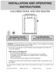
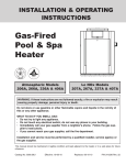
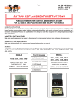
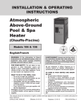
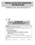
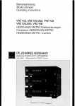
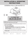
Tool Box
Quick Reference Guide
Raypak Digital Gas Pool Heaters
WATER CHEMISTRY
(Corrosive water voids all warranties)
For your health and the protection of your pool equipment, it is essential that your water
be chemically balanced. The following levels must be used as a guide for balanced water.
Recommended Levels
Fiberglass Pools
FiberGlass Spas
Other Pool & Spa Types
Water Temp. (Deg. F)
68 to 88
89 to 104
68 to 104
pH
7.3 to 7.4
7.3 to 7.4
7.6 to 7.8
Total Alkalinity (PPM)
120 to 150
120 to 150
80 to 120
Calcium Hardness (PPM)
200 to 300
150 to 200
200 to 400
Salt (PPM)
6000 MAXIMUM
6000 MAXIMUM
6000 MAXIMUM
Free Chlorine (PPM)*
2 to 3
2 to 3
2 to 3
Total Dissolved Solids (PPM)
3000 MAXIMUM
3000 MAXIMUM
3000 MAXIMUM
*Free Chlorine MUST NOT EXCEED 5PPM
2
• Occasional chemical shock dosing of the pool or spa water should not damage the heater providing
the water is balanced.
• Automatic chemical dosing devices and salt chlorinators are usually more efficient in heated water,
unless controlled, they can lead to excessive chlorine level which can damage your heater.
• Further advice should be obtained from your pool or spa builder, accredited pool shop, or chemical
supplier for the correct levels for your water
Model & Serial number
can also be found inside
the control panel above
digital display.
Model & Serial number
located on rating plate.
Alternate location
Before you call Raypak service, make sure you have the MODEL NUMBER and SERIAL NUMBER.
MODEL NUMBER & SERIAL NUMBER
Model Number and
Serial Number Location
3
Clearances - General
INDOOR
GENERAL CLEARANCES
TOP: Drafthood - 30”
RIGHT SIDE: 12”
LEFT SIDE: 6”
FRONT: Alcove (Open)
BACK: 6”
FLOOR: 0”
OUTDOOR
TOP: 36” (Stackless)
BACK: 6”
LEFT SIDE: 6”
RIGHT SIDE: 12”
FLOOR: 0”
FLOORING: THIS UNIT CAN BE INSTALLED ON COMBUSTIBLE FLOORING. DO NOT INSTALL ON CARPET.
4
4 ft.
Do not install near
sprinklers.
Do not install within
3 feet of a heat pump
pool heater or air conditioning condensing unit.
Minimum
4 ft.
Minimum
4 ft.
Minimum
3 ft.
Minimum
10 ft.
Minimum
1 ft.
Minimum
OUTDOOR CLEARANCES
Clearances - Outdoor
Forced Air Inlet
5
Clearances
-Indoor
10’ OR LESS
The heater must have both combustion
and ventilation air.
VENT CAP
2’ MIN
2’ MIN
INDOOR CLEARANCES
• Ventilation air opening 12” from the ceiling
• Combustion air opening 12” from the floor
All air from outdoors, each opening shall have
a net free area* as shown in table.
5’ MIN
VENT PIPE
* Effective open area of louvers or screens
6
Model
Unrestricted
opening
Sq. In. *
Typical
Screened or
Louvered
opening
Sq. In.
Typical
Screened and
Louvered
opening
Sq. In.
206/207
50
75
100
266/267
67
101
134
336/337
84
126
168
406/407
100
150
200
INDOOR
DRAFT HOOD
VENTILATION
AIR OPENING
COMBUSTION
AIR OPENING
HEATER
Check State and local codes before proceeding. Some States do not recognize the NFGC and require larger openings.
Gas Line Sizing
Maximum Equivalent Pipe Length
Natural Gas 1000 BTU/FT3
0.60 Specific Gravity @ 0.5 in. WC Pressure Drop
1.53 Specific Gravity @ 0.5 in. WC Pressure Drop
Input
3/4”
1”
1-1/4”
Model
(KBTU)
N
P
N
P
N
206/207
199.5
25
60
90
215
360
266/267
266.0
15
35
50
125
336/337
332.5
10
20
30
406/407
399.0
15
20
1-1/2”
P
N
210
480
445
80
140
320
290
55
95
225
215
P
480
GAS LINE SIZING
Propane Gas 2500 BTU/FT3
Effects of low gas pressure:
Pulsating burner flame • Delay Ignition/Hard light off • Pilot won’t light
Exposure to condensation • Emissions not at compliance levels
Damage to Low NOx burners
7
Gas Pressure Test
INLET GAS PRESSURE
MANIFOLD
GAS PRESSURE
Gas
Supply Press
GAS PRESSURE
Unit
Type
Min.
Max.
Man
Press
ATM
7”
14”
4.0”
NOx
7”
14”
3.1”
ATM
12”
14”
10.5”
Nat
6
GAS
VALVE
5
4
3
Pro
2
1
0
1
2
3
SLACK TUBE
MANOMETER
(INDICATES 8" W.C. AS SHOWN)
TO
BURNER
MANIFOLD
•Supply pressures given are under load
(dynamic)
• 1 PSI = 27.7” Water Column
4
5
6
8
• Propane requires an external “pounds to
inches regulator”
Gas Line Sediment Trap
INCORRECT
CORRECT
PROVIDE CHANGE OF DIRECTION IN GAS FLOW
GAS
COCK
(WITHIN 6 FEET
OF THE HEATER)
GAS
COCK
(WITHIN 6 FEET
OF THE HEATER)
UNION
UNION
GAS
VALVE
GAS
VALVE
REDUCER
REDUCER
RISER
RISER
AS CLOSE AS
PRACTICAL TO HEATER
GAS LINE SEDIMENT TRAP
Sediment Trap should be located as close to the inlet of the appliance as practical.
AS CLOSE AS
PRACTICAL TO HEATER
Check State and local codes before proceeding. Some States do not recognize the NFGC.
9
Power Connections
120V Lo NOx HEATER
HOT
L1
POWER CONNECTIONS
SUPPLY
SIDE
RETURN
or
NEUTRAL
BLACK
240V Lo NOx HEATER
BLACK
HOT
L1
BLACK
WHITE
WHITE
GREEN
WHITE
HEATER
7 WIRES
SUPPLY
SIDE
SUPPLY
SIDE
HOT
RED
RED
RED
GREEN
HEATER
7 WIRES
GREEN
WHITE
RED
WHITE
240V ATMOSPHERIC HEATER
HOT
RETURN
or
NEUTRAL
BLACK
RED
120V ATMOSPHERIC HEATER
L1
BLACK
L2
GROUND
GREEN
BLACK
HOT
BLACK
BLACK
WHITE
WHITE
GREEN
GREEN
L1
HEATER
4 WIRES
SUPPLY
SIDE
BLACK
BLACK
HOT
L2
RED
RED
GREEN
GREEN
HEATER
4 WIRES
GROUND
RED
10
WHITE
Note: Heater will not work properly if wired to a 208VAC power source.
Ignition and Temperature Control
VNT
GND
MV/PV
Low NOx
Tab and Fan
Wiring Connection
Spark - Flame Sensor
24 VAC
Power
Supply
Gas Control
Processor
GND
COMM
HOT
number
indicates
version
POOL
SPA
24V OUT
Remote
Connections
(Optional)
number indicates version
Water
Sensor
MODE
UP
DOWN
COMM
Main Processor
GND
GND
Propane
15 sec.
Tab
Keypad
Propane
90 sec.
tab
UT CIRCUIT BOARD
CLK SPR
PRS
PV
HL2
MV
HL1
ROLL OUT
Circuit Board
Gas
Valve
Safety Circuit
Program Switch
(re-boot button)
11
Sequence of Operations
SUPPLY (Power to Heater)
Sequence of Operations
12
1. 120/240 VAC from circuit breaker/time clock
2. 24 VAC out of transformer, toggle switch ON
3. 24VAC to MAIN PROCESSOR, LCD ON
APPLY 24 VAC to GAS PROCESSOR
1. CFH (CALL FOR HEAT) - POOL/SPA selected, Temperature Set, THERMOSTAT CLOSED
2. SAFETY CIRCUIT COMPLETED
(Pressure Switch, 2 High Limit Switches, Rollout Sensor CLOSED)
3. “ SPK” indicates POWER to GAS PROCESSOR
REPLY (Spark & 24VAC to Gas Valve)
1. Gas Processor replies with SPARK and PILOT voltage (Inner flame icon appears).
Pilot valve open, Gas supplied to pilot.
2. SPARK ignites pilot. Flame sensing occurs.
3. Gas Processor supplies voltage to close the Fan relay (Low NOx), FAN energizes, 30 seconds
until FAN proves, MV energized.
4. Normal operating display w/outer flame icon flashing, Main Valve Open,
2 Final pulses of Spark, Heater Fired.
EOL -Screen
EOL
EOL stands for End of Line Test.
EOL
This is a factory test procedure
mode used when doing the final live
fire test at the factory. This mode is
not used for field purposes.
To get a heater to display this mode, the unit must be off. Push and hold
down the MODE button. While holding down the button, turn the power on.
EOL will appear. To eliminate the EOL mode, turn the power off and then
back on.
If the EOL mode returns, it is most likely a bad keypad. To determine if the
keypad is bad, turn power off. Unplug keypad connector from circuit board.
Power unit on. If board goes into normal operation, the keypad is bad. If
EOL still appears, replace the board.
13
BDI -Screen
SERVICE
BDI
BDI is an indication of main
board failure.
If this code appears and stays on, turn off power to board at
toggle switch and source, then re-establish power.
If code reappears, replace board as the main processor failed to
start.
14
EEP -Screen
SERVICE
eep
EEP means there is a problem
accessing the memory chip.
EEP
EEP indicates that memory failed
to start on main processor. And
the main processor can’ t execute
the program with the supplied
data.
Turn off power at toggle switch and source and re-establish
power.
If code reappears, replace board as memory has failed.
BOARD ONLY REMEMBERS MODE,TEMPERATURE AND FAULTS.
15
PRS -Screen
SERVICE
PRS indicates low water pressure at the heater.
PRS
prs
1. Indicates possible low water flow through heater.
2. Check water level at skimmer face, should be middle of
skimmer face.
3. Check pump – is it running.
4. Check filter pressure – if 10 psi over clean filter reading,
backwash filter.
5. Check heater location – if more than 5 feet above or below water level
– adjust pressure switch.
6. The pressure switch is factory set to 1.75 psi for deck-level
and 5 feet below water level installations.
.
5 FT.
MAX
MAY REQUIRE ADJUSTMENT
FOR HIGHER PRESSURE
5 FT.
MAX
Part Number 006737F
16
Pressure Switch
MAY REQUIRE ADJUSTMENT
FOR LOWER PRESSURE
POOL OR SPA
A higher pressure rated (11psi) switch may be used for
installations outside the limits of a standard switch.
Use part number 009133F
HL1 & HL2 -Screen
SERVICE
hl1
HL1 & HL2 indicate the high-limit has
exceeded 135F.
1.
2.
3.
4.
5.
6.
Possible excessive water temperature in the tube bundle.
Once heater cools, high limits will reset automatically.
Check for blockage in tubes.
Check for low water flow.
Check UG – replace if necessary.
Check bypass assembly- replace spring or bypass if
necessary.
HL1/
HL2
Part Number 006725F
Hi Limit Switch
SERVICE
hl2
Part Number 006719F
Limed Tube
Unitherm Governor
17
ROL -Screen
ROL means the thermal fuse has tripped inside the
heater. This only trips when excessive heat or flame
roll-out is detected.
1.
2.
ROL
3.
4.
5.
Indicates possible downdraft of burner flame.
If sensor has red reset button, press button and
determine cause.
Does the unit need an outdoor high wind stack?
Check all wiring for indication of burnt wires,
especially the green ground wire and wires at gas valve.
Replace wires as necessary.
SERVICE
rol
Wind
2' MINIMUM
18
Part Number 005899F
Part Number 006035F
ATM Rollout Fuse
Low NOx Rollout Switch
Wind defense - high wind stack
SPR -Screen
spr
Note:
This is a “ spare” fault code.
This connection comes from
the factory with a jumper wire.
Any field installed safety device
such as a flow switch, draft
proving switch or special hilimit can be wired to this contact.
1. Used with flow switch for
Texas Code Kit (see below).
2. Failure of flow switch will
show as SPR.
SPR
19
SNS -Screen
SERVICE
SNS indicates the temp sensor is
out of acceptable range.
sns
1. Water temperature is below 36 º F
or above 110 º F.
2. The sensor contains two thermistors. If they are more than 2 degrees
SNS
apart an SNS failure will occur.
3. Loose or corroded connection at P1.
4. If the sensor is not mounted all the way into the JACO fitting on the
header it may give a false reading.
Sensor resistance at various temperatures
Temp Degrees F
Resistance (k)
20
40
50
60
70
80
90
100
106
Part Number 009577F
261.1 199.0 153.1 118.8 93.0 73.3 58.3 51.0
Replace sensor if not within 10% of values shown
Water Sensor - 100k Ohm
FFL -Screen
SERVICE
ffl
Indicates flame signal sensed at PILOT
before SPARK initiated and pilot established. FFL indicates a False Flame
Signal.
1. Check to see if pilot is staying lit after CFH is satisfied (main burner off). If pilot is
staying lit, the pilot valve in the gas valve is hanging open. Replace the gas valve.
2. If the gas valve is working properly, than the problem lies with the pilot
system or board. Turn power off at toggle switch.
3. Unplug the IGNITION WIRE from the board and pilot (if low NOx) and remove the
GREEN ground wire from burner tray, clean and reconnect ground wire.
4. Turn power on - if no Spark is observed at the Ignition Module, turn off power and
replace the BOARD and reconnect the ignition wire.
5. If Spark is observed at the Ignition Module, turn off the power and reconnect
the Ignition Wire.
6. Turn power on and unit should fire.
FFL
21
GVO & GVC -Screen
Indicates power found at either PV or MV at the
incorrect time (GVO), or if no power is detected at
PV or MV when commanded (GVC)
SERVICE
gvo
1. Turn OFF power and disconnect Ignition Wire and
Gas Valve wires from Board.
2. Turn power ON and WATCH for Spark at module.
3. If no Spark is observed, turn OFF power and REPLACE the BOARD.
4. If Spark is observed, turn off power and reconnect Gas Valve and
Ignition wire.
GVO/
5. Turn ON power and unit should fire.
GVC
6. If unit does not fire and code reappears, turn off power and disconnect Gas
Valve wires from the Board and remove MV, PV and
SERVICE
GROUND wires from the Gas Valve. Clean and
reconnect the wires.
7. Plug the Gas Valve back into the Board and turn the
power ON. The unit should fire.
8. If the unit
fails to fire, REPLACE THE GAS VALVE.
CHECK INCOMING POWER - Low power (208-220VAC) to the transformer can cause a GVO fault.
gvc
22
Fan -Screen
Low NOx Units
SERVICE
fan
Indicates that the Pilot was lost, or the air pressure switch is not
closed when required. On units with serial numbers 0707... or older,
Fan typically indicates loss of PILOT during MV operation. Units
newer than 0707 typically indicate Air Pressure Switch failure.
1. Check for correct incoming power at the fan relay – 120V or 240V and at the fan motor.
Note: Fan will not operate properly on 208V. Fan is wired before the transformer and can receive
either 120/240VAC (you can wire directly to the fan motor to check for proper operation of the fan).
2. If pilot has been confirmed, check for 24 volt minimum out of fan relay to air pressure switch.
3. If power is confirmed at the air pressure switch (purple wires) but the switch does not make when the
fan is operating, verify that the tubing between the fan housing and switch is connected and is not
kinked. If the switch remains inoperable, turn off power and replace the air pressure switch with the
correct setting for the unit (see page 38).
4. Restore power and wait for unit to start.
Note: Circuit board checks for pressure switch
closure 30 seconds after MV is powered.
5. Soft lock out after 3 attempts, automatically
resets after 5 minutes.
FAN
Tech Tip: The air pressure switch senses negative pressure
(suction). Testing the air switch by blowing on it will not
FAN/TAB Alternating Code -See TAB 2 screen
Air Pressure Switch
Blower/Fan
23
TAB -Screen
TAB indicates that either the board TAB for
Low Nox has not been broken, tab failed to
break off correctly or the air pressure switch
failed or is not connected.
TAB
1
24
SERVICE
ta
1. Check to make sure the White/Purple wire
is secure on male low NOx connector on
PC board.
2. Check to make sure the wire is secure on the air pressure switch.
Low NOx Tab
3. Turn off power to the board via the toggle switch.
4. Unplug the gas valve connector and ignition wire from the board.
5. Turn on power to the board and listen for spark at the ignition module.
6. If the board is sparking, turn off power and replace the air pressure
switch with correct setting switch for the unit (see page 38).
7. Plug in the gas valve connector and the ignition wire to the
ignition module.
8. Turn on the toggle switch and wait for the unit to start.
FAN/TAB Alternating Code & TAB Code Atmospheric-See TAB 2
TAB -Screen
SERVICE
ta
FAN/TAB Alternating Code – When these
two codes alternate back and forth with each
restart, they indicate a moisture condition within the Air Pressure Switch (APS). Disconnect
the APS and turn the switch so the air tube
adapter is pointing downward. Take note of any water flowing from the inside of the
switch. Replace the switch and reconnect all wiring and the orange air tubing, turn the
heater back on.
TAB Code Atmospheric – Raypak uses one board for Low NOx, Atmospheric and
Propane units. Replacement boards have a white/purple wire attached to the P-10 (Low
NOx) plug extension. This wire pigtail should be removed on all atmospheric and propane
units as it is capable of receiving energy from the spark wire at time of ignition. This will
result in a false TAB code, because these units are not Low NOx. On Low NOx units the
TAB
existing white/purple wire from the APS would be reattached to this terminal if a board
replacement is necessary.
2
25
IGN -Screen
IGN stands for Ignition Failure.
SERVICE
ign
Indicates loss of flame signal at
the pilot after main gas valve
power has been applied. The
board will reset itself and make three attempts on same CFH.
If the unit fails to hold flame after three attempts, it will go into a
hard lockout. Interrupt the power supply to clear the lock out and
check for air in the gas line or not enough gas pressure.
IGN IGN only appears after pilot has proved and main valve has
been powered.
26
ILO -Screen
SERVICE
ilo
ILO means Ignition Lock Out. This
only applies to propane units.
ILO
PROPANE - ILO is an indication that unit
failed to light the pilot within the 90 second trial for ignition.
Interrupt power to override the lock out. Check for air in
the gas line or low gas pressure.
If the propane tank is less than half full, there may not be
enough gas pressure.
Propane Tab
90 sec.
REPLACEMENT BOARDS MUST BE SET FOR
PROPANE USE. THE 90 SECOND TAB MUST BE
BROKEN.
Tech Tip: The most common cause for an ILO fault is an 27
CLK -Screen
CLK
CLOCK - Time Clock
Heater is OFF by programmed
control of a TIME CLOCK.
CLK
If a FIREMAN’ S SWITCH is connected, this
display is NORMAL, indicating TIME CLOCK
has turned the heater OFF 10-20 minutes prior
to turning the pump OFF. This is also referred
to as a “ cool down cycle” .
Time Clock
28
It is not unusual to see a remote wired into this
connection. This was common many years ago
before heaters had dedicated remote
connections.
Remote Wiring
Pool
Spa
24V Hot
REM
Part Number 071494
7-Pin Remote Wire Harness
Wire Harness Connected to Board
1. Pre-set Pool and Spa set point temperature.
(Set at 104°F if remote controller has built in T-Stat)
2. Select OFF Mode on control panel.
3. Remove Power; Connect the remote to the 7 pin
remote wire harness. Plug the wire harness into the
board. Re-apply power.
4. Hold all three buttons on the control panel down for
5-7 seconds until REMon appears. This will enable the
remote and disable the touch pad.
29
Fault History
File
WATER
TEMP
prs
SET
POINT
40
TEMP
MODE
FAULT HISTORY
The most recent service displays (up to 40) are retained in the
memory of the control.
1. Select OFF using Mode button.
2. Hold both Temp Set arrows down 6-7 seconds until the display
reads most recent fault code.
3. The display indicates the number of failures recorded (40 max).
4. Use the Temp Set arrows to scroll through recorded faults.
Service codes will display for about 6 seconds before reverting back to normal display.
30
Program Button
To
1.
2.
3.
4.
Allows for custom software
adjustments to meet job site needs.
initiate programming mode:
Select OFF Mode
Hold Program Button 5-7 seconds until “ SETdef” appears.
Press the Mode Button sequentially until the desired program event is reached.
There are 5 events that can be programmed.
Resets board to
factory default
settings
When SETdef appears on
the screen press and
hold both UP and DOWN
buttons for 5-7 seconds
until 3 dashes (---)
appear. Both pool and
spa set points revert to
65F.
Resets faults in
history file
When RESfl appears on
the screen press and
hold both UP and DOWN
buttons for 5-7 seconds
until 2 dashes (--)
appear. This clears fault
history to “0”.
Change from
Fahrenheit to
Celsius
When F/Cfff appears on
the screen press the UP
or DOWN button to toggle between “F” or “C”.
SPA- Set maximum set point
POOL- Set maximum set point
When SETspa 104
appears on the screen
press the UP or DOWN
button to your desired
maximum temperature
setting. The control can
be set for a maximum
of 107F.
When SETpool 104
appears on the screen
press the UP or DOWN
button to your desired
maximum temperature
setting. The control can
be set for a maximum
of 107F.
PROGRAM BUTTON
Programming
Button
31
Inlet-Outlet Header
High Limit 1
Temperature Sensor
P/N 006725F
P/N 009577F
INLET-OUTLET HEADER
Water Pressure Switch
P/N 006737F
High Limit 2
P/N 006725F
Unitherm Governor
P/N 006719F
Bypass Assy
P/N 006715F
32
Dam
P/N 006826F
Balancing Baffle
P/N 006826F
The UNITHERM GOVERNOR helps prevent
condensation and scale. It is a thermostatic
mixing valve used to control and regulate the
water temperature in the heat exchanger.
800366
U.G. Plug Gasket
O-Ring
006720F
U.G. Plug
006719F U.G.
800365 U.G. Gasket
Low temperatures in the exchanger can cause
condensation. This indicates that the heat
exchanger is running cool. This may be
caused by too much flow. Make sure the pump
is not supplying more than 125GPM. Also
check the U.G. to make sure it is working
properly and not damaged from chemical cor-
Elevated temperatures can cause scale. This may also produce a knocking sound and
high limit cycling. Make sure there is enough flow through the heater. Minimum flow rate
is 20-40GPM depending on model size. Also check and make sure the automatic bypass
is not missing or broken. Check the Unitherm Governor and make sure it is not frozen in
one position or chemically damaged. Tech Tip: You can test a U.G. by placing it in a cup
of hot water and watching it open up.
UNITHERM GOVERNOR
Unitherm Governor
33
Internal Bypass Valve
The Automatic Bypass Assembly allows the
heater to be connected to a wide variety of
pumps.
BYPASS VALVE
34
With every job site having different flow rates, the
Bypass automatically adjusts to provide the proper
flow rate to the heater, up to 125GPM max. If the flow
rate exceeds 125GPM condensation may form and
erosion of the copper tubes may occur. It is then recommended that an external bypass be installed before
the heater.
If the heater is making a knocking noise or cycling the
high limits, it may be that the Bypass is missing, stuck
open or damaged. It is also possible that the wrong
Bypass spring is installed. See table for correct
206/207
266/267
336/337
406/407
Color
Blue
Red
Silver
Silver
Part Number
006718F
006718F
006718F
006718F
Tech Tip:
You can feel the Bypass by placing
your fingers down into the inlet of
the header. You can feel the Bypass
spring back as you push on it.
Flow Rates and Pressure Drops
Plastic Internal Baffle - Manufactured after 11/08
Cast Iron Header (ASME Models)
Pressure Drop (Ft of Head)
Flow
GPM
206/207
20
1.8
30
2.2
8.0
336/337
406/407
9.0
9.0
9.0
2.7
9.8
9.8
9.8
60
3.3
10.5
10.5
10.5
5.2
70
4.3
11.0
11.0
11.0
6.9
6.9
80
5.5
11.5
11.5
11.5
6.9
6.9
6.9
90
6.8
14.0
14.0
14.0
4.6
8.1
9.2
9.2
100
8.2
17.0
17.0
17.0
80
4.6
9.2
9.8
9.8
90
6.9
10.4
10.4
10.4
100
8.1
11.0
12.1
12.1
110
10.4
11.5
13.3
13.3
120
11.0
12.7
17.9
17.9
125
11.5
13.8
20.2
20.2
Pressure Drop (Ft of Head)
Flow
GPM
206/207
20
4.0
25
4.0
4.6
40
2.5
30
4.0
5.2
50
35
4.0
5.8
5.2
40
4.6
5.8
5.2
50
4.6
6.3
60
4.6
70
266/267
336/337
406/407
266/267
Flow Rates
Model
Min GPM
Max GPM
206/207
20
125
266/267
25
125
336/337
35
125
406/407
40
125
FLOW RATES & PRESS DROPS
Polymer Header (Standard Models)
35
Pilot Assemblies -Spark Gap
0.156 ± .04
PILOT ASSEMBLIES
0.125 ± .015
Atmospheric Pilot
36
0.18 ± .04
Low NOx Pilot
This photo illustrates the
correct installation of a PRV
on the larger models.
Two street elbows are used
to move the larger PRV’ s
away from the access panels. Smaller PRV’ s can be
mounted directly into the
header.
PRV INSTALLATION
PRV Installation
37
Low NOx Air Pressure Switch
There are 4 different air pressure switches for the Low NOx
heaters. None of the switches are interchangeable.
LOW NOx AIR SWITCH
38
Each switch has a colored decal to help identify the switch. See
chart below for proper switch choice.
Tech Tip: The air pressure switch senses
negative pressure (suction). Testing the air
switch by blowing on it will not work. You
need to apply light suction.
207
267
337
407
Color
Blue
Red
Yellow
Green
Part Number
008062F
008135F
010354F
010355F
Notes
39
Tool Box
Quick Reference Guide
WWW.RAYPAK.COM
Check our FAQ section on our website for answers to common problems.
EMAIL us with technical questions, we pride ourselves on quick answers.
BEFORE YOU CALL
What is the incoming power 120 or 240VAC? 208 will not work properly.
What is the power at the circuit board?
What is the incoming gas pressure?
If the unit can fire, what is the pressure at the manifold (burner pressure)?
Is the gas line rigid or flex-line?
THIS IS NOT A SUBSTITUTE FOR THE INSTALLATION AND OPERATION MANUAL.
THIS MANUAL IS INTENDED TO HELP THE SERVICE TECHNICIAN WITH BASIC TROUBLESHOOTING.
40
Raypak, Inc. 2151 Eastman Avenue • Oxnard, CA 93030 • 805-278-5300