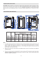
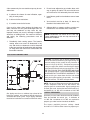
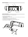
1
INSTALLATION & OPERATING
INSTRUCTIONS
84 Professional
Gas-Fired
Pool & Spa
Heater
Low NOx Models
259 & 409
WARNING: If these instructions are not followed exactly, a fire or explosion may result
causing property damage, personal injury or death.
Do not store or use gasoline or other flammable vapors and liquids in the vicinity of
this or any other appliance.
WHAT TO DO IF YOU SMELL GAS:
• Do not try to light any appliance.
• Do not touch any electrical switch; do not use any phone in your building.
• Immediately call your gas supplier from a neighbor's phone. Follow the gas supplier's instructions.
• If you cannot reach your gas supplier, call the fire department.
Installation and service must be performed by a qualified installer, service agency or
the gas supplier.
This manual should be maintained in legible condition and kept adjacent to the heater or in a safe place for future
reference.
Catalog No. 6000.65A
Effective: 12-06-12
Replaces: 05-17-12
P/N 241464 Rev. 2
WATER CHEMISTRY
(Corrosive water voids all warranties)
For your health and the protection of your pool equipment, it is essential that your
water be chemically balanced. The following levels must be used as a guide for balanced water.
Recommended Level(s)
Water Temp. (Deg. F)
pH
Total Alkalinity (PPM)
Calcium Hardness (PPM)
Salt (PPM)
Free Chlorine (PPM)*
Fiberglass Pools
Fiberglass Spas
Other Pool & Spa
Types
7.3 to 7.4
7.3 to 7.4
7.6 to 7.8
68 to 88
89 to 104
120 to 150
120 to 150
4500 MAXIMUM
4500 MAXIMUM
200 to 300
2 to 3
150 to 200
2 to 3
Total Dissolved Solids (PPM) 3000 MAXIMUM** 3000 MAXIMUM**
* Free Chlorine MUST NOT EXCEED 5 PPM!
68 to 104
80 to 120
200 to 400
4500 MAXIMUM
2 to 3
3000 MAXIMUM**
** In salt water chlorinated pools, the total TDS can be as high as 6000 ppm.
•
•
•
Occasional chemical shock dosing of the pool or spa water should not damage the
heater providing the water is balanced.
Automatic chemical dosing devices and salt chlorinators are usually more efficient
in heated water, unless controlled, they can lead to excessive chlorine level which
can damage your heater, and which is not covered under warranty. A check
valve should be installed between the heater outlet and a chlorinator or other chemical dosing device.
Further advice should be obtained from your pool or spa builder, accredited pool
shop, or chemical supplier for the correct levels for your water.
Rev. 2 reflects the following:
Changes to: Contents on page 3, Introduction and Start-Up Procedure on page 5, Receiving Equipment on
page 9, Loose Plumbing Parts diagram on page 9 (moved from page 30), Florida tie-down diagram on page 13,
Specifications and Dimensions on page 14, Vent/Inlet Termination Clearances on page 15, Direct Vent instructions on page 16, Venting Category Requirements on page 17, Category I installation on pages 19-20, Horizontal
Venting diagrams on page 21, Vertical Direct Vent diagram on page 22, Outdoor Installation on page 23,
Plumbing Connections on page 28, Status and Diagnostics on page 37, Orifice Removal diagram on page 41,
Igniter Removal on page 41, Troubleshooting on page 42, Control Logic flow chart on page 43, Illustrated Parts
List on pages 44-46
Additions: Table and Direct Vent - Horizontal instructions on page 21, Piping diagrams on page 30, Gas and
Air Orifice Selection on page 41
Deletions: None
2
2
4
4
5
5
6
6
7
8
8
8
8
9
9
10
10
10
11
11
13
14
14
16
16
17
18
18
19
19
19
21
22
23
24
24
25
25
25
25
25
25
26
26
27
28
28
Water Chemistry
WARNINGS
Pay Attention to These Terms
CONTENTS
Wiring Diagram
33
34
34
35
37
38
38
38
39
39
39
40
40
40
40
41
41
41
41
General Location of Controls
Control Adjustments
Control Panel Removal
Thermostat Operation - Direct Spark Board
Status and Diagnostics
Remote Control Installation and Operation
Remote Operation
Activating the Remote
Remote Control Wiring
2-Wire Remote Control
3-Wire Remote Control
Time Clock / Fireman’s Switch
High Limits
Flow Switch
Air Pressure & Blocked Vent Switches
Visual Inspection
Electrical
Orifice Removal
Igniter Removal
42
43
Mechanical
Control Logic - Flow Chart
44
45
47
Illustrated Parts List
Part Numbers
Important Instructions for the
Commonwealth of Massachusetts
33
PART ONE
OWNER'S OPERATING INSTRUCTIONS
SECTION 1
START-UP PROCEDURES
SECTION 2
CAUTION
SECTION 3
MAINTENANCE & CARE PROCEDURES
Lighting & Shutdown Instructions
Pool & Spa Water Chemistry
Automatic Chlorinators & Chemical Feeders
Cold Weather Operation
Winterizing the Pool & Spa Heater
PART TWO
INSTALLATION & SERVICE INSTRUCTIONS
SECTION 1
RECEIVING EQUIPMENT
SECTION 2
GENERAL SPECIFICATIONS
SECTION 3
INSTALLATION INSTRUCTIONS
Code Requirements
Clearances
Outdoor Heater Installation
Florida Building Code
Indoor Heater Installation
Specifications and Dimensions
Combustion and Ventilation Air
Direct Vent
Venting
Support of Vent Stack
Vent Terminal Location
Venting Installation Tips
Venting Configurations
Natural Draft Vertical Venting (Category I)
Horizontal Through-the-Wall Direct Venting
(Category III)
Direct Vent - Vertical
Outdoor Installation
Gas Supply Connections
Gas Pressure Adjustment Locations
Pipe Sizing For Gas Connections
Flow Rates
Heat Exchanger Pressure Drop Tables
Internal Automatic Bypass Valve
External Auxiliary Bypass Valve
Auxiliary Bypass Valve Adjustment
Pressure Relief Valve Installation
Electrical Wiring
Transformer Wiring
Optional Left-Hand Wiring
Plumbing—Water Connections
32
42
44
3
SECTION 4
SERVICING INSTRUCTIONS
SECTION 5
TROUBLESHOOTING
SECTION 6
REPLACEMENT PARTS
WARNINGS—Pay Attention to These Terms
DANGER:
WARNING:
CAUTION:
NOTE:
Indicates the presence of immediate hazards which will cause severe
personal injury, death or substantial property damage if ignored.
Indicates the presence of hazards or unsafe practices which could cause
severe personal injury, death or substantial property damage if ignored.
Indicates the presence of hazards or unsafe practices which could cause
minor personal injury or product or property damage if ignored.
Indicates special instructions on installation, operation, or maintenance which
are important but not related to personal injury hazards.
DANGER: Failure to install the draft hood on indoor
installations and properly vent the heater to the
outdoors as outlined in the Venting section of this
manual can result in unsafe operation of the heater.
To avoid the risk of fire, explosion, or asphyxiation
from carbon monoxide, never operate this heater
unless it is properly vented and has an adequate air
supply for proper operation. Be sure to inspect the
vent system for proper installation at initial start-up;
and at least annually thereafter. Refer to the
Maintenance section of this manual for more
information regarding vent system inspections.
WARNING: Both natural gas and propane have an
odorant added to aid in detecting a gas leak. Some
people may not physically be able to smell or
recognize this odorant. If you are unsure or
unfamiliar with the smell of natural gas or propane,
ask your local gas supplier. Other conditions, such
as "odorant fade," which causes the odorant to
diminish in intensity, can also hide, camouflage, or
otherwise make detecting a gas leak by smell more
difficult.
WARNING: UL recognized fuel gas detectors are
recommended in all enclosed propane and natural
gas applications wherein there is a potential for an
explosive mixture of fuel gas to accumulate and their
installation should be in accordance with the
detector manufacturer's recommendations and/or
local laws, rules, regulations, or customs.
DANGER: Make sure the gas on which the heater
will operate is the same type as that specified on the
heater rating plate.
DANGER: When servicing or replacing components
that are in direct contact with the water, be certain
that:
• There is no pressure in the heater. (Pull the release
on the relief valve. Do not depend on the pressure
gauge reading).
• The heater water is not hot.
• The electrical power is off.
WARNING - CALIFORNIA PROPOSITION
65: This product contains chemicals known to the
State of California to cause cancer, birth defects or
other reproductive harm.
WARNING: This product must be installed by a
licensed plumber or gas fitter when installed within
the Commonwealth of Massachusetts.
WARNING: All venting types must be of the same
material or product throughout the entire exhaust
installation to ensure proper securing and sealing.
WARNING: Do not install within 3 feet of a heat
pump or an outdoor condensing unit. Strong air
intake from this type of equipment can disturb the
combustion process and cause damage or personal
injury.
WARNING: Altering any Raypak pressure vessel
by installing replacement heat exchangers, tube
bundle headers, or any ASME parts not
manufactured and/or approved by Raypak will
instantly void the ASME and/or CSA ratings of the
vessel and any Raypak warranty on the vessel.
Altering the ASME and/or CSA ratings of the vessel
also violates national, state, and local approval
codes.
WARNING: Do not use this heater if any part has
been under water. Immediately call a qualified
service technician to inspect the heater and to
replace any part of the control system and any gas
control which has been under water.
4
PART ONE
OWNER'S OPERATING INSTRUCTIONS
FOR YOUR SAFETY - READ BEFORE OPERATING
WARNING: IF YOU DO NOT FOLLOW THESE INSTRUCTIONS EXACTLY, A FIRE OR EXPLOSION MAY
RESULT, CAUSING PROPERTY DAMAGE, PERSONAL INJURY OR LOSS OF LIFE.
INTRODUCTION
Your pool/spa heater has been designed for years of safe and reliable pool/spa water heating. It is available with
electronic ignition. This manual provides installation, operation, maintenance, and service information for these
heaters.
ON
If your heater has been installed correctly, operating the heater is an easy task. The upper front panel of the
heater contains the control center that allows you to turn the heater On or Off and adjust the temperature settings for the pool or spa. The temperature range is factory set from 50°F (18°C) to 104°F (40°C). See figure
above for location of toggle switch to turn the heater On and Off. Section 4 of this manual contains more details
about the use of the controls in the Control Adjustments subsection (page 34).
OFF
SECTION 1 - START-UP PROCEDURE
1. Clean air louvers of dust, lint and debris.
2. Keep heater area clear and free from combustibles, flammable liquids and chemicals.
3. Verify that the flow of combustion and ventilation
air is not obstructed.
4. Water must be flowing through the heater during
operation. Ensure that the system is filled with
water and the pump is operating. Double check
for any water leaks.
5. Purge air from the gas line. Insufficient purging
may keep the heater from lighting on the first try.
6. Double check gas connections, make sure no
leaks are present. Use soapy water to inspect.
7. Double check incoming electrical power, verify sufficient output voltage to the heater.
8. The unit comes wired for 240VAC power. If the
supply voltage is nominally 120V, switch blower
harness located inside the cabinet (see wiring diagram).
9. If installed indoors, make sure flue gases are vented properly, and that combustion and makeup air
openings are adequate.
10. Locate and turn the gas valve ON.
11. Locate the plugged bleedle valve off the right side
of the gas valve.
12. Remove the bleedle plug and connect a manometer to the valve.
13. Locate and flip the display lid upwards.
14. Turn the heater on, by pressing the ON/OFF tog-
gle switch on the front display.
15. Set the mode to either SPA or POOL.
16. If the set point is higher than the current temperature, the heater will begin its startup sequence.
17. The ignition control will verify that the blower air
switch is open before starting the blower. Once
proven open, the blower will be powered to start
the ignition sequence. Verify suction pressure
matches the table below, Blower Suction
Pressure, for your model heater during the prepurge period.
18. Once the blower air switch proves, a 45 second
pre-purge period will begin to purge residual
gases from the combustion chamber.
Model
Elevation
Blower Suction
259
2000-5000 ft.
-3.1 to -3.6 "WC
409
5
0-2000 ft.
5000-7000 ft.
0-2000 ft.
2000-5000 ft.
5000-7000 ft.
-3.5 to -3.8 "WC
-2.8 to -3.2 "WC
-3.7 to -4.0 "WC
-3.3 to -3.8 "WC
-3.0 to -3.4 "WC
Blower Suction Pressure
19. Once the pre-purge period ends, the igniter will
begin to spark just prior to the gas valve opening.
The gas valve will open for a 4 second trial for ignition. If flame is proven, the heater will operate to
meet heat demand. If flame is not proven, the
heater will enter a post-purge period and then retry
the ignition cycle or lockout, depending on the
heater configuration.
20. Once gas is flowing, the manometer reading will
drop to -0.40” +/- .1” WC.
21. Visually check through the sight glass that the
heater is on and heating. A yellowish glow coming
from the refractory indicates that the heater is running. The flame should be a blueish color.
22. Remove the manometer and replace with bleedle
plug.
23. Reinstall front door panel and knurled screw holding the door in place.
24. Feel the inlet and outlet pipes. Outlet pipe should
be only slightly warmer than the inlet. It should not
be hot.
5. Persons with a medical history of heart disease, circulatory problems, diabetes, or blood pressure
problems should obtain a physician's advice before
using pools or hot tubs.
6. Persons taking medications which induce drowsiness, such as tranquilizers, antihistamines, or anticoagulants, should not use spas or hot tubs.
SECTION 3 - MAINTENANCE AND
CARE PROCEDURES
WARNING: Check the heater for possible rodent
nests after long periods of non-use.
To be followed one month after start-up and then semiannually.
1. Inspect and operate all controls, gas valve and
pressure relief valve.
2. On indoor heaters, clean room intake openings to
ensure adequate flow of combustion and ventilation air.
SECTION 2 - CAUTION
Elevated water temperature can be hazardous. The
U.S. Consumer Product Safety Commission has these
guidelines:
CAUTION: Combustion air must not be contaminated by corrosive chemical fumes which can damage
the heater and void the warranty.
1. Spa water temperatures should never exceed
104°F (40°C). A temperature of 100°F (38°C) is
considered safe for a healthy adult. Special caution
is suggested for young children.
3. Keep area around heater clear and free from combustible materials, gasoline and other flammable
and corrosive vapors and liquids.
IF HEATER WILL NOT FIRE:
2. Drinking of alcoholic beverages before or during
spa or hot tub use can cause drowsiness which
could lead to unconsciousness and subsequently
result in drowning.
If you have no electrical power, it may be that your
"circuit breaker" has tripped. Try re-setting it.
3. Pregnant Women Beware! Soaking in water over
102°F (39°C) can cause fetal damage during the
first three months of pregnancy resulting in the birth
of a brain-damaged or deformed child. Pregnant
women should stick to the 100°F (38°C) maximum
rule.
If you have electrical power but the heater will not fire
check the following or see Troubleshooting section:
1. The time clock must be in the "ON" position.
2. Your pump strainer basket may be full.
remove debris.
4. Before entering the spa or hot tub, users should
check the water temperature with an accurate thermometer; spa or hot tub thermostats may err in regulating water temperatures by as much as 4°F
(2.2°C).
If so
3. Your filter may be dirty. If so, backwash or clean
filter. (To tell if your filter is dirty, look to see if the
filter pressure will be higher than usual).
4. The pump may have lost its prime and be running
dry. Check the pressure on the filter. If there is no
pressure; then you are not moving water (or your
gauge is broken). Try to get the pump to run at its
normal flow rate.
6
WARNING: Should overheating occur or the gas supply fail to shut off, turn off the manual gas control to the
heater.
CAUTION: Propane gas is heavier than air and will settle on the ground. Since propane can accumulate in
confined areas, extra care should be exercised when lighting propane heaters.
7
POOL & SPA WATER CHEMISTRY
COLD CLIMATE: Prolonged operation with water
temperatures below 50°F is not recommended.
When starting the heater with water temperatures
below 50°F, operate the heater continuously until
higher temperatures are reached. Operating the
heater for prolonged periods with pool water below
50°F can seriously damage the heater, and is not covered by the warranty.
Chemical imbalance can cause severe damage to
your heater and associated equipment. Maintain
your water chemistry according to the chart on page 2.
If the mineral content and dissolved solids in the water
become too high, scale forms inside the heat exchanger tube, reducing heater efficiency and damaging the
heater. If the pH drops below 7.2, this will cause corrosion of the heat exchanger and severely damage the
heater. Heat exchanger damage resulting from
chemical imbalance is not covered by the warranty.
For cold climate areas, please follow the winterizing
procedures listed.
WINTERIZING THE POOL & SPA HEATER
AUTOMATIC CHLORINATORS AND
CHEMICAL FEEDERS
Heaters installed outdoors in freezing climate areas
may be shut down for the winter. Observe the following procedure for winterizing the heater:
All chemicals must be introduced and completely diluted into the pool or spa water before being circulated
through the heater. Do not place sanitizing chemicals
in the skimmer. High chemical concentrations will
result when the pump is not running (e.g. overnight).
1. Turn off gas valve, manual gas valve, and electrical supply to the heater.
2. Open the drain valve located on the inlet/outlet
header (at the lowest point). Pull the PRV handle
upwards to allow air in while the water drains
through the valve.
Chlorinators must feed downstream of the heater and
have an anti-siphoning device to prevent chemical
back-up into the heater when the pump is shut off. A
check valve should be installed between the heater
outlet and the chlorinator.
See plumbing diagrams on page 30 and 31.
NOTE: High chemical concentrates from feeders and
chlorinators that are out of adjustment will cause rapid
corrosion to the heat exchanger. Such damage is not
covered under the warranty.
COLD WEATHER OPERATION
IMPORTANT FREEZE INFORMATION
MODERATE CLIMATE: Heater operation can continue during short-term cold spells. When temperatures
are between 0°F and 32°F, flow (continuous pump
operation) must be maintained.
CAUTION: Do not use the heater to maintain water
temperatures just above freezing or for freeze protection. When heater is used during freezing weather,
care must be taken to avoid freeze-ups. Continuous
pump operation is a must. Additional protection may
be required. The heater is not warranted against
freeze-ups.
8
PART TWO
INSTALLATION AND SERVICE INSTRUCTIONS
SECTION 1 - RECEIVING EQUIPMENT
The manufacturer recommends that this manual be reviewed thoroughly before installing your pool/spa heater.
If there are any questions that this manual does not answer, please contact the factory or your local representative.
On receipt of your equipment it is suggested that you visually check for external damage to the carton. If the
carton is damaged, a note should be made on the Bill of Lading when signing for the equipment. Remove the
heater from the carton. If it is damaged, report the damage to the carrier immediately. Save the carton.
These items are shipped inside a box in the carton with the heater:
STANDARD UNIT
1. Plastic pipe finish flange for gas line
2. Bonding lug with mounting screw
3. 2” CPVC Slip x Slip 8-3/16” Nipple
4. 2” CPVC Slip x Slip 7” Nipple
5. (2) 2” CPVC/PVC unions with "O" rings
6.
7.
8.
9.
(2)
(2)
(2)
(2)
2” CPVC Ring Nuts
“O” rings
2” CPVC tail pieces
3-1/2” Vinyl Grommets
SLIP
2” TAIL PIECE
CPVC NIPPLE
O-RING
SLIP
2” TAIL PIECE
O-RING
BUTTRESS
TAIL PIECE
2” RING NUT
VINYL GROMMET
2” RING NUT
Be sure that you receive the number of packages indicated on the Bill of Lading.
When ordering parts, you must specify the model and serial numbers of the heater. See below for location of
serial number. When ordering under warranty conditions, you must also specify date of installation.
The Model & Serial No.
can also be found inside
the bezel above the display
Model & Serial No.
Located on Rating
Plate
LABEL ON CARTON
SERIAL NUMBER
9
SECTION 2 - GENERAL SPECIFICATIONS
These heaters are design-certified and tested under the latest requirements of the ANSI Z21.56 / CSA 4.7
Standard for Gas-Fired Pool Heaters. All heaters can be used either indoor or outdoors.
Ambient Temperature Rating of Heater Components
-32°F to + 175°F
Electronic Ignition Heater*
*Requires 120 or 240VAC Power Supply
Rated inputs are suitable for up to 2,000 feet elevation. The input will be reduced by approximately 4% for each
1,000 feet above 2,000 feet, as high elevation reduces combustion performance.
SECTION 3 - INSTALLATION INSTRUCTIONS
CALIFORNIA PROPOSITION 65 WARNING: This product contains chemicals known to the State of California
to cause cancer, birth defects or other reproductive harm.
WARNING: This unit contains refractory ceramic fiber (RCF) insulation in the combustion chamber. RCF, as
manufactured, does not contain respirable crystalline silica. However, following sustained exposure to very
high temperatures (>2192°F), the RCF can transform into crystalline silica (cristabolite). The International
Agency for Research on Cancer (IARC) has classified the inhalation of crystalline silica (cristabolite) as carcinogenic to humans.
When removing the burner or heat exchanger, take precautions to avoid creating airborne dust and avoid
inhaling airborne fibers. When cleaning spills, use wet sweeping or High Efficiency Particulate Air (HEPA)
filtered vacuum to minimize airborne dust. Use feasible engineering controls such as local exhaust ventilation
or dust collecting systems to minimize airborne dust. Wear appropriate personal protective equipment
including gloves, safety glasses with side shields, and appropriate NIOSH certified respiratory protection, to
avoid inhalation of airborne dust and airborne fiber particles.
IMPORTANT NOTICE
These instructions are intended only for the use by qualified personnel, specifically trained and experienced in the installation of this type of heating equipment and related system components. Installation
and service personnel may be required by some states to be licensed. If your state is such, be sure your contractor bears the appropriate license. Persons not qualified shall not attempt to fix this equipment nor attempt
repairs according to these instructions.
WARNING: Improper installation, adjustment, alteration, service or maintenance may damage the equipment, create a hazard resulting in asphyxiation, explosion or fire, and will void the warranty.
CODE REQUIREMENTS
NOTE: The heater should not be located in an area where possible water leakage will result in damage to the
area adjacent to the heater or to the structure. When such locations cannot be avoided, it is recommended that
a suitable drain pan, with adequate drainage, be installed under the heater. The pan must not restrict combustion air flow.
Installation must be in accordance with local codes, or, in the absence of local codes, with the latest edition of
the National Fuel Gas Code, ANSI Z223.1/NFPA54 and National Electrical Code, ANSI/NFPA 70, and for
Canada, the latest edition of CAN/CSA-B149 Installation Codes, and Canadian Electrical Code, CSA C22.1
Part 1 and Part 2.
10
CLEARANCES
ALL HEATERS
For clearances from combustible surfaces, see the
chart below.
When installed according to the listed minimum clearances from combustible construction, the pool heater
can still be serviced without removing permanent
construction around the heater.
CLEARANCE FROM
COMBUSTIBLE CONSTRUCTION
However, for ease of servicing, Raypak recommends a clearance of at least 24” in the front and
at least 18" on the water connection side. This will
enable the heater to be serviced in its installed location, that is, without movement or removal of the
heater.
INDOOR INSTALLATIONS:
Top* - 30”
Back - 1”
Front - Alcove (Open) Right Side - 1”
Vent - 1”
Left Side - 1”
Floor** - 0”
OUTDOOR INSTALLATION - TOP EXHAUST
Top* - Unobstructed (Outdoor Stack)
Floor - 0”
Right Side - 8”
Back - 6”
Left Side - 8”
The heater must be installed in a manner that will
enable the heater to be serviced without removing any
structure around the heater.
FLOORING: This heater can be installed on combustible flooring.
OUTDOOR INSTALLATION - REAR EXHAUST
Top* - Unobstructed
Floor - 0”
Right Side - 8”
Back - 12”
Left Side - 8”
*Clearance from top of vent terminal.
**Do not install on carpeting.
OUTDOOR HEATER INSTALLATION
These heaters are design-certified for outdoor installation, when equipped with the approved tops designated for
outdoor use.
WARNING: The heater shall not be located in an area where water sprinklers, or other devices, may cause
water to spray through the cabinet louvers and into the heater. This could cause internal rusting or damage
electrical components, and void the warranty.
WARNING: Do not install within 3 feet of a heat pump or an outdoor condensing unit. Strong air intake from
this type of equipment can disturb the combustion process and cause damage or personal injury.
11
Heaters must not be installed under an overhang of less than three 3 ft from the top of the heater. Three sides
must be open in the area under the overhang. Roof water drainage must be diverted away from the heaters
installed under overhangs with the use of gutters.
For U.S. installations, the point from where the flue products exit the heater must be a minimum of 4 ft below,
4 ft horizontally from, or 1 ft above any door, window or gravity inlet into any building. The top surface of the
heater shall be at least 3 ft above any forced air inlet, or intake ducts located within 10 ft horizontally.
For installations in Canada, pool heaters shall not be installed with the top of the vent assembly within 10 ft
below, or to either side, of any opening into the building. Refer to the latest revisions of CAN/CSA-B149.
4 ft
Minimum
3 ft
4 ft
Minimum
4 ft
Minimum
Minimum
10 ft
1 ft
Minimum
Minimum
Forced Air Inlet
For installations in Florida and Texas, that must comply with the Florida or Texas Building Code, follow the
directions on page 13 for the installation of hurricane tie-down method for all models.
12
13
INDOOR HEATER INSTALLATION
For Canada, indoor installation is restricted to an enclosure that is not occupied and does not directly communicate with an occupied area. Refer to the latest edition of CAN/CSA-B149 for specific requirements. Locate
heater as close as is practical to a chimney or gas vent. The heater must always be vented to the outside.
See the Venting section (beginning on page 17) for details. Minimum allowable space is shown on the nameplate.
SPECIFICATIONS AND DIMENSIONS
Heater
Model
MBTU
Input
Flue
Diameter
(B)
BR-409
399.0
6”
BR-259
Notes:
1.
2.
3.
250.0
6”
Dimensions (in.)
Air Inlet
(C)
4”
4”
Shipping
Minimum Maximum Weight (lbs)
Flow
Flow
w/ Stackless
(gpm)
(gpm)
Top
25
40
125
125
193
205
The model number prefix indicates: (B=Bronze header), (R=Raypak) Model number suffix indicates: pilot
type (E = digital) and fuel type (P = propane, N = natural gas) fin tubing (X=Cupro-Nickel, C= Copper).
Example: Model number BR-409-EN-X indicates a unit with digital (IID) ignition using natural gas with
bronze headers and cupro-nickel tubes.
Ratings are for natural gas and elevations up to 2,000 feet above sea level. For elevations over 2,000 feet,
consult the factory.
Flue gases must be properly vented with CAT I vertical venting or CAT III horizontal venting. Non-metallic
venting not acceptable. Inlet air can be ducted with 4” metal or PVC pipe. See the venting section of this
manual for complete venting details.
14
Minimum Clearances from Vent/Air Inlet Terminations – Indoor and Outdoor Installations
1
1
2
t
TT
*
2
U.S. Installations
Canadian Installations
A
Clearance above grade, veranda, porch,
deck, or balcony
1 ft (30 cm)
1 ft (30 cm)
B
Clearance to window or door that may be
opened
4 ft (1.2m) below or to side
of opening; 1 foot (30 cm)
above opening
3 ft (91 cm)
C
Clearance to permanently closed window
*
*
D
Vertical clearance to ventilated soffit located
above the terminal within a horizontal distance of 2 ft (61cm) from the centerline of the
terminal
5 ft (1.5m)
*
E
Clearance to unventilated soffit
*
*
*
*
6 ft (1.83m)
*
3 ft (91 cm) within a
height 15 ft above the
meter/regulator assembly
F
Clearance to outside corner
G
Clearance to inside corner
H
Clearance to each side of center line extended above meter/regulator assembly
*
I
Clearance to service regulator vent outlet
*
3 ft (91cm)
J
Clearance to non-mechanical air supply inlet
to building or the combustion air inlet to any
other appliance
4 ft (1.2m) below or to side
of opening; 1 ft (30 cm)
above opening
3 ft (91 cm)
K
Clearance to mechanical air supply inlet
3 ft (91 cm) above if within
10 ft (3m) horizontally
6 ft (1.83m)
L
Clearance above paved sidewalk or paved
driveway located on public property
7 ft (2.13m)
7 ft (2.13m) t
M
Clearance under veranda, porch, deck or
balcony
*
12 in. (30 cm) TT
In accordance with the current ANSI Z223.1/NFPA 54 National Fuel Gas Code
In accordance with the current CAN/CSA-B149 Installation Codes
Vent terminal shall not terminate directly above sidewalk or paved driveway located between 2 single family dwellings that serves
both dwellings
Permitted only if veranda, porch, deck, or balcony is fully open on a minimum of two sides beneath the floor and top of terminal and
underside of veranda, porch, deck or balcony is greater than 1 ft (30cm)
Clearances in accordance with local installation codes and the requirements of the gas supplier
Vent/Air Inlet Termination Clearances
15
COMBUSTION AND VENTILATION AIR (Indoor Units Only)
The heater must have both combustion and ventilation air. Minimum requirements for net free air supply openings are one opening that is 12 inches from the ceiling for ventilation, and one opening that is 12 inches from the
floor for combustion air as outlined in the latest edition of the National Fuel Gas Code, ANSI Z223.1(CanadaCAN/CSA-B149) and any local codes that may have jurisdiction.
A. All Air From Inside The Building:
Each opening shall have a minimum net free area as noted:
Model
259
400
Square Inches
250
399
B. All Air From Outdoors:
When air is supplied directly from outside the building, each opening shall have a minimum net free area
as noted:
Model
Unrestricted Opening (sq. in.)
Typical Screened or
Louvered Opening (sq. in.)
Typical Screened and
Louvered Opening (sq. in.)
409
100
150
200
259
63
95
126
CAUTION: Combustion air must not be contaminated by corrosive chemical fumes which can damage the
heater and void the warranty.
Direct Vent
If outside air is drawn through the intake pipe directly to the unit for combustion:
1. Install combustion air direct vent in accordance on page 21 (horizontal) or page 22 (vertical) of this manual.
2. Provide adequate ventilation of the space occupied by the heater(s) by an opening(s) for ventilation air at
the highest practical point communicating with the outdoors.
a) In the US, the total cross-sectional area shall be at least 1 in.2 of free area per 20,000 BTUH (111 mm2
per kW) of total input rating of all equipment in the room when the opening is communicating directly
with the outdoors or through vertical duct(s). The total cross-sectional area shall be at least 1 in.2 of free
area per 10,000 BTUH (222 mm2 per kW) of total input rating of all equipment in the room when the
opening is communicating with the outdoors through horizontal duct(s).
b) In Canada, there shall be permanent air supply opening(s) having a total cross-sectional area of not less
than 1 in.2 of free area per 30,000 BTUH (70 mm2 per kW) of the total rated input. The location of the
opening(s) shall not interfere with the intended purpose of the opening(s) for the ventilation air.
3. In cold climates, and to mitigate potential freeze-up, Raypak highly recommends the installation of a motorized sealed damper to prevent the circulation of cold air through the heater during the non-operating hours.
16
VENTING
Category III – A heater which operates with a positive
vent pressure and with a vent gas temperature that
avoids excessive condensate production in the vent.
CAUTION: Proper installation of flue venting is
critical for the safe and efficient operation of the
heater.
Category IV – A heater which operates with a positive
vent pressure and with a vent gas temperature that
may cause excessive condensate production in the
vent.
General
Appliance Categories
Heaters are divided into four categories based on the
pressure produced in the exhaust and the likelihood of
condensate production in the vent.
See the table below for appliance category requirements.
NOTE: For additional information on appliance
categorization, see appropriate ANSI Z21 Standard
and the NFGC (U.S.), or B149 (Canada), or
applicable provisions of local building codes.
Category I – A heater which operates with a non-positive vent static pressure and with a vent gas temperature that avoids excessive condensate production in
the vent.
WARNING: Contact the manufacturer of the vent
material if there is any question about the appliance
categorization and suitability of a vent material for
application on a Category III or IV vent system.
Using improper venting materials can result in
personal injury, death or property damage.
Category II – A heater which operates with a non-positive vent static pressure and with a vent gas temperature that may cause excessive condensate production
in the vent.
Combustion
Air Supply
From Inside Building
(Non-Direct Venting)
From Outside Building
(Direct Venting)
Exhaust
Configuration
Heater Venting
Category
Certified
Materials
Vertical
Venting
I
B-Vent
Equivalent
Horizontal Throughthe-Wall Venting
III
UL 1738 Metallic
Vent (such as
AL29-4C)
Vertical
Venting
III
UL 1738
Metallic Vent
Horizontal Throughthe-Wall Venting
III
UL 1738 Metallic
Vent (such as
AL29-4C)
Venting Category Requirements
17
Combustion Air
Inlet Material
Galvanized Steel
PVC
ABS
CPVC
Support of Vent Stack
10. DO NOT terminate above any door, window, or
gravity air intake. Condensate can freeze, causing
ice formations.
The weight of the vent stack or chimney must not rest
on the heater vent connection. Support must be provided in compliance with applicable codes. The vent
should also be installed to maintain proper clearances
from combustible materials. Use insulated vent pipe
spacers where the vent passes through combustible
roofs and walls.
11. Locate or guard vent to prevent condensate from
damaging exterior finishes. Use a rust-resistant
sheet metal backing plate against brick or masonry surfaces.
12. DO NOT extend exposed vent pipe outside of
building beyond the minimum distance required
for the vent termination. Condensate could freeze
and block the vent pipe.
Vent Terminal Location
NOTE: During winter months check the vent cap
and make sure no blockage occurs from build-up of
snow or ice.
U.S. Installations
Refer to the latest edition of the National Fuel Gas
Code.
1. Condensate can freeze on the vent cap. Frozen
condensate on the vent cap can result in a blocked
flue condition.
Vent termination requirements are as follows:
1. Vent must terminate at least 4 ft below, 4 ft horizontally from or 1 ft above any door, window or
gravity air inlet to the building.
2. Give special attention to the location of the vent
termination to avoid possibility of property damage or personal injury.
2. The vent must not be less than 7 ft above grade
when located adjacent to public walkways.
3. Gases may form a white vapor plume in winter.
The plume could obstruct a window view if the termination is installed near windows.
3. Terminate vent at least 3 ft above any forced air
inlet located within 10 ft.
4. Prevailing winds, in combination with below-freezing temperatures, can cause freezing of condensate and water/ice build-up on buildings, plants or
roofs.
4. Vent must terminate at least 4 ft horizontally, and
in no case above or below unless 4 ft horizontal
distance is maintained, from electric meters, gas
meters, regulators, and relief equipment.
5. The bottom of the vent terminal and the air intake
shall be located at least 12 in. above grade, including normal snow line.
5. Terminate vent at least 6 ft away from adjacent
walls.
6. Un-insulated single-wall metal vent pipe shall not
be used outdoors in cold climates for venting gasfired equipment.
6. DO NOT terminate vent closer than 5 ft below roof
overhang.
7. The vent terminal requires a 12 in. vent terminal
clearance from the wall.
7. Through-the-wall vents for Category II and IV
appliances and non-categorized condensing appliances shall not terminate over public walkways or
over an area where condensate or vapor could
create a nuisance or hazard or could be detrimental to the operation of regulators, relief valves, or
other equipment. Where local experience indicates that condensate is a problem with Category
I and III appliances, this provision shall also apply.
8. Terminate vent at least 1 ft above grade, including
normal snow line.
9. Multiple direct vent installations require a 4 ft
clearance between the ends of vent caps located
on the same horizontal plane.
8. Locate and guard vent termination to prevent accidental contact by people or pets.
9. DO NOT terminate vent in window well, stairwell,
alcove, courtyard or other recessed area.
18
WARNING: The Commonwealth of Massachusetts
requires that sidewall vented heaters, installed in
every dwelling, building or structure used in whole or
in part for residential purposes, be installed using
special provisions as outlined on page 47 of this
manual.
Venting Installation Tips
Canadian Installations
Refer to latest edition of the B149 Installation code.
Support piping:
A vent shall not terminate:
•
•
•
1. Directly above a paved sidewalk or driveway
which is located between two single-family dwellings and serves both dwellings.
WARNING: Examine the venting system at least
once a year. Check all joints and vent pipe
connections for tightness, corrosion or deterioration.
2. Less than 7 ft (2.13 m) above a paved sidewalk or
paved driveway located on public property.
Venting Configurations
3. Within 6 ft (1.8 m) of a mechanical air supply inlet
to any building.
For heaters connected to gas vents or chimneys, vent
installations shall be in accordance with the NFGC
(U.S.), or B149 (Canada), or applicable provisions of
local building codes.
4. Above a meter/regulator assembly within 3 ft (915
mm) horizontally of the vertical centre-line of the
regulator.
5. Within 3 ft (0.9 m) of any gas service regulator
vent outlet.
Natural Draft Vertical Venting
(Category I) Fan-Assisted
6. Less than 1 ft (305 mm) above grade level.
Installation
7. Within the 3 ft (915 mm) of a window or door which
can be opened in any building, any non-mechanical air supply inlet to any building or the combustion air inlet of any other appliance.
Natural draft venting uses the natural tendency of the
heated flue gases to rise, until they are expelled from
the top of the flue. The negative draft must be within
the range of -.01 to -.08 in. WC as measured 12 in.
above the appliance flue outlet to ensure proper operation. Vent material must be listed by a nationally recognized test agency.
8. Underneath a verandah, porch or deck, unless the
verandah, porch or deck is fully open on a minimum of two sides beneath the floor, and the distance between the top of the vent termination and
the underside of the verandah, porch or deck is
greater than 1 ft (305 mm).
Model
No.
259
409
Certified
Vent
Material
Category I
(Type B
Equivalent)
Vent Size
(in.)
6
horizontal runs—at least every 5 ft
vertical runs—use braces
under or near elbows
Double-wall Type B vent must be used to promote
draft and to minimize condensation in the vent.
No drafthood is required or offered. A single acting
barometric damper is recommended if the height
exceeds 25 feet. Consult the factory for additional
information.
Vertical Vent
Height1 (ft)
Min.
Max.
5
25
Combustion Air
Intake Pipe
Material**
Galvanized Steel,
PVC,
ABS,
CPVC
1 Vent lengths are based on a lateral length of 2 ft. Refer to the latest edition of the NFGC for further
details. When vertical height exceeds 25 ft, consult factory prior to installation.
* Subtract 10 ft per elbow. Max. 4 elbows.
** Schedule 40 in PVC or CPVC
Category I Vertical Venting
19
Air Inlet
Max. Length*
(ft)
4” Ø
80
The connection from the appliance vent to the stack
must be as direct as possible. The horizontal breaching of a vent must have an upward slope of not less
than 1/4 inch per linear foot from the heater to the vent
terminal. The horizontal portions of the vent shall also
be supported for the design and weight of the material
employed to maintain clearances and to prevent physical damage or separation of joints.
Horizontal Through-the-Wall Venting
(Category III)
Termination
The vent terminal should be vertical and should terminate outside the building at least 2 ft above the highest point of the roof that is within 10 ft. The vent cap
should have a minimum clearance of 4 ft horizontally
from and in no case above or below (unless a 4 ft horizontal distance is maintained) electric meters, gas
meters, regulators and relief equipment. The distance
of the vent terminal from adjacent public walkways,
adjacent buildings, open windows and building openings must be consistent with the NFGC (U.S.) or B149
(Canada). Gas vents supported only by flashing and
extended above the roof more than 5 ft should be securely guyed or braced to withstand snow and wind
loads.
Horizontal Through-the-Wall Venting
CAUTION: This venting system requires the
installation of a condensate drain in the vent piping
per the vent manufacturer’s instructions. Failure to
install a condensate drain in the venting system will
void all warranties on this heater.
CAUTION: A listed vent cap terminal adequately
sized, must be used to evacuate the flue products
from the building.
Installation
These installations utilize the heater-mounted blower
to vent the combustion products to the outdoors.
Combustion air is taken from inside the room and the
vent is installed horizontally through the wall to the outdoors. Adequate combustion and ventilation air must
be supplied to the equipment room in accordance with
the NFGC (U.S.) or B149 (Canada).
VENT CAP
The total length of the horizontal through-the-wall flue
system should not exceed 80 equivalent ft in length. If
horizontal run exceeds 80 equivalent ft, an appropriately sized variable-speed extractor must be used.
Each elbow used is equal to 10 ft of straight pipe. This
will allow installation in one of the five following
arrangements:
•
•
•
•
•
NOTE: With venting application of two or more
heaters, contact the factory.
80’ of
70’ of
60’ of
50’ of
40’ of
straight
straight
straight
straight
straight
flue pipe
flue pipe and one elbow
flue pipe and two elbows
pipe and three elbows
pipe and four elbows
The vent cap is not considered in the overall length of
the venting system.
20
Model
No.
409
Vent Size
(in.)
259
409
259
259
6”
5”
4”
Maximum Horizontal
Vent Length (ft)*
80
40
80
40
* Subtract 10 ft. per elbow, maximum 4 elbows
The vent must be installed to prevent flue gas leakage.
Care must be taken during assembly to ensure that all
joints are sealed properly and are airtight. The vent
must be installed to prevent the potential accumulation
of condensate in the vent pipes. It is required that:
1. The vent must be installed with a condensate
drain located in proximity to the heater as directed
by the vent manufacturer.
Horizontal Through-the-Wall Direct Venting
will allow installation in one of the five following
arrangements:
2. The vent must be installed with a slight upward
slope of not less than 1/4 inch per foot of horizontal run to the vent terminal.
•
•
•
•
•
Termination
The direct vent cap MUST be mounted on the exterior
of the building. The direct vent cap cannot be installed
in a well or below grade. The direct vent cap must be
installed at least 1 ft above ground level and above
normal snow levels. The Raypak-approved stainless
steel direct vent cap must be used. The vent terminal
must be located NO CLOSER than 12” off the wall.
80’ of
70’ of
60’ of
50’ of
40’ of
straight
straight
straight
straight
straight
flue pipe
flue pipe and one elbow
flue pipe and two elbows
pipe and three elbows
pipe and four elbows
The flue direct vent cap is not considered in the overall length of the venting system.
Care must be taken during assembly that all joints are
sealed properly and are airtight.
The vent must be installed to prevent the potential accumulation of condensate in the vent pipes. It is
required that:
WARNING: No substitutions of flue pipe or vent
cap material are allowed. Such substitutions would
jeopardize the safety and health of inhabitants.
1. The vent must be installed with a slight downward
slope of not more than 1/4 inch per foot of horizontal run to the vent terminal.
Direct Vent - Horizontal Throughthe-Wall
2. The vent must be insulated through the length of
the horizontal run.
Installation
For installations in extremely cold climate, it is required that:
These installations utilize the heater-mounted blower
to draw combustion air from outdoors and vent combustion products to the outdoors.
1. The vent must be installed with a slight upward
slope of not more than 1/4 inch per foot of horizontal run to the vent terminal. In this case, an
approved condensate trap must be installed per
applicable codes.
The total length of the through-the-wall flue cannot
exceed 40 equivalent ft in length for the flue outlet.
Each elbow used is equal to 10 ft of straight pipe. This
21
Direct Vent—Vertical
2. The intake vent must be insulated through the
length of the horizontal run.
Installation
Termination
These installations utilize the heater-mounted blower
to draw combustion air from outdoors and force the
heated flue products through the vent pipe under positive pressure. The vent material must be in accordance with the above instructions for vent materials.
Vent material must be listed by a nationally recognized
test agency.
The flue direct vent cap MUST be mounted on the exterior of the building. The direct vent cap cannot be
installed in a well or below grade. The direct vent cap
must be installed at least 1 ft above ground level and
above normal snow levels.
The direct vent cap MUST NOT be installed with any
combustion air inlet directly above a direct vent cap.
This vertical spacing would allow the flue products
from the direct vent cap to be pulled into the combustion air intake installed above.
The connection from the appliance flue to the stack
must be as direct as possible and should be the same
size or larger than the vent outlet.
See page 17 for Category I venting guidelines.
This type of installation can cause non-warrantable
problems with components and poor operation of the
heater due to the recirculation of flue products. Multiple direct vent caps should be installed in the same
horizontal plane with a 4 ft clearance from the side of
one vent cap to the side of the adjacent vent cap(s).
It is recommended that the intake vent be insulated in
colder climates.
Termination
The flue terminal should be vertical and should terminate outside the building at least 2 ft above the highest point of the roof within 10 ft. The vent cap should
have a minimum clearance of 4 ft horizontally from and
in no case above or below (unless a 4 ft horizontal distance is maintained) electric meters, gas meters, regulators and relief equipment. The distance of the vent
terminal from adjacent public walkways, adjacent
buildings, open windows and building openings must
be consistent with the NFGC (U.S.) or B149 (Canada).
Combustion air supplied from outdoors must be free of
particulate and chemical contaminants. To avoid a
blocked flue condition, keep the vent cap clear of
snow, ice, leaves, debris, etc.
WARNING: No substitutions of flue pipe or vent
cap material are allowed. Such substitutions would
jeopardize the safety and health of inhabitants.
CAUTION: Condensate is acidic and highly
corrosive.
WARNING: No substitutions of vent pipe or vent
cap material are allowed. Such substitutions would
jeopardize the safety and health of inhabitants.
The stainless steel flue direct vent cap MUST be furnished by the heater manufacturer in accordance with
its listing (sales order option D-15).
Use only the special gas vent pipes listed for use with
Category III gas burning heaters, such as the AL29-4C
stainless steel vents offered by Heat Fab Inc. (800772-0739), Protech System, Inc. (800-766-3473), ZFlex (800-654-5600) or American Metal Products
(800-423-4270). Pipe joints must be positively sealed.
Follow the vent manufacturer’s installation instructions
carefully.
22
Direct Vent - Vertical
Model
No.
409
259
409
259
Certified
Vent
Material
Category III
259
Vent
Size
(in.)
Maximum
HorizontalVent
Length (ft)**
Combustion Air
Intake Pipe
Material
6
80
Galvanized Steel,
PVC,
ABS,
CPVC
5
4
** Subtract 10 ft per elbow. Max. 4 elbows.
40
80
40
Air Intake
Max. Length** (ft)
4” Ø
80
Category III Horizontal Vent & Horizontal Direct Vent
stainless steel vents offered by Heat Fab Inc. (800772-0739), Protech System, Inc. (800-766-3473), ZFlex (800-654-5600) or American Metal Products
(800-423-4270). Pipe joints must be positively sealed.
Follow the vent manufacturer’s installation instructions
carefully.
Vent pipes supported only by flashing and extended
above the roof more than 5 ft should be securely
guyed or braced to withstand snow and wind loads.
The air inlet opening MUST be installed 1 ft above the
roof line or above normal snow levels that might obstruct combustion air flow. This dimension is critical to
the correct operation of the heater and venting system
and reduces the chance of blockage from snow. The
vent cap must have a minimum 3 ft vertical clearance
from the air inlet opening.
Outdoor Installation
The stackless top provided with the heater is the standard venting method for outdoor installations. The
stackless top may be used in its standard top-mounted configuration or moved to the rear of the heater for
a rear-exhaust configuration. See the diagram below.
Use only the special gas vent pipes listed for use with
Category III gas burning heaters, such as the AL29-4C
2) SWAP LOCATIONS OF
STACKLESS TOP
AND FLUE EXHAUST
COVER
1) DISASSEMBLE
STACKLESS TOP
AND FLUE EXHAUST
COVER
3) COMPLETED
REASSEMBLY
Outdoor Venting - Conversion to Stackless Rear Exhaust
23
A few reasons why the rear stackless top may be considered are:
2.
a) It reduces the chance of water infiltration, especially in snowy areas.
3.
b) It relieves lot line restrictions.
4.
c) It is easier to service the heater.
Care must be taken when locating the heater outdoors, because the flue gases discharged from the
vent cap can condense as they leave the cap.
Improper location can result in damage to adjacent
structures or building finish. For maximum efficiency
and safety, the following precautions must be
observed:
1.
5.
Do not locate adjacent to any window, door, walkway, or gravity air intake. The vent must be located a minimum of 4 ft horizontally from such areas.
Install above grade level and above normal snow
levels.
Vent terminal must be at least 3 ft above any
forced air inlet located within 10 ft.
Adjacent brick or masonry surfaces must be protected with a rust-resistant sheet metal plate.
NOTE: Condensate can freeze on the vent cap.
Frozen condensate on the vent cap can result in a
blocked flue condition.
Periodically check venting system. The heater’s
venting areas must never be obstructed in any
way and minimum clearances must be observed
to prevent restriction of combustion and ventilation
air. Keep area clear and free of combustible and
flammable materials.
GAS SUPPLY CONNECTIONS
CAUTION: The heater and its manual shut-off valve
must be disconnected from the gas supply during any
pressure testing of that system at test pressures in
excess of 1/2 psi (3.45 kPa). Dissipate test pressure
in the gas supply line before reconnecting the heater
and its manual shut off valve to gas supply line. FAILURE TO FOLLOW THIS PROCEDURE MAY DAMAGE THE GAS VALVE. OVER PRESSURIZED GAS
VALVES ARE NOT COVERED BY WARRANTY. The
heater and its gas connections shall be leak tested
before placing the appliance in operation. Use soapy
water for leak test. DO NOT use open flame.
NOTE: Do not use Teflon tape on gas line pipe thread.
A pipe compound rated for use with natural and
propane gases is recommended. Apply sparingly only
on male pipe ends, leaving the two end threads bare.
A minimum of 4 in. WC and a maximum of 10.5 “WC
SUPPLY PRESSURES
Gas piping must have a sediment trap ahead of the
heater gas controls, and a manual shut-off valve located outside the heater jacket. All gas piping should be
tested after installation in accordance with local codes.
upstream pressure under load and no-load conditions
must be provided for natural gas. A minimum of
12 “WC and a maximum of 14 “WC are required for
propane gas under load and no-load conditions.
The factory manifold pressure settings should
be -0.40” ± 0.1” WC for either natural or propane gas.
24
FLOW RATES
GAS PRESSURE ADJUSTMENT LOCATIONS
MODEL
259
409
GAS INLET
Natural Gas 1000 BTU/FT3
0.60 Specific Gravity @ 0.5 in. WC Pressure Drop
Propane Gas 2500 BTU/FT3
1.53 Specific Gravity @ 0.5 in. WC Pressure Drop
Input
3/4”
Model (KBTU) N
399.0
15
*
P
35
15
N
1”
1-1/4”
P
N
55
95
P
1-1/2”
N
50 125 210 480 445
20
BYPASS
SPRING
P
225 215 480
*A 3/4” gas line can be used for up to 5 ft maximum length from the
gas valve in addition to the sediment trap.
BYPASS
VALVE
HEAT EXCHANGER PRESSURE DROP TABLES
FLOW
GPM
20
BRASS HEADER
259
4.4
35
5.3
40
50
60
70
80
5.4
9.9
5.8
10.2
7.6
11.6
6.4
10.8
8.6
12.5
11.8
15.0
10.6
110
21.0
125
28.0
120
An auxiliary bypass valve should be used when flow
rates exceed 125 GPM. Usually a high-performance
pump size larger than two horsepower will exceed this
flow rate. This valve is required to complement the
function of the automatic bypass valve, particularly
when starting the heater in winter or early spring when
the spa or pool temperature is below 50°F. It also
serves to eliminate needless pressure drop through
the heater and accompanying reduction in the flow
rate to the spa jets, etc.
409
5.2
90
100
EXTERNAL AUXILIARY BYPASS VALVE
(Where Required)
PRESSURE DROP (FT OF HEAD)
25
30
125
A built-in automatic bypass valve is provided in the
in/out header. The internal bypass valve automatically responds to changes in water flow in the piping system. Proper amount of water is maintained through
the heater under varying flows dictated by the conditions of the pump and filter.
Maximum Equivalent Pipe Length (ft)
409
40
MAX. GPM*
125
INTERNAL AUTOMATIC BYPASS VALVE
PIPE SIZING FOR GAS CONNECTIONS
250.0
1-1/4”–1-1/2” - 2”
MIN. GPM
25
*When flow rates exceed maximum GPM an external auxiliary bypass valve is required. See external bypass valve
section for details.
GAS CONTROL
SWITCH SHOWN IN
“OFF” POSITION
259
PIPE SIZE
1-1/4”–1-1/2” - 2”
26.0
From Heater
To Heater
13.6
23.5
To
Pool/Spa
28.5
30.0
25
From
Pool/Spa
AUXILIARY BYPASS VALVE
(DO NOT USE GATE VALVE)
AUXILIARY BYPASS VALVE ADJUSTMENT
ELECTRICAL WIRING
NOTE: If it is necessary to replace any of the original
wiring, use 105°C wire or its equivalent, and/or 150°C
wire or its equivalent, like the original wiring.
To set bypass: With clean filter, adjustment is made by
feeling the inlet and outlet pipes at the heater. Outlet
pipes should be slightly warmer than inlet and comfortable to the touch. If pipe is hot, close bypass; if cold,
open bypass.
WARNING:
240 VAC power supply. DO NOT attempt to operate with a 208 VAC nominal supply.
PRESSURE RELIEF VALVE INSTALLATION
To conform to local building codes, it may be necessary to install a 3/4" pressure relief valve, having a
capacity at least equal to the BTUH output of the
model. The maximum acceptable pressure relief valve
setting is 125 psi.
FIELDSUPPLIED
Heaters are factory-wired for
CAUTION: Heater must be electrically grounded and
bonded. Bonding lug is provided loose with the
heater. Install bonding lug on lower right or left side
of jacket as necessary for bonding the heater.
Mounting hole is provided on the jacket.
NOTE: Failure to ground the heater electrically
could affect the heater’s electronics.
PRV
The Electronic Intermittent Ignition Device automatically lights the main burner upon a call for heat. The
heater is supplied with a dual-voltage transformer for
120 VAC or 240 VAC input power hookup.
NOTE: See page 40 for further instructions if using
a time clock/fireman’s switch.
OPTIONAL
POWER SUPPLY SIDE
(ROUTING TO WIRING
BOX REQUIRED)
FIELD WIRING BOX
RECOMMENDED
POWER SUPPLY
SIDE
NOTE: To avoid water damage or scalding due to
valve operation, drain pipe must be connected to valve
outlet and run to a safe place of discharge. Drain pipe
must be the same size as the valve discharge connection throughout its entire length and must pitch downward from the valve. No shut-off valve shall be
installed between the relief valve and the drain line.
Valve lever should be tripped at least once a year to
ensure that waterways are clear.
CONTROL BOX
(FACTORY-MOUNTED
LOCATION)
Wiring locations
26
TRANSFORMER WIRING
120 VAC WIRING
For 120 VAC input power to the unit, connect the pair
of black wires to the “L1” or hot leg of the power supply. Connect the red/white wire and the white wire to
the “Ret” or neutral leg of the power supply. Attach the
wire nut to the red wire. There should be no connection to the red wire for 120 VAC operation.
120V HEATER
L1
SUPPLY
SIDE
RETURN
or
NEUTRAL
HOT
BLACK
WHITE
GREEN
BLACK
BLACK
RED/WHITE
WHITE
HEATER
6 WIRES
GREEN
RED
240 VAC WIRING
For 240 VAC input power to the unit, connect the pair
of black wires to the “L1” or hot leg of the power supply. Connect the red/white wire and the red wire to the
“L2” or second hot leg of the power supply. Attach the
wire nut to the white wire. There should be no connection to the white wire for 240 VAC operation.
240V HEATER
L1
SUPPLY
SIDE
WARNING:
DO NOT attempt to operate the
heater with 208 VAC supply voltage.
L2
GROUND
HOT
BLACK
HOT
RED
GREEN
BLACK
BLACK
RED/WHITE
RED
GREEN
HEATER
6 WIRES
WHITE
The heater must be electrically grounded and bonded in accordance with local codes, or, in the absence of local
codes, with the latest edition of the National Electrical Code, ANSI/NFPA 70. (Canada - Canadian Electrical
Code, CSA C22.1, Part 1 and Part 2.)
NOTE: If the transformer’s primary side is wired for 120 VAC and 240 VAC is applied, damage to the transformer and PC board may result. Such damages are not covered under manufacturer’s limited warranty.
NOTE: Input power to the heater (120 or 240 VAC) can be supplied from the load (pump) side of time clock or
directly from the GFCI power source. It is required that full-time power be supplied to the heater from the
GFCI power source, and that the heater be controlled by the fireman’s switch connection or using a two
or three-wire remote. See pages 38-40. If using a switched GFCI power source, the heater post purge function will be bypassed, adversely affecting heater operation and life.
27
OPTIONAL LEFT-HAND WIRING
If the standard right-hand electrical wiring is not accessible or convenient, wiring can be done from the lefthand side instead. Conversion is done using the following method:
PULL WIRES THROUGH
LEFT SIDE PANEL
1. Locate the plug on the left-hand side of the unit.
2. Remove plug and set aside.
3. Locate the junction box. Remove the screw holding the cover in place and set the cover aside.
4. Pull the bundle of heater wires back in from the
right jacket panel.
5. Remove the grommet from right panel and replace
with the plug from the left-hand side.
6. Route supply lines from the left side and through
the provided loops under the control panel (see
image).
7. See provided wiring tag for correct connection
points.
8. Reinstall the junction box cover when completed.
PLUG RIGHT
SIDE PANEL
ROUTE SUPPLY
LINES THROUGH
PROVIDED LOOPS
Optional left-hand wiring
PLUMBING—WATER CONNECTIONS
The heater has standard right-hand plumbing connections, but can be converted to alternate configurations as
shown below.
STANDARD RIGHT-HAND CONNECTIONS
LEFT-HAND CONNECTIONS
FLOW
SWITCH
FLOW
SWITCH
PRV
PRV
OUT
OUT
IN
IN
LEFT-IN / RIGHT-OUT CONNECTIONS
RIGHT-IN / LEFT-OUT CONNECTIONS
FLOW
SWITCH
PRV
FLOW
SWITCH
PRV
OUT
OUT
IN
IN
28
LEFT INLET / RIGHT OUTLET PLUMBING
The conversion is performed using the following procedures:
1. Remove thermostat sensor from Jaco fitting and
set aside.
2. Remove Inlet CPVC Ring Nut and Plug.
3. Relocate and tighten CPVC Ring Nut and Plug to
the right side of the In/Out Header.
4. Reroute and install the thermostat sensor to the
right side of the In/Out Header.
WARNING: Before performing any conversion
steps, make sure that all electrical power to the
heater has been turned OFF.
LEFT HAND PLUMBING
1. Rotate and remove the PRV and reducer bushing
from In/Out Header.
2. Rotate and remove the T&P Gauge.
3. Remove cover from Flow Switch and disconnect
wiring.
4. Rotate and remove Flow Switch from In/Out header.
5. Relocate PRV and reducer bushing to where the
Flow Switch was located.
6. Tighten down PRV and position outlet toward the
right jacket side.
7. Relocate Flow Switch to where the PRV was located.
8. Tighten down Flow Switch and position the arrow
on the flow switch to the left jacket side.
9. Rewire Flow Switch, one lead on C (common), the
second on NO (normally open).
10. Place cover over Flow Switch and tighten down
screw.
11. Re-install the T&P Gauge.
12. Remove thermostat sensor from Jaco fitting and
set aside.
13. Remove both CPVC Ring Nuts and Plugs.
14. Relocate and tighten both CPVC Ring Nut and
Plugs to the right side of the In/Out Header. Note:
Jaco fitting plug must be located on the Inlet side.
15. Reroute and install the thermostat sensor to the
right side of the In/Out Header.
RIGHT INLET / LEFT OUTLET PLUMBING
1. Rotate and remove the PRV and reducer bushing
from In/Out Header.
2. Rotate and remove the T&P Gauge.
3. Remove cover from Flow Switch and disconnect
wiring.
4. Rotate and remove Flow Switch from In/Out header.
5. Relocate PRV and reducer bushing to where the
Flow Switch was located.
6. Tighten down PRV and position outlet toward the
right jacket side.
7. Relocate Flow Switch to where the PRV was located.
8. Tighten down Flow Switch and position the arrow
on the flow switch to the left jacket side.
9. Rewire Flow Switch, one lead on C (common), the
second on NO (normally open).
10. Place cover over Flow Switch and tighten down
screw.
11. Re-install the T&P Gauge.
LOOSE PLUMBING PARTS SETUP
The loose parts bag contains the pieces needed to
connect your plumbing to the heater. Two options are
recommended for the installer as shown in the following images.
NOTE: Use appropriate CPVC primer and glue for
attachments.
29
STRAIGHT PLUMBING SETUP
(FRONT VIEW)
Single Pool or Spa Heater
Installation
90° PLUMBING SETUP
(TOP VIEW)
Recommended plumbing setups
POOL HEATER
WITH INTERNAL BYPASS
Multiple Pool or Spa
Heaters Installation
THIS DIAGRAM IS RAYPAK’S RECOMMENDATION, AND IS NOT INTENDED
TO REPLACE AN ENGINEERED PIPING SYSTEM BY A PROFESSIONAL ENGINEER.
POOL HEATER
WITH INTERNAL BYPASS
POOL HEATER
WITH INTERNAL BYPASS
THIS DIAGRAM IS RAYPAK’S RECOMMENDATION, AND IS NOT INTENDED
TO REPLACE AN ENGINEERED PIPING SYSTEM BY A PROFESSIONAL ENGINEER.
30
Single Pool/Spa Heater
Installation
Multiple Pool/Spa Heaters
Installation
The heater requires water flow and positive pressure to fire and operate properly. It must therefore be installed
downstream of the discharge side of the filter pump. A typical installation is plumbed as follows:
1. The inlet side of the filter is plumbed directly to the discharge side of the filter pump;
2. The outlet side of the filter is then plumbed to the inlet of the heater; and
3. The outlet of the heater is plumbed to the return line to the pool or spa. The pump, filter and heater are thus
plumbed in series (Salt generators and chemical feeders must be down stream of the pool heater).
Plumbing from the heater back to the pool or spa must not have any valves or restriction that could prevent flow
when the pump is operating.
CAUTION: An additional source of heated water, e.g. a solar system, must be connected to the main line
ahead of the heater inlet pipe in order for it to act as the primary heat source. If the primary system provides
adequate heat to maintain set-point, the heater will not fire. Be advised that the control panel will then display
sensed water temperatures downstream of the primary heating system, rather than the temperature of the
water exiting the pool.
Heater must be located so that any water leaks will not damage the structure of adjacent area. PVC pipe may
be glued directly into header unions.
31
WIRING DIAGRAM
32
SECTION 4 - SERVICING INSTRUCTIONS
GENERAL LOCATION OF CONTROLS
GAS VALVE
GAS ORIFICE
WIRING BOX
(SUPPLY POWER)
LEFT
ACCESS
PANEL
BLOWER RELAY
TRANSFORMER
FLOW SWITCH
T&P GAUGE
PRV
HL1 & HL2
HIGH LIMITS
BONDING LUG
LOCATION
(OPTIONAL)
DRAIN VALVE
DIRECT VENT
ACCESS PANEL
RIGHT ACCESS
PANEL
VENT PRESSURE
SWITCH
AIR PRESSURE
SWITCH
TEMPERATURE
SENSOR
33
BONDING LUG
LOCATION
CONTROL ADJUSTMENTS
ON
LCD DISPLAY
OFF
TEMP ADJUST
BUTTONS
MODE BUTTON
CONTROL PANEL REMOVAL
To remove the PC board from the heater, use the following procedure:
1. Turn off main power to the heater.
2. Remove front door to access wire harnesses.
3. Reaching underneath the PC board, carefully remove all connectors and wires from the PC board and
ON/OFF toggle switch.
4. Lift the front bezel lid and remove the two lower Phillips screws.
5. Carefully lift the control panel upwards and pull away from the heater.
6. The control panel can now be flipped around to remove or inspect the PC board.
7. Reverse procedure for re-installation.
34
THERMOSTAT OPERATION - DIRECT SPARK (DS) BOARD
TEMP
MODE
LCD Display
Temp Buttons
Program
Button
On/Off Switch
Mode Button
the pilot flame current using a bar graph and numerical display. A signal of less than 4 indicates a weak
flame signal and may require service. Refer to Section
5 – Troubleshooting for possible causes and corrections.
The pool heater touchpad, located on the upper front
panel of the heater, allows the user to select either
POOL or SPA operation, and to adjust the setpoint
temperature. The LCD display window indicates the
mode (OFF, SPA, POOL) and the actual water temperature. A manual power switch provided turns the control power ON or OFF.
Mode Button
The MODE button is used to select either POOL or
SPA operation. It also allows the user to turn the
heater off electronically, allowing the LCD display to
remain energized and to continue showing the actual
water temperature.
FLAME STRENGTH INDICATOR
Press the DOWN button. The Supply Voltage screen
indicates the voltage supplied to the control board.
Normal readings range from 24 to 29 volts.
Temp Buttons
If the heater is in POOL or SPA mode, the desired
water temperature (SETPOINT) will also be displayed
and may be adjusted using the UP or DOWN buttons.
SUPPLY VOLTAGE INDICATOR
Press the DOWN button. The Run Time indicates the
total hours of operation for the pool heater, as measured by the amount of time that the main gas valve has
been powered. The Cycle count indicates the number
of on/off cycles of the heater, as measured by the
number of times the pilot valve has been powered.
Operation
In the POOL or SPA modes, the actual water temperature is displayed along with the desired water temperature (SETPOINT). When the water temperature is
above the setpoint, “Water Temp” will alternate with
“No Demand.” When the water temperature is below
the setpoint and the heater is firing, “Water Temp” will
alternate with “Heating.”
To adjust the setpoint temperature, make sure the control is in the appropriate mode (POOL or SPA) and
push the UP or DOWN buttons.
RUN TIME INDICATOR
Press the DOWN button. The Fault History can display up to ten faults in memory. The order of the faults
begins with “Fault Last,” which is the most recent fault,
and proceeds through ten most recent messages in
chronological order. The second line of the display
shows the fault message. If there are no faults in the
history buffer, the second line reads “All Faults Clear.”
ALTERNATING DISPLAYS DURING HEATING
Service Menu and Fault History
To access the Service Menu and fault history, press
the MODE and UP buttons simultaneously for 3 to 5
seconds. The heater will continue to operate normally while in the Service Menu. The first screen displayed is the Flame Strength indicator, which indicates
FAULT HISTORY
35
Fahrenheit or Celsius
Refer to step one above to access the program
screen. Press the MODE button until Fahrenheit or
Celsius appears on the digital display. The digital display is capable of displaying Celsius as well as
Fahrenheit temperatures. The UP or DOWN buttons
will select Fahrenheit or Celsius on the temperature
display. Choose the desired temperature scale.
Program Button
1) Follow the instructions on page 34 to remove the
control panel. Locate the Program Mode button
(marked as SW1) as shown on page 35. Press
and hold the button (5-7 seconds) until Set
Factory Defaults appears on the display.
Release the program button.
2) Press the MODE button sequentially until the
desired program event is reached. There are 5 different events that can be programmed. They
appear in the sequence listed below:
Spa Max Temp – Spa Set Point Maximum
Adjustment
Refer to step one above to access the program
screen. Press the MODE button until Spa Max Temp
appears on the digital display. Using the UP and
DOWN buttons will change the Maximum Temperature
Setting to your desired value. The control can be set
for a maximum of 107°F.
Resets board to factory default
settings.
Pool Max Temp – Pool Set Point Maximum
Adjustment
Refer to step one above to access the program
screen. Press the MODE button until Pool Max Temp
appears on the digital display. Using the UP and
DOWN buttons will change the Maximum Temperature
Setting to your desired value. The control can be set
for a maximum of 107°F.
Resets faults in the History File.
Change from Fahrenheit to
Celsius.
Control Lockout
The heater is equipped with a Control Lockout feature
to prevent unauthorized tampering or adjustment of
the control settings. To lock out the controls, press the
DOWN button and MODE button for 5 seconds.
Choose a three digit PIN, using the UP and DOWN
buttons to select the digits and the MODE button to
lock in selections. Confirm your selection and record
your PIN.
SPA setpoint maximum adjustment.
POOL setpoint maximum
adjustment.
Set Factory Defaults
Refer to step one above to access the program
screen. Set Factory Defaults should appear on the
screen. If it does not, press the MODE button until Set
Factory Defaults appears on the digital display.
Press and hold both UP and DOWN buttons for 5-7
seconds until Defaults Set appears. This operation
resets the operating program to its factory default values. Both the POOL and SPA setpoints will revert to
65°F (18.5°C) and both POOL and SPA maximum
temperature settings will be 104°F (40.0°C). The
Control Lockout PIN will be cleared and the control will
resume normal operation.
To unlock the controls, press any button to bring up the
Enter PIN menu. Enter the PIN that was used to lock
the control. Note that power cycling will not clear the
lockout. Successfully unlocking the control will display
“Lockout Cleared.” Failure to enter the correct PIN will
display “Invalid PIN.”
In the event that the user-selected PIN is lost or does
not clear the Control Lockout, use the Program Button
to Set Factory Defaults. This will clear the PIN and
allow normal operation and selection of a new PIN if
desired. See the Program Button directions on this
page for details.
Clear Faults
Refer to step one above to access the program
screen. Press the MODE button until Clear Faults
appears on the digital display. Press and hold both UP
and DOWN buttons for 5-7 seconds until Faults
Cleared appears. This operation resets the Fault
History file to “0” and clears all the stored faults.
NOTE: Both the POOL and SPA setpoints will revert
back to 65°F (18.5°C) and the POOL and SPA maximum temperature settings will be 104°F (40.0°C).
These setpoints will need to be readjusted to desired
settings.
36
NOTE: The LCD temperature display may not agree with the temperature reading of your pool or spa thermometer. The heater reads the water temperature at the inlet. Due to the circulation characteristics of any pool
or spa, the water temperature at the inlet to the heater may differ from that observed at a given location in the
pool or spa.
STATUS AND DIAGNOSTICS
The digital thermostat models are programmed to display a variety of status and diagnostic messages, depending on the operating conditions.
The following heat status messages are displayed in
Pool, Spa, and Remote modes when there are no
active fault conditions.
Display
Condition
Heating
Call for heat established, flame present
No
Demand
Heat demand is satisfied or the unit is
in its 30 second post-purge timeout
Spark
Pre Purge
The following conditions are displayed only while there
is a demand for heat present.
Display
Spark operating
Condition
Thermistor temperatures disagree
by more than 2°F
Sensor Short
Thermistor sensor failed short.
(Above 213°F)
MV Output
Fault
Main gas valve output is not in commanded state.
EEPROM
Fault
Memory fault. Cycle power and
reset set points. Replace board if
fault does not clear.
Low Temp
Lockout
Water temperature below 36°F.
High limit 1 open.
Vent Temp
Limit
Unused spare circuit is open.
High limit 2 open.
Air Flow Sw
Open
Air pressure switch not closed within 10 seconds of blower activation.
Fan Lockout
3 fan switch faults within same heat
demand cycle, power must be
cycled to clear the fault.
Air pressure switch is closed prior to
the blower being turned on.
Ignition
Alternating with “Ign Failure” Lockout
Failure to ignite and sense flame in
(Propane Tab 4 second trial for ignition with
Broken)
Propane “15” or “90” tab broken.
Board is sensing flame when both
main and pilot valves are commanded shut.
Ign 60min
After 3 failed ignition attempts, the
Delay
heater will lock out for 60 minutes
(Propane Tab
before retrying.
Not Broken)
Internal Fault Board fault, replace board.
Clock/
Fireman Sw
Hi Limit 1
Fault
Air Flow Sw
Closed
Thermistor sensor failed open.
Sensor Open
(Below -25°F)
Flame w/o
CFH
Water flow switch open.
Hi Limit 2
Fault
The following conditions are displayed in Pool, Spa
and Remote modes.
Sensor
Failure
Water Sw
Open
Blocked Vent Blocked switch is open.
Blower is powered for a 45 second
purge prior to trial for ignition.
Display
Condition
EOL
Time clock/fireman switch circuit is
open.
37
End of Line Test. Mode button stuck
in closed position.
REMOTE CONTROL INSTALLATION AND OPERATION
CAUTION: Before installing remote controls to the heaters, read the following:
The digital thermostat model is remote-ready in most cases. The digital liquid crystal display (LCD) shows the
actual pool temperature, operating status, and service codes (See examples below). The touch pad on the control panel allows you to select the desired pool or spa temperature. It also indicates when a remote system is
controlling the heater by displaying Remote in the display. When connecting the heater to a remote system,
identify whether it is a two- or three-wire remote system. Select the appropriate instruction listed below to properly install the remote to the heater.
OFF Mode
Heating in the POOL Mode
Heating in the SPA Mode
Pool Common
(BLK/ORN)
ACTIVATING THE REMOTE
To activate or deactivate the remote function, follow
these steps:
Spa Common
(ORN/BLK)
7-PIN Remote
Interface Harness
Remote Mode
Press and hold the UP and DOWN arrow buttons for
3 to 5 seconds.
24VAC HOT
(BLU)
REMOTE OPERATION
The heaters are equipped with the ability to work with
external remote controls. The supplied 7-pin remote
wiring connector supplies power out to either a toggle
switch or the switch contacts of a third party remote.
The remote works by either making or breaking the circuit created by the remote wiring. Typically, a remote
does not supply power to the heater, it only provides a
switching function to turn the heater On or Off. If your
remote is supplying its own voltage to the heater,
it will not work with this heater and may damage
the digital circuit board.
TEMP
MODE
The second line of the display will alternate even
when the unit is off (“No Demand”).
For operation of the heater using the onboard thermostatic controls with a time clock, see the “Time Clock /
Fireman’s Switch” section.
NOTE: When in remote operation, the keypad
mode and temp buttons are disabled.
Note: Electrostatic Discharge (ESD) damage can be caused by
direct or indirect contact with the wiring or circuit board. When
one walks to the heater area, an electrostatic charge accumulates on the body. Contact of a finger allows the body to discharge, possibly causing device damage. This damage can be
limited if the service person discharges himself, following ESD
preventive/removal practices, and holds on to the heater enclosure for 5 seconds before proceeding.
38
REMOTE CONTROL WIRING
Important Installation Notes for Remote or External Wiring Configuration
•
Remote wiring must be run in a separate conduit.
•
Remote wiring must not be run parallel to high voltage lines.
•
For runs of under 30 feet, remote wiring should have stranded conductors with a minimum of 22 AWG, 600V,
cable twisting 1.5 to 2.5 in. lay and jacketed.
•
For runs over 30 feet, the conductors should be a minimum of 20 AWG, 600V, cable twisting 1.5 to 2.5 inch
lay that is shielded and jacketed.
•
Maximum cable length is 200 feet.
•
For both two- and three-wire remote systems, the provided 7-pin wiring connector must be utilized. Please
refer to the wiring instructions.
NOTE: The remote wires must be connected to the 7-pin connector
before the connector is plugged into the board.
2-Wire Remote Control (On-Off)
This application assumes that only one heating function (pool or spa) is required.
1. Turn on power to the heater.
2. For a 2-Wire Remote Control from a remote without its own sensor, push the mode button to the “POOL” or
“SPA” mode and set the desired setpoint (eg. 102 °F for Spa).
3. For a 2-Wire Remote Control from a remote with its own sensor, push the mode button “POOL” or “SPA”
mode and set the temperature to the highest setting available on the control. The actual setpoint will be controlled by the remote control.
4. Turn the mode button to "OFF" and remove power from the heater.
5. On the "Remote Interface Harness", connect the BLUE wire to one side of the "REMOTE" switch and connect the other side to either the ORANGE/BLACK wire for "SPA" operation or the BLACK/ORANGE wire for
"POOL" operation.
6. Attach wire nut on unused wire to the "Remote Interface Harness."
7. Install the "7-Pin Remote Interface Harness" to the P8 connector and turn power “ON” to the heater.
To activate the remote control, see page 38.
3-Wire Remote Control Using Three-Position Switch (Pool-Off-Spa, or Low-Off-High)
This application assumes that both heating functions (pool and spa) are required.
1. Turn on power to the heater.
2. Push the mode button to the "POOL" or "SPA" mode and set the desired temperature for each (eg. 80°F for
Pool and 102°F for Spa).
3. Turn the mode button to "OFF" and remove power from the heater.
4. On the "Remote Interface Harness" connect the BLUE wire to one side of the "REMOTE" switch and connect the ORANGE/BLACK wire for "SPA" operation and the BLACK/ORANGE wire for the "POOL" operation.
5. Install the "Remote Interface Harness" to the P8 connector and turn power "ON" to the heater.
To activate the remote control, see page 38.
P8 Connector
P8 Connector
Wire Nut - BLK/ORN
To Pool (COMM)
BLK/ORN - To Pool (COMM)
ORN/BLK - To Spa (COMM)
ORN/BLK - To Spa (COMM)
BLU - 24VAC
BLU - 24VAC
2-Wire Remote Control
39
3-Wire Remote Control
TIME CLOCK/FIREMAN’S SWITCH
FLOW SWITCH
To operate the heater with a time clock, connect the
timer to the fireman’s switch connection in the heater’s
wiring. The time clock should be of the dual switch
type and set to shut off the call for heat to the pool
heater 15 to 20 minutes prior to shutting down the pool
pump. The fireman’s switch connection is located on
the 6-pin header connected to the digital control board.
Splice into the red wire jumper tagged “Where necessary add “Fireman’s” switch circuit here” to connect the
time clock. The fireman’s switch connection must
be a dry contact and must not supply power to the
heater. Powering the fireman’s switch connection
externally may damage the heater, and is not covered by warranty.
This standard, dual-purpose control, mounted and
wired in series with the main gas valve, shuts off
heater in case of pump failure or low water flow.
Do not exceed 50ft of total wiring using 18 AWG
stranded copper wire rated for 105ºC (221ºF) minimum.
Flow Switch
NOTE: When using a time clock, the heater will display “Clock/ Fireman Sw” when the fireman’s switch
is open, indicating that the time clock has shut off the
call for heat.
AIR PRESSURE & BLOCKED VENT SWITCHES
This heater is equipped with an air pressure switch to
prove the operation of the blower before allowing the
ignition control to begin a Call for Heat. It is also
equipped with a blocked vent pressure switch to prevent the operation of the heater when too much of the
vent is blocked.
HIGH LIMITS
The heater is equipped with two automatic high limits.
Both are located in the inlet/outlet header. Both are set
to open at 135°F.
The two switches appear similar and are mounted next
to each other on the heater. They can be distinguished by their mounted positions and by the pressure settings printed on the labels. See the figure
below.
NOTE: An erratic high limit is often characteristic of an
internal heat exchanger problem, e.g. scale build-up,
defective bypass. Refer to Troubleshooting section
(starting on page 42).
HIGH LIMIT REMOVAL
1. Shut off main electrical power switch to heater.
2. Remove front door.
3. Remove defective high limit and replace with a
new high limit.
4. Replace inspection panel.
BLOCKED VENT SWITCH
0.4 ”W.C.
AIR PRESSURE SWITCH
2.5 ”W.C.
40
Air Pressure & Blocked Vent Switches
VISUAL INSPECTION
4 NOTCHES
Flames can be observed through the sight glass
reflection below the blower motor. A blue colored
flame indicates normal operation. At least every three
months a visual inspection should be made.
MUST MATCH
FOR CORRECT
AIR/FUEL RATIO
ELECTRICAL
Be sure that electrical service to the heater has proper overload fuse or circuit breaker protection, wire size
and connections which comply with all applicable
codes.
4 POCKETS
GAS ORIFICE
CAUTION: Prior to replacing any component,
make sure that the main gas, power, and pumps
are turned OFF.
Pockets / Notches
1
2
3
4
5
6
ORIFICE REMOVAL
GAS ORIFICE
IGNITER REMOVAL
Model
409
259
409
259
409
259
AIR ORIFICE
Elevation
0-2000 ft
0-2000 ft
2000-5000 ft
2000-5000 ft
5000-7000 ft
5000-7000 ft
.26” MIN ALONG
LENGTH OF RODS
BRACKET
O-RING
1. Locate and close the external manual shut-off
valve.
2. Loosen the external gas union.
3. Locate and remove front door panel.
4. Locate and remove the (4) bolts & nuts holding the
gas orifice in place. See the figure above.
5. Carefully remove the gas orifice and do not misplace the o-rings attached to the flanges.
6. Inspect and/or replace the orifice with the correct
size.
.18” ± .03”
Igniter
GAS AND AIR ORIFICE SELECTION
The gas orifice and the air orifice MUST match to
attain the correct air/fuel ratio. The orifices are
matched when the number of pockets on the side of
the gas orifice is the same as the number of notches
on the edge of the air orifice.
The gas orifice is located on the gas train, between the
gas valve and the combustion blower. The air orifice
is located on the inlet side of the combustion blower.
NOTE: Orifices for propane gas have a black oxide
finish.
41
1. Locate and remove front door panel.
2. Locate and remove the accessible left or right side
access panel. If neither is accessible, you may
either reach from the front of the heater or remove
the jacket top for better access. See “Jacket Top
Removal” for instructions.
3. Locate the igniter behind the blower.
4. Locate and disconnect the high tension spark
cable from the igniter.
5. Using a 5/16” socket, remove the (2) bolts holding
the igniter down.
6. Using a flat screw driver, loosen the igniter bracket from the combustion chamber, preferably on
both sides.
7. Carefully remove the igniter from its location. The
ceramic is fragile, so handle with care.
8. When replacing or inspecting the igniter, the gap
between the ground & spark tips should be 0.18”±
0.03”. The gap between the rods should be no
less than .23” along their entire length.
SECTION 5 - TROUBLESHOOTING
MECHANICAL
IMPORTANT NOTICE These instructions are intended for the use of qualified personnel who are specifically trained and experienced in the
installation of this type of heating equipment and related system components. Installation and service personnel may be required by some
states to be licensed. Persons not qualified shall not attempt to install this equipment nor attempt repairs according to these instructions.
PROBLEM
CAUSE
SOLUTION
Harmonics, or whining noise *Debris or restriction in system.............. Locate the restriction and remove. Flush system and clean.
*Debris in gas line.................................. Remove debris or blow out gas line.
Low flow................................................. Scale forming in heat exchanger - clean heat exchanger and
check pool pH and total alkalinity.
Heater going on and off
continuously
Dirty filter................................................ Clean or replace filter.
Low water level in pool.......................... Raise water level.
External bypass setting out of
adjustment............................................ Adjust bypass.
Valve opens but no flame
visible
Manifold pressure too low……………… Increase manifold pressure (turn clockwise slightly).
Flame visible for a split
second
Ignition not being sensed……………….. Replace ignition wire. Check connections.
Liming or scale forming in
exchanger
Pool water............................................
Bypassing too much water...................
Sooting
High flow rates.....................................
Yellow lazy flame
Air intake clogged or incorrect
fan operation.......................................... Check for debris upstream of fan intake. Verify Blower Suction
Pressure, see page 5, is within range.
*Insects or debris clogging
burner intake ports................................. Clean burner.
Outer jacket very hot
(paint blistered)
*Broken refractory caused by
shipping damage or improper
combustion.......................................... Replace refractory panels.
Excessive sooting of heat exchanger.... Determine cause of sooting & correct.
Hard lighting at startup
Igniter faulty………………………………. Replace igniter
Takes too long to heat
pool or spa
Under-sized heater............................... Calculate heating capacity of heater or refer to heater sizing chart.
Htr. output(BTUH)
Heating Capacity =
Pool gallonage x 8.33
This does not take into account heat loss due to weather.
Filter not running long enough............. Reset time clock.
Dirty filter.............................................. Clean filter.
Gas line or meter undersized............... Refer to installation instructions.
Leaking at well
Overacid............................................... Replace well and maintain proper water chemistry.
Leaking at heat exchanger
Overacid............................................... Replace heat exchanger and maintain proper water chemistry.
Gasket brittle and leaking (overheated)
Heater running after pump shuts off.... See Pressure Switch Adjustment.
Refractory damage.............................. Replace refractory.
Sooted heater....................................... Determine cause of sooting and correct.
Reduce by adding manual bypass valve.
Adjust manual bypass valve until heater outlet water
temperature is between 105°F and 110°F.
*Air starvation......................................... Refer to installation instructions.
*Improper venting................................... Follow recommended installation instructions.
*Insects or debris clogging
burner intake ports............................... Clean burners.
Combustion fan not running Fan relay..............................................
“Fan 5 min Delay” signal or Fan........................................................
“Fan Lockout” signal
Burned motor ......................................
Air pressure switch...............................
Heater turns on for less
than 4 seconds
(no display error)
See Water Chemistry on page 2.
Inspect bypass for movement, if no movement, replace.
Replace fan relay.
Loose connection or failed motor.
Incorrect wiring, replace blower.
Replace air switch.
Wiring.................................................... Check for loose or broken (verify continuity) wiring/ground/ignition wire.
Incorrect supply wiring.......................... Check incoming power for correct voltage. There should be
no power on the neutral line.
PC Board short..................................... Replace board if no strength signal is being detected.
* Indicates symptom which usually occurs on initial start-up.
42
CONTROL LOGIC - FLOW CHART
Power On
Is the water
temperature displayed?
NO
YES
“Remote” and Water Temperature displayed
(a remote control is controlling the heater)
Push MODE
button to select
"Pool" or "Spa"
Note: Disconnect the remote by turning the
remote function off. See page 38 for instructions.
Push UP or DOWN
button to scroll to
desired temperature
Water temperature
and set
temperature
displayed?
• Check On/Off switch (under lid on control panel)
• Check for 120/240 volts to the transformer
(time clock, circuit breaker, wire connections)
• Check for 24 volts to Circuit Board (P6 connector)
NO
NO
Is a fault code displayed and flashing?
YES
Diagnostic Readouts
YES
“Sensor Failure,” “Sensor Open” or “Sensor Short” Temperature sensor out of range (replace sensor)
Sensor Failure
Inspect thermister, wires, and connector at Terminal P1
Check resistance value of the thermister. Reference to chart below.
Replace thermister if not within 10% of values shown below.
If okay, replace Circuit Board.
“Purge”
Sensor resistance at various temperatures
Temp Degrees F 40
50 60
70
80
90
Resistance (k) 261.1 199.0 153.1 118.8 93.0 73.3
If okay, replace Circuit Board
“Spark”
Water temp displayed?
(rectified)
“Water Sw Open”
YES
Heater Fired?
NO
106
51.0
Water flow switch. Verify water flow and pressure. If water
connections were reversed, verify the location and direction
of the water flow across the flow switch.
CLEAN FILTER / STRAINER - backwash if neccessary.
High limit switch. Verify water flow. Inspect internal
bypass valve.
“Blocked Vent”
Vent switch open. Check connections to the board.
Check for blockages in the vent.
Fireman or Remote switch connected to safety loop is in the
OFF mode.
“Ignition Lockout”
Ignition lockout. Check spark (bad ignition circuit or
“Ignition Failure”
Ignition failure. Verify gas to the heater. Verify valve operation
(gas present at tube fitting).
hi-tension wire).
Verify power at MV on P-4 Terminal on digital circuit board.
Verify power to valve MV voltage. (Replace valve.)
YES
END
58.3
“Hi Limit 1 Fault”
“Hi Limit 2 Fault”
“Clock/Fireman Sw”
NO
100
43
SECTION 6 - REPLACEMENT PARTS
11-H
2-C
1-C
10-H
14-H
15-H
9-H
4-C
18-H
17-H
16-H
14-M
22-H
23-H
5-C
1-V
21-H
13-H
3-H
2-V
12-H
3-V
19-H
4-V
2-S
20-H
1-S
7-V
4-R
8-S
2-R
5-V
9-S
11-S
6-V
8-V
10-S
7-S
1-R
4-H
5-S
1-F
7-H
5-B
2-G
6-S
7-F
3-R
1-G
6-F
5-R
4-B
2-F
5-F
1-P
3-F
2-P
4-F
1-B
6-H
1-M
2-M
6-C
11-M
2-B
7-C
9-M
25-S
8-M
13-S
12-S
1-H
5-H
22-S
23-S
7-M
8-C
4-S
26-S
20-S
21-S
2-J
9-C
2-H
10-C
6-M
5-M
16-S
3-C
2-C
3-S
19-S
1-J
~
24-S
15-S
14-S
44
18-S
17-S
If determined defective by the Company and within
warranty, a like part or equal substitution will be
returned, freight collect. Credit will not be issued.
NOTE: To supply you with the correct part, it is important that you supply the heater model number, serial
number and type of gas when applicable.
Any part returned for replacement under standard
company warranties must be properly tagged with a
return parts tag, completely filled in with the heater
serial number, model number, etc., and shipped to the
Company freight prepaid.
1-B
2-B
4-B
CALL
OUT
B
5-B
C
1-C
2-C
3-C
4-C
5-C
6-C
7-C
8-C
9-C
10-C
F
1-F
2-F
3-F
4-F
5-F
6-F
7-F
G
1-G
2-G
H
1-H
2-H
3-H
4-H
5-H
6-H
7-H
9-H
10-H
11-H
12-H
13-H
14-H
15-H
16-H
17-H
18-H
19-H
20-H
21-H
22-H
23-H
J
1-J
2-J
MANUFACTURER:
2151 EASTMAN AVENUE
OXNARD, CA 93030
DESCRIPTION
BURNER
Burner
Gasket seal
Gas Orifice Natural (0-2000 Ft)*
Gas Orifice Natural (2000-5000 Ft)*
Gas Orifice Propane (0-2000)*
Gas Orifice Propane (2000-5000)*
Gas Orifice Flange O Ring
CONTROLS
Thermostat Auto Reset 135 Deg Surface Mount
P. C. Board/Control
LCD Display
Fuse 5 AMP
Temperature Sensor
Flow Switch
Flow Switch Paddle
Switch Air Pressure (Vent)
Switch Air Pressure Differential (Blower)
Rocker Switch
FAN
Blower
Blower Gasket
Mounting Plate
Mounting Plate Gasket
Combustion Air Orifice
Combustion Air Venturi Adapter
Intake Air Vent Cap
GAS VALVE
Combination Valve - Nat.
Combination Valve - Pro.
Bleedle Valve 1/8 NPT
HEAT EXCHANGER
Heat Transfer (Includes Refractory)
Heat Exchange Assy.Cupro Nickel ASME BR
Inlet/Outlet Header ASME BR Complete
Inlet/Outlet Header ASME BR
Tube Bundle Cupro Nickel ASME **
Stud Bolt Kit (6)
Header Gasket (2)
Condensate Channel
Bypass Valve
Bypass Spring
Bypass Shaft
Drain Valve 1/4 NPT
Inlet CPVC Plug
Outlet CPVC Plug
O Ring
2" CPVC Nut
2" CPVC Connector & Nut
2" CPVC Nut
O Ring
2" PVC Union Adapter
Adapter with Buttress Threads
2" CPVC Connector & Nut
O Ring
CONTROL BOX
Transformer 120/240/24V
Blower Relay DPDT 24V
259
409
014077F
014079F
014082F
014084F
014086F
014088F
014089F
014078F
014079F
014081F
014083F
014085F
014087F
014089F
006725F
014090F
013640F
013733F
009577F
007142F
010026F
007158F
011760F
009493F
006725F
014090F
013640F
013733F
009577F
007142F
010026F
007158F
011760F
009493F
014091F
014092F
014093F
014080F
014095F
014096F
012844F
014091F
014092F
014093F
014080F
014175F
014096F
012844F
014097F
014097F
007423F
014097F
014097F
007423F
014098F
014100F
014102F
014104F
014106F
014108F
014109F
014110F
006716F
014112F
014114F
014158F
014115F
014116F
006724F
014160F
006723F
014160F
006724F
014161F
014162F
006723F
006724F
014099F
014101F
014103F
014105F
014107F
014108F
014109F
014110F
006716F
014113F
014114F
014158F
014115F
014116F
006724F
014160F
006723F
014160F
006724F
014161F
014162F
006723F
006724F
006736F
011720F
006736F
011720F
*FOR INSTALLATION AT OVER 2,000 FEET ABOVE SEA LEVEL, DERATE 4% PER I,000 FEET ABOVE SEA LEVEL.
**WARNING: The Hydraulic conditions or water chemistry that caused the tube bundle to fail have very likely also
damaged the bypass valve. We recommend to inspect the bypass assembly. Failure to do so could cause
premature failure of this replacement part.
45
CALL
OUT
M
1-M
2-M
3-M
4-M
5-M
6-M
7-M
8-M
9-M
10-M
11-M
12-M
13-M
14-M
P
1-P
2-P
3-P
R
1-R
2-R
3-R
4-R
5-R
S
1-S
2-S
3-S
4-S
5-S
6-S
7-S
8-S
9-S
10-S
11-S
12-S
13-S
14-S
15-S
16-S
17-S
18-S
19-S
20-S
21-S
22-S
23-S
24-S
25-S
26-S
V
1-V
2-V
3-V
4-V
5-V
6-V
7-V
8-V
DESCRIPTION
MISCELLANEOUS COMPONENTS
PRV 125 PSI
T & P Gauge
Wire/Harness
Blower Harness 120V
Blower Harness 240V
Control Bezel (Includes Switch Decal)
Switch/Decal-Membrane
Tube Sheet Gasket
Heat Exchanger Seal Gasket
Window Combustion Chamber
Blower / Air Pressure Switch Sample Tube
Fastener Kit (Includes 6 each Bolt, Washer & Nutsert)
Touch-up Paint Cool Dark Gray (Not Shown)
RTV Sealant 2.8 oz (Not Shown)
RTV Sealant 10 oz (Not Shown)
Seal Gaskets
PILOT
Igniter Direct Spark
Igniter Gasket
Hi Tension Wire
REFRACTORY
Refractory Top & Bottom
Refractory Top
Refractory Bottom
Refractory Support Top
Refractory Support Bottom
SHEET METAL / CABINET
Jacket Top
Flue Exhaust Gasket
Front Control Bezel
Control Bezel Cover
Flue Collector
Flue Collector Lower Gasket
Flue Collector Upper Gasket
Flue Exhaust Collar
Flue Exhaust Gasket
Flue Exhaust Cover Panel
Flue Exhaust Gasket
Chamber Assy
Front Panels Left & Right
Door Assy
Door Insert SS
Access Panel Intake Air
Access Panel Igniter
Jacket Side Panel Right
Jacket Side Panel Left
Jacket Rear Panel
Flue Exhaust Cover
Flue Exhaust Gasket
Upper Cabinet Supports
Vertical Cabinet Supports
Window Reflector
Control/Wiring Box Covers
VENTING
Stackless Top
Flue Exhaust Gasket
Flue Exhaust Gasket Retainer
Retainer Stackless top Mtg
Outdoor Stack Kit
Flue Exhaust Gasket Retainer
Outdoor Horizontal Vent Kit 4"
Outdoor Horizontal Vent Kit 5"
Outdoor Horizontal Vent Kit 6"
Flue Exhaust Outlet Adapter 6" x 7"
Flue Exhaust Outlet Adapter 6" x 8"
Flue Exhaust Outlet Adapter 6" x 9"
CONVERSION KITS*
Nat. to Pro.
Pro. to Nat.
* Gas conversions are to be done only by a qualified agency.
46
259
409
011912F
007399F
014117F
014118F
014119F
014120F
014121F
014122F
014123F
006947F
010348F
014174F
750256
008924F
005755F
010780F
011912F
007399F
014117F
014118F
014119F
014120F
014121F
014122F
014123F
006947F
010348F
014174F
750256
008924F
005755F
010780F
014124F
014125F
014126F
014124F
014125F
014126F
014127F
014128F
014129F
014130F
014131F
014127F
014128F
014129F
014130F
014131F
014132F
014133F
014134F
014135F
014136F
014137F
014138F
009802F
009735F
009799F
009735F
014139F
014141F
014142F
014143F
014144F
014145F
014146F
014147F
014148F
014149F
014290F
014150F
014151F
014152F
014153F
014132F
014133F
014134F
014135F
014136F
014137F
014138F
009802F
009735F
009799F
009735F
014140F
014141F
014142F
014143F
014144F
014145F
014146F
014147F
014148F
014149F
014290F
014150F
014151F
014152F
014153F
014154F
014155F
014156F
014157F
013978
010030F
014289
014288
014159
014050
014051
014052
014154F
014155F
014156F
014157F
013978
010030F
N/A
014288
014159
014050
014051
014052
259
N/A
N/A
409
N/A
N/A
Important Instructions for the Commonwealth of Massachusetts
The Commonwealth of Massachusetts requires compliance
with regulation 248 CMR 4.00 and 5.00 for installation of
through – the – wall vented gas appliances as follows:
(b) EXEMPTIONS: The following equipment is exempt from
248 CMR 5.08(2)(a)1 through 4:
1. The equipment listed in Chapter 10 entitled "Equipment
Not Required To Be Vented" in the most current edition of
NFPA 54 as adopted by the Board; and
(a) For all side wall horizontally vented gas fueled equipment
installed in every dwelling, building or structure used in
whole or in part for residential purposes, including those
owned or operated by the Commonwealth and where the
side wall exhaust vent termination is less than seven (7) feet
above finished grade in the area of the venting, including but
not limited to decks and porches, the following requirements
shall be satisfied:
2. Product Approved side wall horizontally vented gas fueled
equipment installed in a room or structure separate from the
dwelling, building or structure used in whole or in part for residential purposes.
(c) MANUFACTURER REQUIREMENTS - GAS EQUIPMENT VENTING SYSTEM PROVIDED. When the manufacturer of Product Approved side wall horizontally vented gas
equipment provides a venting system design or venting system components with the equipment, the instructions provided by the manufacturer for installation of the equipment and
the venting system shall include:
1. INSTALLATION OF CARBON MONOXIDE DETECTORS.
At the time of installation of the side wall horizontal vented
gas fueled equipment, the installing plumber or gasfitter shall
observe that a hard wired carbon monoxide detector with an
alarm and battery back-up is installed on the floor level
where the gas equipment is to be installed. In addition, the
installing plumber or gasfitter shall observe that a battery
operated or hard wired carbon monoxide detector with an
alarm is installed on each additional level of the dwelling,
building or structure served by the side wall horizontal vented gas fueled equipment. It shall be the responsibility of the
property owner to secure the services of qualified licensed
professionals for the installation of hard wired carbon
monoxide detectors
1. Detailed instructions for the installation of the venting system design or the venting system components; and
2. A complete parts list for the venting system design or venting system.
(d) MANUFACTURER REQUIREMENTS - GAS EQUIPMENT VENTING SYSTEM NOT PROVIDED. When the
manufacturer of a Product Approved side wall horizontally
vented gas fueled equipment does not provide the parts for
venting the flue gases, but identifies "special venting systems", the following requirements shall be satisfied by the
manufacturer:
a. In the event that the side wall horizontally vented gas
fueled equipment is installed in a crawl space or an attic, the
hard wired carbon monoxide detector with alarm and battery
back-up may be installed on the next adjacent floor level.
b. In the event that the requirements of this subdivision can
not be met at the time of completion of installation, the owner
shall have a period of thirty (30) days to comply with the
above requirements; provided, however, that during said
thirty (30) day period, a battery operated carbon monoxide
detector with an alarm shall be installed.
1. The referenced "special venting system" instructions shall
be included with the appliance or equipment installation
instructions; and
2. The "special venting systems" shall be Product Approved
by the Board, and the instructions for that system shall
include a parts list and detailed installation instructions.
2. APPROVED CARBON MONOXIDE DETECTORS. Each
carbon monoxide detector as required in accordance with
the above provisions shall comply with NFPA 720 and be
ANSI/UL 2034 listed and IAS certified.
(e) A copy of all installation instructions for all Product
Approved side wall horizontally vented gas fueled equipment, all venting instructions, all parts lists for venting
instructions, and/or all venting design instructions shall
remain with the appliance or equipment at the completion of
the installation.
3. SIGNAGE. A metal or plastic identification plate shall be
permanently mounted to the exterior of the building at a minimum height of eight (8) feet above grade directly in line with
the exhaust vent terminal for the horizontally vented gas
fueled heating appliance or equipment. The sign shall read,
in print size no less than one-half (1/2) inch in size, "GAS
VENT DIRECTLY BELOW. KEEP CLEAR OF ALL
OBSTRUCTIONS".
4. INSPECTION. The state or local gas inspector of the side
wall horizontally vented gas fueled equipment shall not
approve the installation unless, upon inspection, the inspector observes carbon monoxide detectors and signage
installed in accordance with the provisions of 248 CMR
5.08(2)(a)1 through 4.
47
www.raypak.com
Raypak, Inc., 2151 Eastman Avenue, Oxnard, CA 93030 (805) 278-5300 Fax (805) 278-5468
Litho in U.S.A.
48