1
6.7 Alarm Menu
The Alarm menu is located on the right of the Settings screen. When you click on the word “Alarm”, a sub-menu of
alarm setup options will be displayed.
6.7.1 Digital I/O Setup
Applies to products: YCBL03, YCBLB3, YCEB03
This menu refers to the Digital I/O found on the Y-cam Breakout Box.
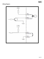
The 4-pin I/O terminal connector provides the interface to: 1 digital input, 1 digital output, auxiliary power and GND
(ground)
Some versions of the Y-cam Bullet may be supplied with the attached Digital I/O connector:
Pin
4
3
Function
GND
Digital Input
Description
Common Ground
Connect to GND to activate, or deactivate by software setting.
2
Digital Output
With a maximum load of 1A and maximum voltage of 60VDC, this output uses an opencollector NPN Darlington transistor with the emitter connected to the GND pin. If used
with an external relay a diode must be connected in parallel with the load for protection
against voltage transients.
1
Auxiliary DC Power
12V DC max. Electrically connected in parallel with the connector for the PS-L power
adapter, this pin provides an auxiliary connector for power to the unit. This pin can also
be used to power auxiliary equipment, max 40mA.
Page 46