1
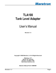
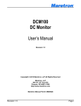
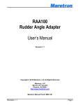
®
TLA100
Tank Level Adapter
User’s Manual
Revision 1.3
Copyright © 2012 Maretron, LLP All Rights Reserved
Maretron, LLP
9014 N. 23rd Ave #10
Phoenix, AZ 85021-7850
http://www.maretron.com
Maretron Manual Part #: M001001
Revision 1.3
Page i
TLA100 User’s Manual
Revision History
Revision
1.0
1.1
1.2
1.3
Page ii
Description
Original document
Minor Updates
Corrected default values of transmitted PGN’s
Clarified configuration options
Added cautions about using red Loctite and acetone cleaners
Added information on use of Type 2 (current source) analog gauges
Revision 1.3
®
Table of Contents
1 2 3 4 5 6 7 8 General ................................................................................................................................1 1.1 Introduction ....................................................................................................................1 1.2 Firmware Revision .........................................................................................................1 1.3 Features ........................................................................................................................1 1.4 Quick Install ...................................................................................................................2 Installation ............................................................................................................................2 2.1 Unpacking the Box.........................................................................................................2 2.2 Choosing a Mounting Location ......................................................................................2 2.2.1 Mounting Location When Used With Analog Gauge(s) .......................................2 2.2.2 Mounting Location When Used Without Analog Gauge(s) ..................................3 2.3 Connecting the TLA100 .................................................................................................4 2.3.1 Connecting Attached Gray Cable to Analog Gauge or Tank Sender ..................5 2.3.2 Connecting to NMEA 2000® Interface .................................................................6 Configuring the TLA100 .......................................................................................................6 3.1 Configuring Tank Type ..................................................................................................7 3.2 Configuring Tank Number ..............................................................................................7 3.3 Configuring Operating Mode ..........................................................................................7 3.3.1 Configuring Analog Gauge Resistance ...............................................................7 3.3.2 Configuring Type 2 (Current Source) Analog Gauges ........................................8 3.4 Configuring Tank Capacity ............................................................................................9 3.5 Standard Sender Selection or Custom Calibration ........................................................9 3.5.1 Standard Sender Selection .................................................................................9 3.5.2 Custom Calibration..............................................................................................9 Maintenance.........................................................................................................................9 Troubleshooting ................................................................................................................. 10 Technical Specifications .....................................................................................................11 Technical Support .............................................................................................................. 12 Maretron (2 Year) Limited Warranty ................................................................................... 13 Revision 1.3
Page iii
TLA100 User’s Manual
Table of Figures
Figure 1– Mounting Location When Used with Analog Gauge .................................................. 3
Figure 2 – Mounting Location When Used Without Analog Gauge ............................................ 4
Figure 3 – TLA100 Connections ................................................................................................ 4
Figure 4 – NMEA 2000® Connector Face Views ....................................................................... 6
Figure 5 – Troubleshooting Guide ........................................................................................... 11
List of Tables
Table 1 – TLA100 Gauge Connections ..................................................................................... 5
Table 2 – TLA100 Resistive Tank Sender Connections ............................................................ 5
Table of Appendices
Appendix A – NMEA 2000® Interfacing.................................................................................... A1
Page iv
Revision 1.3
®
1 General
1.1 Introduction
Congratulations on your purchase of the Maretron Tank Level Adapter (TLA100). Maretron has
designed and built your adapter to the highest standards for years of reliable, dependable, and
accurate service.
The TLA100 is used to adapt commercially available tank senders to the NMEA 2000®
network. This allows you to observe tank levels anywhere on the vessel where there is an
NMEA 2000® compatible display such as the Maretron DSM200, DSM250, or computer or
smartphone running Maretron’s N2KView software. The TLA100 is compatible with both the
American standard (240-33 ohm) and the European standard (10-180 ohm) resistive senders
and in fact, the TLA100 can be calibrated for any resistive sender with resistance values
between 0 and 300 ohms. Unlike most tank senders that only work with rectangular tanks, the
TLA100 can be calibrated for irregular tank shapes so you know the true level of your tanks.
You can also use the TLA100 with analog gauges so you don’t have to get rid of existing
gauges to enjoy the advantages of digitally networked information.
The Maretron TLA100 is designed to operate within the harsh demands of the marine
environment. However, no piece of marine electronic equipment can function properly unless
installed, calibrated, and maintained in the correct manner. Please read carefully and follow
these instructions for installation, calibration, and usage of the Maretron TLA100 in order to
ensure optimal performance.
1.2 Firmware Revision
This manual corresponds to TLA100 firmware revision 1.5.
1.3 Features
The Maretron TLA100 has the following features.
•
•
•
•
•
•
•
•
•
•
NMEA 2000® Interface
Adapts American standard (240-30 ohm) resistive senders to NMEA 2000® Network
Adapts European standard (10-180 ohm) resistive senders to NMEA 2000® Network
Can be Calibrated for any Resistive Sender Ranging from 0-300 Ohms or 300-0 Ohms
Accommodates Irregularly Shaped Tanks with 16 Point Calibration
16 Programmable Tank Types Including Fuel, Fresh Water, Waste Water, Live Well
Programmable Tank Number(s) Up to 16 per Tank Type
Programmable Tank Capacity
Works Alongside of Analog Gauges
Can be Used Standalone Without Analog Gauges
Revision 1.3
Page 1
TLA100 User’s Manual
1.4 Quick Install
Installing the Maretron TLA100 involves the following steps. Please refer to the individual
sections for additional details.
1.
2.
3.
4.
5.
6.
7.
8.
9.
Unpack the Box (Section 2.1)
Choose a Mounting Location (Section 2.2)
Connect the TLA100 (Section 2.3)
Configure or Program the Tank Type (Section 3.1)
Configure or Program the Tank Number (Section 3.2)
Configure or Program the Operating Mode (Section 3.3)
Configure or Program Tank Capacity (Section 3.4)
Configure or Program the Resistive Sender type: American or European (Section 3.5.1)
Optional – Custom Calibration (Section 3.5.2)
2 Installation
2.1 Unpacking the Box
When unpacking the box containing the Maretron TLA100, you should find the following items.
•
•
•
1 - TLA100 Tank Level Adapter
1 - TLA100 User’s Manual
1 - Warranty Registration Card
If any of these items are missing or damaged, please contact Maretron.
2.2 Choosing a Mounting Location
The primary function of the TLA100 is to adapt commercially available resistive tank senders to
an NMEA 2000® network so that tank level information can be viewed anywhere on the vessel
where there is an NMEA 2000® compatible display. The TLA100 can be used together with an
analog gauge(s) (referred to as NMEA 2000® / Analog Gauge Mode), or it can be used
standalone to power and sense the resistive sender without an analog gauge(s) (referred to as
NMEA 2000® Mode). If you are using the TLA100 with an analog gauge(s) then refer to
Section 2.2.1 for determining an appropriate mounting location and skip Section 2.2.2. If you
are using the TLA100 as a standalone adapter without attaching an analog gauge, then skip
Section 2.2.1 and refer to Section 2.2.2 for determining an appropriate mounting location. Do
not use threadlocking compounds containing methacrylate ester, such as Loctite Red (271), as
they will cause stress cracking of the plastic enclosure.
2.2.1 Mounting Location When Used With Analog Gauge(s)
The TLA100 has two primary connections: 1) the NMEA 2000® network connection, and 2) the
analog gauge connection. Therefore, the TLA100 should be located between the NMEA 2000®
trunk line and the analog gauge(s). The reason for choosing this location is because you will
be connecting some of the wires within the TLA100’s permanently attached gray cable to the
gauge and not the actual sender located at the tank. Maretron recommends placing the
TLA100 within 15 feet of the gauge so the TLA100’s permanently attached gray cable can be
Page 2
Revision 1.3
®
directly connected to the gauge without any splices (see Figure 1). You may also consider
placing the TLA100 as close as possible to the NMEA 2000® trunk line so you can purchase
the shortest or lowest cost NMEA 2000® drop cable. In fact, you can hook the TLA100 directly
to a tee attached to the NMEA 2000® trunk so you don’t have to purchase any drop cable. The
actual mounting of the TLA100 is not critical and the unit can be mounted in any orientation.
The TLA100, NMEA 2000® connector, and cable are all waterproof (rated IP67 – protected
against temporary immersion in water) so you can mount the unit virtually anywhere. Once you
have located a suitable mounting location, you can secure the TLA100 by placing wire ties with
screw eyes on the attached cables next to the TLA100.
Figure 1– Mounting Location When Used with Analog Gauge
2.2.2 Mounting Location When Used Without Analog Gauge(s)
The TLA100 has two primary connections: 1) the NMEA 2000® network connection, and 2) the
resistive tank sender connection. Therefore, the TLA100 should be located between the NMEA
2000® trunk line and the resistive tank sender. The reason for choosing this location is
because you will be connecting some of the wires within the TLA100’s permanently attached
gray cable to the tank sender. Maretron recommends placing the TLA100 within 15 feet of the
tank sender so the gray cable can be directly attached to the sender without any splices (see
Figure 2). You may also consider placing the TLA100 as close as possible to the NMEA 2000®
trunk line so you can purchase the shortest or lowest cost NMEA 2000® drop cable. In fact,
you can hook the TLA100 directly to a tee attached to the NMEA 2000® trunk so you don’t
have to purchase any drop cable. The actual mounting of the TLA100 is not critical and the unit
can be mounted in any orientation. The TLA100, NMEA 2000® connector, and cable are all
waterproof (rated IP67 – protected against temporary immersion in water) so you can mount
the unit virtually anywhere. Once you have located a suitable mounting location, you can
secure the TLA100 by placing wire ties with screw eyes on the attached cables near the
TLA100.
Revision 1.3
Page 3
TLA100 User’s Manual
Figure 2 – Mounting Location When Used Without Analog Gauge
2.3 Connecting the TLA100
There are two connection points (see Figure 3) for the TLA100: 1) the permanently attached
gray cable for connection to analog gauge or tank sender, and 2) the NMEA 2000® connection.
Refer to Section 2.3.1 for making the gauge or tank sender connection and Section 2.3.2 for
making NMEA 2000® connection.
Caution: Connect the TLA100’s permanently attached gray cable to the gauge or tank
sender before making the connection to the NMEA 2000® network as this reduces the
risk of a stray spark when working around fuel tanks.
NMEA 2000
Connector
Gray
Cable
Figure 3 – TLA100 Connections
Page 4
Revision 1.3
®
2.3.1 Connecting Attached Gray Cable to Analog Gauge or Tank Sender
The TLA100 can be used together with an analog gauge(s) (referred to as NMEA 2000® /
Analog Gauge Mode), or it can be used stand-alone (referred to as NMEA 2000® Mode) to
power and sense the resistive sender without an analog gauge(s). Connecting the TLA100’s
attached gray cable depends on how the TLA100 will be used. If you are using the TLA100
with an analog gauge(s) then refer to Section 2.3.1.1 and skip Section 2.3.1.2. If you are using
the TLA100 as a stand-alone adapter without attaching an analog gauge, then skip Section
2.3.1.1 and refer to Section 2.3.1.2.
2.3.1.1 Connecting Attached Gray Cable to Analog Gauge
Connecting the TLA100’s permanently attached gray cable to the analog gauge does not
require the removal of any wires between the gauge and the tank. All connections normally
made between the gauge and tank stay in place and the TLA100 is simply connected to the
terminals on the back of the gauge. Not including the gauge light connections, analog gauges
have three connection points or terminals: 1) power, 2) ground, and 3) sensor. The power
connection may be marked with a plus sign “+”,“+12V”, or an “I” or “IGN”, while the ground
connection is usually marked with a minus sign “-“, the earth ground symbol “ ”, or a “G” for
ground, and the sensor connection is generally marked with an “S” for sensor or “G” for gauge.
You might have to refer to the gauge documentation or schematic to determine the exact
function of the three gauge terminals but it is important to distinguish which terminals are the
power, ground, and sensor. Once you have determined the terminals on the back of the
gauge, connect the wires found within the TLA100’s permanently attached gray cable as
shown in Table 1 using recommended wiring practices (i.e., ABYC, Coast Guard, NMEA, ISO,
etc.).
Gauge Terminals
Power (+, +12V, I, IGN)
Ground (-, , G)
Sensor (S, G)
Wire Color
Red
Black
Green
Table 1 – TLA100 Gauge Connections
2.3.1.2 Connecting Attached Gray Cable to Tank Sender
Resistive tank senders have two terminals; 1) sensor terminal and 2) ground terminal. The
sensor terminal is usually marked with an “S” for sensor or a “G” for gauge where the ground
terminal is usually marked with a minus sign “-“. A good way to determine which terminal is the
ground is to observe which terminal is touching the metal housing; this will be the ground
terminal. The sensor terminal will be insulated from the metal housing. Once you have
determined the terminals on the resistive tank sender, connect the wires found within the
TLA100’s permanently attached gray cable as shown in Table 2 using recommended wiring
practices (i.e., ABYC, Coast Guard, NMEA, ISO, etc.).
Sender Terminals
Sensor (S, G)
Ground (-)
Wire Color
White
Black
Table 2 – TLA100 Resistive Tank Sender Connections
Revision 1.3
Page 5
TLA100 User’s Manual
2.3.2 Connecting to NMEA 2000® Interface
The Maretron TLA100 provides a connection to an NMEA 2000® interface through a five pin
male connector (see Figure 4). You connect the TLA100 to an NMEA 2000® network using a
Maretron NMEA 2000® cable (or an NMEA 2000® compatible cable) by connecting the female
end of the cable to the TLA100 (note the key on the male connector and keyway on the female
connector). Be sure the cable is connected securely and that the collar on the cable connector
is tightened firmly. Connect the other end of the cable (male) to the NMEA 2000® network in
the same manner. The TLA100 is designed such that you can plug or unplug it from an NMEA
2000® network while the power to the network is connected or disconnected. Please follow
recommended practices for installing NMEA 2000® network products.
Figure 4 – NMEA 2000® Connector Face Views
3 Configuring the TLA100
The TLA100 has several configurable parameters, which are shown below including the
default values. If you are not using the default values, then you will need to refer to the
corresponding section for configuring the TLA100 appropriately.
1.
2.
3.
4.
5.
Tank Type – Default is Fuel (Section 3.1)
Tank Number – Default is Tank 0 (Section 3.2)
Operating Mode – Default is NMEA 2000® Mode (Section 3.3)
Tank Capacity – Default is No Tank Capacity Transmitted (Section 3.4)
Resistive Sender – Default is American standard (Section 3.5)
In addition to configurable parameters, the TLA100 can be calibrated for standard resistive
senders (i.e., American standard 240-30 ohm, European standard 10-180 ohms), the TLA100
can be calibrated for non-standard resistive senders (i.e., any resistance between 0 and 300 or
300 and 0 ohms), or the TLA100 can be custom calibrated for any shape tank. Refer to
Section 3.5 for choosing a standard type resistive sender or custom calibrating the TLA100.
Page 6
Revision 1.3
®
3.1 Configuring Tank Type
As shipped from the factory, the TLA100 transmits the tank type as “Fuel. You can reconfigure
the TLA100 for any of these tank types:
1.
2.
3.
4.
5.
6.
Fuel
Fresh Water
Waste Water
Live Well
Oil
Black Water
3.2 Configuring Tank Number
As shipped from the factory, the TLA100 transmits the Tank Number as “0”. The TLA100
supports up to sixteen tanks (0 through 15) for a given type of tank, which means you can
monitor up to 16 separate fuel tanks or 16 separate fresh water tanks. The TLA100 is
configured or programmed by choosing a TLA100 tank number using a display product such
as the Maretron DSM200, DSM250, or Maretron’s N2KAnalyzer software. Refer to the user’s
manual of the display or software for configuring the TLA100 as the manual provides detailed
instruction on configuration procedures.
3.3 Configuring Operating Mode
The TLA100 operates in one of three modes: 1) NMEA 2000® Mode, or 2) NMEA 2000® /
Analog Gauge Mode, or NMEA 2000®/Type 2 Analog Gauge Mode. You configure or place the
TLA100 into NMEA 2000® Mode when you are connecting the TLA100 directly to the resistive
tank sender (see Figure 2) and you are not using an analog gauge. In NMEA 2000® Mode, the
TLA100 supplies an electrical current to the resistive tank sender and monitors the changing
voltage as the tank is filled or emptied. Whenever the TLA100 is used together with an analog
dual-coil gauge, then you configure or place the TLA100 into NMEA 2000® / Analog Gauge
Mode. In this mode, the analog gauge supplies the electrical current to the resistive tank
sender while the TLA100 monitors the changing voltage. Placing the TLA100 into NMEA
2000® / Analog Gauge Mode requires you to configure or program the TLA100 with the analog
gauge’s resistances, which are described in Section 3.3.1. Whenever the TLA is used together
with an analog current-source gauge (such as some Faria gauges), then you configure of
place the TLA100 into NMEA 2000® / Type 2 Analog Gauge Mode. Placing the TLA100 into
NMEA 2000® / Type 2 Analog Gauge Mode requires you to configure or program the TLA100
with the amount of current sourced buy the gauge, which is described in Section ??. You can
configure or program a TLA100 operating mode through a display product such as the
Maretron DSM200 or DSM250, or Maretron N2KAnalyzer software. Refer to the user’s manual
for configuring the TLA100 as the manual provides detailed instruction on configuration
procedures.
3.3.1 Configuring Analog Gauge Resistance
If you are using the TLA100 in the NMEA 2000® / Analog Gauge Mode, then two different
analog gauge resistances need to be measured and programmed into the TLA100. You will
Revision 1.3
Page 7
TLA100 User’s Manual
need an ohmmeter to make the two resistive measurements, which are 1) power terminal to
sensor terminal resistance measurement (see Section 3.3.1.1), and 2) ground terminal to
sensor terminal resistance measurement (see Section 3.3.1.2). Once you have made these
measurements, you can enter the TLA100 gauge resistances through a display product such
as the Maretron DSM200. Refer to the user’s manual for configuring the TLA100 as the
manual provides detailed instruction on configuration procedures.
3.3.1.1 Power Terminal to Sensor Terminal Resistance Measurement
The first resistance measurement is between the power terminal and the sensor terminal found
on the back of the gauge. Before making the measurement, disconnect the power, ground, and
sensor wires from the gauge. Then, measure and record the resistance between the power
terminal and the sensor terminal (see Section 2.3.1.1 for help in determining which terminal is
which). Make sure to adjust the ohmmeter scale to give you whole numbers without over
ranging (sometimes indicated by blinking display or a 1 in the far left hand digit position). If you
see only numbers right of the decimal point, keep adjusting the scale down (usually the highest
ohm scale is indicated by a capital M for mega-ohms or 106 ohms while the next lower scale is
indicated with a capital K for kilo-ohms or 103 ohms). Typical resistance values between the
power terminal and the sensor terminal are between 100 and 200 ohms so you should be able
to use the 200-ohm scale.
3.3.1.2 Ground Terminal to Sensor Terminal Resistance Measurement
The second resistance measurement is between the ground terminal and the sensor terminal
found on the back of the gauge. Before making the measurement, disconnect the power,
ground, and sensor wires from the gauge. Then, measure and record the resistance between
the ground terminal and the sensor terminal (see Section 2.3.1.1 for help in determining which
terminal is which). Typical resistance values between the ground terminal and the sensor
terminal are between 100 and 400 ohms, however, some gauges have very high resistance
(i.e., greater than 1000 ohms). A resistance value over 1000 ohms generally indicates a low
cost, low accuracy gauge (i.e., gauge reading changes with battery voltage even though fluid
level is not changing). If the resistance measurement is above 1000 ohms, don’t worry about
recording the exact reading, as the maximum programmable value in the TLA100 is 3000
ohms. Maretron recommends that you custom calibrate (see Section 3.5.2) your system
whenever you are using a gauge with a reading of 3000 ohms or more. Also, you must be
aware that these inexpensive gauges won’t necessarily agree with the digital data available on
the NMEA 2000® network as the gauges tend to be inaccurate.
3.3.2 Configuring Type 2 (Current Source) Analog Gauges
These gauges generally have a positive (supply voltage connection and a sender connection).
To make this measurement, supply power to the gauge and then connect an ammeter
between the sender terminal of the gauge and ground (this current may be in the tens or
hundreds of milliamperes, so be sure and set the ammeter to the correct current range). The
amount of current indicated on the ammeter is the value of the current source that should be
programmed into the TLA100.
Page 8
Revision 1.3
®
3.4 Configuring Tank Capacity
In addition to indicating the fluid level within a tank, the TLA100 also has the ability to be
configured or programmed with the attached tank’s capacity. This way, you will be able to view
the tank’s capacity as well as the amount of fuel remaining anywhere on the vessel where
there is an NMEA 2000® compatible display. It is not required, but you can enter the TLA100
tank capacity using a display product such as the Maretron DSM200. Refer to the user’s
manual for configuring the TLA100 as the manual provides detailed instruction on configuration
procedures.
3.5 Standard Sender Selection or Custom Calibration
The TLA100 is capable of accepting standard resistive values (see Section 3.5.1) or it can be
calibrated for any resistance range between 0 and 300 or 300 and 0 ohms using the custom
calibration procedure (see Section 3.5.2). In addition, the TLA100 can be calibrated for nonrectangular tank shapes for any resistive tank sender having resistance values from 0 to 300
ohms (see Section 3.5.2).
3.5.1 Standard Sender Selection
The TLA100 can be used with standard resistive tank senders such as the American Standard
(240-30 ohms) or the European Standard (10-180 ohms). You can select which type of sender
is attached to the TLA100 using a display product such as the Maretron DSM200. Refer to the
user’s manual for configuring the TLA100 as the manual provides detailed instruction on
configuration procedures.
3.5.2 Custom Calibration
The TLA100 can be custom calibrated for one of several reasons:
1. A non-standard resistive tank sender is being used,
2. A standard resistive tank sender is used, but maximum accuracy is desired,
3. The tank shape is irregular or non-rectangular.
Regardless of the reason for custom calibrating the TLA100, you can calibrate the TLA100
using a display product such as the Maretron DSM200. Refer to the user’s manual of the
particular product that will be used for configuring the TLA100 as these manuals provide
detailed instruction on configuration procedures.
4 Maintenance
Regular maintenance is not required, however, an occasional inspection will ensure continued
proper operation of the Maretron TLA100. Perform the following tasks periodically:
•
•
Clean the unit with a soft cloth. Do not use chemical cleaners as they may remove
paint or markings or may corrode the DCR100 enclosure or seals. Do not use any
cleaners containing acetone, as they will deteriorate the plastic enclosure.
Ensure that the unit is mounted securely and cannot be moved relative to the mounting
surface. If the unit is loose, tighten the screws holding the cable ties.
Revision 1.3
Page 9
TLA100 User’s Manual
•
Check the security of the cables connected to the NMEA 2000® interface and the
connections to the gauge or sender and tighten if necessary.
5 Troubleshooting
If you notice unexpected operation of the Maretron TLA100, follow the troubleshooting
procedures in this section to remedy simple problems.
Symptom
No tank level
output
Inaccurate tank
level output
Page 10
Troubleshooting Procedure
1. If operating in the NMEA 2000® Mode, check the connections to the
NMEA 2000® interface (see Section 2.3.2) and/or the connection to the
resistive tank sender (see Section 2.3.1.2) and tighten if necessary.
2. If operating in the NMEA 2000® / Analog Gauge Mode, then check the
connections to the NMEA 2000® interface (see Section 2.3.2) and/or
the connection to the analog gauge (see Section 2.3.1.1) and tighten if
necessary.
3. Ensure that power is supplied to the NMEA 2000® network. Proper
network power can be checked by measuring the voltage at an open
tee between NET-S and NET-C. The voltage should be between 9 and
16 volts.
4. Ensure that both trunk line terminators are in place. Proper network
termination can be checked by removing network power and
measuring the resistance at an open tee between NET-L and NET-H
signals. The resistance should read approximately 60 ohms (two 120
ohm terminators in parallel equals 60 ohms).
1. Remember, the accuracy of most analog gauges/resistive tank
senders is at best plus or minus 10%. The inaccuracies are due to
both the analog gauge and the resistive tank senders. Although the
TLA100 is a precision instrument, it is only as good as the resistive
sender, which may not be as accurate as you like. Avoid low cost
resistive tank senders if you desire good accuracy.
2. If using a standard resistive tank sender (American standard 240-30
ohm, European standard 10-180 ohms), make sure you have correctly
configured the TLA100 for the appropriate standard (see Section
3.5.1).
3. If using a standard resistive tank sender (i.e., American or European),
you may want to consider custom calibration (see Section 3.5.2). The
standard sensor values assume that your tank is empty when the float
is bottomed out (i.e., one end of the resistive range) and that the tank
is full when the float is all the way up (i.e., the other end of the resistive
range), which may not be the case if, for example, the tank drain is
above the bottom of the tank. Custom calibration will use actual
minimum and maximum resistive values instead of assuming that the
tank is full and empty at the standard resistive extremes.
4. If using custom calibration, re-calibrate the TLA100 (see Section
3.5.2).
5. If operating in the NMEA 2000® / Analog Gauge Mode, ensure correct
Revision 1.3
®
Symptom
Troubleshooting Procedure
analog gauge resistive values have been configured or programmed
into the TLA100 (see Section 3.3.1)
Figure 5 – Troubleshooting Guide
If these steps do not solve your problem, please contact Maretron Technical Support (refer to
Section 7 for contact information).
6 Technical Specifications
Specifications
Parameter
Accuracy
Resolution
Number of Tank Types
Number of Tanks per Tank Type
American Standard Senders
European Standard Senders
Calibration Resistance Range
Support for Irregularly Shaped
Tanks
Programmable Tank Capacity
Analog Gauge Support
Value
+/-2%
+/-1%
254
16
240-30 ohms
10-180 ohms
0-300 ohms
Yes
Yes
Yes
Comment
Does Not Include Inaccuracies of Analog Gauge or Sender
Worst Case (Resolution Better at High Resistance Values)
Fuel, Fresh Water, Waste Water, Live Well, Oil, etc.
16 Tanks per Tank Type Numbered 0-15
Standard Sender Types are User Selectable
Standard Sender Types are User Selectable
Non-Standard Sender Calibration
Can be Calibrated for any Shape Tank
Allows Displays to Calculate Amount Remaining
Can be Used With or Without Analog Gauges
Certifications
Parameter
NMEA 2000
Maritime Navigation and Radiocommunication Equipment & Systems
FCC and CE Mark
Comment
Level B+
Tested to IEC 60945
Electromagnetic Compatibility
NMEA 2000® Parameter Group Numbers (PGNs) - See Appendix A for Details
Description
Periodic Data PGNs
Response to Requested PGNs
Protocol PGNs
PGN #
127250
126464
126996
126998
059392
059904
060928
065240
126206
PGN Name
Fluid Level
PGN List (Transmit and Receive)
Product Information
Configuration Information
ISO Acknowledge
ISO Request
ISO Address Claim
ISO Address Command
NMEA
Default Rate
0.4 Times/Second
N/A
N/A
N/A
N/A
N/A
N/A
N/A
N/A
Electrical
Parameter
Operating Voltage
Power Consumption
Load Equivalence Number (LEN)
Reverse Battery Protection
Load Dump Protection
Revision 1.3
Value
9 to 16 Volts
<100mA
2
Yes
Yes
Comment
DC Voltage
Average Current Drain
NMEA 2000® Spec. (1LEN = 50mA)
Indefinitely
Energy Rated per SAE J1113
Page 11
TLA100 User’s Manual
Mechanical
Parameter
Value
3.9”” x 1.2” x 1.0”
9 oz.
Any Orientation
Size
Weight
Mounting
Comment
Excluding NMEA 2000® Connector & Cable
Environmental
Parameter
IEC 60954 Classification
Degree of Protection
Operating Temperature
Storage Temperature
Relative Humidity
Vibration
Rain and Spray
Solar Radiation
Corrosion (Salt Mist)
Electromagnet Emission
Electromagnetic Immunity
Safety Precautions
Value
Exposed
IP67
-25°C to 55°C
-40°C to 70°C
93%RH @40° per IEC60945-8.2
2-13.2Hz @ ±1mm, 13.2-100Hz @ 7m/s2 per IEC 60945-8.7
12.5mm Nozzle @ 100liters/min from 3m for 30min per IEC 60945-8.8
Ultraviolet B, A, Visible, and Infrared per IEC 60945-8.10
4 times 7days @ 40°C, 95%RH after 2 hour Salt Spray Per IEC 60945-8.12
Conducted and Radiated Emission per IEC 60945-9
Conducted, Radiated, Supply, and ESD per IEC 60945-10
Dangerous Voltage, Electromagnetic Radio Frequency per IEC 60945-12
7 Technical Support
If you require technical support for Maretron products, you can reach us in one of the following
ways:
Telephone: 1-866-550-9100
Fax: 1-602-861-1777
E-mail: [email protected]
World Wide Web: http://www.maretron.com
Mail: Maretron, LLC
Attn: Technical Support
9034 N. 23rd Ave Suite 13
Phoenix, AZ 85021 USA
Page 12
Revision 1.3
®
8
Maretron (2 Year) Limited Warranty
Maretron warrants the TLA100 to be free from defects in materials and workmanship for two (2) years from the
date of original purchase. If within the applicable period any such products shall be proved to Maretron’s
satisfaction to fail to meet the above limited warranty, such products shall be repaired or replaced at Maretron’s
option. Purchaser's exclusive remedy and Maretron’s sole obligation hereunder, provided product is returned
pursuant to the return requirements below, shall be limited to the repair or replacement, at Maretron’s option, of
any product not meeting the above limited warranty and which is returned to Maretron; or if Maretron is unable to
deliver a replacement that is free from defects in materials or workmanship, Purchaser’s payment for such
product will be refunded. Maretron assumes no liability whatsoever for expenses of removing any defective
product or part or for installing the repaired product or part or a replacement therefore or for any loss or damage
to equipment in connection with which Maretron’s products or parts shall be used. With respect to products not
manufactured by Maretron, Maretron’s warranty obligation shall in all respects conform to and be limited to the
warranty actually extended to Maretron by its supplier. The foregoing warranties shall not apply with respect to
products subjected to negligence, misuse, misapplication, accident, damages by circumstances beyond
Maretron’s control, to improper installation, operation, maintenance, or storage, or to other than normal use or
service.
THE FOREGOING WARRANTIES ARE EXPRESSLY IN LIEU OF AND EXCLUDES ALL OTHER EXPRESS OR
IMPLIED WARRANTIES, INCLUDING BUT NOT LIMITED TO THE IMPLIED WARRANTIES OF
MERCHANTABILITY AND OF FITNESS FOR A PARTICULAR PURPOSE.
Statements made by any person, including representatives of Maretron, which are inconsistent or in conflict with
the terms of this Limited Warranty, shall not be binding upon Maretron unless reduced to writing and approved by
an officer of Maretron.
IN NO CASE WILL MARETRON BE LIABLE FOR INCIDENTAL OR CONSEQUENTIAL DAMAGES, DAMAGES
FOR LOSS OF USE, LOSS OF ANTICIPATED PROFITS OR SAVINGS, OR ANY OTHER LOSS INCURRED
BECAUSE OF INTERRUPTION OF SERVICE. IN NO EVENT SHALL MARETRON’S AGGREGATE LIABILITY
EXCEED THE PURCHASE PRICE OF THE PRODUCT(S) INVOLVED. MARETRON SHALL NOT BE SUBJECT
TO ANY OTHER OBLIGATIONS OR LIABILITIES, WHETHER ARISING OUT OF BREACH OF CONTRACT OR
WARRANTY, TORT (INCLUDING NEGLIGENCE), OR OTHER THEORIES OF LAW WITH RESPECT TO
PRODUCTS SOLD OR SERVICES RENDERED BY MARETRON, OR ANY UNDERTAKINGS, ACTS OR
OMISSIONS RELATING THERETO.
Maretron does not warrant that the functions contained in any software programs or products will meet
purchaser’s requirements or that the operation of the software programs or products will be uninterrupted or error
free. Purchaser assumes responsibility for the selection of the software programs or products to achieve the
intended results, and for the installation, use and results obtained from said programs or products. No
specifications, samples, descriptions, or illustrations provided Maretron to Purchaser, whether directly, in trade
literature, brochures or other documentation shall be construed as warranties of any kind, and any failure to conform
with such specifications, samples, descriptions, or illustrations shall not constitute any breach of Maretron’s limited
warranty.
Warranty Return Procedure:
To apply for warranty claims, contact Maretron or one of its dealers to describe the problem and determine the
appropriate course of action. If a return is necessary, place the product in its original packaging together with
proof of purchase and send to an Authorized Maretron Service Location. You are responsible for all shipping and
insurance charges. Maretron will return the replaced or repaired product with all shipping and handling prepaid
except for requests requiring expedited shipping (i.e. overnight shipments). Failure to follow this warranty return
procedure could result in the product’s warranty becoming null and void.
Maretron reserves the right to modify or replace, at its sole discretion, without prior notification, the warranty listed
above. To obtain a copy of the then current warranty policy, please go to the following web page:
http://www.maretron.com/company/warranty.php
Revision 1.3
Page 13
TLA100 User’s Manual
This page intentionally left blank.
Page 14
Revision 1.3
®
Appendix A – NMEA 2000® Interfacing
TLA100 NMEA 2000® Periodic Data Transmitted PGNs
PGN 127505 – Fluid Level
The TLA100 uses this PGN to indicate the attached tank’s fluid instance, fluid type, fluid level,
and tank capacity.
Field 1: Fluid Instance – This field is used to identify the tank number and ranges between 0
and 15. There can be up to 16 tanks of a given type as defined by the Fluid Type
field. This field is programmable through the NMEA command PGN. The TLA100
ships from the factory with a default value of zero.
2: Fluid Type – This field identifies the type of fluid contained within the tank. Currently
the defined fluid types are fuel, fresh water, wastewater, live well, oil, and black
water. The TLA100 ships from the factory with a default value of 0x0 indicating
“Fuel”.
3: Fluid Level – This field is used to indicate the current fluid level in percentage. The
value transmitted in this field depends on the sender resistance value..
4: Tank Capacity – This field is used to indicate the tank capacity. The TLA100 ships
from the factory with a default value of 0xFFFFFFFF indicating “Data Not Available”.
5: Reserved – This field is reserved by NMEA; therefore, the TLA100 sets all bits to a
logic 1.
Revision 1.3
Appendix A – NMEA 2000® Interfacing
Page A1