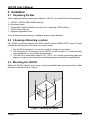
1
®
J2K100
J1939 to NMEA 2000® Gateway
User’s Manual
Revision 1.2
Warning: Improper installation of the Maretron J2K100 may prevent existing engine
accessories (i.e., engine gauge displays, key switches, throttle and shift controls, etc.) from
working properly. You must have an understanding of J1939 data networks before attempting
to install the J2K100. Maretron strongly recommends that you understand SAE documents
J1939-11 and J1939-15 (see Section 3.1 of Appendix B) before attempting to install the
J2K100 and that you consult the engine/genset manufacture for their recommendations before
connecting anything to the J1939 network.
Copyright © 2009 Maretron, LLP All Rights Reserved
Maretron, LLP
9014 N. 23rd Ave #10
Phoenix, AZ 85021-7850
http://www.maretron.com
Maretron Manual Part #: M001201
Revision 1.2
Page i
J2K100 User’s Manual
Revision History
Revision
Description
1.0
Original document
1.1
Changed address on cover page
Added warning on cover page
Miscellaneous editorial changes
Added Appendix B
1.2
Changed cable part numbers in Appendix B to reflect new Maretron part #’s
Inserted new figure showing J1939 connection diagram
Added new translations to Section 5 (Technical Specifications)
Updated Mounting Drawings and Mounting Template for new (black) enclosure
Page ii
Revision 1.2
®
Table of Contents
1 Introduction ............................................................................................................................1
1.1 Firmware Revision .................................................................................................... 1
1.2 J2K100 Features ...................................................................................................... 1
1.3 Quick Install .............................................................................................................. 1
2 Installation ..............................................................................................................................2
2.1 Unpacking the Box ................................................................................................... 2
2.2 Choosing a Mounting Location ................................................................................. 2
2.3 Mounting the J2K100................................................................................................ 2
2.4 Connecting the J2K100 ............................................................................................ 3
2.4.1 Connecting the J2K100 NMEA 2000® Interface............................................. 3
2.4.2 Connecting the J2K100 J1939 Interface ........................................................ 4
2.4.3 Checking Connections ................................................................................... 5
2.5 Configuring the J2K100 ............................................................................................ 5
2.5.1 J1939 Source Address Selection ................................................................... 5
2.5.2 NMEA 2000® Engine Instance Selection ....................................................... 5
2.5.3 NMEA 2000® Transmission Instance Selection ............................................. 6
2.5.4 J1939 Diagnostic Messages Enable/Disable ................................................. 6
2.5.5 NMEA 2000® PGN Enable/Disable ................................................................ 6
3 Maintenance ...........................................................................................................................7
4 Troubleshooting......................................................................................................................7
5 Technical Specifications .........................................................................................................8
6 Technical Support ................................................................................................................ 10
7 Installation Template ............................................................................................................ 11
8 Maretron (2 Year) Limited Warranty ..................................................................................... 12
Table of Figures
Figure 1 – Mounting the J2K100 ................................................................................................ 2
Figure 3 – J2K100 Electrical Connections ................................................................................. 3
Figure 4 – NMEA 2000® Connector Face Views ....................................................................... 4
Figure 6 – Mounting Surface Template ................................................................................... 11
Table of Appendices
Appendix A – NMEA 2000® Interfacing Translations ............................................................... A1
Appendix B – Application Note ................................................................................................ B1
Revision 1.2
Page iii
J2K100 User’s Manual
This Page Intentionally Left Blank
Page iv
Revision 1.2
®
1 Introduction
Congratulations on your purchase of the Maretron J1939 to NMEA 2000® Gateway (J2K100).
Maretron has designed and built your gateway to the highest standards for years of
dependable and accurate service.
Maretron’s J2K100 is a gateway for bridging J1939-equipped engines and gensets with an
NMEA 2000® network. The gateway automatically converts incoming J1939 messages to
NMEA 2000® messages so you can monitor your J1939-equipped engines, transmissions, or
gensets with networked NMEA 2000® displays such as the Maretron DSM200 or DSM250.
The Maretron J2K100 is designed to operate within the harsh demands of the marine
environment. However, no piece of marine electronic equipment can function properly unless
installed, configured, and maintained in the correct manner. Please read carefully and follow
these instructions for installation, configuration, and usage of the Maretron J2K100 in order to
ensure optimal performance.
1.1 Firmware Revision
This manual corresponds to J2K100 firmware revision 1.0.8.
1.2 J2K100 Features
The Maretron J2K100 has the following features.
•
•
•
•
•
•
•
•
NMEA 2000® and J1939 Interfaces
Waterproof Connectors
Sealed Waterproof Enclosure
Translates J1939 Engine and Transmission Messages to Equivalent NMEA 2000®
Messages
Capable of Passing J1939 Diagnostic Messages
Passes J1939 AC Generator Parameters through to the NMEA 2000® network
J1939 Interface is Opto-Isolated from NMEA 2000® Eliminating Potential Ground Loops
Obtains Power from NMEA 2000® Port (No power drawn from or data transmitted on
J1939 interface).
1.3 Quick Install
Installing the Maretron J2K100 gateway involves the following five steps. Please refer to the
individual sections for additional details.
1.
2.
3.
4.
5.
Unpack the Box (Section 2.1)
Choose a Mounting Location (Section 2.2)
Mount the J2K100 (Section 2.3)
Connect the J2K100 (Section 2.4)
Configure the J2K100 - Optional, only required for specialized configurations (Section 2.5)
Revision 1.2
Page 1
J2K100 User’s Manual
2 Installation
2.1 Unpacking the Box
When unpacking the box containing the Maretron J2K100, you should find the following items:
1 – J2K100 - J1939 to NMEA 2000® Gateway
4 – Mounting Screws
1 – Female Micro Field-Attachable Connector (For connecting J1939 interface)
1 – J2K100 User’s Manual
1 – Warranty Registration Card
If any of these items are missing or damaged, please contact Maretron.
2.2 Choosing a Mounting Location
The J2K100 is mounted between the J1939 network and the NMEA 2000® network. Please
consider the following when choosing a mounting location.
1. The J2K100 is waterproof, so it can be mounted in a damp or dry location.
2. The orientation is not important, so the J2K100 can be mounted on a horizontal deck,
vertical bulkhead, or even upside down if desired.
3. The J2K100 is temperature rated to 55°C (130°F), so it should be mounted away from
engines or engine rooms where the operating temperature exceeds the specified limit.
2.3 Mounting the J2K100
Attach the J2K100 securely to the vessel using the included brass mounting screws or other
fasteners as shown in Figure 1 below.
Figure 1 – Mounting the J2K100
Page 2
Revision 1.2
®
2.4 Connecting the J2K100
The J2K100 requires two electrical connections as shown in Figure 2. Refer to Section 2.4.1
for making the NMEA 2000® connection and Section 2.4.2 for making the J1939 connection.
Additional information can be found in Appendix B - Interfacing J1939 Engines and/or Gensets
to an NMEA 2000® Network Using Maretron’s J1939 to NMEA 2000® Gateway (J2K100).
NMEA 2000
NMEA 2000
®
®
connector
port
J1939 Port
J1939 Field Attachable Connector (Female)
Figure 2 – J2K100 Electrical Connections
2.4.1 Connecting the J2K100 NMEA 2000® Interface
Vertical text on the J2K100 label identifies the NMEA 2000® connector. With the label right
side up, the NMEA 2000® connector can be found on the right side of the enclosure. The
NMEA 2000® connector is a five pin male connector (see Figure 3). You connect the J2K100
to an NMEA 2000® network using a Maretron NMEA 2000® cable (or compatible cable) by
connecting the female end of the cable to the J2K100 (note the key on the male connector and
keyway on the female connector). Be sure the cable is connected securely and that the collar
on the cable connector is tightened firmly. Connect the other end of the cable (male) to the
NMEA 2000® network in the same manner. The J2K100 is designed such that you can plug or
unplug it from an NMEA 2000® network while the power to the network is connected or
disconnected. Please follow recommended practices for installing NMEA 2000® network
products. See Figure 3 for NMEA 2000® connector pin assignments.
Revision 1.2
Page 3
J2K100 User’s Manual
Figure 3 – NMEA 2000® Connector Face Views
2.4.2 Connecting the J2K100 J1939 Interface
Vertical text on the J2K100 label identifies the J1939 connector. With the label right side up,
the J1939 connector can be found on the left side of the enclosure. In order to make the J1939
connection, you will need to locate the supplied female field attachable connector. This
connector is fitted to one end of a 3-conductor cable (not supplied). Make the connections
between the 3-conductor cable and the field attachable connector by following the instruction
contained within the bag. Although the field attachable connector has 5 terminals, you only
need to connect the CAN bus signals and ground signal (NET-H, white terminal; NET-L, blue
terminal; and ground (or NET-C), black terminal). The other end of the 3-conductor cable
needs to be tied into the J1939 network. You will need to identify the CAN bus signals on the
J1939 network by reviewing the manufacturer’s documentation. Most likely, they will identify
the CAN bus signals as CAN-H and CAN-L which correspond to the field attachable terminals
NET-H and NET-L respectively. You will also need to connect the NET-C or ground signal
found within the field attachable connector to the J1939 ground connection. See Figure 4 for
J1939 connector pin assignments
Page 4
Revision 1.2
®
Pin 1: No Connection
Pin 2: No Connection
Pin 3: J1939 Ground
Pin 4: NET-H, CAN-H
Pin 5: NET-L, CAN-L
Figure 4 – J1939 Connector Face Views
2.4.3 Checking Connections
Once the NMEA 2000® and J1939 connections to the J2K100 have been completed, check to
see that information is being properly transmitted by observing an appropriate NMEA 2000®
display. If you don’t see engine and/or generator data, refer to Section 4, “Troubleshooting”.
2.5 Configuring the J2K100
As shipped from the factory, the J2K100 does not require any special configuration and will
work for most applications. However, there are several configurable items within the J2K100,
including: 1) J1939 source address selection, 2) NMEA 2000® engine instance selection, 3)
NMEA 2000® transmission instance selection, 4) J1939 diagnostic messages enable/disable,
and 4) NMEA 2000® PGN enable/disable.
2.5.1 J1939 Source Address Selection
The J2K100 connects into a J1939 network and translates messages from a single J1939
device into NMEA 2000® messages. By default, the J2K100 only translates J1939 messages
from a J1939 device with a source address of zero. If the J1939 source address of the engine,
transmission, or genset to be monitored is different than zero, then the J2K100 must be
programmed with the appropriate J1939 source address. This can be done with the Maretron
DSM200 or DSM 250 displays or other NMEA 2000® display unit that is capable of configuring
the J2K100. Plese refer to the Maretron DSM200 User’s Manual or DSM250 User’s Manual, as
appropriate, for details.
2.5.2 NMEA 2000® Engine Instance Selection
NMEA 2000® provides a unique engine instance for each engine on a vessel. Single engine
vessels use engine instance zero (0) while dual engine vessels use engine instance zero (0)
Revision 1.2
Page 5
J2K100 User’s Manual
for the port engine and engine instance one (1) for the starboard engine. By default, the
J2K100 uses engine instance zero (0). If you are installing the J2K100 on a single engine
vessel, then you don’t have to configure this parameter. However, if you install two J2K100s
for dual engine vessels, then you will need to configure the starboard engine J2K100 to use
engine instance one (1). You configure the J2K100 using a Maretron DSM200 or DSM250
display or other NMEA 2000® display unit that is capable of configuring the J2K100. Please
refer to the Maretron DSM200 User’s Manual or DSM250 User’s Manual, as appropriate, for
details.
2.5.3 NMEA 2000® Transmission Instance Selection
NMEA 2000® provides a unique transmission instance for each transmission on a vessel.
Single transmission vessels use transmission instance zero (0) while dual transmission
vessels use transmission instance zero (0) for the port transmission and transmission instance
one (1) for the starboard transmission. By default the J2K100 uses transmission instance zero
(0). If you are installing the J2K100 on a single transmission vessel, then you don’t have to
configure this parameter. However, if you install two J2K100s for dual transmission vessels,
then you will need to configure the starboard transmission J2K100 to use transmission
instance one (1). You configure the J2K100 using a Maretron DSM200 or DSM250 display or
other NMEA 2000® display unit that is capable of configuring the J2K100. Please refer to the
Maretron DSM200 User’s Manual or DSM250 User’s Manual, as appropriate, for details.
2.5.4 J1939 Diagnostic Messages Enable/Disable
The J2K100 is capable of re-broadcasting J1939 diagnostic messages output by the monitored
engine, transmission, or genset onto the NMEA 2000® network. As shipped from the factory,
the J2K100 does not transmit J1939 diagnostic messages over the NMEA 2000® network. If
this behavior is desired, it may be enabled with the Maretron DSM200 or DSM250 display or
other NMEA 2000® display unit that is capable of configuring the J2K100. Please refer to the
Maretron DSM200 User’s Manual or DSM250 User’s Manual, as appropriate, for details.
2.5.5 NMEA 2000® PGN Enable/Disable
The J2K100 is capable of transmitting several different kinds of NMEA 2000® messages (or
PGNs) associated with engines, transmissions, and gensets. The J2K100 automatically
detects incoming messages from the J1939 network and translates them into corresponding
NMEA 2000® PGNs. For example, if the J2K100 receives engine-related messages from the
J1939 network but no transmission or genset messages, then the J2K100 will generate the
corresponding NMEA 2000® engine PGNs, but it will not transmit any NMEA 2000®
transmission or genset messages. As another example, let’s say that there is an engine and a
genset connected to the J1939 network, yet we are only interested in having the engine
messages translated to corresponding NMEA 2000® PGNs. In this case, the J2K100 can be
configured to enable engine PGNs while disabling genset PGNs. You can configure the
J2K100 using a Maretron DSM200 or DSM250 display or other NMEA 2000® display unit that
is capable of configuring the J2K100. Please refer to the Maretron DSM200 User’s Manual or
DSM250 User’s Manual, as appropriate, for details.
Page 6
Revision 1.2
®
3 Maintenance
Regular maintenance is important to ensure continued proper operation of the Maretron
J2K100. Perform the following tasks periodically:
•
•
•
Clean the unit with a soft cloth. Do not use chemical cleaners as they may remove
paint or markings or may corrode the J2K100 enclosure or seals.
Ensure that the unit is mounted securely and cannot be moved relative to the mounting
surface. If the unit is loose, tighten the mounting screws.
Check the security of the cable connected to the NMEA 2000® and J1939 connectors
and tighten if necessary.
4 Troubleshooting
If you notice unexpected operation of the Maretron J2K100, follow the troubleshooting
procedures in this section to remedy simple problems. If these steps do not solve your
problem, please contact Maretron Technical Support (refer to Section 6 for contact
information).
Symptom
Troubleshooting Procedure
No engine, transmission Ensure that the J1939 network is operational by observing J1939
or genset data visible on gauges or displays. You should see information transmitted from
NMEA 2000® network.
the engine, transmission, or genset displayed on the J1939
displays. If you don’t see data, try disconnecting the J1939
connection you made to the J2K100 as something may have been
connected incorrectly.
Once you are sure that the J1939 network is operational with a
J2K100 connected, ensure that the NMEA 2000® network is
operational by observing displays. You should see information
from components besides the ones attached to the J2K100 which
verifies an operational NMEA 2000® network. If you don’t see data,
try disconnecting the NMEA 2000 connection you made to the
J2K100 as something may have been connected incorrectly.
Once you are sure that the J1939 and NMEA 2000 networks are
operational with a connected J2K100, ensure that the NMEA
2000® connector is securely connected to the NMEA 2000®
network and the J1939 connector is securely connected to the
J1939 network.
Ensure that the J2K100 has the appropriate NMEA 2000® PGNs
enabled as described in Section 2.5.5.
Ensure that the J2K100 is programmed with an engine or
transmission J1939 source address that corresponds to the J1939
source addressed used by the connected engine or genset as
described in Section 2.5.1.
Revision 1.2
Page 7
J2K100 User’s Manual
Warning: There are no user-serviceable components inside the Maretron J2K100. Opening
the J2K100 will expose the sensitive electronic components to adverse environmental
conditions that may render the unit inoperative. Please do not open the J2K100, as this will
automatically void the warranty. If service is required, please return the unit to an authorized
Maretron service location.
5 Technical Specifications
As Maretron is constantly improving its products, all specifications are subject to change
without notice. Maretron products are designed to be accurate and reliable; however, they
should be used only as aids to navigation and not as a replacement for traditional navigation
aids and techniques.
Page 8
Revision 1.2
®
J1939 Data Translated to NMEA 2000® Data
J1939 SPN/PGN
190 / 61444
102 / 65270
100 / 65263
175 / 65262
110 / 65262
167 / 65271
183 / 65266
247 / 65253
109 / 65263
94 / 65263
92 / 61443
513 / 61444
168 / 65271
158 / 65271
189 / 65214
237 / 65260
234 / 65242
523 / 61445
127 / 65272
177 / 65272
Description
Engine Speed
Engine Turbocharger Boost Pressure
Engine Oil Pressure
Engine Oil Temperature 1
Engine Coolant Temperature
Alternator Potential (Voltage)
Engine Fuel Rate
Engine Total Hours of Operation
Engine Coolant Pressure
Engine Fuel Delivery Pressure
Engine Percent Load at Current Speed
Actual Engine – Percent Torque
Electrical Potential (Voltage)
Battery Potential (Voltage), Switch
Engine Rated Speed
Vehicle Identification Number
Software Identification
Transmission Current Gear
Transmission Oil Pressure
Transmission Oil Temperature
NMEA 2000® PGN
127488
127488
127489
127489
127489
127489
127489
127489
127489
127489
127489
127489
127489
127489
127498
127498
127498
127493
127493
127493
Certifications
Parameter
NMEA 2000®
Maritime Navigation and Radiocommunication Equipment & Systems
FCC and CE Mark
Comment
Level B+
IEC 60945
Electromagnetic Compatibility
NMEA 2000® Parameter Group Numbers (PGNs)
Description
Periodic Data PGNs
Response to Requested PGNs
Protocol PGNs
Revision 1.2
PGN #
127488
127489
127498
127493
65030
65226
65227
65228
65229
65230
65231
65232
65234
65235
65236
126464
126996
126998
059392
059904
060928
065240
126208
PGN Name
Engine Parameters, Rapid Update
Engine Parameters, Dynamic
Engine Parameters, Static
Transmission Parameters, Dynamic
J1939 Generator Average Basic AC Quantities
J1939 Diagnostic Message #1
J1939 Diagnostic Message #2
J1939 Diagnostic Message #3
J1939 Diagnostic Message #4
J1939 Diagnostic Message #5
J1939 Diagnostic Message #6
J1939 Diagnostic Message #8
J1939 Diagnostic Message #10
J1939 Diagnostic Message #11
J1939 Diagnostic Message #12
PGN List (Transmit and Receive)
Product Information
Configuration Information
ISO Acknowledge
ISO Request
ISO Address Claim
ISO Address Command
NMEA
Default Rate
10 times/second
1 time/second
N/A
10 times/second
10 times/second
N/A
N/A
N/A
N/A
N/A
N/A
N/A
N/A
N/A
N/A
N/A
N/A
N/A
N/A
N/A
N/A
N/A
N/A
Page 9
J2K100 User’s Manual
Maretron Proprietary PGN’s
128720
Configuration
N/A
Electrical
Parameter
Operating Voltage
Power Consumption
Load Equivalence Number (LEN)
Reverse Battery Protection
Load Dump Protection
Value
9 to 16 Volts
<150mA
3
Yes
Yes
Comment
DC Voltage
Average Current Drain
NMEA 2000® Spec. (1LEN = 50 mA)
Indefinitely
Energy Rated per SAE J1113
Mechanical
Parameter
Value
4.50” x 3.20” x 2.09”
8 oz.
Size
Weight
Comment
Including Flanges for Mounting
Environmental
Parameter
IEC 60954 Classification
Degree of Protection
Operating Temperature
Storage Temperature
Relative Humidity
Vibration
Rain and Spray
Solar Radiation
Corrosion (Salt Mist)
Electromagnetic Emission
Electromagnetic Immunity
Safety Precautions
Value
Exposed
IP66
-25°C to 55°C
-40°C to 70°C
93%RH @40° per IEC60945-8.2
2-13.2Hz @ ±1mm, 13.2-100Hz @ 7m/s2 per IEC 60945-8.7
12.5mm Nozzle @ 100liters/min from 3m for 30min per IEC 60945-8.8
Ultraviolet B, A, Visible, and Infrared per IEC 60945-8.10
4 times 7days @ 40°C, 95%RH after 2 hour Salt Spray Per IEC 60945-8.12
Conducted and Radiated Emission per IEC 60945-9
Conducted, Radiated, Supply, and ESD per IEC 60945-10
Dangerous Voltage, Electromagnetic Radio Frequency per IEC 60945-12
6 Technical Support
If you require technical support for Maretron products, you can reach us in any of the following
ways:
Telephone:
Fax:
E-mail:
World Wide Web:
Mail:
Page 10
1-866-550-9100
1-602-861-1777
[email protected]
http://www.maretron.com
Maretron, LLP
Attn: Technical Support
9014 N. 23rd Ave Suite 10
Phoenix, AZ 85021 USA
Revision 1.2
®
7 Installation Template
Please check the dimensions before using the following diagram as a template for drilling the
mounting holes because the printing process may have distorted the dimensions.
Figure 5 – Mounting Surface Template
Revision 1.2
Page 11
J2K100 User’s Manual
8 Maretron (2 Year) Limited Warranty
Maretron warrants the J2K100 to be free from defects in materials and workmanship for two (2) years from the
date of original purchase. If within the applicable period any such products shall be proved to Maretron’s
satisfaction to fail to meet the above limited warranty, such products shall be repaired or replaced at Maretron’s
option. Purchaser's exclusive remedy and Maretron’s sole obligation hereunder, provided product is returned
pursuant to the return requirements below, shall be limited to the repair or replacement, at Maretron’s option, of
any product not meeting the above limited warranty and which is returned to Maretron; or if Maretron is unable to
deliver a replacement that is free from defects in materials or workmanship, Purchaser’s payment for such
product will be refunded. Maretron assumes no liability whatsoever for expenses of removing any defective
product or part or for installing the repaired product or part or a replacement therefore or for any loss or damage
to equipment in connection with which Maretron’s products or parts shall be used. With respect to products not
manufactured by Maretron, Maretron’s warranty obligation shall in all respects conform to and be limited to the
warranty actually extended to Maretron by its supplier. The foregoing warranties shall not apply with respect to
products subjected to negligence, misuse, misapplication, accident, damages by circumstances beyond
Maretron’s control, to improper installation, operation, maintenance, or storage, or to other than normal use or
service.
THE FOREGOING WARRANTIES ARE EXPRESSLY IN LIEU OF AND EXCLUDES ALL OTHER EXPRESS OR
IMPLIED WARRANTIES, INCLUDING BUT NOT LIMITED TO THE IMPLIED WARRANTIES OF
MERCHANTABILITY AND OF FITNESS FOR A PARTICULAR PURPOSE.
Statements made by any person, including representatives of Maretron, which are inconsistent or in conflict with
the terms of this Limited Warranty, shall not be binding upon Maretron unless reduced to writing and approved by
an officer of Maretron.
IN NO CASE WILL MARETRON BE LIABLE FOR INCIDENTAL OR CONSEQUENTIAL DAMAGES, DAMAGES
FOR LOSS OF USE, LOSS OF ANTICIPATED PROFITS OR SAVINGS, OR ANY OTHER LOSS INCURRED
BECAUSE OF INTERRUPTION OF SERVICE. IN NO EVENT SHALL MARETRON’S AGGREGATE LIABILITY
EXCEED THE PURCHASE PRICE OF THE PRODUCT(S) INVOLVED. MARETRON SHALL NOT BE SUBJECT
TO ANY OTHER OBLIGATIONS OR LIABILITIES, WHETHER ARISING OUT OF BREACH OF CONTRACT OR
WARRANTY, TORT (INCLUDING NEGLIGENCE), OR OTHER THEORIES OF LAW WITH RESPECT TO
PRODUCTS SOLD OR SERVICES RENDERED BY MARETRON, OR ANY UNDERTAKINGS, ACTS OR
OMISSIONS RELATING THERETO.
Maretron does not warrant that the functions contained in any software programs or products will meet
purchaser’s requirements or that the operation of the software programs or products will be uninterrupted or error
free. Purchaser assumes responsibility for the selection of the software programs or products to achieve the
intended results, and for the installation, use and results obtained from said programs or products. No
specifications, samples, descriptions, or illustrations provided Maretron to Purchaser, whether directly, in trade
literature, brochures or other documentation shall be construed as warranties of any kind, and any failure to conform
with such specifications, samples, descriptions, or illustrations shall not constitute any breach of Maretron’s limited
warranty.
Warranty Return Procedure:
To apply for warranty claims, contact Maretron or one of its dealers to describe the problem and determine the
appropriate course of action. If a return is necessary, place the product in its original packaging together with
proof of purchase and send to an Authorized Maretron Service Location. You are responsible for all shipping and
insurance charges. Maretron will return the replaced or repaired product with all shipping and handling prepaid
except for requests requiring expedited shipping (i.e. overnight shipments). Failure to follow this warranty return
procedure could result in the product’s warranty becoming null and void.
Maretron reserves the right to modify or replace, at its sole discretion, without prior notification, the warranty listed
above. To obtain a copy of the then current warranty policy, please go to the following web page:
http://www.maretron.com/company/warranty.php
Page 12
Revision 1.2
®
Appendix A – NMEA 2000® Interfacing
J2K100 NMEA 2000® Periodic Data Transmitted PGNs
PGN 127488 – Engine Parameters, Rapid Update
The J2K100 uses this PGN to transmit rapidly changing engine data.
Field 1: Engine Instance – This field indicates the particular engine for which this data
applies. A single engine will have an instance of 0. Engines in multi-engine boats will
be numbered starting at 0 at the bow of the boat incrementing to n going in towards
the stern of the boat. For engines at the same distance from the bow are stern, the
engines are numbered starting from the port side and proceeding towards the
starboard side.
2: Engine Speed – This field indicates the rotational speed of the engine in units of ¼
RPM.
3: Engine Boost Pressure – This field indicates the turbocharger boost pressure in units
of 100 Pa.
4: Engine tilt/trim – This field indicates the tilt or trim (positive or negative) of the engine
in units of 1 percent.
5: Reserved – This field is reserved by NMEA; therefore, the J2K100 sets all bits to a
logic 1.
PGN 127489 – Engine Parameters, Dynamic
The J2K100 uses this PGN to transmit more slowly changing engine data.
Field 1: Engine Instance – This field indicates the particular engine for which this data
applies. A single engine will have an instance of 0. Engines in multi-engine boats will
be numbered starting at 0 at the bow of the boat incrementing to n going in towards
the stern of the boat. For engines at the same distance from the bow are stern, the
engines are numbered starting from the port side and proceeding towards the
starboard side.
2: Engine Oil Pressure – This field indicates the oil pressure of the engine in units of
100 Pa.
3: Engine Oil Temperature – This field indicates the oil temperature of the engine in
units of 0.1°K.
4: Engine Temperature – This field indicates the temperature of the engine coolant in
units of 0.1°K.
5: Alternator Potential – This field indicates the alternator voltage in units of 0.01V.
6: Fuel Rate – This field indicates the fuel consumption rate of the engine in units of
0.0001 cubic meters / hour.
7: Total Engine Hours – This field indicates the cumulative runtime of the engine in units
of 1 second.
8: Engine Coolant Pressure – This field indicates the pressure of the engine coolant in
units of 100 Pa.
Revision 1.2
Appendix A – NMEA 2000 Interfacing
Page A1
J2K100 User’s Manual
9: Fuel Pressure – This field indicates the pressure of the engine fuel in units of 1000
Pa.
10: Reserved – This field is reserved by NMEA; therefore, the J2K100 sets all bits to a
logic 1.
11: Engine Discrete Status 1 – This field indicates warning conditions of the engine with
the following bit assignments (value of 1 indicates warning present):
Bit 0: Check Engine
Bit 1: Over Temperature
Bit 2: Low Oil Pressure
Bit 3: Low Oil Level
Bit 4: Low Fuel Pressure
Bit 5: Low System Voltage
Bit 6: Low Coolant Level
Bit 7: Water Flow
Bit 8: Water in Fuel
Bit 9: Charge Indicator
Bit 10: Preheat Indicator
Bit 11: High Boost Pressure
Bit 12: Rev Limit Exceeded
Bit 13: EGR System
Bit 14: Throttle Position Sensor
Bit 15: Emergency Stop Mode
12: Engine Discrete Status 2 – This field indicates warning conditions of the engine with
the following bit assignments (value of 1 indicates warning present):
Bit 0: Warning Level 1
Bit 1: Warning Level 2
Bit 2: Power Reduction
Bit 3: Maintenance Needed
Bit 4: Engine Comm Error
Bit 5: Sub or Secondary Throttle
Bit 6: Neutral Start Protect
Bit 7: Engine Shutting Down
Bit 8-15: These bits are reserved and should be masked when read
13: Percent Engine Load – This field indicates the percent load of the engine in units of 1
percent.
14: Percent Engine Torque – This field indicates the percent torque of the engine in units
of 1 percent.
PGN 127498 – Engine Parameters, Static
The J2K100 uses this PGN to transmit unchanging engine data.
Field 1: Engine Instance – This field indicates the particular engine for which this data
applies. A single engine will have an instance of 0. Engines in multi-engine boats will
be numbered starting at 0 at the bow of the boat incrementing to n going in towards
the stern of the boat. For engines at the same distance from the bow are stern, the
Page A2
Appendix A – NMEA 2000 Interfacing
Revision 1.2
®
engines are numbered starting from the port side and proceeding towards the
starboard side.
2: Rated Engine Speed – This field indicates the maximum rated rotational speed of the
engine in units of ¼ RPM.
3: VIN – This field indicates the Vehicle Identification Number of the engine as a textual
representation.
4: Software ID – This field indicates the version number or other identifying information
for the software in the engine as a textual representation.
PGN 127493 – Transmission Parameters, Dynamic
The J2K100 uses this PGN to transmit rapidly changing transmission data.
Field 1: Transmission Instance – This field indicates the particular transmission for which this
data applies. A single transmission will have an instance of 0. Transmissions in multitransmission boats will be numbered starting at 0 at the bow of the boat incrementing
to n going in towards the stern of the boat. For transmissions at the same distance
from the bow are stern, the transmissions are numbered starting from the port side
and proceeding towards the starboard side.
2: Transmission Gear – This field indicates the current gear the transmission is
operating in.
3: Reserved – This field is reserved by NMEA; therefore, the J2K100 sets all bits to a
logic 1.
4: Transmission Oil Pressure – This field indicates the oil pressure of the transmission
in units of 100 Pa.
5: Transmission Oil Temperature – This field indicates the oil temperature of the
transmission in units of 0.1°K.
6: Transmission Discrete Status – This field indicates warning conditions of the
transmission with the following bit assignments (value of 1 indicates warning
present):
Bit 0: Check Transmission
Bit 1: Over Temperature
Bit 2: Low Oil Pressure
Bit 3: Low Oil Level
Bit 4: Sail Drive
Bit 5-8: These bits are reserved and should be masked when read
7: Reserved – This field is reserved by NMEA; therefore, the J2K100 sets all bits to a
logic 1.
PGN 65030 – Generator Average Basic AC Quantities
The J2K100 uses this PGN to transmit data concerning the electrical output from a
genset.
Field 1: Generator Average Line-Line AC RMS Voltage – This field indicates the average line
to line voltage measured at the generator output in units of 1 Volt.
2: Generator Average Line-Neutral AC RMS Voltage – This field indicates the average
line to neutral voltage measured at the generator output in units of 1 Volt.
Revision 1.2
Appendix A – NMEA 2000 Interfacing
Page A3
J2K100 User’s Manual
3: Generator Average AC RMS Frequency – This field indicates the average frequency
of the generated power measured at the generator output in units of 1/128 Hz.
4: Generator Average RMS Current – This field indicates the average current measured
at the generator output in units of 1 Ampere.
Page A4
Appendix A – NMEA 2000 Interfacing
Revision 1.2
®
Appendix B – Application Note
Interfacing J1939 Engines and/or Gensets to an
NMEA 2000® Network Using Maretron’s J1939 to
NMEA 2000® Gateway (J2K100)
Warning: Improper installation of the Maretron J2K100 may prevent existing engine
accessories (i.e., engine gauge displays, key switches, throttle and shift controls, etc.) from
working properly. You must have an understanding of J1939 data networks before attempting
to install the J2K100. Maretron strongly recommends that you understand SAE documents
J1939-11 and J1939-15 (see Section 3.1 of this appendix) before attempting to install the
J2K100 and that you consult the engine/genset manufacturer for their recommendations
before connecting anything to the J1939 network.
Revision 1.2
Appendix B – Application Note
Page B1
J2K100 User’s Manual
Page B2
Appendix B – Application Note
Revision 1.2
®
Table of Contents
1
2
3
4
Introduction ....................................................................................................................... B3
NMEA 2000® Network Basics ........................................................................................... B3
J1939 Network Basics ....................................................................................................... B4
3.1 SAE J1939 Recommended Cabling and Connectors ........................................... B5
Determining J1939 Network Type ..................................................................................... B5
4.1 Single Engine/Genset, No J1939 Network Installation ......................................... B5
4.2 Single Engine/Genset, Single J1939 Network Installation .................................... B7
4.3 Two Engines/Gensets, No J1939 Network Installation ......................................... B8
4.4 Two Engines/Gensets, Single J1939 Network Installation ................................... B9
4.5 Two Engines/Gensets, Dual J1939 Networks Installation .................................. B10
Table of Figures
Figure 1 – Typical NMEA 2000® Network ................................................................................ B3
Figure 2 – Typical Single Engine J1939 Network .................................................................... B4
Figure 3 – Two Engine, Single J1939 Network ........................................................................ B4
Figure 4 – Two Engine, Dual J1939 Networks......................................................................... B5
Figure 5 – Single Engine/Genset, No J1939 Network Installation Diagram ............................. B6
Figure 6 – Single Engine/Genset, Single J1939 Network Installation Diagram........................ B7
Figure 7 – Two Engines/Gensets, No J1939 Network Installation Diagram............................. B8
Figure 8 – Two Engines/Gensets, Single J1939 Network Installation Diagram ....................... B9
Figure 9 – Two Engines/Gensets, Dual J1939 Network Installation Diagram ........................ B10
Revision 1.2
Appendix B – Application Note
Page B3
J2K100 User’s Manual
1 Introduction
The Society of Automotive Engineers (SAE) has developed an electronic communication
networking standard for the automotive industry called J1939, which is used on many larger
diesels and some gasoline engines. Likewise, the National Marine Electronics Association
(NMEA) has developed an electronic communication networking standard for the marine
industry called NMEA 2000®, which is used for navigation information as well as other vessel
data such as engine information. These two networks are now beginning to coincide more and
more on vessels and Maretron has developed a gateway for bridging the two networks
together via its J1939/NMEA 2000® gateway (J2K100). This application note provides a basic
overview of the two networks and how the J2K100 is used to bridge engine and genset
information from the J1939 network to an NMEA 2000® network.
2 NMEA 2000 Network Basics
An NMEA 2000® network consists of two or more nodes (electronic boxes) interconnected
together using NMEA 2000® approved cable and connectors. A typical NMEA 2000® network
is shown in Figure 1.
Maretron Micro
Male Terminator
(TR-CM)
Maretron Micro
Powertap Tee
Maretron Micro
Male Terminator
(TR-CM)
(CF-SPWR05-CF)
Maretron
Micro Tee
(CM-CF-CF)
Maretron Micro Double
Ended Cordsets
(CM-CG1-CF-XX.0)
Power/Shield
Connection
Maretron Tank
Level Adapter
(TLA100)
Maretron
Display
(DSM200/DSM250)
Figure 1 – Typical NMEA 2000® Network
The “trunk” or “backbone” (horizontal cable and connectors shown in Figure 1) usually runs
stem to stern throughout the vessel with individual components connected as “drops” or
“stubs” (vertical cable and connectors shown in Figure 1). NMEA 2000® networks can have as
many as 50 drops throughout the vessel containing virtually any vessel information (engines,
batteries, AC systems, tanks, rudder position, compass, GPS, depth, AIS data, etc.). Each end
of the trunk or backbone is connected to a termination resistor (121Ω), which is used to
terminate the line in its characteristic impedance to prevent reflections or ringing on the
network. NMEA 2000® cables and connectors contain 5 conductors, two for power and ground
(12Volts), two for data, and one for shielding.
3 J1939 Network Basics
Page B4
Appendix B – Application Note
Revision 1.2
®
Like an NMEA 2000® network, a J1939 network is based on Controller Area Network (CAN)
technology. A CAN network consists of two or more nodes, and for J1939 networks, they
usually include one or more engines and the corresponding engine displays. In addition to the
nodes or electronic boxes, a CAN network consists of the cabling system, which is used to
interconnect the nodes. At both ends of the network are terminating resistors (121Ω) that are
used to terminate the line in its characteristic impedance to prevent reflections or ringing on the
network. J1939 is typically wired using twisted pair for the two data lines. Figure 2 shows a
typical J1939 network with a single engine and a single display.
Termination
Resistor
J1939
Engine
Cabling System
(Most Likely
Twisted Pair )
J1939
Display
Termination
Resistor
Nodes
Figure 2 - Typical Single Engine J1939 Network
Another example showing a two engine, single J1939 network is given below in Figure 3.
Port
J1939
Engine
Starboard
J1939
Engine
J1939
Display
Figure 3 – Two Engine, Single J1939 Network
The two engine, single J1939 network shown in Figure 3 requires the individual engines to use
different source addresses so that the display can distinguish which data packets or messages
are associated with which engine (J1939 and NMEA 2000® refer to the messages as
Parameter Group Numbers or PGNs). Usually, but not always, the port engine is assigned to
address 0 while the starboard engine is assigned to address 1 by the engine manufacturer.
Another example showing two engines with, dual J1939 networks is given below in Figure 4.
Revision 1.2
Appendix B – Application Note
Page B5
J2K100 User’s Manual
Port Engine Connection
J1939 Network #1
J1939
Engine
J1939
Display
J1939
Engine
J1939 Network #2
Starboard Engine Connection
Figure 4 – Two Engines, Dual J1939 Networks
Unlike the single J1939 network shown in Figure 3, the dual J1939 network scheme shown in
Figure 4 does not require the engines to have unique J1939 addresses. This is because the
display can determine which messages or PGNs are from which engine by the physical
connection on the display unit. In this scheme, each engine usually uses a source address of
zero (0).
3.1 SAE J1939 Recommended Cabling and Connectors
Maretron highly recommends that you purchase and understand two documents published by
SAE, which describe the recommended cables and connectors used for J1939 networks
(approximately $100). These documents (J1939-11 and J1939-15) provide important
information for cabling and connectors used to interconnect the J2K100 with the J1939
network. You can find these documents at the following web page:
http://www.sae.org/standardsdev/groundvehicle/j1939a.htm
Deutsch Industrial Products Division is a supplier of J1939 connectors; their catalog can be
found at the following link:
http://www.deutschipd.com/cans.pdf
4 Determining J1939 Network Type
Before installing Maretron’s J2K100, it is imperative to understand the type of J1939 network
you are dealing with, which may be one of the following:
1.
2.
3.
4.
5.
Single Engine/Genset, No Existing J1939 Network
Single Engine/Genset, Single J1939 Network (Figure 2)
Two Engines/Gensets, No Existing J1939 Network
Two Engines/Gensets, Single J1939 Network (Figure 3)
Two Engines/Gensets, Dual J1939 Networks (Figure 4)
4.1 Single Engine/Genset, No Existing J1939 Network Installation
Although an engine or genset may have a J1939 interface, a particular installation may not
have an existing J1939 network because no other device is connected. In this case, it will be
necessary to build a J1939 network to interconnect the engine/genset with the Maretron
J2K100 gateway, which can be done using NMEA 2000® cable and connectors. Figure 5
shows how to build a J1939 network using Maretron NMEA 2000® cable and connectors.
Page B6
Appendix B – Application Note
Revision 1.2
®
NMEA 2000® Network
Maretron J1939 to
®
NMEA 2000
Gateway (J2K100)
Maretron Micro
Female Terminator
(TR-CF)
Maretron Micro
Powertap Tee
(CF-SPWR05-CF)
Maretron Micro Double
Ended Cordsets
(CM-CG1-CF-XX.0)
Maretron Display
(DSM200/DSM250)
Maretron Micro
Male Terminator
(TR-CM)
Maretron Micro Male Field
Attachable Connector (FACF-ST)
Maretron
Micro Tee
(CM-CF-CF)
J1939 Network
User Supplied Cable/Connector
Compatible with Engine/Genset
Manufacturer Cabling System
J1939
Engine or
Genset
Figure 5 – Single Engine/Genset, No J1939 Network Installation Diagram
Although not required, this example mostly uses NMEA 2000® cable and connectors for the
J1939 network. This is convenient because the network components are readily available and
easily plugged together. Notice that there is no powertap in the J1939 network and this is
because the J1939 engine/genset and J2K100 receive their power independent of the J1939
network. An alternative to building the J1939 network with NMEA 2000® approved cabling is to
use SAE recommended cabling and connectors (see Section 3.1).
For illustration purposes, the J1939 network in Figure 5 shows the engine drop or stub (i.e.,
connection between engine/genset and the Maretron tee) as a two wire or twisted pair cable.
The network wiring actually requires three wires: two CAN bus signals (usually designated
CAN-H and CAN-L, usually yellow and green respectively), and a ground used as a reference
(usually designated as CAN-SHLD). Refer to SAE J1939-11 and J1939-15 for recommended
practices in connecting CAN-H, CAN-L, and CAN-SHLD.
After completing the physical connections, you will need to configure the J2K100 so it
responds to the appropriate J1939 address. Most single engine installs have the J1939
address set to 0, but not always, so check with the engine manufacturer and use a Maretron
NMEA 2000® display (DSM200/DSM250) to program the J2K100 with the corresponding
J1939 address. On the NMEA 2000® side, most single engine displays are looking for the
Revision 1.2
Appendix B – Application Note
Page B7
J2K100 User’s Manual
NMEA 2000® instance to be set to 0. Again, you can use a Maretron display to program the
appropriate NMEA 2000® instance. Refer to the J2K100 User’s Manual (Section 2.5) for a
description of configuring a J2K100.
4.2 Single Engine/Genset, Single J1939 Network Installation
Figure 6 shows a single engine/genset, single J1939 network installation diagram. This type of
system already has a working J1939 network so there is no need to build the entire J1939
network as described in Section 4.1.
NMEA 2000® Network
Maretron J1939 to
®
NMEA 2000
Gateway (J2K100)
J1939 Network
Maretron Micro Female Field
Attachable Connector Included
with J2K100 (FA-CF-ST)
Installed
Termination
Resistor
J1939
Engine or
Genset
User Supplied Cable/Connector
Compatible with Engine/Genset
Manufacture Cabling System
Installed J1939 Network
(Usually Twisted Pair)
J1939
Display
Installed
Termination
Resistor
Figure 6 – Single Engine/Genset, Single J1939 Network Installation Diagram
This configuration requires an additional drop or stub from the J1939 trunk or backbone to the
Maretron J2K100. You should follow the engine/genset manufacturer’s instructions for adding
the drop, which are generally specified to be 1 meter or less in length.
For illustration purposes, the J1939 network in Figure 6 shows the J2K100 drop or stub (i.e.,
connection between J1939 network and Maretron J2K100) as a two wire or twisted pair cable.
The network wiring actually requires three wires: two CAN bus signals (usually designated
CAN-H and CAN-L, usually yellow and green respectively), and a ground used as a reference
(usually designated as CAN-SHLD). Refer to SAE J1939-11 and J1939-15 for recommended
practices in connecting CAN-H, CAN-L, and CAN-SHLD.
After completing the physical connections, you will need to configure the J2K100 so it
responds to the appropriate J1939 address. Most single engine installs have the J1939
address set to 0, but not always, so check with the engine manufacturer and use a Maretron
NMEA 2000® display (DSM200/DSM250) to program the J2K100 with the corresponding
J1939 address. On the NMEA 2000® side, most single engine displays are looking for the
NMEA 2000® instance to be set to 0. Again, you can use a Maretron display to program the
Page B8
Appendix B – Application Note
Revision 1.2
®
appropriate NMEA 2000® instance. Refer to the J2K100 User’s Manual (Section 2.5) for a
detailed of configuring a J2K100.
4.3 Two Engines/Gensets, No Existing J1939 Network Installation
Although an engine or genset may have a J1939 interface, a particular installation may not
have a J1939 network because no other device is connected. In this case, it will be necessary
to build a J1939 network to interconnect the engine/genset with the Maretron J2K100 gateway,
which can be done using NMEA 2000® cable and connectors. Figure 7 shows how to build a
J1939 network using Maretron NMEA 2000® cable and connectors.
NMEA 2000® Network
Maretron Micro
Powertap Tee
(CF-SPWR05-CF)
Maretron J1939 to
®
NMEA 2000
Gateway (J2K100)
Maretron J1939 to
®
NMEA 2000
Gateway (J2K100)
Maretron Micro Double
Ended Cordsets
(CM-CG1-CF-XX.0)
Maretron Micro
Female Terminator
(TR-CF)
Maretron Micro
Male Terminator
(TR-CM)
Maretron Micro Male Field
Attachable Connector (FA-CMST)
Maretron
Micro Tee
(CM-CF-CF)
J1939 Network
Maretron Display
(DSM200/DSM250)
Maretron
Micro Tee
(CM-CF-CF)
User Supplied Cable/Connector
Compatible with Engine/Genset
Manufacture Cabling System
J1939
Engine or
Genset
J1939
Engine or
Genset
Figure 7 – Two Engines/Gensets, No J1939 Network Installation Diagram
Although not required, this example mostly uses NMEA 2000® cable and connectors for the
J1939 network. This is convenient because the network components are readily available and
easily plugged together. Notice that there is no powertap in the J1939 network and this is
because the J1939 engine/genset and J2K100 receive their power independent of the J1939
network. An alternative to building the J1939 network with NMEA 2000® approved cabling is to
use SAE recommended cabling and connectors (see Section 3.1).
For illustration purposes, the J1939 network in Figure 5 shows the engine drops or stubs (i.e.,
connections between engines/gensets and the Maretron tees) as a two wire or twisted pair
Revision 1.2
Appendix B – Application Note
Page B9
J2K100 User’s Manual
cable. The network wiring actually requires three wires, two CAN bus signals (usually
designated CAN-H and CAN-L, usually yellow and green respectively) and a ground used as a
reference (usually designated as CAN-SHLD). Refer to SAE J1939-11 and J1939-15 for
recommended practices in connecting CAN-H, CAN-L, and CAN-SHLD.
The diagram in Figure 7 requires that the J1939 engines/gensets have unique J1939
addresses, otherwise the J2K100s won’t be able to distinguish which messages or PGNs are
from which engine. Check with the engine manufacturer to be sure that the J1939 interfaces
on the engines/gensets have been set to different addresses. If the engines/gensets have the
same address and the engine manufacturer is unable program unique addresses, you will
need to build two separate J1939 networks similar to the diagram shown in Figure 9.
After completing the physical connections, you will need to configure the J2K100’s so they
respond to the appropriate J1939 engines/gensets. Most dual engine installs have the port
engine J1939 address set to 0 and the starboard engine J1939 address set to 1, but not
always, so check with the engine manufacturer and use a Maretron NMEA 2000® display
(DSM200/DSM250) to program the J2K100s with the corresponding J1939 address. On the
NMEA 2000® side, most dual engine displays are looking for the NMEA 2000® instance to be
set to 0 for the port engine and the NMEA 2000 instance set to 1 for the starboard engine.
Again, you can use a Maretron display to program the appropriate NMEA 2000® instances.
Refer to the J2K100 User’s Manual (Section 2.5) for a description of configuring a J2K100.
4.4 Two Engines/Gensets, Single J1939 Network Installation
Figure 8 shows a two engines/gensets, single J1939 network installation diagram.
NMEA 2000® Network
J1939 Network
Maretron J1939 to
®
NMEA 2000
Gateway (J2K100)
Maretron Micro Female Field
Attachable Connector Included
with J2K100 (FA-CF-ST)
Installed
Termination
Resistor
J1939 Port
Engine or
Genset
Maretron J1939 to
®
NMEA 2000
Gateway (J2K100)
User Supplied Cable/Connector
Compatible with Engine/Genset
Manufacture Cabling System
J1939
Display
Maretron Micro Female Field
Attachable Connector Included
with J2K100 (FA-CF-ST)
J1939 Starboard
Engine or
Genset
Installed
Termination
Resistor
Figure 8 – Two Engines/Gensets, Single J1939 Network Installation Diagram
Page B10
Appendix B – Application Note
Revision 1.2
®
This configuration requires two additional drops or stubs from the J1939 trunk or backbone to
the Maretron J2K100s. You should follow the engine/genset manufacturer’s instructions for
adding the drop, which are generally specified to be 1 meter or less in length.
For illustration purposes, the J1939 network in Figure 8 shows the J2K100 drops or stubs (i.e.,
connection between J1939 network and Maretron J2K100s) as a two wire or twisted pair cable.
The network wiring actually requires three wires, two CAN bus signals (usually designated
CAN-H and CAN-L, usually yellow and green respectively) and a ground used as a reference
(usually designated as CAN-SHLD). Refer to SAE J1939-11 and J1939-15 for recommended
practices in connecting CAN-H, CAN-L, and CAN-SHLD.
After completing the physical connections, you will need to configure the J2K100’s so they
respond to the appropriate J1939 engines/gensets. Most dual engine installs have the port
engine J1939 address set to 0 and the starboard engine J1939 address set to 1, but not
always, so check with the engine manufacturer and use a Maretron NMEA 2000® display
(DSM200/DSM250) to program the J2K100s with the corresponding J1939 address. On the
NMEA 2000® side, most dual engine displays are looking for the NMEA 2000® instance to be
set to 0 for the port engine and the NMEA 2000 instance set to 1 for the starboard engine.
Again, you can use a Maretron display to program the appropriate NMEA 2000® instances.
Refer to the J2K100 User’s Manual (Section 2.5) for a description of configuring a J2K100.
4.5 Two Engines/Gensets, Dual J1939 Network Installation
Figure 9 shows a two engines/gensets, dual J1939 network installation diagram.
NMEA 2000® Network
Maretron J1939 to
®
NMEA 2000
Gateway (J2K100)
User Supplied Cable/Connector
Compatible with Engine/Genset
Manufacture Cabling System
Maretron Micro Female Field
Attachable Connector Included
with J2K100 (FA-CF-ST)
J1939 Network #1
Maretron J1939 to
®
NMEA 2000
Gateway (J2K100)
J1939
Engine
J1939
Display
Maretron Micro Female Field
Attachable Connector Included
with J2K100 (FA-CF-ST)
J1939
Engine
J1939 Network #2
J1939 Network
Figure 9 – Two Engines/Gensets, Dual J1939 Network Installation Diagram
Revision 1.2
Appendix B – Application Note
Page B11
J2K100 User’s Manual
This configuration requires two additional drops or stubs from the J1939 trunk or backbone to
the Maretron J2K100s. You should follow the engine/genset manufacturer’s instructions for
adding the drop, which are generally specified to be 1 meter or less in length.
For illustration purposes, the J1939 network in Figure 8 shows the J2K100 drops or stubs (i.e.,
connection between J1939 network and Maretron J2K100s) as a two wire or twisted pair cable.
The network wiring actually requires three wires: two CAN bus signals (usually designated
CAN-H and CAN-L, usually yellow and green respectively), and a ground used as a reference
(usually designated as CAN-SHLD). Refer to SAE J1939-11 and J1939-15 for recommended
practices in connecting CAN-H, CAN-L, and CAN-SHLD.
After completing the physical connections, you will need to configure the J2K100’s so they
respond to the appropriate J1939 engines/gensets. Most dual engine installs have the port
engine J1939 address set to 0 and the starboard engine J1939 address set to 1, but not
always, so check with the engine manufacturer and use a Maretron NMEA 2000® display
(DSM200/DSM250) to program the J2K100s with the corresponding J1939 address. On the
NMEA 2000® side, most dual engine displays are looking for the NMEA 2000® instance to be
set to 0 for the port engine and the NMEA 2000 instance set to 1 for the starboard engine.
Again, you can use a Maretron display to program the appropriate NMEA 2000® instances.
Refer to the J2K100 User’s Manual (Section 2.5) for a description of configuring a J2K100.
Page B12
Appendix B – Application Note
Revision 1.2