1
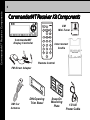
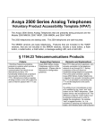
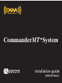
CommanderMT System
installation guide
XMRVRFM002
Table of Contents
2
Table of Contents
Table of Contents ............................................................................................... 2
Congratulations .................................................................................................. 3
FCC Information .................................................................................................. 4
Cautions and Warnings ................................................................................... 5
CommanderMT Receiver Kit Components .............................................. 6
Installation/Wiring Precautions .................................................................... 7
Setting Up and Installing Your Kit ............................................................... 8
Cabling Interconnections ...................................................................... 8
Interconnect Diagram ............................................................................. 9
Antenna Installation ............................................................................. 10
CommanderMT Display Controller Installation ....................... 13
Using the DIN Opening Trim Bezel ............................................ 13
Preferred Location ....................................................................... 13
Locating the Display Controller ............................................ 14
Installing the Mini-Tuner ........................................................... 15
Installing the Cradle and Interconnecting Cables ......... 15
Using the Snap-On Mounting Plate ......................................... 17
Connection Options ........................................................................ 18
FM Direct Wiring ........................................................................... 18
Low-Level Audio Output .......................................................... 19
Warranty ......................................................................................................... 20
3
Thank you for purchasing the Audiovox CommanderMT XM® Satellite Radio
System. You are one step closer to experiencing the latest innovation in XM®
Satellite Radio. XM® Satellite Radio will revolutionize your vehicle or in-home
entertainment.
XM® features over 170 digital channels — The most commercial-free music,
over 30 channels of news, sports, talk and entertainment, over 20 dedicated
channels of XM® Instant Traffic & Weather, and the deepest play-list in the
industry with access to over 2 million titles!
XM® Satellite Radio service gives you the power to choose what you want to
hear - wherever and whenever you want it. XM® is America’s #1 Satellite Radio
provider with over 4 million customers.
Your Audiovox CommanderMT XM® Satellite Radio System consists of accessory Vehicle Kit components required for your specific installation needs.
Required subscription for service sold separately.
Installation costs and other fees and taxes may apply, including a one-time
activation fee. All fees and programming subject to change. College sports
games subject to availability. Subscriptions subject to Customer Agreement
included with the XM Welcome Kit and available at www.xmradio.com. Only
available in the 48 contiguous United States.
© 2007 XM® Satellite Radio Inc. XM® is a trademark of XM® Satellite Radio. All
rights reserved. All other trademarks are the property of their respective
owners.
Congratulations
Congratulations
FCC Information
4
FCC Information
NOTE: This equipment has been tested and found to comply with the limits for
a Class B digital device, pursuant to Part 15 of the FCC Rules. These limits are
designed to provide reasonable protection against harmful in
terference in a residential installation. This equipment generates, uses and can
radiate radio frequency energy and, if not installed and used in accordance with
the instructions, may cause harmful interference to radio communications. How
ever, there is no guarantee that interference will not occur in a particular instal
lation. If this equipment does cause harmful interference to radio or television
reception, which can be determined by turning the equipment off and on, the
user is encouraged to try to correct the interference by one or more of the
following measures:
— Reorient or relocate the receiving antenna.
— Increase the separation between the equipment and receiver.
— Connect the equipment into an outlet on a circuit different from that to which the
receiver is connected.
— Consult the dealer or an experienced radio/TV technician for help.
This device complies with Part 15 of the FCC Rules. Operation is subject to the
following two conditions: (1) This device may not cause harmful interference, and
(2) this device must accept any interference received, including interference that
may cause undesired operation.
The user is cautioned that changes or modifications not expressly approved by XM®
Satellite Radio, Inc. can void the user’s authority to operate this device.
Please note that the cables and antenna wire that has been supplied with your
car installation kit are supplied with permanently attached ferrite beads. It is the
responsibility of the user to use the cable and antenna wire with the ferrite
beads.
By adhering to these warnings and safety considerations, stated in the manual and
by XM®, accidents.
5
1. Do not install the CommanderMT Display Controller in a position
that hinders your view through the windshield, or obstructs viewing
of the dashboard indicators and displays.
2. Do not install the Display Controller where it may obstruct the
operation or deployment of safety devices, such as airbags, etc.
3. Do not allow operation of the unit to detract from safe driving practices; remember that you are responsible as the vehicle operator
to adhere to all safe driving and traffic regulations.
4. By adhering to these warnings and safety considerations, serious
accidents and/or personal injury can be avoided.
Cautions and Warnings
Cautions and Warnings
CommanderMT Receiver Kit Components
^
menu
1
2
3
4
5
6
7
8
XM
Mini-Tuner
^
CommanderMT Receiver Components
6
p/d
9
0
CommanderMT
Display Controller
Interconnect
Cradle
Remote Control
FM Direct Adapter
XM Car
Antenna
DIN Opening
Trim Bezel
Snap-On
Mounting
Plate
12 Vdc
Power Cable
7
1. To prevent a short-circuit, be sure to turn off the ignition and remove
the negative (-) battery cable prior to installation. Connect power
wires last.
2. Do not install the CommanderMT Display Controller in locations exposed to direct sunlight, or in areas subject to extreme
temperatures, or damage could occur.
3. Incorrect installation may cause damage to the system. Mount
the system components using the suggested methods recommended in this manual.
4. Be careful not to crimp or twist the vehicle wiring.
5. Use only the 12 Volt DC Power Cable supplied. Use of an alternative
power source could damage the CommanderMT System components or vehicle wiring.
6. Locate the CommanderMT Display Controller in an area of the
vehicle where it will not obstruct the driver’s operation of the vehicle
and where it will not pose a risk to driver or passengers in the event
of an emergency stop.
Installation/Wiring Precautjions
Installation/Wiring Precautions
Cabling Interconnections
8
Setting Up and Installing Y
our Kit
Your
NOTE: The XM® signal can be received and processed virtually
anywhere as long as there are no obvious satellite signal
obstructions such as nearby buildings, high terrain, parking
garages or tunnels.
1. Cabling Interconnections
You can begin to enjoy XM® Satellite Radio as soon as the
CommanderMT System Vehicle Kit installation is complete. Set
up yourAudiovox CommanderMT System using the following
installation instructions, or enlist the help of a professional
installer:
WARNING:Professional installation is recommended. Failure to
properly follow all installation instructions may result
in personal injury or damage to your CommanderMT
System components, your vehicle, or your vehicle
Audio/Video (A/V) system.
9
Interconnect
Cradle with XM
Mini-Tuner
Power Cable
with 2A
In-line Fuse
XM Antenna
DIN Opening
Trim Bezel
To FM Antenna
To FM Radio
CommanderMT
Display Controller
FM Direct Adapter
Cabling Interconnections
Interconnect Diagram
Important/Antenna Installation
10
2 . Important!
It is very important to make your power connection to a source that
only supplies 12V when the vehicle key is in the accessory or ignition
ON position. A connection to a 12V source that is always on,
regardless of the key position, can lead to a battery drain if the
CommanderMT System is left on when you leave your vehicle.
ACCESSORY
NO ACCESSORY
POSITION
POSITION
Ignition Switch Accessory/On-Off Positions
3. Antenna Installation
Where to locate
•
•
•
Best reception is achieved with the antenna mounted on a flat
portion of a metal vehicle roof with at least 12” x 12” of surface area
and a minimum of 6” from a window or sunroof.
If the vehicle has roof racks or skid ribs, it may be necessary to
mount the antenna off-center.
If the venicle roof does not provide sufficient metal surface area,
then the antenna can be mounted on the metal trunk lid. It is
recommended that it be mounted at least several inches from the
rear window to ensure adequate clearance.
11
1. Do not install the antenna inside the vehicle passenger compartment. Mounting the antenna in the passenger compartment either on the from dashboard, or on
the rear window deck area will cause reception issues
and must be avoided.
2. Mounting the antenna on a non-metalic surface will
also result in severe degradation in reception.
• If an appropriate antenna mounting location cannot be identified,
contact your local retailer installation department for additional
guidance.
Cable routing
• Once you have mounted the antenna in the correct location, plan
how to route the cable from this location to the receiver
Inteconnect Cradle, avoiding blocked passages and any obstructions that could kink, crimp, twist or chafe the cable. If the cable
will come into contact with a rough metal opening, use a rubber
grommet to prevent damage.
• For antenna mounting locations at the front or middle of the roof,
the cable can be routed down along the door jamb and into the
car. In some cars, the cable may be brought into the vehicle
through the grommet in the door jamb which carries the power
window and power door lock wires. If the cable does not fit easily
through this grommet, do not try to force it through. Instead, route
the cable under the weather seal near the bottom of the door.
Antenna Installation
Caution:
Antenna Installation
12
Antenna Mounting Methods
•
For antenna mounting locations at the rear of the roof, the antenna
cable can be routed into the vehicle through the trunk. Always
route the cable under the weather seal near the lowest part of the
trunk to reduce possible water leaks.
•
Use pre-existing wiring channels created by the vehicle manufacturer whenever possible.
Tools required
•
The antenna contains a powerful magnet that will secure it to a
metal roof under normal driving conditions. No additional tools
should be necessary to mount the antenna.
13
Be sure to locate your Display Controller below the top of the dash
in your vehicle to keep the unit within easy reach while driving.
Choosing a lower location in your installation should also make it
easier to manage the cables and achieve a more desirable appearance when the installation is completed. See illustration below and
be sure to locate your Display Controller within the outlined shaded
areas.
Display Controller Installation
4. CommanderMT Display Controller Installation
Display Controller Installation
14
The CommanderMT Display Controller can be installed using
the DIN opening trim bezel or a snap-on mounting plate as
shown below. The trim bezel permits in-dash or center console
mounting, while the mounting plate can be used with optional
custom brackets, such as swivel or vent mounts.
a.
Using the DIN Opening Trim Bezel
Preferred location
Your CommanderMT Receiver Kit includes a DIN opening trim
bezel for mounting the display controller into an existing dashboard or console opening.
Using the DIN Opening
Trim Bezel
15
Using the Snap-On Mounting Plate
To attach the CommanderMT cradle to optional mounting devices
that are readily available at retail, attach the snap-on mounting
plate to the rear of the CommanderMT Display Controller as shown
below.
Examples of Optional
Aftermarket Mounting
Alternatives
Display Controller Installation
b.
Connection Options
16
5. Connection Options
The CommanderMT System provides an audio output signal in
two ways:
a.
FM Direct Wiring - The FM direct adapter supplies a hardwired FM output, provided the FM Frequency option of the XM
Mini-Tuner is turned on and tuned to an unused FM frequency.
XM Antenna
Interconnect
Cradle with XM
Mini-Tuner
FM Direct Adapter
To FM Antenna
To FM Radio
17
ROTATE DIAL TO SELECT
FM frequency
Off
Interconnect Cradle with XM
Mini-Tuner
To Vehicle Radio
Low Level Audio
Inputs
Optional Audio
Cable SAT-RCA
Connection Options
b. Low-Level Audio Output - For vehicle radio head units with
auxiliary audio inputs, the audio signal can be routed through
an optional audio cable (Part No. SAT-RCA) and applied to the
auxiliary inputs of a radio or entertainment system. In this case,
tolisten to the audio. the System Receiver FM modulator option
must be disabled (FM Frequency Off), as indicated in the
CommanderMT System User Guide.
Cable Routing and Component Installation
18
6. Cable Routing and Component Installation
Once you have established power connections, Display
Controller and antenna placement, and audio connection, route
all cables to the location where you will mount the Interconnect
Cradle. When you have plugged the power and antenna jacks
into the cradle, re-use the cable twist ties that were provided
with the power and car antenna cables and always be sure to
gather, bundle, twist-tie, and secure any excess cable remaining after determining the best location for your satellite radio
installation.
XM MINI-TUNER
CRADLE
CRADLE WITH COVER
IN PLACE
COVER
LOCKING
TABS
PLASTIC
RETAINING
COVER
ATTACH VELCRO
PAD OR DOUBLESIDED TAPE HERE
19
Installing the Cradle and Interconnecting Cables - Locate the
Interconnect Cradle in a readily accessible location, such as the
glove compartment, console compartment, or under the
dashboard, so that the XM Mini-Tuner can be removed or
replaced. Note also that the cradle must be situated close
enough to comply with the CommanderMT Display Controller
cable and Power Cable lengths (6’).
b.
Installing the Mini-Tuner - Install the XM Mini-Tuner in the
cradle by inserting the tuner into the cradle slot until the
cradle and tuner connectors mate together. You will feel the
tuner connector click into place. Fold the plastic retainer cover
over the cradle and press down until the cradle tabs lock into
the the cover side holes. The XM Mini-Tuner is now secured in
place in the cradle.
Good installation practices should be observed when mounting
any component to avoid vibration, movement or rattling after
installation. When routing cables, avoid blocked passages and
any obstructions that could kink, crimp, twist, or chafe the
cables. Components should be secured in place using
methods such as Velcro, double-sided foam tape, etc.
Cable Routing and Component Installation
a.
Warranty
20
12 MONTH LIMITED WARRANTY
FM Satellite Radio
XMRVRFM002
AUDIOVOX ELECTRONICS CORPORATION (the Company) warrants to
the original retail purchaser of this product that should, under normal use
and conditions, be proven defective in material or workmanship within 12
months from the date of original purchase, such defect(s) will be repaired
or replaced with new or reconditioned product (at the Company's option)
without charge for parts and repair labor.
To obtain repair or replacement within the terms of this warranty, the
product is to be delivered with proof of warranty coverage (e.g. dated bill
of sale), specification of defect(s), transportation prepaid, to an approved
warranty station or the Company at the address shown below.
This Warranty does not extend to the elimination of externally generated
static or noise, to costs incurred for installation, removal or reinstallation
of the product, or to damage to speakers, accessories, or electrical
systems. Warranty does not apply to malfunction of satellite transmissions, repeater signals or audio systems or to damage caused by poor
installation of included components such as magnetic roof mount antenna, disiplay control unit or receiver docking station.
This Warranty does not apply to any product in the opinion of the Company
that has been damaged through alteration, improper installation, mishandling, misuse, neglect, accident, or by rimoval or defacement of the
factory serial number number/bar code label(s). THE EXTENT OF THE
21
This Warranty is in lieu of all other express warranties or liabilities. ANY
IMPLIED WARRANTIES, INCLUDING ANY IMPLIED WARRANTY OF
MERCHANTABILITY, SHALL BE LIMITED TO THE DURATION OF
THIS WRITTEN WARRANTY. ANY ACTION FOR BREACH OF ANY
WARRANTY HEREUNDER INCLUDING ANY IMPLIED WARRANTY
OF MERCHANTABILITY, MUST BE BROUGHT WITHIN 24 MONTHS
FROM DATE OF ORIGINAL PURCHASE. IN NO CASE SHALL THE
COMPANY BE LIABLE FOR ANY CONSEQUENTIAL OR INCIDENTAL
DAMAGES FOR BREACH OF THIS OR ANY OTHER WARRANTY, EXPRESS OR IMPLIED, WHATSOEVER. No person or representative is
authorized to assume for the Company any liability other than expressed
herein in connection with the sale of this product.
Some states do not allow limitations on how long an implied warranty
lasts or the exclusion or limitation of incidental or consequential damage
so the above limitations or exclusions may not apply to you. This
Warranty gives you specific legal rights and you may also have other
rights which vary from state to state.
U.S.A.:
Audiovox Electronics Corporation
11788 (1-800-645-4994)
150 Marcus Blvd
Hauppauge, New York
Canada: CALL 1-800-645-4994 for Location of Warranty Station Serving Your Area
128-7902A
Warranty
COMPANY'S LIABILITY UNDER THIS WARRANTY IS LIMITED TO THE
REPAIR OR REPLACEMENT PROVIDED ABOVE AND, IN NO EVENT,
SHALL THE COMPANY'S LIABILITY EXCEED THE PURCHASE PRICE
PAID BY PURCHASER FOR THE PRODUCT.
Audiovox Electronics Corporation
150 Marcus Blvd.
Hauppauge, New York 11788
U.S.A.
1 800 645 4994
www.audiovox.com
XM name and related logos are trademarks of XM Satellite Radio Inc.
Printed on Recycled Paper
©2007 Audiovox Electronics Corporation. All rights reserved.
XMRVRFM002