1
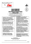
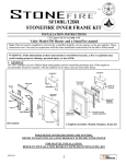
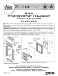
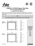
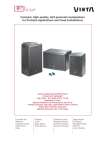
530 B-VENT
GAS FIREPLACE HEATER
Installation & Operating
Instructions
Please read this manual before installing and operating this heater.
This manual should remain with the homeowner.
USE THIS MANUAL IN CONJUNCTION WITH THE MANUAL SUPPLIED
WITH THE 530X ENGINE
WARNING: If the information in these
instructions is not followed exactly, a fire
or explosion may result causing property
damage, personal injury or loss of life.
Do not store or use gasoline or other
flammable vapours and liquids in the vicinity
of this or any other appliance.
WHAT TO DO IF YOU SMELL GAS
Installation and service must be performed
by a qualified installer, service agency or the
gas supplier.
This appliance is a domestic room-heating
appliance. It must not be used for any other
purposes such as drying clothes, etc.
This appliance is suitable for installation in a
bedroom or bed sitting room.
• Do not try to light the appliance.
• Do not touch any electrical switch; do not
use any phone in your building.
• Immediately call your gas supplier from
a neighbor’s phone. Follow the gas
supplier’s instructions.
• If you cannot reach your gas supplier, call
the fire department.
Manufactured by
MILES INDUSTRIES LTD.
British Columbia, Canada
www.milesfireplaces.com
Vous pouvez vous procurer un exemplaire français de ce manuel auprès de votre marchand.
4000343/03
Safety and Warning Information
READ and UNDERSTAND all instructions
carefully before starting the installation.
FAILURE TO FOLLOW these installation
instructions may result in possible fire hazard
and will void the warranty.
Prior to the first firing of the fireplace, READ the
Owner’s Information Section of this manual.
DO NOT USE this appliance if any part has
been under water. Immediately, CALL a
qualified service technician to inspect the unit
and to replace any part of the control system
and any gas control that has been under water.
THIS UNIT IS NOT FOR USE WITH SOLID
FUEL.
Installation and repair should be PERFORMED
by a qualified service person. The appliance and
venting system should be INSPECTED before
initial use and at least annually by a professional
service person. More frequent cleaning may be
required due to excessive lint from carpeting,
bedding, etc. It is IMPERATIVE that the units
control compartment, burners, and circulating air
passageways BE KEPT CLEAN to provide for
adequate combustion and ventilation air.
Always KEEP the appliance clear and free
from combustible materials, gasoline, and other
flammable vapors and liquids.
NEVER OBSTRUCT the flow of combustion and
ventilation air. Keep the front of the appliance
CLEAR of all obstacles and materials for
servicing and proper operation.
Due to the high temperature, the appliance
should be LOCATED out of traffic areas and
away from furniture and draperies. Clothing or
flammable material SHOULD NOT BE PLACED
on or near the appliance.
Children and adults should be ALERTED to
the hazards of high surface temperature and
should STAY AWAY to avoid burns or clothing
ignition. Young children should be CAREFULLY
SUPERVISED when they are in the same room
as the appliance.
This unit MUST be used with a vent system
as described in this Installation manual. NO
OTHER vent system or components MAY BE
USED.
This gas fireplace and vent assembly MUST be
vented directly to the outside and MUST NEVER
be attached to a chimney serving a separate
solid fuel burning appliance. Each gas appliance
MUST USE a separate vent system. Common
vent systems are PROHIBITED.
INSPECT the external vent cap on a regular
basis to make sure that no debris is interfering
with the air flow.
The glass door assembly MUST be in place and
sealed before the unit can be placed into safe
operation.
DO NOT OPERATE this appliance with the
glass door removed, cracked, or broken.
Replacement of the glass door should be
performed by a licensed or qualified service
person. DO NOT strike or slam the glass door.
The glass door assembly SHALL ONLY be
replaced as a complete unit, as supplied by
the fireplace manufacturer. NO SUBSTITUTE
material may be used.
DO NOT USE abrasive cleaners on the glass
door assembly. DO NOT ATTEMPT to clean the
glass door when it is hot.
Turn off the gas before servicing this appliance.
It is recommended that a qualified service
technician perform an appliance check-up[ at
the beginning of each heating season.
Any safety screen or guard removed for
servicing must be replaced before operating this
appliance.
DO NOT place furniture or any other
combustible household objects within 36” of the
fireplace front.
Options
Heater engine unit #530XAN/P/XCN/P and B-vent conversion kit #552BVK is used with all
installations.
The 530 B-Vent installation requires the cast iron stove #531CSB—Cast Stove Black.
Additional optional features
Circulating Fan Kit #555CFK.
Having variable speed and temperature control, it is designed to boost the natural convection
process through the appliance. It may be fitted before the fireplace is installed or retrofitted at a
later date.
LPG Conversion Kit #554LPK.
Burner & injector kit for conversion from natural gas to propane.
Dimensions & Clearances
Side projection “A”
Up to 8”
More than 8”
Min. clearance from
appliance side “B”
1”
6”
General
Approvals & codes
This appliance is certified by International Approval Services for use in Canada and the USA. The
appliance is for installation connected to an approved 4” metal B type vent.
This appliance is supplied for use with natural gas. It can be converted for use with LP gas with Kit
#554LPK.
The appliance complies with CGA P.4.1, Testing method for measuring annual fireplace efficiencies.
The installation must conform with local codes or, in the absence of local codes with the National Fuel
Gas Code, ANSI Z223.1or the Canadian installation code CAN/CGA-149. Only qualified licensed or
trained personnel should install the appliance.
Ratings
Altitude (ft)
Input Maximum (Btu/h)
Input Mnimum (Btu/h)
Manifold Pressure (in w.c.)
Minimum Supply Pressure (in w.c.)
Natural Gas
0–4,500 2
20,500
6,500
3.5–3.9
5.0
Propane Gas 1
19,000
12,500
10.3–10.7
11.0
¹When converted using kit #554LPK
²Tested to CAN/CGA - 2.17 Gas fired appliances for use at high altitudes. In the USA installations
may require deration over 2000ft - Check local codes.
Location
The President FS can be installed as a free standing unit with connected to a suitable type “B” vent or
connected to an existing masonry chimney—see the section Dimensions & Clearances on page 3.
The installation must conform to the minimum clearance dimensions shown in Dimensions &
Clearance on page 3.
An existing masonry chimney must be cleaned and checked to make sure that it is safe for use.
Reline the chimney with an approved 4” flue liner installed according to the instructions supplied with
the liner.
The appliance is suitable for fixing to the floor. If the appliance is installed directly on carpeting, tile
or other combustible material other than wood flooring, it must be installed on a metal or wood panel
extending the full width and depth of the appliance.
CAUTION! A GAS APPLIANCE MUST NOT BE CONNECTED TO A CHIMNEY FLUE SERVING A
SEPARATE SOLID-FUEL BURNING APPLIANCE.
Supply Gas
•
•
•
All appliances are supplied for installation with natural gas. The supply pressure must be between
the limits shown in section Ratings of this manual.
The supply connection is 3/8’’NPT.
The opening for the gas supply line is at the rear left corner of the appliance.
Pack Contents
#552BVK B-Vent Conversion Kit
1
B-vent adapter unit with vent switch
1
Thermocouple interrupter
1
Case rear cover plate
2
“P” clips (for wire fastening)
Take care when removing the contents from the packaging to prevent damage. Check that all the
contents are in the packs and are undamaged.
Note: The restrictor plates supplied with the 530 engine are NOT required for the B-vent
installation.
Appliance Preparation
Detach the window.
Refer to the Installation Instructions supplied with the 530 Engine.
Check ignition spark.
Refer to the Installation Instructions supplied with the 530 Engine.
B-Vent Conversion Kit Installation
1. Remove the rear outlet vent collar and seal
by unscrewing 12 screws.
3. Remove 4 screws from the case back (2 each
side just outside of the cover plate). Fit the
adapter unit to the case using these screws.
. Fit the rear cover plate (supplied with the
kit) using the seal and 12 screws previously
removed. The hole in the cover plate must
be nearest the top edge.
4. Fit a “P” clip at the bottom rear right corner of
the appliance case. Fit the vent switch wire to
the clip. Feed the wire into the case through the
hole at the bottom corner.
Adapting Burner Module
1. Detach the battery shield by removing two
screws.
. Detach the burner module by removing 11
screws.
5. Fit the thermocouple interrupter block to the
valve. Do not overtighten. Finger tighten approximatively 1/4 of a turn.
3. Fit a “P” clip at the right side of the inside of
the case. Fit the vent switch wire to the clip.
6. Connect the vent switch wires into the
thermocouple interrupter block. Screw the
thermocouple into the interrupter block
until finger tight. Make sure that the wires
are properly located and finally tighten the
thermocouple nut (approx. 1/4 turn) with a
wrench to secure the wires with good contact.
4. Disconnect the thermocouple from the regulator block.
7. If the appliance is to be fixed to the floor, don’t
attach the burner module to the appliance
yet. Wait until the appliance is accurately
positioned with the B-vent attached. The holes
in the appliance base for floor fixing are not
accessible when the burner module is fitted.
Attaching top air deflector
Refer to the Installation Instructions supplied with the 530 engine.
Floor Fixing
Refer to the Installation Instructions supplied with the 530 engine.
Venting & Appliance Fixing
Refer to the Installation Instructions supplied with the 530 engine.
Gas Supply Installation
Refer to the Installation Instructions supplied with the 530 engine.
Aeration Setting Check
Refer to the Installation Instructions supplied with the 530 engine.
Ceramic Fuel Bed Installation
Refer to the Installation Instructions supplied with the 530 engine.
Window Refitting & Checking
Refer to the Installation Instructions supplied with the 530 engine.
Operation Checks
Burner operation
Refer to the Installation Instructions supplied with the 530 Engine.
Aeration adjustment
Refer to the Installation Instructions supplied with the 530 Engine.
Venting
A check for correct venting of combustion products must be made before the installed heater is left
with the customer. The test should be made in the following manner.
1. Light the heater.
. Turn the gas control to the on position and thermostat to the highest setting.
3. After the appliance has been alight for five minutes place smoke match or taper inside the opening
in the B-vent adapter box. See figure below.
The installation is satisfactory if the smoke is drawn into the adapter box and up to the vent pipe.
If the vent is blocked or has strong reverse flow, the thermally actuated switch mounted in the adapter
box will automatically shut off the gas supply within about ten minutes. If the smoke is not drawn in,
leave for about ten minutes and then try again.
If the smoke is still not drawn into the adapter and vent pipe, turn the heater off and check cause of
lack of draft, if necessary get expert advice.
Installation Completion
Refer to the Installation Instructions supplied with the 530 engine.