1
Gryphon™ GFE4400
Fixed Area Imaging
Bar Code Scan Engine
Integration Guide
Datalogic ADC, Inc.
959 Terry Street
Eugene, Oregon 97402
USA
Telephone: (541) 683-5700
Fax: (541) 345-7140
An Unpublished Work - All rights reserved. No part of the contents of this documentation or the procedures described therein may be reproduced or transmitted in any form or by any means without prior
written permission of Datalogic ADC, Inc. or its subsidiaries or affiliates ("Datalogic" or “Datalogic ADC”).
Owners of Datalogic products are hereby granted a non-exclusive, revocable license to reproduce and
transmit this documentation for the purchaser's own internal business purposes. Purchaser shall not
remove or alter any proprietary notices, including copyright notices, contained in this documentation
and shall ensure that all notices appear on any reproductions of the documentation.
Should future revisions of this manual be published, you can acquire printed versions by contacting
your Datalogic representative. Electronic versions may either be downloadable from the Datalogic website (www.datalogic.com) or provided on appropriate media. If you visit our website and would like to
make comments or suggestions about this or other Datalogic publications, please let us know via the
"Contact Datalogic" page.
Disclaimer
Datalogic has taken reasonable measures to provide information in this manual that is complete and
accurate, however, Datalogic reserves the right to change any specification at any time without prior
notice.
Datalogic and the Datalogic logo are registered trademarks of Datalogic S.p.A. in many countries,
including the U.S.A. and the E.U. All other brand and product names may be trademarks of their respective owners.
Table of Contents
Gryphon™ GFE4400 Integration Guide ................................................... 1
Overview ............................................................................................................................... 1
Unpacking the Scan Engine ................................................................................ 2
Scan Engine Care .................................................................................................... 2
Technical Support ............................................................................................................. 3
Datalogic Website Support ................................................................................. 3
Telephone Technical Support ............................................................................ 3
Mounting the Scanner .............................................................................. 4
General Considerations ................................................................................................... 4
Mounting .............................................................................................................................. 4
Mounting the Scanner Standalone .................................................................. 5
Scan Engine Electrical Connections ................................................................. 5
Host Interface ........................................................................................................... 5
USB .................................................................................................................... 7
RS-232 .............................................................................................................. 8
External Trigger and Digital Output ..................................................... 8
User Interface .............................................................................................. 10
Good Read Beep Interface ................................................................................12
Scanner Ventilation ........................................................................................................13
Integrating the Scanner to Read at the Proper Distance ....................... 14
Design of the Scanner Opening ................................................................................. 15
Integrating the Scanner Behind a Window ............................................................ 16
ESD Protection ..................................................................................................................17
Technical Specifications .........................................................................18
RS-232 Electrical Connections .............................................................. 22
Indicators ............................................................................................................................ 23
Error Codes ........................................................................................................................ 24
Mechanical Specifications ......................................................................25
Physical Properties .......................................................................................................... 25
Scanner Dimensions ....................................................................................................... 25
Clearance Required for Integration .......................................................................... 27
NOTES
Gryphon™ GFE4400
Integration Guide
This document gives instruction, mechanical details, and design considerations to integrate the Gryphon™ GFE4400 model (designated as
“scan engine” or “OEM scan engine” in this manual) specifically into
equipment-integrated scanning applications.
Overview
The GFE4400 OEM scan engine is a compact, decoded, omni-directional imaging scan engine for fixed position OEM integration, such as
price verifiers, kiosks, vending machines, point-of-sale (POS) terminals,
and other equipment-integrated scanning applications. The new proprietary imaging technology excels at capturing hard-to-read bar codes in
omni-direction orientation.
A typical system using the scan engine consists of a host system such as a
price verifier or kiosk. The host system interfaces with the scan engine
and receives decoded bar code data produced by the scan engine. The illumination LEDs in the scan engine emit visible light when a bar code
passes through the scan volume area and light is reflected off the bar code.
The scan engine collects this reflected light, processes it into a digital signal and decodes it into data that can be used by the host system. The scan
engine has different operational modes which can be selected via special
programming bar codes.
The OEM scan engine is the same reader as that found in the Gryphon
Integration Guide
1
Gryphon™ GFE4400 Integration Guide
GFS4400 scan module. This document is meant to give instruction, mechanical details, and design considerations to integrate the OEM scan engine model only.
Details on the Configuration Settings and Programming are found in the
GFS4400 Product Reference Guide (PRG). The Datalogic Aladdin Configuration Utility (available free from the Datalogic website) can also be
used to modify settings.
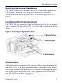
Unpacking the Scan Engine
The scan engine is shipped in custom packaging. Carefully open the package, and inspect for the following:
•
scan engine
•
power supply (if ordered)
•
interface cable (if ordered)
If any parts are damaged or you need additional hardware, please contact
Technical Support.
Scan Engine Care
The scan engine contains sensitive components which require special handling. Datalogic may not warrant damage due to improper handling.
2
•
Do not disassemble the scan engine. Doing so will void the warranty.
•
Use standard ESD precautions & policies when handling the
GFE 4400 scan engine.
•
Avoid touching the camera lens. Fingerprints will degrade the
scan engine's performance.
Gryphon™ GFE4400
Gryphon™ GFE4400 Integration Guide
Technical Support
Datalogic Website Support
The Datalogic website (www.datalogic.com) is the complete source for
technical support and information for Datalogic products. The site offers
product support, product registration, warranty information, product
manuals, product tech notes, software updates, demos, and instructions
for returning products for repair.
Telephone Technical Support
If you do not have internet or email access, you may contact Datalogic
technical support at (541) 349-8283 or check the back cover of your
manual for more contact information.
Integration Guide
3
Mounting the Scanner
This section describes how to design the mounting for optimum scanner
performance.
General Considerations
A typical system uses the scanner mounted inside a host enclosure, with
an opening for the scanning pattern to exit and read bar codes. The opening should be the size of the scanner field of view at a minimum, but only
exposing as much of the scanner as necessary.
Although the scanner has been designed to be rugged, it is important to
consider the effect of the environment on the scanner. In particular,
mounting should minimize the possibility of foreign objects coming into
contact with the electronics. Such contact could damage the device or reduce the scanner's performance.
Mounting
The primary method of mounting to the host enclosure is to attach the
scanner using the three mounting holes provided in the main PCBA. "Mechanical Specifications" on page 25 has mechanical drawings of the scanner, including the position of the mounting features.
The scanner can be mounted upside down with no loss in scanning performance.
4
Gryphon™ GFE4400
Mounting the Scanner
Mounting the Scanner Standalone
The OEM scanner is not intended for use in a standalone application.
This model is intended to be integrated inside a host enclosure.
GFS4400 models should be used when a standalone application is required.
Scan Engine Electrical Connections
The GFE4400 scan engine has three application ports for device integration, as indicated below, a Host (J1), User (J2), and Good Read Beep Interface.
Figure 1. Scan Engine Application Ports
J3 Beep Interface
J2 User Interface
J1 Host Interface
Host Interface
The Host Interface connection (J1) provides all the connection points for
either RS-232 or USB host communications. Additionally, this connector is input for power and provides access to the external triggering input
and digital signal output functions. The assignment of the connector
pins are indicated in Table 1 on page 6.
Integration Guide
5
Mounting the Scanner
Table 1. J1 Connector Pins Assignment
Pin Number
1
2
3
4
5
6
7
8
9
10
11
12
Pin Functionality
USB D+
USB DUSB Shield
USB Shield
EXT_TRIGGER_IN; (input to the base of a transistor, pull
high to activate)
RS232 TXD (output from scanner)
RS232 RTS (output from scanner)
RS232 RXD (input to the scanner)
RS232 CTS (input to scanner)
DIGITAL_OUT (open collector)
+5V (USB Vbus or external power adapter)
GND
The J1 connection on the GFE4400 scan engine is a Hirose,
DF13C-12P-1.25V,12 circuit connector. For application integration the
recommended mating plug is DF13-12S-1.25C housing with
DF13-12S-1.25C wire crimp terminals.
Figure 2. Interface Board (bottom view)
J1
Pin1
6
Gryphon™ GFE4400
Mounting the Scanner
USB
For USB setup, the recommended wiring is the following. A compatible
USB cable is available from Datalogic, part number: 770111600.
Figure 3. USB Cabling
It is important that connections 7/8/9 be wired together for USB Auto
Detection.
Integration Guide
7
Mounting the Scanner
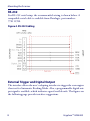
RS-232
For RS-232 serial setup, the recommended wiring is shown below. A
compatible serial cable is available from Datalogic, part number:
770111700.
Figure 4. RS-232 Cabling
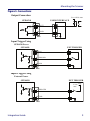
External Trigger and Digital Output
The interface allows the user's adapting interface to trigger the scan engine
if not set for Automatic Reading Mode. Also, a programmable digital output signal is available, which indicates a good read/decode. The figures on
the following page provide interface suggestions.
8
Gryphon™ GFE4400
Mounting the Scanner
Figure 5. Connections
Output Connection
Vext 14Vdc max
GFE44X0
USER INTERFACE
c
10 OUT
12 GND
HRS
Input Trigger Using
GFE44X0 Power
GFE44X0
EXT TRIGGER
11 VCC
5 TRIGGER
12 GND
HRS
Input Trigger Using
External Power
GFE44X0
EXT TRIGGER
5 Vdc
max
Vext
5 TRIGGER
12 GND
HRS
Integration Guide
9
Mounting the Scanner
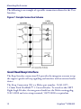
User Interface
The User Interface connection (J2) provides the integrator a means to
monitor scan engine status (LEDs), and offers an additional mechanism
for manually triggering the device.
The user connection (J2) uses a Molex part number, 0527460671,
0.50mm (.020") Pitch FFC/FPC Connector, Right Angle, SMT, ZIF,
Bottom Contact Style, 6 Circuits, Gold Contact Plating. For custom adaptations, the integrator must interface using an FFC (Flat Flexible Cable)
that mates properly to scan engine ZIF connector.
Figure 6. Top view
Pin 1
J3
J2
Pin 1
The assignment of the J2 connector pins are indicated in the following table.
10
Gryphon™ GFE4400
Mounting the Scanner
Table 2. J2 Connector Pins
Pin Number
1
2
3
4
5
6
Pin Functionality
LED1 Ctrl Signal, Trigger (active low)
LED2 Ctrl Signal, Status (open collector active low)
LED3, Power, (hard wired to VCC internally)
VCC_Out (5v for LED supply)
Trigger Switch+
Trigger Switch- (ground)
The following table outlines scan engine status assigned to each LED
(with recommended colors).
L3
POWER
(yellow
ON = Power ON
OFF = Power OFF
ON = Good Read
L2
L1
S1
Integration Guide
STATUS
(green)
TRIGGER
(blue)
SWITCH
Blinks = USB enumeration or interface inactive or waiting for change of configuration
ON = External trigger or button pressed or
phase active
Blinks = During transfer of captured image,
or during Flash memory updates
Press for manual-controlled trigger
11
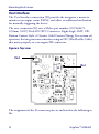
Mounting the Scanner
The following is an example of a possible connection scheme for the User
Interface:
Figure 7. Sample Connection Scheme
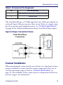
Good Read Beep Interface
The Beep Interface connection (J3) provides the integrator a means to tap
the engine's good read beep signaling and interface with an external audio
device.
The Beep Connection (J3) is a Molex part number, 53261-0271,
1.25mm Pitch PicoBlade™ 2 Circuit Header. To attach to this SMT
Right Angle Header, the integrator should use the Molex mating plug,
51021-0200 and wire crimp terminal, 50079-8000 or equivalent.
12
Gryphon™ GFE4400
Mounting the Scanner
Table 3. J3 Connector Pin Assignment
Pin
Pin Functionality
1
2
Good Read Beep Signal (open collector, active low)
Common (gnd)
The Good Read Beep is a 2750Hz signal burst for 100ms provided by an
on board Open Collector transistor drive circuit. Below is a simple example of an external audio implementation. See "Technical Specifications"
on page 18 for additional information about Good Read Beep output.
Figure 8. Beeper Connection Scheme
Scanner Ventilation
When mounting the scanner inside an enclosure, it is important to have
proper ventilation to ensure that the scanner temperature does not exceed the maximum range as listed in "Technical Specifications" on
page 18. The reliability of the scanner may be compromised if the temperature range is not maintained.
Integration Guide
13
Mounting the Scanner
Integrating the Scanner to Read at the Proper Distance
When deciding how to mount the OEM scanner, there are many criteria
that must be considered. First, there are minimum and maximum distances that the bar code can be from the front of the scanner to be properly
read, depending on the size of the bar code. These distances, or depth of
field, are specified in "Technical Specifications" on page 17.
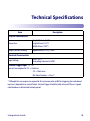
The scanner must be positioned so that the scan volume and illumination
light will cover the entire bar code. The scan volume is shown in Figure 9.
The combination of the Scan Volume and the illumination light is called
the Field of View. Designing around the scanner Field of View is explained more in the following section.
Figure 9. Scanning Volume
106mm
169mm
Scan Volume @ 188mm
14
Gryphon™ GFE4400
Mounting the Scanner
Design of the Scanner Opening
The design and placement of the scanner opening within a host enclosure
are critical for optimum system performance. A typical system uses the
scanner mounted inside a host enclosure, with an opening to allow the
scanner Field of View to exit the scanner window and read bar codes.
Use the following guidelines to design the host enclosure and scanner
opening, along with the dimensions shown in "Mechanical Specifications"
on page 25.
•
The opening must not block any of the outgoing illumination
light, described by dimensions of the scanner Field of View.
•
Ensure that there are no reflective surfaces around the area of the
scanner opening.
•
The minimum opening size must increase as the distance
between the scanner and the host enclosure window increases.
This is necessary to accommodate the width and height of the
scan volume.
•
The opening or other parts of the host enclosure must not enter
the Field of View in order to allow the bar code image to be captured by the scanner.
•
If the scanner is flush against the opening, the opening must be
the size of the scanner at a minimum, but only exposing as much
of the front surface of the scanner as necessary.
Integration Guide
15
Mounting the Scanner
Integrating the Scanner Behind a Window
The addition of a host enclosure window could
degrade scanner performance. This is due to the
optical reflective surfaces that will cause interference with the imaging technology.
CAUTION
It is recommended to conduct scan performance testing with any window
to determine if the performance level is acceptable for the application.
•
Window material should be transparent with 92% transmission
to wavelength 625nm and 850nm.
•
Only a flat window must be used.
•
The window should be as thin as possible (thickness less than
2mm).
•
The window should be as close to the illumination LEDs as possible to avoid LED ghost images or light reflections. Tilting the
window and/or anti-reflective coating can help mitigate illumination reflections.
Performance degradation may include:
16
•
The scan module will not read very low contrast labels.
•
The scan module will not be able to wake up, especially in low
ambient light (typically <100Lux). In this case, the scan module
may need its wakeup sensitivity setting increased.
Gryphon™ GFE4400
Mounting the Scanner
ESD Protection
The host enclosure design must provide adequate ESD protection for the
scanner. Ideally, static discharge should not be allowed to discharge to
the scanner. The preferred method to prevent static discharge is to provide a long discharge path to all circuits. The scanner is intended to be
mounted inside a host enclosure. Only the front surface should be exposed in order to read bar codes. This is to protect the rear interface connector area, which can be susceptible to static discharge. Interface cables
should also not have power applied when inserted into the scanner. Any
metal mounting surfaces for the scanner must be electrically grounded
with proper insulation to the scan engine mounting.
Static discharge (ESD) testing is recommended for the entire system integration to ensure proper ESD protection.
Proper ESD protection should be used at the time of installation and servicing of the scanner or the host equipment.
ESD
Integration Guide
17
Technical Specifications
Item
Description
Physical Characteristics
Dimensions
Height 28.2mm (1.11")
Length 42mm (1.65")
Width 48 mm (1.89")
Weight (without cabling)
Approximately 51.2 g (1.8 oz)
Electrical Characteristics
Input Voltage
5 VDC ± 5%
Overvoltage tolerant to 14VDC
External Trigger Input : 1V - 5V
Current Consumption for 1V = 2mA max
5V = 10mA max
Min Pulse Duration = 25ms *
* Although the scan engine can respond to this minimum pulse width for triggering, bar code decoding time is dependent on several factors. External Trigger should be held active until there is a good
read decode or a determined timeout period.
Integration Guide
18
Technical Specifications
Item
Description
Digital Output : Open Collector
Vout
14VDC
Vce
20 VDC max
Collector Current
40 mA continuous max
Vce Saturation
0.3 V max at 15 mA
Power Dissipation
80 mW max at 50 °C (ambient temperature)
Good Read Beep Output
Output Type
Open Collector
Maximum Sink Current
200mA
Maximum Sink Voltage
5V (ESD protection limit)
Current & Power Consumption
Input current at 5V in Automatic (Object Sense) Reading Mode
Operating (typical)
175 mA (OnLine & Serial OnLine Modes)
165 mA (Automatic Object Sense Mode)
Operating (max)
180 mA
Idle/standby (typical)
53 mA (OnLine & Serial OnLine Modes)
100 mA (Automatic Object Sense Mode)
No idle in Automatic Mode
Performance Characteristics
Nominal Frame Rate
53 frames/second
Light Source
Dual Red LEDs
Roll (Tilt) Tolerance
Up to ± 180°
Integration Guide
19
Technical Specifications
Pitch Tolerance
± 40°
Skew (Yaw) Tolerance
± 40°
Print Contrast Minimum
25% minimum reflectance
Field of View
40° H x 26° V
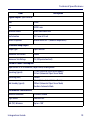
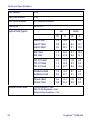
Depth of Field (Typical)
Minimum Element Width
20
cm
inches
NF
FF
NF
FF
Code 39 5mil
Code 39 10mil
Code 39 20mil
3.8
0.8
0.2
16.8
32.3
48.3
1.5
0.3
0.1
6.6
12.7
19.0
EAN 7.5mil
EAN 13mil
1.9
1.6
26.4
41.0
0.7
0.6
10.4
16.1
PDF-417 6.6mil
PDF-417 10mil
PDF-417 15mil
2.4
1.3
1.6
14.5
23.0
34.7
1.0
0.5
0.6
6.0
9.4
13.6
DataMatrix 10mil
DataMatrix 15mil
1.8
0.3
16.2
23.7
0.7
0.1
6.4
9.3
QR Code 10mil
QR Code 15mil
2.6
0.0
15.1
23.4
1.0
0.0
5.9
9.2
1D Min Resolution = 4 mil
PDF-417 Min Resolution = 5 mil
Datamatrix Min Resolution= 7 mil
Gryphon™ GFE4400
Technical Specifications
Decode Capability
1D Bar Codes
UPC/EAN/JAN (A, E, 13, 8); UPC/EAN/JAN (including P2 /P5); UPC/EAN/JAN (including; ISBN / Bookland & ISSN);
UPC/EAN Coupons; Code 39 (including full ASCII); Code 39 Trioptic; Code39 CIP (French Pharmaceutical);
LOGMARS (Code 39 w/ standard check digit enabled); Danish PPT; Code 32 (Italian Pharmacode 39); Code 128;
Code 128 ISBT; Interleaved 2 of 5 ; Standard 2 of 5; Interleaved 2 of 5 CIP (HR); Industrial 2 of 5; Discrete 2 of 5;
Datalogic 2 of 5 (China Post Code/Chinese 2 of 5); IATA 2of5 Air cargo code; Code 11; Codabar; Codabar (NW7);
ABC Codabar; EAN 128; Code 93 ; MSI; PZN; Plessey; Anker Plessey; GS1 DataBar Omnidirectional; GS1 DataBar
Limited; GS1 DataBar Expanded; GS1 DataBar Truncated; DATABAR Expanded Coupon.
* 13 mils DOF based on EAN. All others are Code 39. All labels grade A, minimum illumination 100 lux, 20°C, label
inclination 10°, static reading. Measured from illumination LEDs.
2D / Stacked Codes
The Gryphon I GFS4400 scanner is capable of decoding the following symbologies using multiple frames (i.e.
Multi-Frame Decoding).
Datamatrix; Inverse Datamatrix; Datamatrix is configurable for the following parameters:; Normal or Inverted;
Square or Rectangular Style; Data length (1 - 3600 characters); Maxicode; QR Codes (QR, Micro QR and Multiple
QR Codes); Aztec; Postal Codes - (Australian Post; Japanese Post; KIX Post; Planet Code; Postnet; Royal Mail Code
(RM45CC); Intelligent Mail Barcode (IMB); Sweden Post; Portugal Post); LaPoste A/R 39; 4-State Canada;
PDF-417; MacroPDF; Micro PDF417; GS1 Composites (1 - 12); Codablock F; French CIP13a; GS1 DataBar Stacked;
GS1 DataBar Stacked Omnidirectional; GS1 DataBar Expanded Stacked; GSI Databar Composites; Chinese
Sensible Code; Inverted 2D codesb.
a
It is acceptable to handle this with ULE
b
The SW can apply the Normal/Reverse Decoding Control to the following symbologies: Datamatrix,
QR, Micro QR, Aztec and Chinese Sensible Code.
NOTE: The Scanner can also decode mirrored images of 2D matrix codes Datamatrix, QR Code and
Maxicode.
Host Interface supported
Integration Guide
RS-232
USB (full speed)
21
Technical Specifications
User Environment
Operating Temperature
-4° to 122° F (-20° to 50° C)
Storage Temperature
-4° to 158° F (-20° to 70° C)
Humidity
Operating: 5% to 90% relative humidity, non condensing
Ambient Light immunity
Up to 100,000 Lux
Regulatory
LED Emission Class
(IEC-62471:2006-07) Exempt (No Risk)
IEC60825-1: 2007
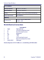
RS-232 Electrical Connections
9-pin connector
1
2
3
4
5
6
7
8
9
Trigger
TX
RX
NC
GND
VCC
CTS
RTS
DIGITAL OUTPUT
Trigger signal input
Transmit Data (output from scanner)
Receive Data (input to scanner)
Not connected
Ground
+5Vdc
Clear To Send (input to scanner)
Request To Send (output from scanner)
Output signal
Default configuration is RS-232: 9600, 8, N, 1, no handshaking, ACK/NAK disabled.
22
Gryphon™ GFE4400
Technical Specifications
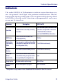
Indicators
The reader’s LED L2 of J2 illuminates to indicate various functions or errors. An optional “Green Spot” also performs useful functions. The following tables list these indications. One exception to the behaviors listed
in the tables is that the reader’s functions are programmable, and so may
or may not be turned on.
Indicator
Description
LED L2 of J2
Good Read
A label has been successfully scanned by
the reader.
LED2 and Green Spot LED behavior for this
indication is configurable via the feature
“Good Read: When to Indicate”
(see the GFS4400 PRG for information.)
ROM Failure
There is an error in the reader's software/programming
Flashes
Configuration
Programming
Mode
The scan engine is ready to read a configuration label or a command from the Aladdin Configuration Utility.
The LED blinks continuously.
Reader
Disabled
The reader has been disabled by the host.
The LED blinks continuously.
Green Spota
flashes
momentarily
Upon successful read of a label, the software shall turn the green spot on for the
time specified by the configured value.
N/A
Image Capture
On when ready to capture image
Blue LED on
Flash Memory
Update
Occurs while update is in progress
Blue LED blinks
a
Except when in sleep mode or when a Good Read LED Duration other than 00 is selected
Integration Guide
23
Technical Specifications
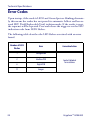
Error Codes
Upon startup, if the reader’s LED2 and Green Spot are blinking alternately, this means the reader has not passed its automatic Selftest and has entered FRU (Field Replaceable Unit) isolation mode. If the reader is reset,
the sequence will be repeated. Press and release the trigger to see the FRU
indication code from LED2 flashes.
The following table describes the LED flashes associated with an error
found.
24
Number of LED2
Flashes
Error
1
Configuration
2
Interface PCB
6
Digital PCB
11
Imager
Corrective Action
Contact Helpdesk
for assistance
Gryphon™ GFE4400
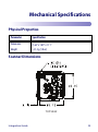
Mechanical Specifications
Physical Properties
Parameter
Specification
Dimensions
42.0mm x 48.0mm x 28.2mm
(1.65" x 1.89" x 1.11"
Weight
~51.2 g (1.8 oz)
Scanner Dimensions
TOP VIEW
Integration Guide
25
Mechanical Specifications
Scanner Dimensions (continued)
BOTTOM VIEW
SIDE VIEW
26
Gryphon™ GFE4400
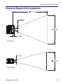
Mechanical Specifications
Clearance Required for Integration
TOP VIEW
SIDE VIEW
Integration Guide
27
Mechanical Specifications
NOTES
28
Gryphon™ GFE4400
Mechanical Specifications
NOTES
Integration Guide
29
Mechanical Specifications
NOTES
30
Gryphon™ GFE4400
ᳮ
O
O
O
X
X
X
⬉䏃ᵓ㒘ӊ
ܝᄺ㒘ӊ
ܝᄺ㒘ӊ
Printed Circuit Board Assembly
Assy, Optics Block
Assy, Module
O
O
O
叏
Hexavalent
Chromium
(Cr(VI))
O
O
O
ચ卲
O
O
O
ᄙᄽ侶
O
O
O
ᄙᄽԲㅘ
Polybrominated
diphenyl ethers
(PBDE)
China RoHS
Polybrominated
biphenyls
(PBB)
Ქኂ‛凝ᚗర⚛
Cadmium
(Cd)
OઍᱝẊㇱઙ⊛ᚲဋ凝ޗறխࢬܶऱ具Ẋڶڶ୭ढ凝݁܅Պխ䦀Գا٥ࡉ㧺ॾஒ䣈䢓ຝᚲ咒ؒ⊛
ޝ䶣ॾஒ䣈խڶڶ୭ढ凝ऱૻၦޣρ(SJ/T 11363-2006) 億ࡳऱૻၦޕ
X:ઍᱝẊㇱઙᚲ↪⊛ဋ凝ޗறխ, ⥋ዋ৻㮕᧚ᢱᚲ⊛Ქኂ‛凝Պխ䦀Գا٥ࡉ㧺ॾஒ䣈䢓ຝᚲ咒ؒ⊛
ޝ䶣ॾஒ䣈խڶڶ୭ढ凝ऱૻၦޣρ(SJ/T 11363-2006) 億ࡳऱૻ㊂
PART
卋
Mercury
(Hg)
ㇱઙฬ⒓
Lead
(Pb)
www.datalogic.com
Datalogic ADC, Inc.
959 Terry Street
Eugene, OR 97402
USA
Telephone: (541) 683-5700
Fax: (541) 345-7140
© 2012 Datalogic ADC, Inc.
820049414 (Rev. X2)
June 2012