1
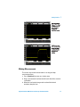
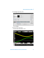
Agilent Infiniium
9000 Series
Oscilloscopes
Evaluation Guide
The most recent PDF version of this
guide will be placed on the Agilent
web site at:
http://cp.literature.agilent.com/litweb/pdf/N2918-97003.pdf
Notices
© Agilent Technologies, Inc. 2009
No part of this manual may be
reproduced in any form or by any
means (including electronic storage and retrieval or translation
into a foreign language) without
prior agreement and written consent from Agilent Technologies,
Inc. as governed by United States
and international copyright laws.
Manual Part Number
N2918-97003
Edition
Third edition, August 2009
Printed in U.S.A.
Agilent Technologies, Inc.
1900 Garden of the Gods Rd.
Colorado Springs, CO 80907 USA
Warranty
The material contained in this
document is provided “as is,”
and is subject to being changed,
without notice, in future editions.
Further, to the maximum extent
permitted by applicable law, Agilent disclaims all warranties,
either express or implied, with
regard to this manual and any
information contained herein,
including but not limited to the
implied warranties of merchantability and fitness for a particular
purpose. Agilent shall not be liable for errors or for incidental or
consequential damages in connection with the furnishing, use,
or performance of this document
or of any information contained
herein. Should Agilent and the
user have a separate written
agreement with warranty terms
covering the material in this document that conflict with these
terms, the warranty terms in the
separate agreement shall control.
ject to Agilent Technologies’ standard commercial license terms,
and non-DOD Departments and
Agencies of the U.S. Government
will receive no greater than
Restricted Rights as defined in
FAR 52.227-19(c)(1-2) (June
1987). U.S. Government users will
receive no greater than Limited
Rights as defined in FAR 52.227-14
(June 1987) or DFAR 252.227-7015
(b)(2) (November 1995), as applicable in any technical data.
Safety Notices
CAU TI O N
A CAUTION notice denotes a
hazard. It calls attention to an
operating procedure, practice, or the like that, if not correctly performed or adhered
to, could result in damage to
the product or loss of important data. Do not proceed
beyond a CAUTION notice
until the indicated conditions
are fully understood and met.
Technology Licenses
The hardware and/or software
described in this document are
furnished under a license and may
be used or copied only in accordance with the terms of such
license.
Restricted Rights
Legend
If software is for use in the performance of a U.S. Government
prime contract or subcontract,
Software is delivered and licensed
as “Commercial computer software” as defined in DFAR
252.227-7014 (June 1995), or as a
“commercial item” as defined in
FAR 2.101(a) or as “Restricted
computer software” as defined in
FAR 52.227-19 (June 1987) or any
equivalent agency regulation or
contract clause. Use, duplication
or disclosure of Software is sub-
2
WA RN ING
A WARNING notice denotes
a hazard. It calls attention to
an operating procedure,
practice, or the like that, if
not correctly performed or
adhered to, could result in
personal injury or death. Do
not proceed beyond a
WARNING notice until the
indicated conditions are fully
understood and met.
Agilent Infiniium 9000 Series Oscilloscope
Evaluation Guide
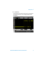
Does your job require an oscilloscope that can adapt to a wide variety
of debug and test challenges? Agilent engineers developed the
Infiniium 9000 Series oscilloscopes with the industry’s broadest
measurement capability. What gives the Infiniium 9000 Series the
industry’s broadest measurement capability?
1. Best Fit for Workspace
Oscilloscopes are visual tools and large, high-resolution displays
make the product better. Largest in the industry, the 15” XGA screen
makes it easier to view analog, digital, or serial signals, especially
when you need to view multiple signals simultaneously.
Limited bench space? Not a problem. To achieve the thinnest depth,
lightest weight, and smallest footprint in its class, Agilent engineers
developed a single-acquisition board oscilloscope that extends up to
4 GHz bandwidth. A precision-engineered dense 20-layer printed
circuit board, 27 custom ASICs, and multiple FPGAs, enables the
instrument’s innovative form factor.
2. Three Instruments in One
With superior oscilloscope specifications and rich built-in analysis,
the Infiniium 9000 Series extends oscilloscope-centric testing with
logic and protocol analysis capabilities. Mixed-signal oscilloscope
(MSO) models add integrated 2 GSa/s digital channels. Infiniium
9000 Series oscilloscopes incorporate hardware-based protocol
triggering, protocol decode, and the industry’s first
oscilloscope-based protocol viewer that extends to PCI Express and
USB.
3. Widest Range of Debug and Compliance Application
Software
Expand your oscilloscope’s capabilities with our powerful lineup of
applications.
Agilent wants to help you get fast, accurate answers to your
measurement questions. That’s why the Infiniium 9000 Series
oscilloscopes offer the largest range of software applications
engineered to quickly and easily provide exceptional insight into
technology-specific testing.
Agilent Infiniium 9000 Series Oscilloscope Evaluation Guide
3
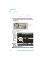
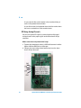
Required Equipment
• Agilent Infiniium 9000 Series oscilloscope.
• Two passive probes.
• Demo kit with demo board and USB cable.
Demo board connections:
MSO Cable
Connection
(Digital Inputs)
MODE Action
Select Knob
Power
or
Power is provided via
USB or MSO cable.
InfiniiMax
differential probe
Oscilloscope Probe Connections
4
Agilent Infiniium 9000 Series Oscilloscope Evaluation Guide
In This Guide
If you are experiencing the Infiniium 9000 Series oscilloscope for the first
time, begin with Lab 1, the Getting Started Guide. If you have a basic
knowledge of the Infiniium 9000 Series oscilloscope’s front-panel controls,
begin with Lab 2.
Topic
Page
Time
Allowance
Lab 1:
Getting Started
7
10 min.
Lab 2:
Viewing Complex Signals
22
10 min.
Lab 3:
Uncovering Signal Anomalies with
Responsive Deep Memory
26
10 min.
Lab 4:
InfiniiScan Triggering
29
5 min.
Lab 5:
Mixed-Signal Oscilloscope (MSO)
32
10 min.
Lab 6:
USB
36
10 min.
Lab 7:
2
IC
45
10 min.
Lab 8:
SPI
49
10 min.
Lab 9:
CAN
55
10 min.
Lab 10:
RS-232
57
10 min.
Lab 11:
Segmented Memory
61
10 min.
Lab 12:
Histograms
65
5 min.
67
10 min.
Appendix A: Using Trigger Holdoff to Synchronize
Acquisition/Display on Complex
Signals
Agilent Infiniium 9000 Series Oscilloscope Evaluation Guide
5
6
Agilent Infiniium 9000 Series Oscilloscope Evaluation Guide
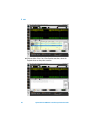
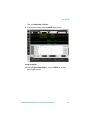
Agilent Infiniium 9000 Series Oscilloscopes
Evaluation Guide
1
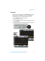
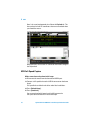
Getting Started
If you are not familiar with the Agilent Infiniium 9000 Series
oscilloscopes, please first look over the main sections of the front
panel as illustrated and then follow the exercises.
7
1
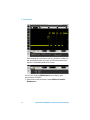
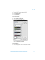
Getting Started
15" XGA touch screen
display
Drag-and-drop
measurements
Status tab shows
current settings
Mixed-signal oscilloscope
(MSO) cable connection
AutoProbe interface
8
Agilent Infiniium 9000 Series Oscilloscope Evaluation Guide
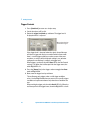
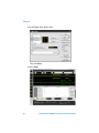
Getting Started
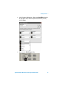
1
Selection knob, immediate action keys, and special menus
Push the knob to toggle selection
Run Control
Time/div and position
horizontal controls
Trigger level knob
and controls
Digital button for
mixed-signal
oscilloscope (MSO)
channels D0 – D15
Serial Decode button
for quick decode
access
Color-coded controls
for each oscilloscope
channel
USB ports
Agilent Infiniium 9000 Series Oscilloscope Evaluation Guide
9
1
Getting Started
Capturing and Viewing a Simple Signal
1 To power the demo board, connect a USB cable between it and the
Agilent Infiniium 9000 Series oscilloscope.
You can also apply power by connecting the oscilloscope’s MSO
cable to the demo board’s 40-pin connector.
2 Connect the scope channel 1 probe to demo board CH1 and GND.
3 Turn the SELECT switch to position 3 (Burst).
4 Press the [Default Setup] key on the front panel.
Press
The oscilloscope is now set in the default configuration. Because
the oscilloscope may have been used in a variety of applications by
a variety of people, it is a good measurement procedure to put the
oscilloscope in a known starting mode (Default Setup). This will
make it easy to duplicate measurements as no special conditions
will be set.
10
Agilent Infiniium 9000 Series Oscilloscope Evaluation Guide
Getting Started
1
5 Press [AutoScale].
The oscilloscope will analyze all active channels, turning them on
and setting the time base, V/div, and trigger conditions for an
initial display.
Agilent Infiniium 9000 Series Oscilloscope Evaluation Guide
11
1
Getting Started
Horizontal Control
1 Turn the large Horizontal scale knob clockwise and
counter-clockwise to control the time/div setting of the horizontal
axis. Observe the changes in the displayed signal. The current time
base setting is displayed in the lower middle of the screen.
2 Turn the small Horizontal position knob to move the waveform
horizontally from the trigger point. Push this knob to center (zero)
the trigger point.
Turn to control time/div
Turn to control
horizontal position
3 Set the time base to 1 ms/div.
4 Press the [Zoom] key.
5 Turn the
large
Horizontal
scale knob
counterclockwise
to make
the
window
on top
larger.
6 Press the
[Zoom]
key again
to return to the original display.
Note: At any time, to return to the original setup, press [AutoScale].
12
Agilent Infiniium 9000 Series Oscilloscope Evaluation Guide
Getting Started
1
Run Control
When the oscilloscope is turned on, or if [AutoScale] is pressed, the
acquisition will be set to [Run]. At any time, you may [Stop] the
acquisition process to examine a signal in detail or to save it.
1 Press [AutoScale] to return to simple setup.
2 Set the time base to 2 ms/div.
3 Press the [Single] key to make a single acquisition and stop the
acquisition process.
4 Use the large Horizontal scale knob to zoom in on the waveform.
Press for
single run
Agilent Infiniium 9000 Series Oscilloscope Evaluation Guide
13
1
Getting Started
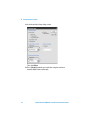
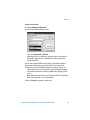
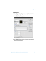
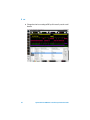
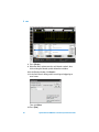
Acquisition Controls
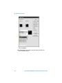
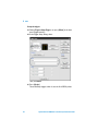
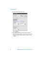
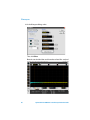
1 From the on-screen main menu, choose Setup>Acquisition....
Note the
sampling mode,
manual memory
depth,
averaging, and
manual
sampling rate
options.
2 Click Close.
14
Agilent Infiniium 9000 Series Oscilloscope Evaluation Guide
Getting Started
1
Vertical Controls
1 Press [AutoScale] to return to simple setup.
2 Turn the large
channel 1 (yellow)
Vertical scale knob to
control the V/div
setting.
The V/div setting is
displayed at the top
of the screen for
each channel.
Press
Knobs are color
coded to match the
waveform color.
Push the vertical
scale knob for vernier
fine adjustment.
3 Press the [1] key to
turn the channel off.
Press [1] again to
turn the channel on.
4 Turn the small
channel 1 (yellow)
Vertical position
knob to control the offset position of the waveform, moving it up or
down.
Agilent Infiniium 9000 Series Oscilloscope Evaluation Guide
15
1
Getting Started
Trigger Controls
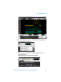
1 Press [AutoScale] to return to a simple setup.
2 Set the time base to 50 ns/div.
3 Rotate the trigger level knob up and down. The trigger level is
displayed while it is adjusted.
Move trigger level up
and down on signal
If the trigger level is above or below the signal, the oscilloscope
will force a trigger and display a waveform when in Auto mode.
Auto is a useful trigger mode to use when unsure of the exact
waveform, as activity will be displayed making it easy to better
configure the oscilloscope’s settings and trigger level.
When triggers are forced, the white Auto LED (in the Run Control
section) is lit. When the oscilloscope finds the trigger event, the
white Trig’d LED is lit.
4 Press the [Sweep] key in the trigger section to toggle from Auto
mode to Trig’d mode.
5 Now, move the trigger level up and down.
The oscilloscope only triggers when a valid trigger condition
exists. Use the Trig’d mode when you want to set a specific trigger
condition and capture waveforms only when those conditions are
met.
When waiting for trigger, only the white Arm’d LED is lit. When the
oscilloscope finds the trigger event, the white Trig’d LED is also lit.
16
Agilent Infiniium 9000 Series Oscilloscope Evaluation Guide
Getting Started
1
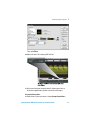
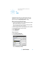
Making Measurements
The easiest way to make measurements is to drag-and-drop
measurement icons.
1 Press [AutoScale] to return to a simple setup.
2 Drag a measurement icon from the left-hand side of the screen to
a waveform.
3 When the icon border changes to the color of the desired
waveform, drop the icon.
Agilent Infiniium 9000 Series Oscilloscope Evaluation Guide
17
1
Getting Started
After dropping the measurement icon on a waveform, markers for
the measurement appear on screen, and the measurement data
appears in the bottom portion of the screen.
You can also set up the [Multi Purpose] key to display quick
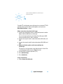
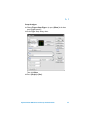
measurements. To do this:
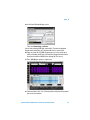
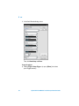
1 From the on-screen main menu, choose Utilities>Customize
Multipurpose....
18
Agilent Infiniium 9000 Series Oscilloscope Evaluation Guide
Getting Started
1
2 In the Customize Multipurpose dialog, select QuickMeas from the
top drop-down; then, select the quick measurements you want,
and click Close.
3 Now, press the [Multi Purpose] key.
Press
Agilent Infiniium 9000 Series Oscilloscope Evaluation Guide
19
1
Getting Started
The quick measurement data appears in the bottom portion of the
screen.
Note that the [Multi Purpose] key can also be customized to:
• QuickPrint — to print the screen image.
• QuickScreen — to save the screen image to a file.
• QuickSetup — to load a setup file.
• QuickWaveform — to save waveform data.
• QuickExecute — to run a program.
Using Markers
1 Press the [Markers] key on front panel. Horizontal (Ax and Bx)
and Vertical (Ay and By) markers can be positioned on the
waveform to measure time or volts of interest.
2 For example, in the Markers Setup dialog, select Manual
Placement from the drop-down, and click Close (or press
[Markers] again).
20
Agilent Infiniium 9000 Series Oscilloscope Evaluation Guide
1
Getting Started
3 Drag the Ax marker to the leading edge on the CH1 waveform.
4 Drag the Bx marker to the last edge on the CH1 waveform.
The bottom portion of the screen shows the values of each marker
and their deltas.
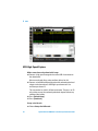
Saving Data, Setups, or Images
You can save images, waveform data, or setups to a variety of media
including the local hard drive or USB host ports.
From the on-screen main menu, choose File>Save> and then the
type of file you want to save.
You can also print to printers set up in the Windows operation system.
For online assistance, choose Help>Contents....
Agilent Infiniium 9000 Series Oscilloscope Evaluation Guide
21
Agilent Infiniium 9000 Series Oscilloscopes
Evaluation Guide
2
Viewing Complex Signals
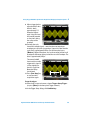
Video signals have been the ultimate display challenge for digitizing
oscilloscopes. These complex signals have long been considered the
display standard by which the display performance of digitizing
oscilloscopes have been compared to analog oscilloscope display
technology.
Video signals, due to their complexity, demand an oscilloscope with
high resolution, a fast display update rate, and a high sample rate to
avoid aliasing.
Make connections and perform initial setup:
1 To power the demo board, connect a USB cable between it and the
Agilent Infiniium 9000 Series oscilloscope.
2
3
4
5
6
7
You can also apply power by connecting the oscilloscope’s MSO
cable to the demo board’s 40-pin connector.
Connect the scope channel 1 probe to demo board CH1 and GND.
Turn the SELECT switch to position 0 (Video).
Remove the cap from the video camera lens.
Press [Default Setup].
Press [AutoScale].
Set the time base to 10 ms/div.
Set up the trigger:
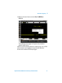
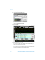
8 From the on-screen main menu, choose Trigger>Setup Trigger...
(or press [Menu] in the front panel Trigger controls).
9 In the Trigger Setup dialog, select:
22
Viewing Complex Signals
2
Then, click Close.
10 Adjust the volts/div setting to 500 mV/div.
11 Wave your hand over the demo board’s video camera lens to
observe the good display update rate of the oscilloscope.
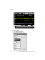
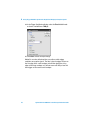
Set acquisition options:
12 From the on-screen main menu, choose Setup>Acquisition....
Agilent Infiniium 9000 Series Oscilloscope Evaluation Guide
23
2
Viewing Complex Signals
13 In the Acquisition Setup dialog, select:
Then, click Close.
14 Press [Single] to obtain one acquisition using the maximum
memory depth of the oscilloscope.
24
Agilent Infiniium 9000 Series Oscilloscope Evaluation Guide
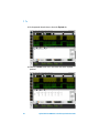
Viewing Complex Signals
2
15 Using the large Horizontal scale knob, adjust the time base setting
down to 2 µs/div to zoom in on the color burst.
Agilent Infiniium 9000 Series Oscilloscope Evaluation Guide
25
Agilent Infiniium 9000 Series Oscilloscopes
Evaluation Guide
3
Uncovering Signal Anomalies with
Responsive Deep Memory
An amplitude modulated (AM) signal is a very complex modulated
waveform where a high-definition display and deep memory are
needed for successful capture, viewing and analysis. In this lab, we
will capture an AM signal that includes an embedded anomaly (a
glitch). With the Infiniium 9000 Series MegaZoom technology, the
display system will clearly show this glitch while the deep memory
will allow us to zoom in for detailed analysis of the glitch after
capture.
Make connections and perform initial setup:
1 To power the demo board, connect a USB cable between it and the
Agilent Infiniium 9000 Series oscilloscope.
2
3
4
5
6
26
You can also apply power by connecting the oscilloscope’s MSO
cable to the demo board’s 40-pin connector.
Connect the scope channel 1 probe to demo board CH1 and GND.
Connect the scope channel 2 probe to demo board CH2 and GND.
Turn the SELECT switch to position 1 (AM).
Press [Default Setup].
Press [AutoScale].
Uncovering Signal Anomalies with Responsive Deep Memory
3
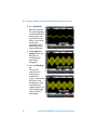
In this lab, a stable trigger is accomplished by triggering on the
synchronization signal on channel 2. In the absence of a
synchronization signal, trigger holdoff can be used to achieve a
stable trigger (see Appendix A).
7 Turn off the channel 2 display (still the trigger source) by pressing
the [2] key.
8 Re-adjust channel 1’s vertical scale to 500 mV/div and its vertical
position to 2.3 V offset to optimize viewing of the complex
channel 1 signal.
9 Set the time base to 100 µs/div.
Note that there is a glitch present in every other envelope.
10 Press [Single] to capture a single shot acquisition of this complex
waveform.
Press
Agilent Infiniium 9000 Series Oscilloscope Evaluation Guide
27
3
Uncovering Signal Anomalies with Responsive Deep Memory
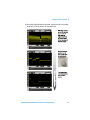
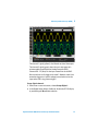
Take advantage of deep memory: zoom in on one of the glitches to see
the details:
Step 1: Using the small Horizontal position knob, move one of the
glitches to the center of the display.
Step 2: Using the large Horizontal time/div knob, set the time base to
500 ns/div (turn clockwise) to see characteristics of the glitch in
detail.
With up to 10 Mpts of deep memory you are able to see the big picture
(envelope of the entire AM signal) as well as zoom in on the details of
this anomaly while maintaining a high sample rate.
28
Agilent Infiniium 9000 Series Oscilloscope Evaluation Guide
Agilent Infiniium 9000 Series Oscilloscopes
Evaluation Guide
4
InfiniiScan Triggering
Capturing infrequent or hard to describe anomalies such as random
glitches requires oscilloscopes with innovative technology.
InfiniiScan is a software-based post-processing technology that
makes it easy to isolate anomalies.
This lab requires an InfiniiScan option license.
Make connections and perform initial setup:
1 To power the demo board, connect a USB cable between it and the
Agilent Infiniium 9000 Series oscilloscope.
2
3
4
5
6
7
You can also apply power by connecting the oscilloscope’s MSO
cable to the demo board’s 40-pin connector.
Connect the scope channel 1 probe to demo board CH1 and GND.
Make sure all other probes are disconnected from the
oscilloscope.
Turn the SELECT switch to position 3 (Burst).
Press [Default Setup].
Press [AutoScale].
Set the time base to 1 µs/div.
Set up the trigger:
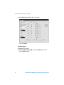
8 From the on-screen main menu, choose Trigger> InfiniiScan... (or
press [Menu] in the front panel Trigger controls).
9 In the Trigger Setup dialog, select:
29
4
InfiniiScan Triggering
Then, click Close.
10 In the waveform area, draw a box around the area where an
occasional glitch occurs.
30
Agilent Infiniium 9000 Series Oscilloscope Evaluation Guide
InfiniiScan Triggering
4
11 Release the mouse button and select Zone 1>AND Must
Intersect.
The oscilloscope now triggers and captures only waveforms
where the glitch occurs.
InfiniiScan can be extremely effective in isolating cycles such as DDR
reads and writes, or in triggering on events that are difficult to
describe with traditional oscilloscope triggers.
Agilent Infiniium 9000 Series Oscilloscope Evaluation Guide
31
Agilent Infiniium 9000 Series Oscilloscopes
Evaluation Guide
5
Mixed-Signal Oscilloscope (MSO)
In mixed analog and digital designs, it is often important to view
multiple analog and digital channels, which is significantly beyond the
capability of a 2- or 4-channel oscilloscope. With 2 or 4 oscilloscope
channels plus 16 logic timing channels, the unique 2+16 or 4+16
channel Mixed Signal Oscilloscope (MSO) affords the opportunity to
view more signals and to make time-correlated measurements across
all channels.
Make connections and perform initial setup:
1 Connect the MSO cable between the oscilloscope and the demo
board’s 40-pin connector.
This powers the demo board and probes its digital signals.
2
3
4
5
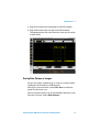
6
32
Normally, you would use flying leads to probe digital signals in
your device under test (DUT). The demo board 40-pin connector
was designed with built-in terminations.
Connect the scope channel 1 probe to demo board CH1 and GND.
Connect the scope channel 2 probe to demo board CH2 and GND.
Turn the SELECT switch to position 4 (DAC).
Press [Default Setup].
Press [AutoScale].
5
Mixed-Signal Oscilloscope (MSO)
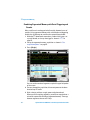
The channel 1 signal (yellow) is the filtered version of the output.
The channel 2 signal (green) shows the stair-step output of a
microcontroller-based Digital-to-Analog Converter (DAC).
Channels D0 – D7 (blue) are the input control lines to the DAC.
We were able to easily trigger on channel 2. However, what if we
wanted to trigger on a specific voltage instruction based on the
input to the DAC using pattern trigger?
Set up digital channels:
7 From the on-screen main menu, choose Setup>Digital....
8 In the Digital Setup dialog’s Enable tab, disable the D7-D0 display
by unchecking the D7-0 enable selection.
Agilent Infiniium 9000 Series Oscilloscope Evaluation Guide
33
5
Mixed-Signal Oscilloscope (MSO)
9 In the Digital Setup dialog’s Bus 1 tab, select:
Then, click Close.
Set up the trigger:
To trigger on a bus value:
10 Choose Trigger>Setup Trigger... (or press [Menu] in the front
panel Trigger controls).
34
Agilent Infiniium 9000 Series Oscilloscope Evaluation Guide
Mixed-Signal Oscilloscope (MSO)
5
11 In the Trigger Setup dialog, select:
Then, click Close.
12 Set the time base to 20 µs/div.
At center screen, notice the Bus 1 value.
Agilent Infiniium 9000 Series Oscilloscope Evaluation Guide
35
Agilent Infiniium 9000 Series Oscilloscopes
Evaluation Guide
6
USB
Agilent offers a USB compliance package as well as a USB protocol
triggering and decode application. The compliance package tests for
signal conformance to USB-IF industry standard while the protocol
triggering and decode application targets rapid debug.
For this exercise, a USB protocol application option license is
required.
USB is a differential serial bus and can run at low-, full-, or high-speed
data rates. Example devices for each:
Data rate
Devices
Required probes
Low speed (1.5 Mbps)
USB mouse or USB keyboard
2 single-ended
Full speed (12 Mbps)
Older USB hub
2 single-ended
High-speed(480 Mbps) Current thumb drives or USB
mass storage
1 differential
This lab includes examples from each speed category.
USB Low-Speed Capture
Make connections and perform initial setup:
1 Connect the demo board USB-B port to your 9000 Series
oscilloscope using a USB A to B cable.
2 Plug mouse into USB-A port on the lower right side of the demo
board.
The mouse will create USB low-speed traffic that the scope probes
will monitor.
3 Connect the scope channel 1 probe to demo board D+ probe loop
and GND (on the right-side of the demo board).
36
6
USB
4 Connect the scope channel 2 probe to demo board D- probe loop
5
6
7
8
and GND.
Remove all other probes and connections.
If you have the MSO cable connected to the demo board’s 40-pin
connector, turn the SELECT switch to position 0 (so digital
channels aren’t captured).
Press [Default Setup].
Press [AutoScale].
You are now viewing low-speed serial traffic between a mouse and
the PC in the oscilloscope.
9 Set the time base to 20 µs/div to see a single packet.
Move the mouse and you can see additional traffic.
Set up serial decode:
10 Choose Setup>Serial Decode....
11 In the Serial Decode dialog, select:
Then, click Auto Setup and Close.
Agilent Infiniium 9000 Series Oscilloscope Evaluation Guide
37
6
USB
Here’s the associated protocol view. Select the Payload tab. The
data packets include X-Y coordinates that were transmitted when
you moved the mouse.
Move the mouse and see the X-Y coordinate information change in
the Payload tab.
USB Full-Speed Capture
Make connections and perform initial setup:
12 Disconnect the mouse from the demo board USB-A port.
13 Connect a full-speed device to the USB-A connector on the demo
board.
Full speed hubs or older thumb drives make ideal candidates.
14 Press [Default Setup].
15 Press [AutoScale].
You are now viewing full-speed serial traffic between the
full-speed device and the PC in the oscilloscope.
38
Agilent Infiniium 9000 Series Oscilloscope Evaluation Guide
6
USB
Set up serial decode:
16 Choose Setup>Serial Decode....
17 In the Serial Decode dialog, select:
Then, click Auto Setup and Close.
Auto Setup sets the sample rate, memory depth, measurement
thresholds, trigger levels, and holdoff to correctly decode the
specified protocol.
You are now viewing USB full speed traffic. To make the protocol
decode more interesting, let’s watch traffic that is more varied.
18 Copy any large file (a 100M file generates about 2 minutes of
traffic works well) from a thumb drive (+full speed hub) plugged
into the demo board to the Infiniium 9000 Series desktop (or vice
versa).
Note: Most new thumb drives are high speed USB. To convert the
traffic into full speed, use a full speed hub.
19 Press [Single] to capture a single trace.
Agilent Infiniium 9000 Series Oscilloscope Evaluation Guide
39
6
USB
20 Click on either a Data 1 or a Data 0 packet row; then, select the
Payload tab to see the packet contents.
40
Agilent Infiniium 9000 Series Oscilloscope Evaluation Guide
USB
6
Set up the trigger:
21 Choose Trigger>Setup Trigger... (or press [Menu] in the front
panel Trigger controls).
22 In the Trigger Setup dialog, select:
Then, click Close.
23 Press [Single] and note that the oscilloscope triggers when it
sees the first DATA0 packet.
Agilent Infiniium 9000 Series Oscilloscope Evaluation Guide
41
6
USB
USB High-Speed Capture
Make connections and perform initial setup:
24 Connect a high speed storage device to the USB-A connector on
the demo board.
Most recent thumb drives make excellent devices for this.
25 Connect an InfiniiMax differential probe with socketed probe head
adapter to the demo board’s USB high-speed connector. Use
oscilloscope channel 3.
This connection has built-in 82 ohm termination. The posts are 20
mil and they accept the socketed probe head adapter without any
additional termination.
26 Press [Default Setup].
27 Press [AutoScale].
Set up serial decode:
28 Choose Setup>Serial Decode....
42
Agilent Infiniium 9000 Series Oscilloscope Evaluation Guide
6
USB
29 In the Serial Decode dialog, select:
Then, click Auto Setup and Close.
You are now viewing USB high speed traffic. To make the protocol
decode more interesting, let’s watch traffic that is more varied.
30 Copy any large file (a 100M file generates just a few seconds of
traffic and works well) from a thumb drive plugged into the demo
board to the Infiniium 9000 Series desktop (or vice versa).
31 Press [Single] to capture a single trace.
32 Click on either a Data 1 or a Data 0 packet and click on the payload
tab to see the contents.
Agilent Infiniium 9000 Series Oscilloscope Evaluation Guide
43
6
USB
Set up the trigger:
33 Choose Trigger>Setup Trigger... (or press [Menu] in the front
panel Trigger controls).
34 In the Trigger Setup dialog, select:
Then, click Close.
35 Press [Single].
The oscilloscope triggers when it sees the first DATA0 packet.
44
Agilent Infiniium 9000 Series Oscilloscope Evaluation Guide
Agilent Infiniium 9000 Series Oscilloscopes
Evaluation Guide
7
I 2C
To enable I2C serial decode, your oscilloscope has to have the I2C/SPI
protocol option installed. (The installed options are listed in the
Help>About Infiniium... dialog.)
Make connections and perform initial setup:
1 To power the demo board, connect a USB cable between it and the
Agilent Infiniium 9000 Series oscilloscope.
You can also apply power by connecting the oscilloscope’s MSO
cable to the demo board’s 40-pin connector.
2 Connect the scope channel 1 probe to demo board CH3 (SCL) and
GND.
3 Connect the scope channel 2 probe to demo board CH4 (SDA) and
GND.
4 Make sure all other probes are disconnected from the
oscilloscope.
This exercise can also be done using digital channels 14 and 15 or
a combination of oscilloscope and digital channels.
5 Turn the SELECT switch to position 5 (I2C).
6 Press [Default Setup].
7 Press [AutoScale].
Set up serial decode:
8 Choose Setup>Serial Decode....
45
7
I2 C
9 In the Serial Decode dialog, select:
Then, click Auto Setup and Close.
10 Press [Single].
11 Set the time base to 1 ms/div.
As you move the blue vertical marker in the waveform display, it
tracks in the protocol viewer window.
As you click on rows in the protocol viewer, the blue marker shows
the exact associated time in the waveform menu.
46
Agilent Infiniium 9000 Series Oscilloscope Evaluation Guide
I2C
7
Set up the trigger:
12 Choose Trigger>Setup Trigger... (or press [Menu] in the front
panel Trigger controls).
13 In the Trigger Setup dialog, select:
Then, click Close.
14 Press [Single] or [Run].
Agilent Infiniium 9000 Series Oscilloscope Evaluation Guide
47
7
I2 C
15 In the protocol decode viewer, select the Payload tab.
16 Select the Header tab to see a data sheet view of the acquired
protocol.
48
Agilent Infiniium 9000 Series Oscilloscope Evaluation Guide
Agilent Infiniium 9000 Series Oscilloscopes
Evaluation Guide
8
SPI
To enable SPI serial decode, your oscilloscope has to have the I2C/SPI
option installed. (The installed options are listed in the Help>About
Infiniium... dialog.)
Make connections and perform initial setup:
1 Connect the MSO cable between the oscilloscope and the demo
board’s 40-pin connector.
This powers the demo board and probes its digital signals.
2
3
4
5
Normally, you would use flying leads to probe digital signals in
your device under test (DUT). The demo board 40-pin connector
was designed with built-in terminations.
Disconnect all oscilloscope probes from the demo board. This is a
digital signal only demo.
Turn the SELECT switch to position 6 (SPI).
Press [Default Setup].
Press [AutoScale].
Set up serial decode:
6 Choose Setup>Serial Decode....
49
8
SPI
7 In the Serial Decode dialog, select:
Then, click Auto Setup and Close.
Set up the trigger:
8 Choose Trigger>Setup Trigger... (or press [Menu] in the front
panel Trigger controls).
50
Agilent Infiniium 9000 Series Oscilloscope Evaluation Guide
SPI
8
9 In the Trigger Setup dialog, select:
Then, click Close.
10 Change the time base setting to 500 µs/div to easily see the serial
decode.
Agilent Infiniium 9000 Series Oscilloscope Evaluation Guide
51
8
SPI
As you move the blue vertical marker in the waveform display, it
tracks in the protocol viewer window.
As you click on rows in the protocol viewer, the blue marker shows
the exact associated time in the waveform menu.
SPI Using Analog Channels
You can also capture SPI signals by connecting the oscilloscope’s
analog channels to the proper signals on the demo board’s 40-pin
connector.
Make connections and perform initial setup:
1 To power the demo board, connect a USB cable between it and the
Agilent Infiniium 9000 Series oscilloscope.
2 Connect the scope analog channel probes to pins on the demo
board’s 40-pin connector:
52
Agilent Infiniium 9000 Series Oscilloscope Evaluation Guide
SPI
8
3 Turn the SELECT switch to position 6 (SPI).
4 Press [Default Setup].
5 Press [AutoScale].
Set up serial decode:
6 Choose Setup>Serial Decode....
7 In the Serial Decode dialog, select:
Then, click Auto Setup and Close.
Set up the trigger:
8 Set up the trigger the same as in the previous section.
Agilent Infiniium 9000 Series Oscilloscope Evaluation Guide
53
8
SPI
9 Change the time base setting to 500 µs/div to easily see the serial
decode.
54
Agilent Infiniium 9000 Series Oscilloscope Evaluation Guide
Agilent Infiniium 9000 Series Oscilloscopes
Evaluation Guide
9
CAN
To enable CAN serial decode, your oscilloscope has to have the
CAN/FlexRay serial bus protocol option installed. (The installed
options are listed in the Help>About Infiniium... dialog.)
Make connections and perform initial setup:
1 To power the demo board, connect a USB cable between it and the
Agilent Infiniium 9000 Series oscilloscope.
2
3
4
5
You can also apply power by connecting the oscilloscope’s MSO
cable to the demo board’s 40-pin connector.
Connect the scope channel 1 probe to demo board CH1 and GND.
Turn the SELECT switch to position 8 (CAN).
Press [Default Setup].
Press [AutoScale].
Set up serial decode:
6 Choose Setup>Serial Decode....
7 In the Serial Decode dialog, select:
Then, click Auto Setup and Close.
55
9
CAN
8 Press [Single].
9 Move the mouse pointer over the serial decode symbols; then,
click and drag the decode symbols below the waveform.
10 In the Decode window, click Search....
11 In the Serial Search dialog, enable searching and triggering on
error frames:
Then, click Close.
12 Press [Run].
56
Agilent Infiniium 9000 Series Oscilloscope Evaluation Guide
Agilent Infiniium 9000 Series Oscilloscopes
Evaluation Guide
10
RS-232
The RS-232/UART serial triggering and decode option displays
responsive, time-aligned, on-screen decode of RS-232 and other
UART serial buses. It provides triggering capabilities on specified
transmit or receive values, as well as on parity errors.
To enable RS-232/UART serial decode, your oscilloscope must have
the RS-232 option installed. (The installed options are listed in the
Help>About Infiniium... dialog.)
Make connections and perform initial setup:
1 To power the demo board, connect a USB cable between it and the
Agilent Infiniium 9000 Series oscilloscope.
2
3
4
5
6
You can also apply power by connecting the oscilloscope’s MSO
cable to the demo board’s 40-pin connector.
Connect the scope channel 1 probe to demo board CH1 and GND.
Connect the scope channel 2 probe to demo board CH2 and GND.
Turn the SELECT switch to position 7 (RS-232).
Press [Default Setup].
Press [AutoScale].
57
10 RS-232
Set up serial decode:
7 Choose Setup>Serial Decode....
8 In the Serial Decode dialog, select:
58
Agilent Infiniium 9000 Series Oscilloscope Evaluation Guide
RS-232
10
Then, click Auto Setup and Close.
9 In the Decode window, select the ASCII display format.
Set up the trigger:
10 Choose Trigger>Setup Trigger... (or press [Menu] in the front
panel Trigger controls).
Agilent Infiniium 9000 Series Oscilloscope Evaluation Guide
59
10 RS-232
11 In the Trigger Setup dialog, select:
Then, click Close.
12 Press [Run].
60
Agilent Infiniium 9000 Series Oscilloscope Evaluation Guide
Agilent Infiniium 9000 Series Oscilloscopes
Evaluation Guide
11
Segmented Memory
Agilent’s segmented memory feature can optimize your oscilloscope’s
acquisition memory, allowing you to capture more selective signal
details with less memory and then easily view all captured waveforms
and scroll through each individual waveform segment.
Make connections and perform initial setup:
1 To power the demo board, connect a USB cable between it and the
Agilent Infiniium 9000 Series oscilloscope.
2
3
4
5
6
7
8
9
You can also apply power by connecting the oscilloscope’s MSO
cable to the demo board’s 40-pin connector.
Connect the scope channel 1 probe to demo board CH1 and GND.
Connect the scope channel 2 probe to demo board CH2 and GND.
Connect the MSO cable between the oscilloscope and the demo
board’s 40-pin connector.
Turn the SELECT switch to position 6 (SPI).
Press [Default Setup].
Press [AutoScale].
Set the time base to 1 ms/div.
Press [Single].
Set acquisition options:
10 From the on-screen main menu, choose Setup>Acquisition....
61
11 Segmented Memory
11 In the Acquisition Setup dialog, select:
Then, click Close.
12 Press [Single] to capture the desired number of segments.
After the acquisition completes, notice the bottom portion of the
screen has a tab for navigating through the segmented memory
waveforms.
62
Agilent Infiniium 9000 Series Oscilloscope Evaluation Guide
Segmented Memory
11
13 Use the forward, back, start, and end buttons to play through the
acquired segments one by one.
14 Enter a play rate of 100 ms, and click Play to play back all the
captured segments.
Note that time tags are kept for each segment.
Agilent Infiniium 9000 Series Oscilloscope Evaluation Guide
63
11 Segmented Memory
Combining Segmented Memory with Serial Triggering and
Decode
Many serial buses have long periods of inactivity between bursts of
packets. Using segmented memory with serial decode and triggering
enables the oscilloscope to maximize the captured time window.
1 Make the I2C demo board connections, perform initial setup, set
up serial decode, and set up the trigger as shown in “I2C" on
page 45.
2 Set up the segmented memory acquisition as shown in “Set
acquisition options:" on page 61.
3 Press [Single].
You can see the number of segments acquired in upper left portion
of the screen.
4 Part way through the acquisition, disconnect power to the demo
board to stop I2C traffic.
5 Wait a minute, and then re-apply power to the demo board.
When you finish acquiring segments, you will have acquired over a
minute of capture with the help of segmented memory. Time tags
between segments time out at 6.5 days.
64
Agilent Infiniium 9000 Series Oscilloscope Evaluation Guide
Agilent Infiniium 9000 Series Oscilloscopes
Evaluation Guide
12
Histograms
Histograms give you an easy way to evaluate statistics associated
with waveforms. The low-cost demo board produces noise that
appears as thick traces for any oscilloscope that captures its signals.
Use a histogram to measure the amount of this noise.
Make connections and perform initial setup:
1 To power the demo board, connect a USB cable between it and the
Agilent Infiniium 9000 Series oscilloscope.
2
3
4
5
6
7
8
9
You can also apply power by connecting the oscilloscope’s MSO
cable to the demo board’s 40-pin connector.
Connect the scope channel 1 probe to demo board CH1 and GND.
Make sure all other probes are disconnected from the
oscilloscope.
Turn the SELECT switch to position 7 (RS-232).
Press [Default Setup].
Press [AutoScale].
Adjust the horizontal position to -300 ns.
Set the time base to 50 ns/div.
Adjust the channel 1 vertical scale to 500 mV/div.
Set up the histogram:
10 From the on-screen main menu, choose Analyze>Histogram....
65
12 Histograms
11 In the Histogram dialog, select:
Then, click Close.
Note the standard deviation and the number of total hits analyzed.
66
Agilent Infiniium 9000 Series Oscilloscope Evaluation Guide
Agilent Infiniium 9000 Series Oscilloscopes
Evaluation Guide
A
Using Trigger Holdoff to Synchronize
Acquisition/Display on Complex
Signals
Triggering on simple repetitive signals is easy using standard edge
triggering. But if you need to synchronize your oscilloscope’s
acquisitions/display on more complex signals, such as an
amplitude-modulated signal, you will need to use your oscilloscope’s
trigger hold-off capability unless there is an external synchronization
signal available. This lab shows you how to use trigger holdoff to
achieve a stable trigger in the absence of a synchronization signal.
Make connections and perform initial setup:
1 To power the demo board, connect a USB cable between it and the
Agilent Infiniium 9000 Series oscilloscope.
2
3
4
5
You can also apply power by connecting the oscilloscope’s MSO
cable to the demo board’s 40-pin connector.
Connect the scope channel 1 probe to demo board CH1 and GND.
Make sure all other probes are disconnected from the
oscilloscope.
Turn the SELECT switch to position 1 (AM).
Press [Default Setup].
67
A
Using Trigger Holdoff to Synchronize Acquisition/Display on Complex Signals
6 Press [AutoScale].
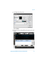
Note that AutoScale
sets up the triggering
and horizontal display
based on the carrier
signal. However, our
desire is to set up the
oscilloscope’s
triggering based on
the envelope of this
complex AM signal.
7 Change time base
setting to 100 µs/div.
Note that the
oscilloscope will
appear to be
untriggered.
8 Press the [Run/Stop]
key.
This will stop
acquisitions and
display the last
acquisition on
screen—the expected
AM signal is now
displayed on a single
acquisition when
stopped. Now let’s set
up the holdoff trigger
value to achieve a
stable trigger.
68
Agilent Infiniium 9000 Series Oscilloscope Evaluation Guide
A
Using Trigger Holdoff to Synchronize Acquisition/Display on Complex Signals
9 Adjust trigger level to
approximately 3 volts,
which is down
approximately 1/3
below the highest
peak. Using this level
will provide potential
re-arm times during
the valleys of the
envelope.
10 Estimate the cycle
time of this complex signal – note that there are two unique
envelopes per cycle time (use markers if you wish). Note that the
cycle time is approximately 450 µs. On the front panel, press
[Markers], Manual Placement, and set Ax to top of peak of small
envelope and Bx to top of the peak of the next small envelope. The
delta is approximately 450 µs.
The correct holdoff
time to achieve stable
trigger on this signal is
a value slightly less
than this cycle time.
Note that 400 µs
should work.
11 Press [Run/Stop] key
to start unstable
acquisitions again.
Set up the trigger:
12 From the on-screen main menu, choose Trigger>Setup Trigger...
(or press [Menu] in the front panel Trigger controls).
13 In the Trigger Setup dialog, click Conditioning....
Agilent Infiniium 9000 Series Oscilloscope Evaluation Guide
69
A
Using Trigger Holdoff to Synchronize Acquisition/Display on Complex Signals
14 In the Trigger Conditioning dialog, select the Fixed holdoff mode
and enter a holdoff time of 400 µs.
15 Click Close to close the open dialogs.
Holdoff is an under-utilized tool that can achieve stable trigger
conditions on complex signals. The idea is that the trigger will arm on
the first edge of the small envelope and will then ignore the rising
edges of the large envelope as it will not rearm until 400 µs later and
then trigger on the second small envelope.
70
Agilent Infiniium 9000 Series Oscilloscope Evaluation Guide
PC31
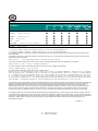
␜ᵄེ㒝ઙ OSCILLOSCOPE ACCESSORY
ㇱઙฬ⒓
Part Name
Machined parts
Connectors
Cables
Metal chassis and panels
Metal fasteners
Printed circuit assemblies
Other parts
Ქኂ‛凝
Ქኂ‛凝ᚗర⚛
Toxic or Hazardous Substances and Elements
卋
Pb
ᳮ
Hg
叏
Cd
ચ卲
卲
ચ
Cr6+
ᄙᄽ侶⧶
ᄽ侶⧶
PBB
ᄙᄽੑ⧶ㅘ
ੑ⧶ㅘ
PBDE
}
}
´
´
´
´
}
}
}
}
}
}
}
}
}
´
}
}
}
´
}
´
´
}
´
}
}
}
}
}
}
}
}
}
}
}
}
}
}
}
}
}
O: !"#$%&'(" SJ/T))363-2006 *+,.&1(45789
X: ;<
=>"#$%&'(?@SJ/T))363-2006 *+,.&1(459
O: Indicates that this toxic or hazardous substance contained in all of the homogeneous materials for this part is below the limit requirement in
SJ/T11363-2006.
X: Indicates that this toxic or hazardous substance contained in at least one of the homogeneous materials used for this part is above the limit
requirement in SJ/T11363-2006.
ABDEFGH>IKLNQR&UFVWYZF[DE\%]^_`R&gj&k9
If more than one table is shown above, reference your order or packing list to determine which is applicable to your product.
qRv4wxyzgj&{g|}~KLR&
9
If you have a question about the manufacturing date for your product, ask your Agilent representative
yA&~KLNQgj9
For Agilent contact information, please reference your product manual.
%~gj&,.Kzgj*w ¡}1&¢£9¢£¤¥zgj¦§¨
©ª
8&«¬&®K¨©ª
gjD¯@w°±&,.²°9¢£³´&&µ¶·¸N
Q¹º»¼½¾º¿¡zgj ¡}1À}ÁÂHÃÄ9 ¡}1»Å¿¡V¡Æ9 ¡}1¢£»ÇÈÅÉÊ&¿
¡¹ºË»ÌÍgj
Îy&ÅÏÐÅÑ´Òª
9R&gjÓÔÕ'>ÖÓ×Ø&Ù
ÚÕÛܶÐÝÐÞ*Ð
VWßàáâ&gjãKäå& ¡}1ægjzç& ¡}1è9¥HéÖáâ&Ù
* ê
ëì}1¢£Kzç*&EFUPð&ñòóK¥áâ&gj& ¡}1ôÅõö÷»øÅùÅ9
In accordance with the requirements of China’s Administrative Measure on the Control of Pollution Caused by Electronic Information Products (the
“Measure”), Agilent has labeled this product with a number identifying its Environment-Friendly Use Period (“EFUP") This number reflects an
estimate of the expected life of the product under the normal use and operating conditions as defined in the product user manual which is
distributed with the product. Use of the number is only for purposes related to the Measure and does not imply or guarantee that the product is
free from defects prior to the EFUP expiration date. No warranties or guarantees are implied by use of the EFUP number. Use of the EFUP
number does not alter any warranties found in, nor affect in any way, the terms and conditions associated with the purchase of this product.
Your Agilent product may contain replaceable assemblies/components (including disk drive, power supply, mouse, display, or battery, which are
not manufactured by Agilent) which have a shorter EFUP number than that which is indicated on the product itself. In cases where the assembly,
component, or part is labeled with an EFUP which differs from the one indicated by Agilent, the EFUP on the assemblies/component or part takes
precedence. Agilent makes no claims concerning, and takes no responsibility for the EFUP numbers reflected on goods which are not
manufactured by Agilent.
Revision: C
www.agilent.com
Agilent Technologies, Inc. 2009
Printed in U.S.A.
Third edition, August 2009
*N2918-97003*
N2918-97003