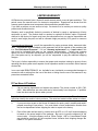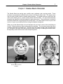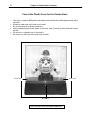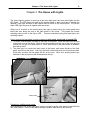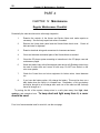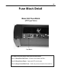
1
i
®
Buzz E. Smoke Alarm and House of Hazards™
Operating Manual
Version 2.3
ii
Buzz E. Smoke Alarm and House of Hazards™
Operating Manual
Congratulations
on your purchase of a ROBOTRONICS, Inc. Smoke
Alarm with House of Hazards. Your house and robot have been carefully
constructed of the highest quality components. Its design is the result of years of
experience building safety education products. You will find it an extremely
effective educational tool for your organization. It is built for ease of operation,
maintenance and repair. It is built so that you can easily expand its functions
making its usefulness grow as your needs grow.
Please read this manual carefully. It will help you make the most of your
Smoke Alarm and House. Attention to maintenance will greatly prolong the life of
this product. Most problems you encounter will be minor and the manual will
provide an answer. Please feel free to contact us if you have unanswered questions
relating to operation, maintenance, and repair. Also, if you have technical
questions relating to expanding the functions of the House or Smoke Alarm, we
would be very happy to help.
Sincerely,
ROBOTRONICS, Inc.
ROBOTRONICS INC.
Springville, Utah 84663
www.Robotronics.com
© Robotronics Inc., 2000.
All Rights Reserved.
Printed in USA
Contents
Contents
Warranty Information.......................................................................................... 1
PART 1 General Operating Instructions ..................................... 3
Chapter 1 Getting Started ...........................................................3
Operating Hints ......................................................................................... 3
Setup and How To Operate ...................................................................... 4
Transporting .............................................................................................. 5
PART 2 Subsystems of the Smoke Alarm & House .............. 6
Chapter 2 Automatic Music Control System .............................6
Chapter 3 Smoke Alarm Character ............................................7
Chapter 4 The House with Lights..........................................9,10
Chapter 5 CD Player ..................................................................11
Chapter 6 Power Supply ...........................................................13
PART 3 Optional Features ................................................................ 14
Chapter 7 Control Box ..............................................................14
Chapter 8 Voice System – Headset Microphone.....................15
Chapter 9 Video Camera and Monitor ......................................... 16
Chapter 10 Voice Modifier ..........................................................17
Chapter 11 Battery Option ..........................................................19
Battery Charger .............................................................................20
PART 4 Maintenance ........................................................................... 22
Chapter 12 Maintenance ...........................................................22
Regular Maintenance Checklist .............................................................. 22
Painting of the Body ................................................................................ 24
Repair of the Body .................................................................................. 25
Storage.................................................................................................... 26
iii
iv
Contents
Appendixes
Appendix A Robot Parts Identification .....................................27
Smoke Alarm Inside View ....................................................................... 28
Smoke Alarm Back View ......................................................................... 29
Servo Board ......................................................................................... 30
Base Unit Electronics .............................................................................. 31
House Back Inside View ......................................................................... 32
Switching Output Boards......................................................................... 33
Operator Control Box Inside.................................................................... 34
Fuse Block Detail .................................................................................... 35
Notes Section* .................................................................................................... 36
Technical Tips Section* ...................................................................................... 37
* These sections can be used to place additional notes that you would like to record, during
your use of the House or additional information sent from Robotronics.
Warranty Information and Getting Help
1
LIMITED WARRANTY
All Robotronics products have a limited 6 month warranty which covers all parts and labor. This
period covers the normal burn-in for electronic components. Experience has shown that this
warranty period catches most component defects and other possible flaws.
If you have a problem, we are anxious to help. Our desire is to be certain you receive a quality
product and excellent service.
Warranty work is specifically limited to correction of defects by repair or replacement of faulty
equipment or parts. The product shall be repaired or replaced at Seller's option. Equipment
returned to the factory for repair must have pre-authorization from our service department and
must be sent freight pre-paid, and will be returned freight pre-paid by UPS ground or common
carrier.
For international shipments, you will be responsible for paying customs duties, taxes and other
fees. The shipment must be labeled on the paperwork and on the outside of the container that
it is “For Educational Purposes”. If it is a “warranty replacement” or a “repair return” this
also must be indicated both ways on the customs documentation. Contact your customs
agency on how to document the shipment correctly to avoid unnecessary customs charges. If
you need parts sent by air shipment you will be responsible to pay the additional shipping
charges.
The buyer is further responsible to ensure that proper and complete training be given to those
operating the robot system as all aspects of such operation cannot be covered in a brief manual
such as this.
In no event shall ROBOTRONICS, Inc. be liable for any incidental or consequential damages in
connection with or arising from the use of the robot or arising from the use of this manual or any
procedures contained herein.
If You Have A Problem
1.
Call our service department and explain the problem. The phone number is (801) 7984466. Most difficulties are minor and can be solved easily over the phone. If possible,
have the robot near the phone when you call.
Important:
Have the robot serial number and model number ready. This will help our
technician identify the model of robot you have. The serial and model number sticker is located
2.
If you must return a part or the House of Hazards for repair, pack it carefully and send it
prepaid according to instructions. You must obtain a return authorization number from
the service department before shipping the robot or a part to the factory.
3.
Parts of the robot are best sent by a carrier such as UPS, or U.S. mail, because shipping
is based on the actual weight of the package. Be sure to insure the shipment for the
correct value. A freight company such as Yellow Freight , ABF or Consolidated Freight
way should be used only for the complete House, because their shipping charges are
based on 100 pound minimums.
2
4.
Warranty Information and Getting Help
For international shipments, you will be responsible for paying customs duties, taxes and
other fees. The shipment must be labeled on the paperwork and on the outside of the
container that it is “For Educational Purposes”. If it is a “warranty replacement” or a
“repair return” this also must be indicated both ways on the customs documentation.
Contact your customs agency on how to document the shipment correctly to avoid
unnecessary customs charges.
After The Warranty Repair and Help
Our technical staff is always available to help with your questions. Again, most problems are
easily solved. If you do need replacement parts, we can usually ship them the following day you
call. Please call our service department for a return authorization number before sending a part
or your robot in for repair or modifications.
Because of parts availability, robots may vary slightly from unit to unit. If you have any
questions, please contact our service department. The service department phone number is:
(801) 489-4466.
Chapter 1 Getting Started: Operating Hints
3
Part 1 General Operating Instructions
CHAPTER 1 Getting Started
DESCRIPTION OF FEATURES AND OPERATING HINTS
Robotronics’ new animated Smoke Alarm and House of Hazards are unique and exciting tools
for teaching fire prevention and life-safety education. In the hands of a skilled and trained
operator, the Smoke Alarm can be very effective in getting your safety messages across to
children and adults.
There are two versions of the House of Hazards. Both versions have the animated Smoke
Alarm character with moving eyes, eyelids, eyebrows, and arms. Both versions also have the
Automatic Music Control System. The deluxe model includes a control box that enables the
operator to manually initiate all of the functions of both the smoke alarm and the house. A
headset microphone with a two-way voice system allows you to communicate through the
smoke alarm. A voice modifier is also available which allows you to disguise the sound of your
voice. This manual covers both versions so that if you want to add the control box and/or the
house at some point you will have all of the information that you need.
In automatic mode, the Smoke Alarm has a personality of his own. In manual mode you can
add a personal touch to the character as you interact with your audience. Much of the
excitement of the Smoke Alarm is provided by the operator. The selection and training of the
operator should be done carefully, so as to provide a person with good judgment and an
outgoing personality. Nevertheless, with a little practice anyone can learn to operate it and
even those with a shy personality can be very effective using the Smoke Alarm and House.
When operating in crowds, always have a trained person posted near the House to help in
crowd control, and to protect it from vandalism. This person is also available to answer
questions and interact with the Smoke Alarm. With a little practice, the person and the Smoke
Alarm can come up with effective ways to interact during a program. For example the person
can present safety rules and the Smoke Alarm can be called on to test the children on what they
have learned. This will greatly re-enforce what they have learned.
The Smoke Alarm can be a highly successful tool for safety education and entertainment.
Appropriate jokes, stories and general conversation can be very effective. Children of all ages
will be strongly attracted to it. They will talk to it, and generally treat it as a good friend.
The most important ingredient to the use and effective operation of the Smoke Alarm system is
common sense. The following instructions will help you get set up and start using it in a very
short time.
4
Chapter 1 Getting Started: Setup and How to Operate the Robot
SETUP AND HOW TO OPERATE
Step # 1 Read the manual
Read and study this manual completely before operating system.
For connecting the wiring, follow the letters and description labels on the wiring and
components of the system.
Step # 2 Attach the Smoke Alarm on the base unit
The Smoke Alarm usually comes attached to the base unit already. If you need to connect it,
this is how.
1. Connect the Smoke Alarm control wires to the base unit. These are two wires coming up
through the hole on the base. Match these wires with the same colors coming out of the
Smoke Alarm. One is Blue/Orange/Yellow and the other is Green/White.
2. Set the Smoke Alarm in position over the holes in the base.
3. With the Smoke Alarm in position on top of the base unit, Screw the two screw knobs into
the bottom of the Alarm to secure it.
Step # 3 Fold out the House of Hazards
1. Open the two side latches and open the House on a table.
2. Remove the front panels by lifting up to clear the bottom metal catches and then pulling the
bottom out. To install the panels put the top up and in first and then lower the bottom metal
catches in at the bottom. You can see the slots in the plastic at the bottom of the opening.
3. Install the chimney on the top of the House.
Connecting the extension wires (depends on the package that you have)
1. Smoke Alarm, House and Controls- Two extensions are used; base unit to House and
control box to base unit.
2. Smoke Alarm and House- Connect the extension from the base unit to the House in the
back.
3. Smoke Alarm and controls only- One extension from control box to base unit.
Step # 4 Powering Up
1. Connect the power supply Red/Black wire to the Red/Black connector on the back of the
base unit.
2. Connect the power supply AC cord to a 110 Volt AC outlet.
3. Turn the power supply on (or connect the battery to the back of the House if you have this
option).
4. When you are ready to turn it on, turn on the switch at the back of the Smoke Alarm base
unit. This powers up the entire system.
Step # 5 Running the House and Smoke Alarm on Automatic Mode:
1. Insert the programmed CD into the CD player or turn on the MP3 player.
2. To run the House on automatic mode, press play on the CD/MP3 player.
3. The House and Smoke Alarm will go through a program of songs. You can run it from one
track to the next continuously or you can select tracks.
4. Set the volume levels. There is a volume on the back of the Smoke Alarm base unit and
volume controls on the operator control box for the music/Smoke Alarm voice and headset
hearing levels. If you have a MP3 player, set the volume at the maximum level, then you
can adjust the master volumes where you want them.
Chapter 1 Getting Started: Transporting
5
Step # 6 Running the House with a separate control box and extension wire(optional
feature)
1. Attach the extension wire to the back of the operator control box. There is a round
connector on the back of the Smoke Alarm base unit to connect to. Put the two connectors
together, rotate the connector until it sits into the mating connector and then twist the ring
until it stops.
2. With the control box option you can operate the house automatic or manually. For
automatic operation, just insert the programmed CD and press play. For manual operation
use the switches of the control box to operate the Smoke Alarm and lights of the House.
The headset microphone will allow you to be the voice of the Smoke Alarm and also hear
children talking to you.
3. Video Monitor Option: There is a video cable and power wire that comes with the monitor.
The power wire plugs in to the back of the control box and then to the DC in jack on the
monitor. The video plug is yellow and it runs from the control box to the video in of the
monitor.
4. Set the volume levels. There is volume level for the music and the Smoke Alarm’s voice
on the operator control box. There is also a volume on this same box for the volume of your
hearing in the headset.
Step # 7 Test all the functions
Test all of the functions of the House and Smoke Alarm: For the Smoke Alarm test the eyelids,
eyes left and right, eyebrows, arms, and mouth movement. For the House, check the room
lights, Smoke Alarm LEDs, and danger LEDs. You are now ready to operate the House and
Smoke Alarm.
On a new system, the house will have a plastic protective covering over the color panels.
You may remove this now.
Step # 8 Powering Down
1. Turn off the CD player.
2. Turn off the main power switch on the base unit.
3. Turn off the power supply (or disconnect the optional battery).
4. Disconnect the power supply from the 110V outlet.
TRANSPORTING
¾ Remove the chimney from the top of the house. It is held on by velcro.
¾ You can leave the Smoke Alarm on the base unit if you want. If you have removed the
cover, attach this to better protect the Smoke Alarm.
¾ Make sure the latches on the side of the House are secure before transporting.
¾ Disconnect the extension wire from the back of the house.
¾ Put the front house panels back on.
¾ Put the House in the canvas carrier to protect it from scratching or damage.
¾ Put all other accessories in the canvas carry bags.
¾ Do not allow anything sharp or hard to push against the room panels.
¾ Protect the plastic cover from getting scratched.
6
Part 2 Subsystems of the Smoke Alarm & House of Hazards
Part 2 Subsystems of the House of Hazards
Functionally, the House of Hazards with Smoke Alarm is made up of the following basic
subsystems and features:
1.
2.
3.
4.
5.
Automatic Music Control System
Smoke Alarm Character with Moving Mouth, Eyes, Eyelids, Eyebrows, and Arms.
The House of Hazards: Room lights, Smoke Alarm LEDs and hazard LEDs
CD Player
Power Supply
Optional Features
6. Control Box
7. Voice System – Headset Microphone
8. Video Camera and Monitor
9. Voice Modifier
The systems block diagram found in the Appendix, shows how the various subsystems and their
components are interrelated. Following are explanations of each subsystem, some operating
instructions, and trouble shooting hints where appropriate.
Chapter 2 Automatic Music Control System
Automatic Music Control is the automatic operation of the House and Smoke Alarm from the
CD. One of the tracks on the CD is coded with commands that are synchronized with the
music. When the CD is played, the main control board in the Smoke Alarm Base Unit decodes
commands on the CD. These command signals are sent to the Smoke Alarm and the lights in
the House to create a synchronized performance with music and animation.
Chapter 3 Smoke Alarm Character
7
Chapter 3 Smoke Alarm Character
The Smoke Alarm has moving eyes, eyelids, arms, eyebrows, and a moving mouth. These
functions are operated by individual servo motors in the Smoke Alarm itself. The signal comes
from the main control board to operate these functions. The signal wire that comes from the
main control board goes to a servo board inside the Smoke Alarm. The servo board decodes
the pulse train signal into individual signals for each servo motor. The mouth servo is located in
the Smoke Alarm with a rod going up to the mouth itself. The mouth motor moves in sync to the
music or in sync to your talking if you are using the headset microphone.
When you put the Smoke Alarm on top of the base unit you have to screw in the round knobs to
his feet. Always make sure these are snug before operating. The two wires coming from Buzz
connect to two wires in the base unit. The wires are color coded to make it easy to match them
up. Be careful with these wires and connectors when removing or installing the Smoke Alarm.
Be especially careful with the arms when transporting Buzz.
Smoke Alarm Connector
and Wire
8
Chapter 3 Smoke Alarm Character
Care of the Plastic Cover for the Smoke Alarm
•
•
•
•
•
•
The cover is made of ABS plastic and needs to be cleaned with mild soap and water with a
soft cloth.
Windex or water and a soft cloth can be used.
Do not use solvents or abrasive cleaners.
When transporting the Smoke Alarm on the base, keep it secure so that it does not bounce
around.
Put a cover or a blanket over it to protect it.
Do not put it in the back of an open truck or trailer.
Cover Latch
Cover Latch
Microphone
Note: The Actual Cover Is Solid Black ABS Plastic
Chapter 4 The House with Lights
9
Chapter 4 The House with Lights
The House lighting system is made up of two main light types; the room panel lights and the
LED lights. The LED lights are used for the smoke alarms in each room and to indicate the
hazards. Each light and each of the hazards have a switch on the control panel. The Smoke
Alarm LED lights come on all together with one switch.
When you hit a switch on the control panel, this input is picked up by the control panel main
board and sent along the wire to the main board in the House. This signals the correct
switching output to turn on the light or LED. There are connectors going from each light to the
switching outputs.
How to remove the front panel in order to change a color panel, room bulb, or hazard LED:
1. To do this, find the dowel velcroed on the back of the house. Insert the dowel into the hole
in the back cover of the house. Push on the dowel and this will flex out on the front panel(s)
so that you can get your hand behind it. Next, slide the top of the panel down to release it
from the top slots.
2. The other way is to remove the back cover of the house, push down the tabs of the front
panel, and flex out the panel. Look up in the back of the house and you will see these tabs.
Push down on them and the panel will flex on the front. While your pushing down have
someone in the front pull out the flexed panel at the top.
Room Light Bulb
Hazard LEDs
Changing to a different color panel:
After releasing the top of the clear panel, open it enough to get the color panel out and slide the
new color panel in. Flex the clear panel enough to pop the tabs back up into the slots.
10
Chapter 4 The House with Lights
Changing a room light bulb:
1. Remove the front panels enough to get to the bulb.
2. Replace the bulb in the socket and make sure the new bulb is screwed in tight.
3. To put the panel back in, flex it and pop it in to the slots.
How to change a LED hazard light:
The Super Bright light emitting diodes should last for a very long time. But if necessary to
change the red LED lights it is best to go in through the front panel because these lights are
glued on a clear sheet of plastic behind the room graphic color panel. There are three sheets of
plastic on the front of the house; the clear front panel, the color panel, and the LED panel.
The LED panel has clear tubes that hold the LEDs.
1. Remove the front panel as instructed above. Now you will have access to the LED panel
and you can remove the LED that is burnt out. Important: Only pull the LED panel out
enough to get to the LED that you need to replace because if you pull it too far then
many of the wires going to the LEDs will pop off and you will have to put them back
on.
2. Pull the brown connection off of the LED. Note that the LED has a long lead and short
because it is polarized.
Note: The connector has yellow on the long lead of the LED, and blue on the short.
3. Pull the LED out of the clear tube carefully to avoid popping the tube off the panel.
4. Replace the LED and put a little hot glue on it to hold it in. Connect the brown connector:
LED Long Lead - Yellow wire
LED Short Lead - Blue wire
5. You can give the leads a little bend to keep the connector from slipping off.
6. Pop the front panel tabs back in and screw the back cover on.
You can get replacement bulbs and LEDs from Robotronics. You can get the LEDs with or
without the yellow/blue wire going back to the circuit board.
Chapter 5 CD Player Instructions
11
Chapter 5 CD or MP3 Player Operation and Maintenance
If you have the CD player:
Pushing the CD Play/Pause button on the CD player activates the Compact Disc player.
How to Play A CD
1. Make sure that your power and audio wires are plugged in to the CD player.
2. Slide the OPEN button to open the cover.
3. Insert the CD in with the label side up.
4. Press the play/pause button to play.
5. Selecting tracks- Use the double arrow right or left to search for tracks or go to the next
track.
6. If you are connected to the line out, the volume of the music is adjusted on the main volume
rather than on the CD player. If you are connected to the headphones adjust the CD player
volume.
Using Other Functions
ESP
The ESP (Electronic Shock Protection) function minimize skipping by using a buffer memory
that stores music data and plays it back in the event of a shock. When this is on ESP shows up
on the display. If it does not show up in the display, push the ESP button. If you are in ESP
when you turn off the CD player, it will remain on ESP when you turn it back on.
Hold Feature
To activate, push the HOLD slide button. This locks the player against accidental pushing of the
buttons on the front of the player. The pushbutton palm control will still be active. The word
HOLD will appear in the display. To unlock slide HOLD back.
Maintenance and Care
¾ Clean the lens with a lens cleaning kit such as KK-DM1.
¾ To clean the casing use a soft cloth slightly moistened in water or a mild detergent solution.
Do not use alcohol, benzene or thinner.
¾ Keep the lens on the player clean and do not touch it. If you do so, the lens may be
damaged and the player will not operate properly.
¾ Do no put any heavy object on top of the player. The player and the CD may be damaged.
¾ Do not leave the player in a location near heat sources, or in a place subject to direct
sunlight, excessive dust or sand, moisture, rain, mechanical shock, unleveled surface, or in
a car with its windows closed.
If you have the MP3 Player (See the MP3 operating manual with the
CD downloading software.)
1. The Buzz songs are already installed on the MP3 player, but if you want to add additional
songs you will need to load them on the MP3 player through a computer. There is a copy of
the MP3 files on a CD in case you need to load them again in the future.
2. Install the software from the CD on your computer.
3. Install a fresh battery in the MP3 player.
4. Make sure the lock switch is off which locks the controls.
5. Press and hold the play button. Select the music menu and select a track.
12
Chapter 5 CD Player Instructions
6. Start the track with the play button. The stop button has a box symbol.
Caution: Do not disconnect the audio headphones plug while playing. This will lock up
the MP3 player. To reset it just remove the battery from the player and put it back in.
Chapter 6 Power Supply Use
13
Chapter 6 Power Supply
The power for the system is supplied by a power supply or a battery. The House comes
with a power supply that is rated at 13.8 Volts 10 Amps. There is an optional battery and
battery charger you can obtain if you think you will be in locations that will not have 110 Volt
outlets available. The battery is a 12 Volt 33AH Gel type battery. Either the power supply or
battery connect in to the same connection on the back of the house. This is the black/red
connection. Line up the red to red and black to black. This is a polarized connection and can
only be connected one way. The polarity of the wires on the front of the supply must not
be disturbed. They must always be red wire to positive and black wire to negative post.
Binding Posts
Power plug that goes to
Smoke Alarm base unit
14
Chapter 7 Operator Control Box
Part 3 Optional Features
Chapter 7 Control Box
The control box allows the operator to use the House and Smoke Alarm in manual mode. The
operator can turn on the room lights, smoke alarm lights or hazard lights individually to
emphasize the dangers in certain rooms and do a walk through of the entire house, room by
room. The operator can also operate all of the functionality of the Smoke Alarm and interact
with your audience. With the headset –microphone you can be the voice of the Smoke Alarm
and hear what the kids are saying.
After a switch is hit on the control box this input goes to the control board in the control box.
This board communicates with the control board in the House, which operates the specific
function that you have selected.
Smoke Alarm
Controls
CD or MP3 Player
House Lights and
Hazard LEDs
Hearing Volumes
Voice Modifier Controls
Smoke Alarm & Music
Volumes
Voice
Modifier
Power
PA system
connection
and volume
not shown
here.
Headset Connections
CD Pwr
CD or MP3 Audio
Video Connections
Chapter 8 Voice System
15
Chapter 8 Voice System
The Voice System allows you to be the voice and hearing of the Smoke Alarm. It includes a
headset microphone, audio board in the control box and the audio board on the House is part of
the system also. When you talk into the microphone the signal goes first to the audio board in
the control box where it is mixed with other audio and then sent to the audio board in the House.
The House audio board amplifies the signal to be put on the speakers. The master volume
controls this volume level along with the music. The hearing involves a microphone on the
Smoke Alarm, which picks up the kids voices and sends it from the House audio board to the
control box audio board and on to the headset speaker.
1/8 “ headphones
3 Pin Mic Plug
16
Chapter 9 Video Camera and Monitor
Chapter 9 Video Camera and Monitor
The video camera is typically located in the base unit of the Smoke Alarm. The video signal
runs through the wire extension from the base unit to the control box. There are two wires that
go from the control box to the monitor. One has a black barrel plug. This is the power wire.
The other has a yellow plug. This is the video signal. After the plugs are connected, turn on
the video monitor and adjust the brightness, contrast and color. The camera has a broad
viewing field to be able to see people in front of the House and all around the Smoke Alarm.
On some models the
camera is located in Buzz
Location of
Video Camera
Camera Circuit Board in Base Unit
Chapter 10 Voice Modifier
17
Chapter 10 Voice Modifier
The pitch shifter (voice modifier) can change the operators voice to disguise it and create the
Smoke Alarm character voice. The operators voice signal is sent to the audio board in the
control box. The audio board sends your voice to the Input of the pitch shifter. It is modified
and sent from the shifter Output back to the audio board again and then it mixes with the other
audio going to the Speakers.
1.
2.
3.
4.
5.
6.
7.
8.
9.
Power Jack – 9 Volts center negative
Check indicator – Power indicator and show whether an effect is on or off.
Output Jacks. Output A is what we us.
Input Jack.
EXP Jack. No used.
Pedal Switch. Turns it on or off.
Thumbscrew. To release pedal.
D.Time Speed Knob – Delay time. Not used in pitch shifter or harmonist mode.
Balance knob – This adjust the output balance between the direct sound and the effect
sound. Typically set this on EFX for the full effect.
10. H.R. Key switch. Not used.
11. Pitch Switch. Adjusts the amount of pitch shift.
12. Mode Switch. Selects the mode. Typically use the pitch shifter mode.
The pedal on the pitch shifter is used to turn it on and off. When the pitch shifter is on, the
power light labeled 'check' will be lit. The shifter will take a few seconds to power up. To turn it
off, push the pedal again.. If the pitch shifter is not turned on, your unmodified voice will come
through the Smoke Alarm.
The pitch shifter has two basic effects; a digital pitch shifter and a delay. There are many
variations of these two effects. When used as a pitch shifter, you can vary the shift within +/- 2
octaves. Set the mode knob to Pitch shifter and then vary the pitch knob until you get the sound
of voice that you want. You can get a similar effect with the harmonist position but the pitch
shifter gives you the best sound. These are the most common modes used because these
modes give you the ability to adjust the shift of your voice to exactly what you want whether up
or down. About 2:00 on the pitch knob gives you a good voice.
18
Chapter 10 Voice Modifier
The shifter gets power from the control box; no internal battery is needed. If the cover of the
control box ever needs to be removed, do not allow the shifter power wire plug, to contact the
metal box. The metal box surface has a ground connection. The fuse related to the shifter is
the audio fuse located on the fuse block.
Below is a typical setting for the Buzz Smoke Alarm voice.
Balance-clockwise
Pitch-About 2:00
Mode-pitch shifter
Chapter 11 Battery Option
19
CHAPTER 11 Battery System
The battery available for the House is a rechargeable sealed lead-acid Gel type battery 12 Volt
31AH. This type of battery is very dependable and safe. It can be repeatedly charged and
discharged. This is an optional item needed only if you are at a location that does not have
electrical outlets.
Connecting
The battery connects to the same connection as the power supply, to the red and black
connector on the back of the House.
How to Recharge
Connect the alligator clips of the charger to the battery posts. Plug the charger into an 110 V
outlet and the charger needle will go up to some level. The charger is an automatic type battery
charger. This will recharge the battery full in 10 to 14 hours. This type of charger will not
overcharge the battery if left "ON" indefinitely. Avoid leaving it charging for more than 5 days.
Generally remove the battery from the charger when the charger indicates a full charge.
!
Cautions
Batteries are provided with a polarized connector to avoid connecting the battery backwards
and damaging the circuitry. If these connections are disturbed, please be careful to observe
proper polarity when reconnecting the battery. Use a digital voltmeter, if necessary to verify
polarity of the battery and at the end of the connector of the battery.
It is best not to allow the battery to go completely dead as this shortens the life of the battery
and makes recharging more difficult. Fully charge the battery after each use.
Important:
Charge the battery to a full charge right after using the robot. Gel
type batteries will be damaged if not kept fully charge at all times.
20
Chapter 11 Battery System: Battery Charger
BATTERY CHARGER
Instructions for Proper Use and Operation
WARNING: HAZARD OF EXPLOSIVE GAS MIXTURE
When charging, a lead acid battery gives off hydrogen gas. The Gel type battery is a lead
acid battery with pressure relief type vents. Although it only gives off a small percentage of the
gas that a wet lead acid battery does, the following precautions should be observed:
1.
2.
Do not position your face over the battery, at any time while making connections.
Do not smoke, strike a match, or cause a spark in the vicinity of the battery during
charging.
Charge battery in a dry, well ventilated area.
Always unplug the AC supply cord before connecting or disconnecting the charger leads
from the battery.
3.
4.
As additional protection from the hazard of electrical shock:
5. Do not expose the charger to rain.
6. Replace defective cords and wires immediately.
General Information for Charging Gel type Batteries
1. The time required to fully charge a battery will, of course, depend on the battery ampere
hour rating and the amount which the battery has been discharged. The charger ammeter
reading is your best indication of the battery's state of charge. In most cases, if the battery has
been discharged at all, the current meter will initially read close to 10 amperes. After 5 minutes
or so, the meter will drop to some lower level. This reading can be used as a rough guide to
determine the state of charge as shown on the front panel of the charger. Do not use the initial
reading obtained just after starting the battery charge. Some charger models will have a battery
fully charged light to indicate a full charge.
2. When fully charged, a new battery in good condition may cause the meter to "bounce"
around the "0" mark. This is normal and, in fact, indicates a true "full" charge.
As it ages or is wearing out, a battery may, in some cases, not drop below 1 ampere no matter
how long it is left connected to the charger.
!
3.
If an audible click is heard when connecting the battery charger leads to the battery,
or if the meter is seen to move abruptly to the right (off scale), disconnect the charger leads
immediately. They have been connected in reverse polarity. Always connect the red (+ or
positive) clip to the positive terminal of the battery and the black (- or negative) clip to the
negative battery terminal.
4. In some cases, a severely discharged battery can cause the circuit breaker to open because
Chapter11 Battery System: Battery charger
the battery is drawing more current than the charger can safely provide. If such is the case, it is
permissible to let the charger run for as much as 10 minutes with the circuit breaker turning the
charger on and off. The circuit breaker resets automatically. There is no reset button provided.
21
If the charger does not stay on after 10 minutes, disconnect the charger from the battery.
The battery most likely has a shorted cell and needs replacement.
5. In some cases, a battery, which is discharged completely, will not draw any noticeable
current when the charger is connected and the power cord plugged in. A battery that behaves
in this way is most likely in a "sulfated" condition. The condition is caused by leaving a battery
in a discharged condition for a length of time.
If the Battery is not Holding a Charge
If this condition is encountered, leave the charger on the battery for, up to, one week and
occasionally look at the meter to see if the battery is drawing any current. Connect and
disconnect the power cord and watch the meter, at the same time, to see if the meter moves,
indicating that the battery is drawing some current.
Try using the battery and see if it runs your equipment. If it does but not for a normal time,
repeat the charge and discharge two or three times. The battery may recover. If the battery
does not recover, it must be replaced.
6. A fully charged Gel type battery can be left in storage for, at least, six months under normal
conditions. If the storage temperature is above 90 degrees F, the battery should be connected
to the charger every three months for 24 hours. At lower temperatures, a "boost" charge for 24
hours need only be done every six months.
7. This charger is not recommended for continuous charging of Gel type batteries. The
charger should be disconnected from the battery once the ammeter shows the battery to be fully
charged. Because of the automatic nature of this charger, no harm will be done if the charger is
occasionally left on for a week or two after the battery reaches the full charge condition.
22
Chapter 12 Maintenance: Checklist
PART 4
CHAPTER 12 Maintenance
Regular Maintenance Checklist
Periodically the robot should receive a thorough inspection.
1.
Examine the exterior of the House and Smoke Alarm and make repairs as
necessary. See the body repair instructions if needed.
2.
Remove the House back panel and the Smoke Alarm back cover. Check all
bolts and nuts for tightness.
3.
Examine electrical wiring and connectors for looseness and wear.
4.
Clean and lubricate mechanical parts of the Smoke Alarm as needed.
5.
Clean the CD player system according to instructions in the CD player care and
maintenance pages.
6.
Wash the plastic body with mild soap and water and a soft (Rubbing alcohol may
be used on stains that won't come off with soap. Do NOT use alcohol on the
color room panels.
7.
Check the Control box and voice equipment for broken wires, loose fasteners
etc.
8.
If you have the battery option, fully charge the battery. This must be done on a
daily basis when the robot is in constant use. Remember, a Gel type battery
should be brought to a full charge after each use of the robot so that it always
has a full charge on it.
To prolong the life of the system, always store in a safe place away from light, dust,
moisture, and excessive heat. To keep dust and light away from it, a cover
should be used.
For a list of recommended tools for a tool kit, see the next page.
Chapter 12 Maintenance: Recommended Tool Kit
Recommended Tool Kit
Fuses- 3 and 5 Amp (ATO Type)
4" cable ties
Precision regular Phillips screw drivers
Screwdrivers (flat head and Phillips)
Socket and ratchet set
Needle nose pliers
Crimper/Wire strippers
Wire cutters (diagonal cutters)
7/16" & 3/8" wrenches
Set of Allen wrenches (Especially 3/32" and 1/8" sizes)
Extra 9 Volt alkaline batteries
Small soldering iron and solder
Small can all purpose lubricant
Digital Multimeter (Volts/Ohms)
23
24
Chapter 12 Maintenance: Painting the Body
PAINTING OF THE ABS PLASTIC
The following information are only suggestions of painting methods. Contact a professional for
assistance.
Preparing the surface:
The robot body is an ABS plastic and should be cleaned before painting to remove oils and
dirt. This is especially true if the surface has had a protectorant such as Armor-All put on it.
If the body has not had a protectorant or other silicone product used on it, you could clean the
area with isopropyl alcohol to prepare it. It helps to smooth the rough edges of the scrapes or
scratches before painting with a 600 grit sandpaper. You can lightly sand the area to paint with
the 600 grit sandpaper or a Scotch-Brite 7448 pad.
Painting the surface:
Method 1
Enamel spray paints such as Krylon Interior/Exterior enamel could be used. This can be
touched up easy if the paint ever got a scuff or scrape but is typically just for painting trim,
bumpers, gauge plates etc. Carefully cover parts that are not to be painted with masking tape
and paper, to protect against over spray.
Method 2
Note: If you use method 2, you should contact a professional painter that has had experience
painting on various types of surfaces. These are automotive type paints and typically include a
primer and base coat. For a glossy look you can use a glossy base coat or a clear coat.
Brand- Dupont
Primer: Acrylic Urethane Flexible Primer Surfacer. Primer is optional.
Paint: Acrylic Enamel. Dupont ChromaBase Basecoat.
Brand- PPG
Primer: Check with painter.
Paint: Deltron DBU
Brand- Sikkens
Primer: Plastoflex primer by Sikkens
Paint: Autocryl by Sikkens (two-part acrylic urethane enamel)
The information listed includes suggestions and general information. This material is designed
for application only by trained professional painters using proper equipment.
If you have any questions, call our service department at 801-489-4466.
Chapter 12 Maintenance: Repair of the Body
25
REPAIR OF THE HOUSE OR SMOKE ALARM PLASTIC
Materials
Super glue
ABS or PVC clear medium bodied glue
Fiberglass mesh
rubber gloves
1. Hold the crack together tightly so that the glue you put on the inside of the body does not
run through the crack on to the outside of the body. This would etch into the plastic.
2. If there are pieces of plastic reinforcement across the seam or crack that are unglued, PVC
or ABS glue can be used between the reinforcement piece and the body. A clamp could be
used to hold the plastic tightly together while drying.
3. Cut a piece of fiberglass mesh to cover the crack.
4. Position the body, so that the seam or crack is horizontal to the table. This will keep the glue
from running. Apply some of the PVC or ABS glue along the seam, only on the inside of the
body. Check to make sure that the glue is not running through the crack on to the outside of
the body. Note: Avoid getting the glue on your hands.
5. Immediately put the fiberglass mesh on the glue and pat it down to saturate into the glue.
6. Apply some more PVC or ABS glue over the fiberglass mesh to saturate it some more.
7. It will dry to the touch in about 30 minutes. Allow 24 hours for complete drying.
8. For cracks that need more strength, glue a piece of ABS plastic across the crack with PVC
glue.
General Precautions:
Use in a well ventilated area.
Use gloves to avoid getting glue on your hands.
Avoid getting the fiberglass on your skin or clothing. The fiberglass will not hurt you, but
could cause skin irritation.
For further precautions, read the super glue, PVC, and ABS container labels.
26
Chapter 12 Maintenance: Storage
STORAGE
If you put the system in storage for a period of time, you should do the following:
1. Clean the Plastic. Clean the plastic as described in the maintenance section (If robot is
stored with a dirty body it may be harder to clean at a later date, as stains may become
permanent).
2. Always store it with a cover. Storing the system with a dust cover on it will keep it clean
and protect the Smoke Alarm and House from scratches. It will also keep ultra-violet light
from effecting the ABS plastic body.
3. Store indoors in a temperature controlled environment. Do not store it in a location that
will get extremely hot. Extreme heat will damage the color panels and could warp the
plastic. Storing it in a room temperature location is the best way to protect it and prevent
damage.
4.
!
Charge the battery fully as per instructions in battery section if you have this option.
(Storing the battery for any length of time without being fully charged will
permanently damage the battery.) The battery should be stored in a dry place between
55-75 degrees F.
5. Test in Advance of Programs. After storing the House of Hazards always test the robot
well in advance of any scheduled activity as it is impossible to anticipate problems. This will
ensure time to correct the problem.
27
APPENDIX A
ROBOT PARTS IDENTIFICATION
28
Smoke Alarm Inside View
Eyebrow Servos
Arm Servos
Eyelid Servos
Eyes L/R Servo
Mouth rod
Servo Arm
Servo Board
29
Smoke Alarm Back View
Thumb screws
on bottom of feet
9 Volt Battery
Compartment for
demonstration purposes
Remove these three
screws only to remove
the back cover
30
Smoke Alarm Servo Board
Servo Outputs to Servo
Motors in the Smoke
Alarm
Signal and 12V
Power Input
Output Assignments
to Servos
1. Mouth
2. Eyes Left/Right
3. Left Arm
4. Right Arm
5. Left Eyelid
6. Right Eyelid
7. Left Eyebrow
8. Right Eyebrow
31
Base Unit Electronics
Video Cam
Connections
Main Processor Board
Smoke Alarm
Signal Bundle
Wire feed
through slot
Fuse Block
Alarm
Buzzer
Audio Board
Microphone wire
Main On/Off
Switch
To House
Volume
To Operator
Control Box
Power Connector
Note: The current base unit also
has a PA system connection and
volume not shown here.
Bottom view with screw locations
to remove L plate
32
House Back Inside View
House Lights and LED
Switching Board
LED Distribution
Board
LED Distribution
Board
16 pin connector
33
House Lights Switching Board
Ribbon Cable to LED
Distribution Boards
12 Volt
Power
34
Operator Control Box Inside View
Audio Board
Control Box Main
Processor Board
35
Fuse Block Detail
Base Unit Fuse Block
(ATO Type Fuses)
1 2 3
Fuse Block
The Power to the fuse block comes from the main switch.
Fuse 1 (3 Amp) Base Unit Power – All base circuit boards and Buzz.
Fuse 2 (5 Amp) House Power – Lights and LED circuit boards.
Fuse 3 (3 Amp) Control Box Power – Audio and processor board in the control box.
36
Notes
37
Technical Tips