1
Tachometer Installation and Operation Instructions
For Street Eliminator, Comp Eliminator, Pro Eliminator, and Top Eliminator Tachometers
®
THE INSTRUCTIONS FOR INSTALLATION AND ELECTRICAL WIRING FOR THESE TACHOMETERS FOLLOW. USE IS RESTRICTED TO 12 VOLT NEGATIVE GROUND ELECTRICAL SYSTEMS.
will input the number of cylinders your engine has. Switch 3
applies only to the Top Eliminator. It allows you to choose
either 50 or 200 seconds of recording memory. We recommend that you use the shortest memory practical for your
application. Switch 4 is used to input the type of ignition
system on which you are installing the tachometerelectronic, CDI, or standard. For the selector switch settings
that apply to the model of Eliminator Tachometer you are
installing, consult either Diagram A, B, C, or D. Each tachometer is preset to eight cylinder engines and electronic
ignitions (and the Top Eliminator to 50 seconds). You must
change the selector switches to match the number of cylinders and the ignition your are using, or the tachometer will
not work properly. Should you ever need to replace the Type
194 light bulb, remove the back cap as you would to set the
Selector Switches.
Parts List
Item
1.
2.
3.
4.
5.
6.
7.
Description
Tachometer
Decals, 2 x 4 (not contingency decals)
18-Gauge Wire, 4
3-Conductor Shielded Wire, 10
Posi-Lock Connectors
Rubber Mounting Grommet
Contoured Mounting Foot
Quantity
1
2
1
1
4
1
1
Optional Items Which May Be Needed:
Remote Keypad Cable, 6 #240 207
Flush Dash Mounting Bracket #240 104
On-Dash Mounting Bracket #240 103
0RXQWLQJ&XS
CAUTION: Read these instructions thoroughly before making installation. Do not deviate from assembly or wiring instructions. Always disconnect battery ground before making
any electrical connections. If in doubt, please contact your
dealer or VDO Instruments at 1-800-265-1818.
&DS1XW
Tachometer Installation
Installing the tachometer is a three-step process. First, you
must program the tachometer to match the number of cylinders your engine has and the type of ignition your are using.
Next, you must determine where to mount the tachometer
and which optional mounting brackets, if any, you need.
Finally, after mounting the tachometer, you must wire it.
6KLIW3RLQWHU
7\SH%XOE
I. Programming the Tachometer
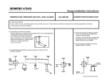
1. Start by removing the four (4) cap nuts and washers on
the back of the tachometer. (For the Street Eliminator, see
Diagram A; for the Comp Eliminator, Diagram B; for the
Pro Eliminator, Diagram C; and for the Top Eliminator,
Diagram D.)
2. Before removing the mounting cup, spray the five wires
with any of the following products: WD40, ARMOR-ALL,
or any rubber/vinyl protectorant. This will allow the wires
to slide through the rubber grommet.
3. Take off the back cap. Set the selector switches to match
the cylinder and ignition type you are using. Switches 1 & 2
Page 1
6HOHFWRU6ZLWFKHV
&'%R[
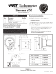
Diagram A
Street Eliminator Dimensions and Switch Settings
Part # 0 511 012 263 Rev. 10/03
0RXQWLQJ&XS
&DS1XW
.H\SDG
6KLIW/LJKW
6KLIW3RLQWHU
7\SH%XOE
6HOHFWRU6ZLWFKHV
Diagram B
Comp Eliminator Dimensions and Switch Settings
0RXQWLQJ&XS
5(&$//
7$&+
5306(7
&/($5
.H\SDG
6KLIW/LJKW
'LJLWDO'LVSOD\
7\SH%XOE
6HOHFWRU6ZLWFKHV
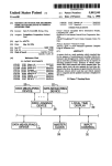
Diagram C
Pro Eliminator Dimensions and Switch Settings
Page 2
&DS1XW
0RXQWLQJ&XS
5(&$//
7$&+
5306(7
&/($5
&DS1XW
.H\SDG
6KLIW/LJKW
'LJLWDO'LVSOD\
7\SH%XOE
6HOHFWRU6ZLWFKHV
Diagram D
Top Eliminator Dimensions and Switch Settings
4. After you have correctly positioned the selector switches
to exactly match your cylinder and ignition type, reassemble
the mounting cup to the rear of the tachometer with the
four (4) cap nuts.
II. Mounting the Tachometer
1. Select a location to mount the tachometer. Eliminator
Tachometers can be mounted in four different ways, depending on your preference. They can be: ¶ Column or roll bar
mounted. A short contoured foot is included so you can
mount the tachometer this way. · In-dash shock mounted.
¸ In-dash flush mounted with an optional U-bracket (#240
104). ¹ Top-dash mounted with an optional long foot (#240
103) for stability.
2. Mount the tachometer, making sure it does not rest against
glass, the windshield post, or the roll bar. (NOTE: To ensure proper operation, don't mount the tachometer too close
to any electrical items like an ignition system box, coils, or
an electrical fuel pump. The wires from these shouldn't be
routed by the tachometer, either.) Recommended installation is on the steering column using a band clamp available
at any local auto parts store. In some instances the drilling
of new holes for the repositioning of the keypad may be necessary. For mounting on the dash, use the optional long
mounting bracket #240 103. Use the holes provided in the
bracket to secure the tachometer. Flush dash mounting requires a 4¾" hole and the optional U-bracket #240 104.
For competition dash mounting, the rubber mounting grommet supplied can be used. This requires a 3½" hole. Remove the rubber grommet from the mounting ring and place
the tachometer into the hole. The mounting cup can be
used for a mounting bracket. Mounting without the grommet requires a 3 3/16 " hole. If the dash panel is ½" thick or
less, the mounting cup can be used for a bracket. Or, use a
modified in-dash bracket #240 104.
3. The keypad can be remote mounted using the optional 6'
remote cable #240 207. Remove the keypad from the mounting ring, then remove the mounting cup. Unplug the cable
from the back of the tach housing. Insert the male end of
the extension cable into the back of the tach. Then insert
the male end of the control pad cable into the female end of
the extension cable. Reattach the mounting cup, then mount
the keypad in the location of your choice.
III. Wiring the Tachometer
1. Remove the key from the ignition and disconnect the
negative terminal from the battery post.
2. Wire the tachometer to the vehicle as shown in Diagram
H on Page 4. Please understand that proper wiring must be
maintained throughout your vehicle. If it isnt, the tachometer may pick up signals that have been produced by electrical devices other than the ignition system. Dont coil up
excess tachometer wires during installation. Cut wires and
cables to length, and route them making sure they cant be
Page 3
CONNECTING TO AN MSD-7AL IGNITION
terminal labeled IGNITION. Make sure all of your connections are tight and clean.
1. Connect the tach using the 10' shielded cable included
with the tachometer. Peel approximately 3 to 4 inches of the
outside covering and aluminum shielding from the gray cable.
This will reveal four individual wires. Three will be insulated and one will be uninsulated.
9. Route the shielded cable through the car as desired. Make
sure no wires can be pinched by pedals, levers, etc. Then
cut the cable to length, leaving a little extra for error.
2. Strip ½" of the insulation from the black, red and white
covered wires.
3. Combine the black and uninsulated wires, which will be
used for the ground, into a 5 16 " ring terminal.
4. On the end of the white insulated wire, which will be
used for the tach signal, install a ¼" female spade terminal.
5. Complete the ignition end of the cable by installing a ¼"
flange spade terminal on the red wire that will be used for
power.
6. Now connect the cable to the MSD-7AL box as shown
below in Diagram I. Connect the O ring with the black
and uninsulated wire to the terminal labeled GROUND.
7. Slide the female terminal with the white insulated wire
onto the terminal labelled TACH.
8. Place the U connector with the red wire on the
10. Peel back approximately 1½" of the gray cover, and the
shield, from the tachometer end of the shielded cable. Cut
the uninsulated wire down to the base of the shielding. Do
notUNDER ANY CIRCUMSTANCESconnect the
shield to the tachometer.
11. Strip about ½" of insulation from the ends of the wires.
Strip the same amount of insulation from the tachometer
wires. We strongly recommend using the provided PosiLockconnectors for splicing the tachometer wires to the
shielded cable. Install them now. Refer to Diagram E.
12. Connect the black wire from the tachometer to the black
wire of the shielded cable (GROUND).
13. Connect the green wire from the tachometer to the white
wire in the shielded cable (TACH SIGNAL).
14. Finally, connect the red wire from the tachometer to the
red wire in the shielded cable. The remaining white
tachomter wire is for illumination, and is connected as
+ TACH
TACH
Posi-Lock Connector
SIGNAL
Diagram I
Wiring to MSD-7AL Ignition
Page 5
YOU MUST USE TWO SETS OF SHIELDED WIRE FOR THIS INSTALLATION!
SHIELDED CABLE #1
Posi-Lock
Connector
TACH SIGNAL
SHIELDED CABLE #2
Posi-Lock
Connector
+ TACH
– POWER
Diagram J
Wiring from the Tachometer to the Ignition Coil or MSD-6
described on Page 4, in the text and in Diagram G.
I. Street Eliminator Operation
CONNECTING TO THE IGNITION COIL OR MSD-6
This tachometer is designed for those individuals whose needs
include only engine RPM monitoring with a manual shift
pointer. This orange pointer, in the center of the tachometer, can be used as a shift point indicator, a reminder not to
exceed a certain RPM, or as a stall point indicator.
1. When connecting to the negative post of the ignition coil
or to the MSD-6 box, run the shielded cableincluded with
the tachometerfor the TACH SIGNAL, the POWER and
the GROUND wires.
2. Ground the shielded wire at the coil. Leave the shield
unconnected at the tachometer. Do not, UNDER ANY CIRCUMSTANCES, connect the shielding to the tachometer.
3. Connect the red tachometer POWER wire to the ignition power, as seen above in Diagram J. Under normal circumstances, this connection should work properly. However, the power may need to be run through a separate
shielded cable directly from the battery, in order to escape as
much noise as possible. If this is the case, a 3-Amp, in-line
fuse and separate power switch should be used. Again, refer
to Diagram J, above.
Tachometer Operation
The Eliminator series consists of four different tachometers
the Street Eliminator, the Comp Eliminator, the Pro Eliminator, and the Top Eliminator. Each is designed to give the
ultimate flexibility in operation and function. Operation of
these state-of-the-art tachometers is profiled in this section.
1. To operate, move the shift pointer by simply turning the
easy-to-hold knob in the center of the tachometer face to
the RPM you wish to highlight.
II. Comp Eliminator Operation
This tachometer features the same manual shift pointer as
the Street Eliminator, as well as a super bright red LED shift
light. The Comp Eliminator shift pointer works the same
way as the Street Eliminator shift pointer. See the above
section for details. To set the LED shift light:
1. Press the RPM set button on the key pad.
2. Press the up arrow until the red pointer indicates the RPM at which you would like the shift
light to illuminate.
3. To lower the RPM, press the down arrow.
4. Once you have chosen your desired RPM, push the RPM
set button in the center of the keypad again. The microprossor
Page 6
will now store the RPM you have selected, and return the
tachometer to the functional mode.
III. Pro Eliminator Operation
The Pro Eliminator not only gives you the advantages of an
LED shift light, but also allows you to set your RPM in precise increments of 10 RPM. And, the Pro Eliminator will
record and store the highest RPM your engine reaches during
the tachometers memory cyclethat is, since the last time
you cleared the memory. Set your shift point as follows:
1. Press the RPM SET button on the keypad. This will lift
the pointer from the LED display window.
2. Press the up arrow until the LED indicates the desired
RPM shift point.
press the down arrow.
3. Should you
need to lower the
shift point, simply
5(&$//
Look at the tachometer
and you will notice three
distinctive features:
1. A 4-digit LED display
at the six oclock position.
This shows the RPM shift
point (e.g. 6.00 = 6000
RPM). The display will also
indicate when you are recording and will show actual elapsed time in the playback mode.
2. An ultra-bright LED shift light at the 3 oclock position.
This will turn on and stay on as long as your engine exceeds
the pre-set RPM shift point.
3. A keypad mounted on the right side of the tach. This
keypad is used to shuttle the tachometer between its four
modes, to set the RPM value of the shift light, to record tachometer activity, and to activate the playback. To operate
the keypad and set the tachometer:
7$&+
5306(7
&/($5
4. To return the tachometer to the operation mode, push
the button marked RPM SET again. The microprocessor
will store the shift point you set.
5. To activate the recall function and reveal the highest RPM
level reached during the memory cycle, press the RECALL
button on the keypad. The digital display will show the peak
RPM level achieved since you last pushed the CLEAR button. This display will last two seconds. To keep the peak
RPM level displayed longer than two seconds, press and hold
down the RECALL button. The display will disappear when
you release the RECALL button.
1. Push the TACH/RPM SET button. Pushing this button
toggles the tachometer between the normal TACH mode
and the RPM SET mode. In the RPM SET mode you can set
the RPM at which you want the shift light to illuminate. To
set this shift point, make sure the tachometer is in the RPM
SET mode. You can tell when tach is in this mode by looking
at the digital display. A small dot appears next to the last
digit on the right when the tach is in the RPM SET mode.
IV. Top Eliminator Operation
VDO Instruments Top Eliminator is the ultimate recording
tachometer. In addition to all of the previously mentioned
benefits in our other Eliminator tachometers, the Top Eliminator enables you to record and play back the tachometer
readings for an entire 50-second or 200-second time period.
The tachometer has four modes of operation:
1.
Normal tach mode (TACH); the tachometer is in the
normal TACH mode when first turned on. The LED
display will show 6.00.
2.
Shift light RPM set mode (RPM SET); the RPM SET
mode is used for setting the RPM level for the shift
light.
3.
Recording mode; the tachometer is capable of recording 50 seconds or 200 seconds of the tachometers activity.
4.
Playback mode (RECALL); the tachometer will play
back the recording it made of the tachometer run in
slow motionshowing elapsed time and RPM values.
When the tach is in the RPM SET mode, the functions illustrated on the bottom half of each keypad button become active
(s, t, and RPM SET). Also, the RPM indicator needle
moves out of the way so you can easily read the LED display.
2. Push the up arrow (s) until you reach the RPM speed at
which you wish the LED shift light to illuminate. If you go too
far, push the down arrow (t) until you get the shift point exactly where you want it (in exact increments or decrements of
10 RPM). Changing the shift point from 6.00 to 8.34, for example, changes the shift point value up from 6000 to 8340 RPM.
The shift light will come on at exactly 8430 RPM.
3. Once you have input the desired RPM level, push the
RPM SET button once again. The tachometer shuttles back
to the TACH operating mode, and the digital display now
indicates the new shift point. The dot in the upper right
corner of the display will disappear, and the pointer will return to the actual engine RPMs.
Page 7
4. To record and playback, press the RPM SET button. The
tachometer will return to the normal TACH operating mode.
The functions designated on the top half of each keypad button will now be active.
5. Press the CLEAR button to erace any previous recordings.
When the memory is erased the display will display three dots
(. . .) to indicate that the tach is recording. During this cycle,
the tach will record for either 50 or 200 seconds, whichever
length you selected when you programmed the tachometer.
When the tach has finished recording, the display will again
display the RPM value you set as your shift point.
6. Press the TACHRPM SET button during recording if
you wish to stop that function and return to the normal
TACH operating mode. You can turn off your engine before
recording has been completed without losing any information. The tachometer also will remember your latest recording even if you remove the power or battery leads.
7. Press the RECALL button to play back what you have
recorded. Playback occurs in slow motionone-third actual timeso you can really study the information. The LED
display will show elapsed time while the pointer is showing
the RPM cycle captured during the recording period. As an
example, a ten-second run requires thirty seconds to view;
but the digital display will show ten seconds as it links the
real time of the run to the recording.
8. Press the TACHRPM SET button during playback if
you wish to return to the normal TACH operating mode.
The stored information will be saved until the next time you
press the CLEAR button.
Troubleshooting
WHEN THE POINTER STAYS AT FULL SCALE
If the tach is turned off during replay and the pointer was
over 4000 RPM, the pointer may swing to full scale. Just
turn on power to the tach and the pointer will reset.
THE TACH POINTER JUMPS ERRATICALLY, THE
SHIFT LIGHT FLASHES RANDOMLY, OR THE DISPLAY SHOWING THE SHIFT POINT GOES BLANK
AND THE POINTER GOES TO 4000-6000 RPM REGARDLESS OF ACTUAL SPEED
The cause of any combination of theseworsened under racing conditionsis extreme electrical noise attributed to:
A. LOW BATTERY VOLTAGE. The operating voltage for
the Eliminator Tachometer is 10.5 volts 16.0 volts.
B. INADEQUATE WIRING. All wiring should be kept as
direct as possible without having excess wires coiled behind
the dash. Avoid bundling power wires with signal wires and
having loose-ended power wires. These will act as transmitting antennas for noise generated by the ignition system, fuel
pump, etc. The MSD crank trigger or mag pickup ignition
trigger should not be routed near spark plug wires or high
current wires.
C. IGNITION WIRES. Solid core metallic wires, old wires
with cracked insulation, or wires with improperly crimped ends
or breaks in the conductors emit large amounts of electromagnetic interference (EMI). Ignition wires can be checked
for defects with a standard ohmmeter. Heli-core wires (MSD)
will read 150 ohms per foot. ACCEL spiral core wire will
read 500750 ohms per foot. Standard resistor wires will
read 500010,000 ohms per foot.
Correct these problems first. If tach problems persist
A. WHEN CONNECTING TO MSD-7AL: Connect the
tach using the shielded cable provided. Connect the shield
and ground wire to the ground post on the MSD box or the
main MSD ground. Connect the power wire to the ignition
terminal on the MSD box, and the signal wire to the tach
output terminal on the MSD box. At the tach end, connect
the red wire to power, the green wire to signal, and the black
wire to ground (see Diagram I on Page 5). DO NOT connect
the shield to the tach under any circumstances.
B. WHEN CONNECTING TO THE IGNITION COIL OR
MSD-6: When connecting to the negative post of the ignition coil or to the MSD-6, run a separate shielded wire for
the signal and the power/ground wires. The shielded wire
from the coil should be grounded at the coil and the shielding left unconnected at the tach end. The power may need
to be run through a shielded wire directly from the battery to
escape as much noise as possible. If you wire in this way, insert a
3-Amp in-line fuse and a separate power switch
( See Diagram J on Page 6).
C. If the shielded wire provided doesnt eliminate all noise
interference, a noise filter should be installed on the power/
ground wires, as close as possible to the tach. Noise filters
Radio Shack #270-051 or MSD #8830will eliminate any
remaining noise on the power wire from the ignition system,
fuel pump, alternator (if equipped), relays, etc. The tachs
white illumination wire may also need to be connected with
the red power wire after the noise filter. See Diagram G on
Page 4. These solutions should solve any problem you encounter. But if you still need assistance, call our Technical
Service Coordinator at 1-800-265-1818.
Siemens VDO Automotive Limited Warranty
Siemens VDO Automotive warrants all merchandise against defects in factory
workmanship and materials for a period of 24 months after purchase. This warranty applies to the first retail purchaser and covers only those products exposed
to normal use or service. Provisions of this warranty shall not apply to a VDO
product used for a purpose for which it is not designed, or which has been
altered in any way that would be detrimental to the performance or life of the
product, or misapplication, misuse, negligence or accident. On any part or product found to be defective after examination by Siemens VDO Automotive,
Siemens VDO Automotive will only repair or replacethe merchandise through the
oringinal dealer or on direct basis. Siemens VDO Automotive assumes no responsibility for diagnosis, removal and/or installation labor, loss of vehicla use, loss
of time, inconvenience or any other consequential expenses. The warranties herin
are in lieu of any other expressed or implied warranties, including any implied
warranty of merchantabilty or fitness, and any other obligation on the part of
Siemens VDO Automotive, or selling dealer.
Siemens VDO Instruments . http://sso-usa.siemensvdo.com/ . Phone: 1-800-265-1818
Page 8
Eliminator Tachometer Filter Installation Instructions
Addendum for Eliminator Tachometer Installation Instructions
Siemens VDO
®
Allentown, Pennsylvania USA
THE INSTRUCTIONS FOR OPERATION AND ELECTRICAL WIRING FOR THIS TACHOMETER FOLLOWS. USE IS RESTRICTED TO 12 VOLT NEGATIVE GROUND ELECTRICAL SYSTEMS.
IMPORTANT: The correct installation and wiring
of this filter is essential for proper operation of all
Eliminator Tachometers.
The filter included with your Eliminator Tachometer must be
used in order for the instrument to function properly. The
best place to mount the filter is on the back of the tachometer itself, using the nuts that secure the back cover [the metal
cup that goes over the DIP switches and light socket]. The
best time to mount the filter is when you replace the back
cover after initially setting the dip switches.
I. Wiring the Filter to the Tachometer
1. Make sure that the wires from both the filter and the tachometer are cut to an appropriate length, and that about ½"
of insulation is stripped from the ends of each of these wires.
It is best to use insulated butt connectors to splice together
the wires from the filter and the tachometer.
2. Push the stripped end of the RED and WHITE tachometer wires into one side of the butt connector. Use pliers or
other crimping tool to crimp the wires in the butt connector.
Gently tug the wires after you have crimped them to make
sure they are secure.
3. Place the RED wire from either side of the filter into the
other side of this butt connector, and crimp it into place.
Again, check it to make sure it is secure. Refer to Diagram A
to see a properly crimped butt splice. See Diagram B for color
codes and general tachometer wiring descriptions.
4. Repeat the connecting (crimping) process for the BLACK,
and GREEN wires from the tachometer and the filter. Make
sure all of the filter wires you connect to the tachometer are
from the same side of the filter. When you are finished, the
BLACK and GREEN wires from the tachometer should be
securely connected to the BLACK and GREEN wires from
one side of the filter. Crimp the YELLOW wire from the
tachometer into one side of a butt connector. Crimp the
WHITE wire from the filter into the other side of this butt
connector. When you are finished, the connections should
resemble those in Diagram A, below.
Refer the the main installation manual for instructions on
how to wire your Eliminator Tachometer Filter to the engine
of your vehicle. The second set of wires from the filter are to
be attached to the battery, ground and ignition using the
shielded cable which also came with the tachometer.
Diagram A
Proper connection of the filter to the ELIMINATOR Tachometer using the supplied Butt Splices
Part # 0 511 012 332 Rev. 7/03
Diagram B
Eliminator RF/EMI Filter Color Code and Hookup Description
Note:
When following the wiring instructions in the
main installation manual, consider the wires from the filter as if they were the actual wires from the tachometer
itself.
II. Mounting the Filter on the Tachometer
1. Choose any two nuts that are diagonally across from each
other on back of the tachometer for mounting the filter. See
Diagram C, below.
2. Remove these nuts and the accompanying lock washers
and set them aside.
3. Slip the mounting holes in the filter over the studs from
which the nuts were removed. The filter will fit securely over
these studs. Push the filter down until it is flush with the
surfaces of the tachometer and the grommet that surrounds
the wires coming from the tachometer.
4. Replace the lock washers and nuts, and tighten the nuts
securely. Mounting of the filter is now complete.
Diagram C
Proper mounting of the Eliminator RF/EMF Filter on the back of the Tachometer
Tachometer Installation and Operation Instructions
Addendum for Comp Eliminator II Tachometer
Siemens VDO
®
Allentown, Pennsylvania USA
THE INSTRUCTIONS FOR OPERATION AND ELECTRICAL WIRING FOR THIS TACHOMETER FOLLOWS. USE IS RESTRICTED TO 12 VOLT NEGATIVE GROUND ELECTRICAL SYSTEMS.
IMPORTANT: The installation and general
wiring for this tachometer is essentially the
same as for those mentioned elsewhere in
these instructions. There are minor
differences, however, which are described here.
Please read and understand them before
proceeding.
I. Comp Eliminator II Switch Settings and Wiring
Wiring for the Comp Eliminator II is the same as for the other
tachometers. Please refer to the proper sections of the main
Eliminator Tachometer Installation and Operation Instructions to
determine the proper switch settings and wiring for the vehicle and tachometer you are using. Also, refer to the diagrams
contained in this addendum and note the subtle changes between the Comp Eliminator II and the other Eliminator Tachometers.
II. Comp Eliminator II Operation
The unique feature of this tachometer is a high/low RPM
tell-tale memory. Take advantage of this feature by performing the following steps:
START:
1. Be sure to bring the car to speed before pressing the
START/STOP button on the keypad. NOTE: This is criti-
cal! If the START/STOP button is pressed before the car has
reached running speed, or if the process is not stopped (by pushing STOP) before slowing the
car, an incorrect low RPM
value will be stored in the
tach! Pressing the
START/STOP button
will cause the tach to begin storing high and low
RPM values. This is indicated by a one-second blink
of the shift light LED, followed
by a flicker every second to show that the tach is still searching for high and low levels.
STOP:
2. The tachometer is programmed to search for high and low
RPM levels. To stop this function at any time simply press
ANY button on the keypad. Function stop is indicated by
two blinks of the shift light LED.
RECALL:
3. To recall high and low RPM values, press the
HI/LOW button on the keypad. The tach pointer
will move to the high RPM reading. A second
press of the HI/LOW button will move the pointer
to the low RPM value. Pressing the HI/LOW button again will repeat the process.
HI
LOW
TACH
SET
START
STOP
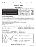
*5((1
,JQLWLRQ 7DFKRPHWHU VLJQDO FRQQHFWLRQ
:+,7(
2SWLRQDO H[WHULRU VKLIW OLJKW
%/$&.
7DFK JURXQG FRQQHFW WR FRPPRQ FKDVVLV JURXQG
5('
YROW SRZHU FRQQHFW WR IXVH SDQHO
6+,(/'
Diagram A
Comp Eliminator II Wire Color Code and Hookup Description
Part # 0 511 012 411 Rev. 07/03
To return to tach mode, press either the START/STOP button, or the TACH/SET button one time.
SHIFT LIGHT SETTING:
4. To set the shift light to come on at your desired shift point,
press the TACH/SET button. The pointer will move to the
current set point and the shift light LED will blink one sec-
ond on, then one second off to indicate the ready to set
mode. Set the shift point by pressing either the START/
STOP button or HI/LOW button to move the pointer to the
desired shift point. When you reach the RPM where you
want the shift light to come on, press the TACH/SET button
again. Your shift point is stored in memory and the tach returns to the tach mode.
0RXQWLQJ &XS
HI
LOW
TACH
SET
START
STOP
&DS 1XW
.H\SDG
6KLIW /LJKW
6KLIW 3RLQWHU
7\SH %XOE
6HOHFWRU 6ZLWFK
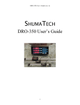
6(/(&725 6:,7&+ 6(77,1*6
&</,1'(5 6(/(&7,21
&</,1'(56
,*1,7,21 7<3(
6:,7&+ 6(77,1*6
,*1,7,21
6:,7&+ 6(77,1*
RQ
6WDQGDUG
RQ
RII RQ
(OHFWURQLF
RII
RQ RII
&' %R[
RQ
&' 6LGH RI &RLO
RII
127( 6ZLWFK LV QRQIXQFWLRQDO RQ WKLV WDFKRPHWHU
Diagram B
Comp Eliminator II Dimensions and Switch Settings