1
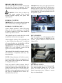
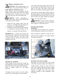
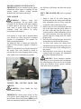
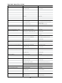
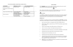
OPERATORS
MANUAL
ENGLISH
TRACTOR MODEL:
MTS2611K
CUTTING DECK MODEL:
MTS4411, MTS5411
Copyright 2011 HTC All Rights Reserved.
Augusta, KS. Printed in USA
1
SAFETY FIRST
IMPORTANT: DO NOT attempt to start the
engine or operate this machine until you have
read all safety information and operating
procedures in this manual.
Disengage clutch and lock steering levers in
neutral before attempting to start the engine.
Disengage clutch, stop engine and set parking
brake before leaving the operator’s position.
This is a Safety Alert Symbol used to alert
you to possible danger to you or someone else’s
personal safety. Be alert to the accompanying
messages in this manual.
Disengage clutch when transporting or not in
use.
Disengage clutch and stop engine before making
any repairs of adjustments.
CAUTION:
Your ZIPPER MOWER is equipped with an
Ignition Interlock Safety System. This system is
designed to protect the operator and others in the
immediate area by preventing the engine from
starting when the PTO switch is on or the
Steering Levers are not in the locked position.
Take all possible precautions when leaving the
mower unattended, such as disengaging the
PTO, lowering the deck, locking the steering
levers in neutral, setting the parking brake,
stopping the engine and removing the key.
IMPORTANT: Listed below are a common set
of rules you should read and follow.
REMEMBER, your safety and the safety of
others depends on the operator’s awareness and
adherence to these basic rules. Know the
controls and how to stop safely.
Reduce speed and exercise extreme caution on
slopes and in sharp turns to prevent tipping or
loss of control. Be especially cautious when
changing direction on slopes.
READ THE OPERATORS MANUAL
Watch out for traffic when crossing or near
roadways.
Always stay alert for holes, rocks, and roots in
the terrain and other hidden hazards.
DO NOT allow children to operate the mower.
When using any attachments, Always operate
the cutting deck with deflector chute in place
and in the lowered position. NEVER direct
discharge of material toward bystanders or allow
anyone near the mower while in operation.
DO NOT allow adults to operate without proper
instruction.
DO NOT carry passengers. Keep children and
pets a safe distance away.
Handle gasoline with care (it is highly
flammable)
Use approved gasoline container.
Never remove the fuel cap or add gasoline to a
running or hot engine.
DO NOT stop or start suddenly when going up
or downhill. Mow up and down the face of steep
slopes; never across the face of the slope.
Clear the work area of objects which might be
picked up and thrown.
DO NOT fill tank indoors and wipe up any
spilled gasoline
Keep the tractor and attachments in good
operating condition and keep safety devices
working properly.
DO NOT run the engine indoors exhaust fumes
are dangerous.
Keep all nuts, bolts and screws tight to be sure
the equipment is in safe working condition.
2
SAFETY FIRST (CONT.)
Never store the equipment with gasoline in the
tank inside a building where fumes may reach
an open flame or spark.
control panel on the tractor and under the left
hand deck cover on the deck.
Upon delivery of the machine, the dealer is to
review all the controls and how to operate the
unit as covered in this manual with the owner.
Allow engine to cool before storing in any
enclosure.
Emphasize all the safety precautions covered in
the manual.
To reduce fire hazard, keep the engine free of
grass, leaves, or excessive oil and grease.
Both dealer and customer must sign the
warranty registration card upon delivery.
The tractor and attachments should be stopped
and inspected for damage after striking a foreign
object, and the damage should be repaired
before restarting and operating the equipment.
NOTE: All references to “Right, Left, Front,
and Back” are from sitting in the drivers’ seat.
DO NOT change the engine governor settings
or over speed the engine.
WHEELS
Remove packing crate from the machine and
install the drive wheels and tail wheel. Fill the
tail wheel with grease
When using the mower, proceed as follows:
Mow only in daylight or in good artificial light.
Never make a cutting height adjustment while
engine is running.
Shut off engine when removing the grass
catcher or unclogging the chute.
Check the blade bolt tightness at frequent
intervals.
BATTERY
Connect positive cable first, then connect the
ground cable.
IGNITION INTERLOCK SAFETY
SYSTEM
DANGER: Failure of the IGNITION
INTERLOCK SAFETY SYSTEM, together
with operation of the machine could result in
personal injury.
Disengage power to mowing deck before
backing up.
DO NOT mow in reverse unless absolutely
necessary and then only after careful
observation of the entire area behind the mower.
Check the Interlock Safety System to make sure
it is functioning properly. The engine must not
start unless the steering levers are in the neutral
locked position and the PTO switch is off. The
engine must kill if the operator leaves the seat
with the steering levers down and/or PTO
switch in the on position.
PREDELIVERY INSPECTION
NOTE TO CUSTOMER: The ZIPPER
DEALER is expected to complete the following
pre-delivery operations and review all safety
precautions in this manual WITH YOU before
or upon delivery of this machine.
BEFORE OPERATION
The following list should be performed before
starting the engine on a new machine.
REGISTRATION AND DELIVERY
Fill out the warranty registration card and mail
the proper copy to ZIPPER MOWERS within
Ten business days.
1. Check the engine oil level (see engine
manual for oil recommendations)
2. Check the oil level in the hydrostatic oil
tank located at the back of the engine cavity
under the left hand control panel. The oil
level should be 1” below the top of the tank.
Warranty is registered under Model and Serial
Number located under the front of the left hand
3
BEFORE OPERATION (CONT.)
3. (See
Hydraulic
System
for
oil
recommendations)
4. Fill fuel tank with fresh clean gasoline (see
engine manual for recommended fuels)
5. Check tension on the hydraulic pump drive,
deck drive, and blade drive belts. (see belt
adjustment section for proper belt
adjustments)
6. Check pressure in all tires (Figure 1) The
drive wheels and gauge wheels must have
equal pressure to maintain an even cut.
TIRE PRESSURE
Drive Tires
PSI
12 to 16
Tail Wheel
10 to 18
Gauge Wheel
WARNING: Do not operate
without grass chute spring installed.
8 to 12
Figure 01
deck
Check the blade bolts to be sure they are tight.
Also remove deck cover and check the deck belt
tension.
INSTALLING THE CUTTING DECK
The following steps are recommended for
installing the deck:
Check deck for level and correct pitch.
Remove the deck from the shipping box and
place on level surface in front of tractor.
WARNING: Never operate the deck
without grass chute and belt guard in place.
Install gauge wheel brackets using 5/16-18
carriage bolts, lock washers and hex nuts. Install
gauge wheel adj. tube and deck adj. bolt and
nut. Install grass chute by starting the hinge pin
from the back of the deck through the first hinge
on the grass chute and deck. Place the grass
chute spring over the hinge pin and slide the
hinge pin through the front hinge on the deck
and grass chute. Place the handle of the pin in
the retainer on the grass chute and lock into
place with the cotter hairpin.
1. Remove (2) 1/2 bolts from lift arm ball
joint and (2) 1/2 adj. pins from back of
deck.
2. Remove belt guard from deck gearbox.
3. Raise deck lift to the middle position, align
deck under arms and lower lift to down
position. Install bolts through deck and ball
joints.
4. Place drive belt over gearbox pulley and
replace belt guard.
5. Raise deck lift enough to install adj. pins at
desired cutting height.
6. Raise deck to full up position and install
front gauge wheels and set mounts at
desired cutting height.
7. Lower deck and adj. the deck drive belt.
WARNING: Only operate the deck while
sitting in the operator’s seat. Make sure the area
is clear of all hazards, persons, and pets when
running the deck
4
OPERATION
NOTE: The design and configuration of
equipment, hazard control and accident
prevention are dependent upon the proper
training of personal involved in the operation,
transportation, maintenance and storage of the
equipment. DO NOT let children or unqualified
operators run the equipment.
STOPPING THE ENGINE
Run engine at half speed for a minimum of
one minute with no load for cool down
purposes.
Turn ignition key to OFF and remove key.
BRAKING
Forward or reverse movement is slowed or
stopped by returning the steering levers
toward the neutral position.
STARTING THE ENGINE
NOTE: The PTO switch must be in the off
position and the steering levers in the neutral
lock position before the engine starter will
engage. In this manual it will be referred to as
the IGNITION INTERLOCK SAFETY
SYSTEM. (IISS)
NOTE: The parking brake is for parking only.
DO NOT use the parking brake to slow or
stop the machine or you risk damage to the
hydraulic drive system.
WARNING: never operate this machine
with the IISS disconnected, bypassed or
malfunctioning.
STARTING THE ENGINE (CONT.)
STEERING
The steering levers control forward and
reverse movement, speed of travel as well as
turning and braking. Each lever controls the
direction and speed of the corresponding drive
wheel. To go forward, push both levers
forward at the same time. To go backward,
pull both levers toward the operator at the
same time. To turn the machine to the right,
move the right lever back and/or the left lever
forward. To turn left, move the left lever back
and/or the right lever forward.
WARNING: Engine exhaust gases
contain poisonous carbon monoxide. Avoid
breathing fumes and never run the engine in a
closed building or confined area.
IMPORTANT: Always apply the parking
brake before starting the engine.
Pull choke out to the CLOSED position. On a
warm engine leave choke in the OPEN
position.
Open throttle to half speed.
Turn ignition key to START. Return key to
ON position as soon as engine starts.
NOTE: The ignition switch has an integrated
light switch so it has 2 ON positions; one is to
turn on headlights.
Slowly push the choke down to the OPEN
position after the engine starts to warm up.
NOTE: When turning always make sure both
drive wheels are rotating this helps prevent
turf damage.
CAUTION: Any sudden movement of
the steering levers will result in sudden
braking or opposite direction of travel.
LIFTING THE ATTACHMENTS
WARNING: Never travel at road speeds
with the attachment in the raised position.
Allow the engine to warm up at a low RPM for
2 to 5 min. before putting the engine under full
load.
The mower is equipped with an electric
lift to raise and lower the attachments. To rise
the attachments push down on the forward half
of the lift switch. (Located on the L/H control
panel forward of the steering lever) To lower,
push down on the aft side of the lift switch.
IMPORTANT DO NOT crank the engine
continuously more than 10 seconds at a time. If
the engine does not start, allow a 1 min. cool
down period between start attempts. Failure to
follow these guidelines can burn out the starter.
5
LIFTING THE ATTACHMENTS (CONT.)
The mower deck should always be operated
with the lift in the full down position. Hold the
lift switch down until you hear the lift make a
ratcheting sound. This allows the deck to float
over uneven terrain.
IGNITION SAFETY SYSTEM
Check the IISS daily, prior to operation. This
system is important to the safety of persons in
the area as well as operator safety. It should be
repaired immediately if malfunctioning. To
check the system, follow these steps.
On side hills, you can add extra traction to the
drive wheels by raising the lift up just until the
back of the deck begins to rise
Begin with the parking brake engages, PTO
switch off and steering levers in neutral lock
position.
ENGAGING THE DECK
OR ATTACHMENTS
The deck is driven by an electric clutch
attached to the engine crankshaft. To engage
the deck, set the engine throttle to 1/3 speed
and lift up on the PTO switch located on the
R/H control panel aft of the steering lever. (
red switch)
Move the steering levers into the operating
position and turn the ignition key to start. The
starter should not respond.
Return the levers to the neutral lock position
and pull the PTO switch to on and turn ignition
key. The starter should not respond.
WARNING: Operator must be in the
seat for the PTO to activate. If the attachment
runs without the operator in the seat, stop
engine and repair IISS before further use.
If the starter responds to either of these tests,
turn off ignition switch and make necessary
corrections before further operation of the
machine. Otherwise proceed with preoperative
checks.
When side discharge deck of other
attachments are used, extreme caution must be
taken not to direct discharge in the direction of
persons or pets For best operation of the deck,
the engine should be run at full throttle and the
ground speed controlled by the steering levers.
SEAT SWITCH
The seat switch should be checked before each
operation. The machine should not be operated
with an inoperative switch. To check the seat
switch, follow these steps.
SERVICE AND ROUTINE
MAINTENANCE
Start engine while seated in the operators’ seat.
Move steering lever to operating position and
rise from the seat- the engine should kill.
WARNING: When servicing the
machine, shut down machine, remove key, lock
steering levers in neutral lockout and set
parking brake.
Move the steering lever back to neutral lock and
restart the engine. Pull the PTO switch to on
position and rise from the seat – the deck should
disengage and the engine should kill.
The table Figure 00 is for your quick reference.
The maximum intervals between services are
listed. If dry and/or dusty conditions are
encountered, time between service should be
decreased.
If the engine fails to kill during either of these
tests, turn off ignition switch and correct
immediately.
BREAK IN SERVICES
A new engine requires special break-in
maintenance. Read the appropriate section of
the engine manual. Engine oil and filter should
be changed after first 5 hours of operation.
NOTE: Routine lubrication and maintenance
are the most important steps toward longer
machine life, reducing down-time, upkeep
costs, increasing productivity and quality
mowing
6
BREAK IN SERVICES (CONT.)
All new belts should be checked and adjusted
after the first 5 hours of operation. See belt
adjustment section on proper belt adjustment.
IMPORTANT: Always keep the transmission
pump fins, cooling fins clean. If a fan becomes
damaged replace it with a new one before next
use. Extra heat caused by oil and dirt build up
on the pump fins will cause premature wear on
the hydraulic system.
WARNING: Never check or adjust any
belts with engine running. Never operate
machine without replacing belt guards after
adjusting belts.
HYDRUALIC SYSTEM
IMPORTANT: Care must be taken to keep any
dirt or moisture from entering the hydraulic
HYDRAULIC SYSTEM (CONT.)
system. Minute amounts of either will greatly
reduce the life of the components. Care should
be taken to remove all dirt from around the
breather cap before removal.
DECK GEARBOX
The deck gearbox is a sealed unit and is filled
with 6 oz of 90-weight oil. NOTE: Do not
overfill; gearbox should be about half full
(Figure 09A).
The hydraulic tank is located under the seat lid
mounted on the forward cross support.
Check hydraulic oil daily. Oil level should be at
or above fill the line when cold. To check the
oil, remove breather cap, oil should be visible in
the contaminant screen inside the tank.
IMPORTANT: Use only 15W-50 full synthetic
engine oil in the hydraulic system and an
approved 25-micron rated oil filter.
The hydraulic filter should be changed after the
first 100 hours of operation, then every 500
hours thereafter.
NOTE: If the performance of the drive system
becomes sluggish or there is an appearance of
dirt or water in the oil, the oil and filter should
be changed in the system.
ELETRICAL SYSTEM
The electrical system is a 12-volt neg. ground.
The factory-installed battery is a U1L9. The
battery is located under the seat lid. Check
battery connections every 40 hours to ensure
they are clean and tight.
Great care must be taken to insure that all
particles that may cause contamination to the
system be removed from around the filter and
housing before removal. To clean around the
filter use a solvent and brush to remove oil and
dirt. Then use compressed air to remove any
final debris from the area.
7
ELECTRICAL SYSTEM (CONT.)
lock position and apply parking brake. Place an
oil pan under the drain plug, located at the
front of the base, and remove drain plug.
Remove the old filter. Lubricate gasket on new
WARNING: When jumpstarting a low
or dead battery, keep away from open flame or
ELECTRICAL SYSTEM (CONT.)
spark. Always wear eye protection. Do not
breathe battery fumes and avoid skin contact
with battery acid. If contact does occur, flush
area with cold water and consult physician.
filter with new oil and install. Tighten filter by
hand only. Replace oil drain plug and add new
oil (oil fill hole located on aft valve cover). DO
NOT overfill. See engine manual for capacity,
API service class and viscosity.
WARNING: When jumpstarting a
battery follow these steps to avoid sparks that
could cause gases to explode.
WARNING: During normal operation,
oil heats to a level that may cause severe burns.
Allow engine to cool before service.
1. Attach the first jumper cable from the
positive (+) terminal of the good battery to
the positive (+) of the dead battery.
2. Attach the second cable from the negative
(-) terminal of the good battery to the
negative (-) terminal of the dead battery.
ENGINE AIR FILTER
MTS2611K
Clean/change outer element every 150 hours.
Clean/change inner element every 250 hours.
IMPORTANT: A 30-amp fuse protects the
electrical system. If there is an overload on the
circuit, the fuse will blow. The cause of the
overload should be located and fixed before
installing a new fuse.
These procedures should be performed more
often in dusty conditions. See engine manual
for further instructions.
ENGINE OIL SYSTEM
Check engine oil level at the start of each day
and again after 4 hours of operation. Oil must
always be between the marks on the dipstick.
Refer to engine manual for oil change
intervals.
ENGINE COOLING SYSTEM
The engine is an air-cooled unit. Grass, chaff
or dirt may clog the rotating screen and the aircooling system. Yearly or every 100 hours
remove the cooling shrouds and clean cooling
fins. Also, clean dirt and oil from the external
surfaces of engine, this may also cause
improper cooling. In dusty conditions clean
more often.
To change oil, park track on a level surface,
remove key, put steering lever in the neutral
8
ENGINE COOLING SYSTEM (CONT.)
IMPORTANT: Never attempt to make engine
adjustments while engine is running. Do not
operate engine without cooling shrouds
installed, this will cause overheating.
the flip link to fall below the slide tube on the
tractor.
SHUT THE ENGINE OFF and set parking
brake.
FUEL SYSTEM
1. Stand in front of the deck facing the
machine and raise the cutting deck until the
deck adjustment pins are loose using the
cutting deck lift switch (Figure 05A).
2. Remove the two deck adjustment pins and
lift up the deck using the gauge wheels or
the nose roller and raise the deck into a
vertical position. While holding the deck in
the vertical position, lower the deck to the
ground using the cutting deck lift switch
(Figure 07A).
3. Place the deck adjustment pins in the deck
lockup holes located in the lift brackets.
4. To lower deck remove the cutting deck
adjustment pins from the lock up holes and
5. lower the front edge of the cutting deck to
the ground.
6. Raise the back of the deck to the desired
cutting height and replace the adjustment
pins in the adjustment brackets.
WARNING: Observe usual fuel
handling precautions. Do not smoke while
refueling. Do not fill tank with engine running
or while engine is hot. Keep fuel away from
open flame or spark. Keep fuel in proper
container. Read and observe all safety
precautions in this manual.
Fuel capacity is 10 gal. tank is located behind
seat. Always use clean fresh fuel. Unleaded
gasoline is recommended. See manual for
further recommendations.
An inline fuel filter is located just before the
engine. If filter becomes clogged, it should be
replaced.
There is a fuel shutoff valve located forward of
the engine. This valve should be closed to
prevent fuel loss when changing filters, doing
other engine work or transporting machine.
WARNING: Never transport machine
with deck in service position; this can damage
the lift mechanism. Never service deck without
safety pin installed. Never operate machine
with deck in service position.
TILTING THE CUTTING DECK FOR
SERVICE
WARNING: Never handle the deck
while engine running.
IMPORTANT: Always place mower on flat
level surface before tilting deck. Always use
the Effortless Deck Lift System (EDLS) to tilt
deck never manually tilt deck; this will allow
9
TILTING THE CUTTING DECK FOR
SERVICE (CONT.)
LUBRICATON
NOTE: The best time to grease the bearings
on your ZIPPER is right after you have
completed mowing and cleaned the machine.
NOTE: Use SAE multi-purpose grease on all
grease zerks.
There are nine grease zerks on the machine.
The deck gauge wheel and tail wheel bearings
should be greased every 8 hours. The spindle
bearings and gauge fork and tail fork bearings
should be greased every 40 hours
DECK HEIGTH ADJUSTMENT
WARNING: shut off engine and remove
key before adjusting cut position.
Cutting height can be adjusted from 1” to 5” on
all decks.
To adjust, raise deck, remove front adj. nuts
and bolts and place them in desired cutting
height and replace bolts. Relieve pressure on
rear pins using deck lift and remove pins and
adjust back of deck. For best cutting results, in
most conditions, the back of the cutting deck
should be 1/4” to 1/2" higher than the front.
BLADE CARE
DANGER: Never inspect or remove
blades with engine running or key in ignition.
Always remove key and set parking brake.
NOTE: For best cut quality keep the mower
blades sharpened and balanced.
To service blades, tilt and lock deck using the
EDLS (see tilting deck for service section). Do
not sharpen blades while mounted on the
spindles. Blades may be sharpened on a
grinder or by filing. When grinding, care
should be used to maintain blade balance. A
blade balancer should be used after sharpening.
Unbalanced or bent blades will cause excessive
vibration and decrease the life of the deck
WARNING: Never use any form of heat
to straighten a bent blade. Never weld a
cracked or broken blade- REPLACE THEM.
BELTS
10
BLADE CARE (CONT.)
BLADE DRIVE BELT
TO ADJUST:
WARNING: Never check, adjust or
change any belt with engine running.
NOTE: Do not over tighten any belt. A belt
that is to tight will run hotter, create
unnecessary side pressure on bearings and
cause premature failure of belts and bearings.
WARNING: Never check, adjust or
change any belt with engine running.
1. Remove L/H and large center deck cover.
2. Loosen nut on belt tightener retainer bolt.
3. Adjust tension bolt to obtain proper tension
on belt. Deflection on longest span should
be 5/8 from centerline with 5 lbs force.
DECK DRIVE BELT
WARNING: Never check, adjust or
change any belt with engine running.
TO ADJUST:
1. Loosen the two arm retaining bolts on both
deck arms.
2. Loosen the lock nut on the deck belt
adjustment bolt. Turn the adjusting bolt
clockwise to tighten the belt. Both arms
must be adjusted the same amount when
adjusting.
3. The deck drive belt should have 1/2" of
deflection from the centerline with 5 lbs. of
force.
4. Retighten lock nuts on adj. bolts and
tighten arm retainer bolts.
WARNING: Do not operate machine
without all belt guards and deck covers in
place.
TO REPLACE:
1. Loosen deck drive belt.
2. Remove all deck covers.
3. Loosen belt tightening retaining bolt and
adjustment bolt.
4. Unbolt gearbox mount from deck and
remove the belt from under gearbox pulley.
5. Loosen the 5” idler pulley and remove the
belt from between the front spindle pulley
and the 5” idler.
6. Replace with a factory replacement belt.
7. Place new belt around the two outer spindle
pulleys and between the 5” idler and center
pulley. Tighten idler at this point.
8. Place belt over the gearbox and reinstall the
gearbox mount.
9. Adjust the blade drive (see above).
Readjust new belts after 5 hours.
10. Replace deck covers
11. Adjust deck drive belt (see deck drive belt
section)
TO REPLACE:
NOTE: Also check the hydraulic pump belt at
this time. It is a good idea to change both belts
at same time.
1. Loosen arm retainer bolts on right arm
only. Turn adjusting bolt counterclockwise
to loosen belt.
2. Remove belt guard from gearbox.
3. Loosen clutch stop and slide fwd. Unplug
wires to electric clutch.
4. Remove belt and install new one.
5. Reverse steps 1-3
6. Adjust belt tension (see Above). New belts
should be rechecked after 5 hrs.
7. Adjust L/H deck arm to same length as
R/H
11
TRANSMISSION DRIVE BELT
TO ADJUST:
EXTERIOR SURFACE
The machine should be washed regularly to
maintain its appearance.
WARNING: Never check, adjust or
change any belt with engine running.
1
2
3
4
WARNING: When washing the inside
of machine, DO NOT direct water spray
Shut off the engine, remove key and set
parking brake.
Loosen jam nut on tension eye-bolt
(located on the upper hydraulic pump)
Tighten nut on aft side of mount bracket to
increase tension on belt. Belt should have
1/2 “ deflection with 5 lbs force.
Tighten jam nut.
around the hydraulic oil tank breather cap. The
mower deck should be cleaned after each day
of use for best mowing results. Water pressure
from a garden hose will clean the underside of
the deck if the grass clippings have not dried.
Otherwise, a putty knife or other flat object
may be needed to remove dried clippings and
dirt.
WARNING: Never check, adjust or
change any belt with engine running.
1. Shut off engine, remove key and set
parking brake.
2. Loosen deck drive belt and remove from
the electric clutch (see deck drive belt
section)
3. Loosen transmission belt tension eye-bolt
and remove old belt.
4. Install new belt and adjust tension
5. Replace deck drive belt (if old belt is worn
it is a good idea to change at this time also)
6. Readjust clutch stop and attach clutch wire.
7. Adjust deck drive belt.
IMPORTANT: Every 40 hrs or each week
clean debris from inside deck covers. Failure to
do this may cause damage to deck idler pulleys
and/or the deck gearbox.
WARNING: Do not operate machine
without all guards and covers in place.
STORAGE:
To insure the machine will be ready for the
next mowing season, the following steps
should be taken when storing the machine at
the end of the season.
1. Wash the machine to remove all grass, dirt
and debris.
2. Visually inspect for any worn or damaged
parts that need replaced and order them
from your ZIPPER dealer.
3. Lubricate the machine according to
lubrication instructions.
4. Lightly oil the underside of deck to prevent
rusting.
5. Drain fuel tank and run engine to remove
all gas from carburetor.
6. Perform other engine operations as outlined
under storing engine in the engine manual.
7. Remove battery and store in a dry place.
Protect the battery from freezing
temperatures. Occasionally charging the
battery during storage will extend battery
life.
8. Store machine in dry place away from
flames
STEERING LINKAGE
TO ADJUST:
The machine has been set at the factory so that
it will not creep forward or backward while the
engine is running and the steering levers are in
the neutral lock position. However, if the
machine should begin to creep or one wheel
runs faster than the other, adjustments must be
made. Contact authorized ZIPPER dealer for
steering linkage adjustment.
ELETRIC CLUTCH
TO ADJUST:
A sign that the electric clutch is out of
adjustment is when the clutch will engage with
the clutch cool but not when the clutch is
warm. Take machine to authorized ZIPPER
dealer for clutch adjustment.
12
MAINTEANCE SCHEDULE
Daily
Ref
Service at Intervals
Indicated
Daily
After
4
Before
Operation
Operation
Hr.
8
25
40
100
500
Hr.
Hr
Hr
Hr
Hr
A
Verify Ignition Safety
System
X
A
Check Engine Oil
X
A
Check Hydraulic Oil
X
A
Visually Inspect Tractor
X
A
Visually Inspect Tires
X
A
Clean Underside of Deck
A
Lube Deck Gauge
Wheels
X
A
Lube Tail Wheel
X
B
Clean Air Filter Element
A
Lube Gauge Wheel Fork
Tubes
X
A
Lube Tail Wheel Fork
Tube
X
A
Check Oil in Gearbox
X
A
Lube Spindle Housing
X
A
Check Battery and
Connections
X
C
Change Engine Oil (2)
X
C
Change Oil Filter (2)
X
B
Change Air Filter
Cartridge (1)
X
A
Check Tire Pressure
A
Torque Wheel Nuts
A
Change Hydraulic Oil &
Filter (3)
X
A
Change Gearbox Oil
X
X
X
X
X
X
NOTES:
1. More often under dusty conditions
2. Initial oil and filter change is at 5 hrs.
3. Initial filter change is at 100 hrs
Figure 00
REFERENCE:
A-See Operators Manual
B-See Engine Manual
C-See Both Operators and Engine Manuals
13
TROUBLE SHOOTING GUIDE
SYMPTOM
Starter Does Not Crank
POSSIBLE CAUSE
CORRECTIVE ACTION
Ignition Interlock Safety System Not Engaged Engage System
Safety Switch Faulty
Replace Switch
PTO Switch in On Position
Put Switch in Off Position
PTO Switch Faulty
Replace Switch
Weak or Dead Battery
Recharge or Replace Battery
Fuse Blown
Replace Fuse
For Additional Causes
See Owner’s Manual
No Gas or Line Plugged
Fill Tank or Replace Line
No Fire at Spark Plug
Clean or Replace Spark Plug See Engine
Manual or Dealer
Numerous Other Causes
See Engine Manual or Dealer
Engine Runs with Loss of Power or
Restriction in Air Cleaner
Service Air Cleaner
Excessive Black Exhaust
Poor Compression or Timing
See Engine Manual or Dealer
Tractor Jerky When Starting or Tractor
Operates In One Direction Only
Steering Cables Need Adjustment
Adjust Cables
Hydraulic Pump or Wheel Motor Faulty
See Your Dealer
Engine Cranks But Does Not Start
Oil has been Contaminated with Water or Dirt Drain Oil From System and Replace or See
Your Dealer
Hydraulic System Operating Hot
Damaged or Broken Fan
Replace Fan
Cooling fins or Oil Cooler Plugged
Clean Cooling Fins and/or Oil Cooler
Hydraulic Pump Faulty
See Your Dealer
Tractor Creeps When Steering Levers Are In Steering Cables Out of Adjustment
Neutral
Adjust Steering Cables
Wheel Motor Faulty
See Your Dealer
Steering Cables Out of Adjustment
Adjust Steering Cables
Wheel Motor Faulty
See Your Dealer
Steering Cables Out of Adjustment
Adjust Steering Cables
Brake Band Out Of Adjustment
Adjust Brake Band
Brake Band Worn
See Your Dealer
Intake Screen Clogged
Clean Screen
Cooling Fins Clogged
See Engine Manual for Cleaning
Low Oil Level
Add Oil
Oil Sending Unit Faulty
See Your Dealer
Oil Diluted or Grade Too Light
Change Oil and Check for Source of
Contamination
High Oil Consumption
Numerous Causes
See Engine Manual
Engine Knocks and Other Engine Noises
Numerous Causes
See Engine Manual
Electric Clutch Will Not Engage
Loose or Faulty Wiring
Check Wiring
Seat Switch Faulty
Change Seat Switch
Clutch Out of Adjustment
See Your Dealer
Deck Height Adjustment Not Even on Both
Sides
Adjust Height
Tire Pressure Uneven
Check Tire Pressure
Tractor Creeps or Veers in One Direction
Tractor Creeps with Parking Brake Engaged
Engine Over Heating
Engine Oil Pressure Low
Grass Cut Uneven
14
SYMBOLS AND DECALS
These decals have been placed on the deck to instruct the operator and to warn of safety hazards. It is
very important that they are in place and visible at all times. Replace damaged or missing decals
immediately.
Order by part numbers shown.
1006004
1006003
1006006
1006067
1006001
1006005
WARNING
DO NOT ALTER ELECTICAL SYSTEM
WRONG WIRING CONNECTIONS WILL DAMAGE
ELECTRICAL COMPONENTS AND MAY MAKE
THE SAFETY SWITCHES INOPERABLE
1006002
15
16
NOTES
17
PN ######## R#
2011.12.05
18