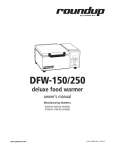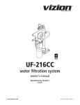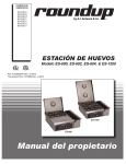
1
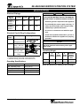
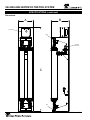
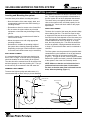
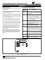
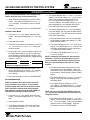
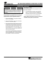
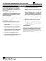
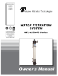
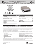
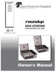
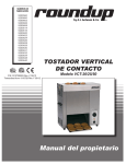
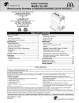
MANUFACTURING
NUMBERS:
9700501
9700505
9700508
9700512
WATER FILTRATION
SYSTEM
Model SE-4200/4400
P/N 1010852 Rev. C 04/06
Owner ’s Manual
SE-4200/4400 WATER FILTRATION SYSTEM
TABLE OF CONTENTS
Owner Information .....................................................2
General ......................................................................2
Warranty Information .................................................2
Service/Technical Assistance ....................................3
Important Safety Information ....................................3
Operating Specifications............................................5
Specifications .............................................................5
Electrical Ratings .......................................................5
Electrical Cord & Plug Configurations .......................5
Operating Weight.......................................................5
Dimensions ................................................................6
Installation...................................................................7
Unpacking ..................................................................7
Equipment Setup .......................................................7
Suggested Tools and Supplies for Installation ..........7
Locating and Mounting the system ...........................8
Filtration Process .................................................... 10
General
Operation...................................................................10
Operating Controls (Figure 2)................................. 10
Programming ...........................................................11
Operating the Unit .................................................. 15
Checking the Controller Program .......................... 16
Changing the Cartridges ........................................ 16
Maintenance ..............................................................16
Troubleshooting .......................................................17
Replacement Parts - SE-4200/4400.........................19
Wiring Diagram .........................................................21
Notes..........................................................................22
Notes..........................................................................23
LIMITED WARRANTY ...............................Back Cover
OWNER INFORMATION
Warranty Information
Antunes Filtration Technologies, a division of A.J.
Antunes & Co., has partnered with companies from
around the globe to produce the SE 4200/4400 water
filtration system. The SE 4200/4400 removes bacteria
and provides a substantial reduction of viruses that can
enter a typical water supply. This patented technology
is now available to you, sized for your particular application. All filter configurations utilize NeoH capillary
membranes, providing the latest innovation in reusable
surface filtration technology.
Please read the full text of the Limited Warranty in this
manual.
If the unit arrives damaged, contact the carrier immediately and file a damage claim with them. Save all
packing materials when filing a claim. Freight damage
claims are the responsibility of the purchaser and are
not covered under warranty.
The warranty does not extend to:
• Damages caused in shipment or damage as
result of improper use.
This manual provides the safety, installation, and operating procedures for the SE 4200/4400. We recommend that all information contained in this manual be
read prior to installing and operating the unit.
• Installation of electrical service.
• Normal maintenance as outlined in this manual.
Your SE 4200/4400 is manufactured from the finest
materials available and is assembled to AFT’s strict
quality standards. This unit has been tested at the factory to ensure dependable, trouble-free operation.
• Malfunction resulting from improper maintenance.
• Damage caused by abuse or careless handling.
• Damage from moisture into electrical
components
• Damage from tampering with, removal of, or
changing any preset control or safety device.
IMPORTANT! Keep these instructions for future reference. If the unit changes ownership, be sure this manual accompanies the equipment.
2
P/N 1010852 Rev. C 04/06
SE-4200/4400 WATER FILTRATION SYSTEM
Service/Technical Assistance
Purchased From:
If you experience any problems with the installation
or operation of your unit, contact Antunes Filtration
Technologies at 1-630-784-1000 or toll free in the
United States at 1-800-253-2991.
Date of Purchase:
Model No.:
Serial No.:
Fill in the information in the next column and have it
handy when calling for assistance. The serial number
is on the specification plate on the unit.
Mfg. No.:
IMPORTANT
A.J. Antunes & Co. reserves the right to change specifications and product design
without notice. Such revisions do not entitle the buyer to corresponding changes,
improvements, additions, or replacements for previously purchased equipment.
IMPORTANT SAFETY INFORMATION
Throughout this manual, you will find the following safety words and symbols that signify important safety issues with
regards to operating or maintaining the equipment.
In addition to the warnings and cautions in this manual,
use the following guidelines for safe operation of the
unit.
WARNING
GENERAL WARNING. Indicates information important to the proper operation of
the equipment. Failure to observe may
result in damage to the equipment and/or
severe bodily injury or death.
• Read all instructions before using equipment.
• For your safety, the equipment is furnished with
a properly grounded cord connector. Do not
attempt to defeat the grounded connector.
• Install or locate the equipment only for its intended use as described in this manual. Do not use
corrosive chemicals in this equipment.
CAUTION
• Do not operate this equipment if it has a damaged cord or plug, if it is not working properly, or
if it has been damaged or dropped.
GENERAL CAUTION. Indicates information important to the proper operation of
the equipment. Failure to observe may
result in damage to the equipment.
• This equipment should be serviced by qualified
personnel only. Contact the nearest Authorized
Service Agency for adjustment or repair.
• Do not block or cover any openings on the unit.
WARNING
• Do not immerse cord or plug in water.
• Keep cord away from heated surfaces.
ELECTRICAL WARNING. Indicates information relating to possible shock hazard.
Failure to observe may result in damage
to the equipment and/or severe bodily
injury or death.
P/N 1010852 Rev. C 04/06
• Do not allow cord to hang over edge of table or
counter.
3
SE-4200/4400 WATER FILTRATION SYSTEM
IMPORTANT SAFETY INFORMATION (continued)
The following warnings and cautions appear
throughout this manual and should be carefully
observed.
• Turn the unit off, disconnect the power
source, and allow unit to cool down before
performing any service or maintenance on the
unit.
• The equipment should be grounded according to local electrical codes to prevent the
possibility of electrical shock. It requires a
grounded receptacle with separate electrical
lines protected by fuses or a circuit breaker of
the proper rating.
Do not modify the power supply cord plug.
If it does not fit the outlet, have a proper
outlet installed by a qualified electrician.
-
Do not use an extension cord with this
appliance.
-
Check with a qualified electrician if you
are in doubt as to whether the appliance is
properly grounded.
• If the supply cord is damaged, it must be
replaced by the manufacturer or its service
agency or a similarly qualified person.
• This equipment is to be installed to comply
with the local plumbing code and any other
applicable code.
• All electrical connections must be in accordance with local electrical codes and any
other applicable codes.
• Water pressure must not exceed the membrane burst pressure of 7 bar (100 psi). To
reduce water pressure, install a water pressure regulator and set the water pressure to
suit application. Note that trans membrane
pressure (inlet water pressure) must be .5 - 2.5
bar (7 - 36 psi).
• WARNING, ELECTRICAL SHOCK HAZARD.
FAILURE TO FOLLOW THESE INSTRUCTIONS
COULD RESULT IN SERIOUS INJURY OR
DEATH.
-
-
Electrical ground is required on this appliance.
4
P/N 1010852 Rev. C 04/06
SE-4200/4400 WATER FILTRATION SYSTEM
SPECIFICATIONS
Electrical Ratings
Voltage
Watts Amps Hertz
SE-4200
9700501 &
9700505
120
150
1.25
50/60
SE-4400
9700508 &
9700512
230
150
.75
50/60
Model &
Mfg. #
WARNING
ELECTRICAL SHOCK HAZARD. FAILURE TO
FOLLOW THE INSTRUCTIONS IN THIS MANUAL
COULD RESULT IN SERIOUS INJURY OR DEATH.
Electrical Cord & Plug Configurations
Letter
Code*
Description
C
Commercial Cord
Configuration
CEE 7/7, 16
Amp., 250 VAC
(Assembly Only).
(C)F***
5-15P, 15 Amp.,
120 VAC., Non –
Locking (Assembly
Only).
•
Do not modify the power supply cord plug. If
it does not fit the outlet, have a proper outlet
installed by a qualified electrician.
•
Do not use an extension cord with this appliance.
•
Check with a qualified electrician if you are in
doubt as to whether the appliance is properly
grounded.
Operating Weight
GRN
WHT BLK
* Used in Model Designation
** Indicates the Plug comes with a Harmonized Cord
*** Indicates the Plug comes with a Commercial Cord
Operating Specifications
Max. Operating Pressure
7 bar (100 psi)
Max. Operating Temp.
40°C (104°F)
pH Range
1-13
Trans Membrane Pressure
0.5-3 Bar (7.25-43.5 psi)
MWCO
100 kd
P/N 1010852 Rev. C 04/06
Electrical ground is required on this appliance.
CAUTION
All electrical connections must be in accordance
with local electrical codes and any other applicable codes.
Harmonized Cord
(H)C**
•
Unit
A
Width
(inches)
B
C
Operating
Depth
Height
Weight
(inches) (inches (w/water)
(lbs)
SE-4200
12
14
49.75
93
SE-4400
12
14
69.75
127
NOTE: See Dimensions drawing on the next page.
5
SE-4200/4400 WATER FILTRATION SYSTEM
SPECIFICATIONS (continued)
Dimensions
A
B
Control Box
Drain
Permeate
(use water)
C
Inlet
6
P/N 1010852 Rev. C 04/06
SE-4200/4400 WATER FILTRATION SYSTEM
INSTALLATION
When making a plumbing connection to the system,
remember to use a back-up wrench on the support
plumbing. Always use a good quality and approved
pipe sealant or Teflon tape on pipe threads.
Unpacking
The carton should contain the filtration system and an
information packet.
• SE-4200 or SE-4400
• Information Packet
Be careful not to get the pipe sealant inside the pipe
when making the connections. Do not over tighten the
connections.
1. Remove unit and all packing materials from shipping carton.
It is recommended that plastic fittings be used when
connecting to the plastic connections of the system.
This will reduce the possibility of cracking the connections due to over tightening. If soldered plumbing is
used, do not apply heat to, or near, the filtration system.
2. Remove all packing materials and protective coverings from the unit.
2. Remove the information packet. To prevent delay
in obtaining warranty coverage, fill out and mail
the warranty card.
The use of union (O-ring seal) connections is highly
recommended for ease of installation and future servicing.
NOTE: If any parts are missing or damaged, contact Antunes Filtration Technologies IMMEDIATELY
at 1-800-253-2991 (toll free in the U.S.) or 630-7841000.
Suggested Tools and Supplies for
Installation
The following tools and supplies are suggested to make
the installation easier:
Equipment Setup
GENERAL
• Screwdriver
• Drill with bits
• Strap wrench
(up to 6” diameter)
• Tape measure
• Two gallon bucket
• Fresh 5 1/4% liquid chlorine bleach
(such as Clorox®)
When placing the unit into service, pay attention to the
following guidelines.
• Make sure power to the unit is off.
• Do not immerse the power cord or plug in water.
• Keep power cord away from heated surfaces.
ELECTRICAL
Ensure that the line voltage corresponds to the stated
voltage on the units specification label. Make sure
that the plug on the power cord from the system and
the outlet match. For proper operation of the system,
and to ensure the highest quality of water from the system, make sure that the system is not connected to a
switched electrical outlet.
CAUTION
Water Pressure must not exceed 7 bar (100 psi).
To reduce water pressure, install a water pressure
regulator and set water pressure to suit application. Note that the trans membrane pressure
must be .5 - 3 bar (7.25 - 43.5 psi).
PLUMBING
NOTE: This unit is designed to use tap water not to
exceed 104º F (40º C).
The SE Series uses the following connections:
P/N 1010852 Rev. C 04/06
Adjustable wrenches
Pipe wrenches
Level
Pipe dope or Teflon
tape
CAUTION
This equipment is to be installed to comply with
the basic plumbing code of the Building Officials
and Code Administrators, INC. (BOCA) and the
Food Service Sanitation Manual of the Food and
Drug Administration (FDA).
An ABC-type fuse (6 Amp, 250 VAC) is located inside
the control box.
• Water Inlet (Feed Water)
• Permeate (Product Water)
• Drain
•
•
•
•
3/4” NPT
3/4” NPT
3/4” NPT
7
SE-4200/4400 WATER FILTRATION SYSTEM
INSTALLATION (continued)
Locating and Mounting the system
be installed in the water line after the permeate connection. This will help prevent possible contamination of
the filter system due to other equipment downstream.
The check valve (not supplied) should be mounted
close to the system outlet, and sized properly for the
plumbing line. Check with local codes for the proper
specification.
Consider these points before mounting the system:
• Note the location of the water supply, drain, and
an appropriate electrical outlet when choosing a
mounting location.
• Remember to allow for access to the Control Box.
DRAIN LINE PLUMBING
• Do not mount the system above any electrical
equipment or items that may be damaged if they
get wet.
The drain line is used to flush away the particle buildup
when cleaning the filter. The drain line must be able
to support the flow rate when the system flushes. The
flow rate from the flush depends on the inlet water pressure, inlet pipe size, and system selected. It is recommended that the drain line be as large as, or larger
than, the inlet plumbing line. The drain line should be
as short as possible, sloping downward without kinks
or loops. Be sure that the drain used is not blocked or
restricted.
• Install the system in a location that will allow for
future service access.
• Mount the system on a wall using appropriate
mounting hardware.
• Remember to consider the operating weight of
the system when choosing mounting hardware.
Depending on the type of wall on which the system
is mounted, wall reinforcement may be necessary.
The filter system must be protected from possible back
contamination by the installation of an air gap between
the drain connection of the system and the drain
(Figure 1). This gap in the line, with no physical contact
between the system and sewer, prevents contamination
of the system in the event of a backed-up sewer.
INLET WATER PLUMBING
It is recommended that the inlet water plumbing line
be 3/4” NPT or larger. A shutoff valve (not supplied)
should be installed in the line leading to the system.
The valve should be mounted close to the system inlet,
and sized properly for the inlet plumbing line. The system should only be connected to the cold water line.
NOTE: Make sure that the end of the drain line is
positioned and secured at least 2 inches above
the drain so that the water flow is directed into the
drain, without splashing (Figure 1).
PERMEATE LINE PLUMBING
To ensure the highest quality and safest water, it is
recommended that a check valve (to prevent backflow)
Secure
End
Drain Line from
System
Drain Line from
System
2”
minimum
Standpipe
Secure
End
2”
minimum
Floor
Drain
Drain
Figure 1. Proper Draining
8
P/N 1010852 Rev. C 04/06
SE-4200/4400 WATER FILTRATION SYSTEM
INSTALLATION (continued)
FLUSHING AND STARTING THE SYSTEM
SANITIZING THE SYSTEM AND LINES
To ensure that the highest quality water is produced
from the system, the plumbing leading from the filter
system must be flushed clear of all debris after the
system is hooked up. After making the connection to
the outlet of the filter system, open a faucet or tap closest to the filter system, then slowly open the inlet water
valve. Allow the pipe to flush until all debris is removed.
The plumbing must also be sanitized to eliminate possible contamination that may have occurred during the
installation process. Chlorine bleach can be used to
sanitize the plumbing. The amount of bleach to use
depends on the system being installed, and the amount
of plumbing downstream of the filter system. Generally,
1 or 2 cap fulls of bleach will be sufficient to sanitize
the system. This can be done before the system final
connections are made or after the system has been
installed and flushed.
The unit also must be flushed to remove air and the
shipping/storage solution. For maximum quality, the
permeate water produced during the flushing procedure
must be discarded. Direct this permeate water to drain.
1. Open the faucet or tap closest downstream to the
filter system.
CAUTION
Ingesting the protective solution may cause irritation of the gastrointestinal tract, colic, diarrhea, or
other similar symptoms
2. Close the inlet water valve and allow the system
to depressurize.
3. Place a bucket under the inlet connection to the
system. Disconnect the inlet pipe from the system. Water will flow out the pipe as the system
drains.
1. Plug the power cord into the appropriate electrical
outlet.
2. Follow the programming steps as outlined in the
Operation section of this manual.
CAUTION
Be careful when handling bleach. Follow all warnings and precautions on the bleach packaging.
Do not mix Bleach with any other cleansers or
sanitizers.
3. Open the tap or faucet closest downstream to the
filter system.
4. Slowly open the inlet water valve and allow water
to enter the system.
4. When the water flow out of the pipe stops, pour
the liquid bleach into the pipe. Reattach the
plumbing to the system inlet.
5. Press the Run button. The drain valves will open
to flush the air out of the center of the hollow
fibers. Check to make sure that the drain water is
directed into the drain without splashing.
5. Slowly open the inlet water valve to re-pressurize
the system. Allow water to flow out the tap until
the smell of bleach is present.
6. The drain valves will close automatically. Water
should continue to flow through the system and
out of the open tap. Allow water to flow out of the
tap for at least 15 minutes at maximum flow rate.
6. Close the tap and let the system stand with no
water flow for at least 15 minutes to allow the
bleach to sanitize the pipes.
7. After 15 minutes without flow, open the tap and
flush until the presence of bleach is gone. All
other taps should be opened to flush any bleach
from the plumbing.
7. Close the tap and let the system stand with no
water flow for 15 minutes to allow any trapped air
to come out of the hollow fibers. Check for leaks
at all fittings.
8. Close the tap. The sanitization is complete.
8. After 15 minutes without any flow, open the tap for
5 minutes to allow any trapped air to be flushed
out.
Program the other controller features following the
steps within the Operation section of this manual.
9. Close the tap. The flushing is complete.
P/N 1010852 Rev. C 04/06
9
SE-4200/4400 WATER FILTRATION SYSTEM
OPERATION
Filtration Process
Operating Controls (Figure 2)
The filtration process includes a Filtration Cycle and a
Backwash Cycle.
Control
Button
During the Filtration Cycle, water enters the system
inlet port and passes through the filter elements before
exiting via the Permeate outlet.
This system is designed so that no valves are powered
during the Filtration Cycle. This allows water to continue to be filtered during a power outage and it minimizes
electrical power consumption.
After a period of time, the filters have to be cleaned.
This is accomplished through the Backwash Cycle.
During the Backwash Cycle, filtered water from one of
the cartridges is fed back through the other cartridge to
break up any debris collected on the membrane walls.
The Backwash Cycle includes a forward flush step
which then uses the feed water to flush away the loosened debris from the cartridge’s membranes. The
valves are only powered during the flushing cycle and
in STOP MODE.
NOTE: Both the Filtration and Backwash cycles
can be completely automated through the Control
Panel. See the Programming section within this
manual.
Function
FLUSH
Performs a QUICK FLUSH operation
when actuated during FILTER MODE or
STOP MODE.
RUN
Initializes and starts an internal timer for
the automatic flushing of the system and
puts the system into FILTER MODE.
When pressed, the system performs a
BORE AIR RELEASE operation before
entering FILTER MODE.
STOP
Stops all functions immediately; powers all valves. Closes the Input and
Permeate ports/valves and opens all
Drain ports/valves.
F1
Starts the Backwash Cycle during
FILTER MODE or STOP MODE.
F2
Service Feature. Valve, Transducer,
and alarm status can be viewed and
changed. Press and hold this button for
a minimum of 3 seconds to access this
mode.
CURSOR
Up/Down/Left/Right arrow buttons
are used to scroll through the choices
shown in the Message Display window.
MENU
Allows access to program and setting
features .
ENTER
Used to confirm settings in MENU
mode.
Message Display
FLUSH
RUN
STOP
MENU
F1
F2
ENTER
Figure 2. Operating Controls
10
P/N 1010852 Rev. C 04/06
SE-4200/4400 WATER FILTRATION SYSTEM
OPERATION (continued)
Programming
Using the Up and Down arrow buttons, enter the
correct date in mm/dd/yy format. After each entry,
press the Enter button. For example, for June, set
the month as 06 and then press the Enter button.
Set the date and year in this same manner.
1. Once the system is connected to a power source,
the unit displays the following messages in the
table below in order:
Message
Description
ANTUNES FILTRATION
Rev. 00.00.00
Shows the software and
hardware revision information.
ver- BASIC ON:lcd ON
units- US:audio ON
Indicates the system hardware setup.
BORE AIR RELEASE
00:05 mm:ss
Indicates the unit is filling
filters with water.
STOP MODE
00/00/00 00:00:00 AM
Indicates the controller is
performing internal tests to
verify correct filter operation.
FILTER MODE
00/00/00 00:00:00 AM
Indicates the unit is in
FILTER MODE.
5 The system then displays the SET TIME message.
Using the Up and Down arrow buttons, enter the
correct hour in hh format and press the Enter button. Then, enter the correct minutes in mm format
and press the Enter button. Finally, select AM or
PM and press the Enter button.
6. After setting the date and time, the system displays the SET DATE/TIME message. If you need
to make a correction to your settings, you can
press the Enter button and make any changes. If
the settings are correct, press the Menu button to
return to the STOP MODE function. The correct
date and time should be displayed.
7. Press the Run button to return to the FILTER
MODE function.
After the system displays the FILTER MODE message,
proceed to the next step.
SET FILL FUNCTION MODE (BORE AIR RELEASE)
NOTE: Only a few items need to be programmed
to allow for the proper operation of the system.
Default values in the system programming are set
to automatically flush the filter cartridges for 1 minute every hour. Default values should be sufficient
for most locations’ filtration needs.
1. From the FILTER MODE display, press the Stop
button. The system displays the STOP MODE
message.
2. Press the Menu button.
NOTE: To skip a value, accept a default value, or to
save a changed value, you MUST press the Enter
button to save the entry and proceed to the next
option. If you make a mistake, press the Menu button to go back to the previous display.
3. Using the Up and Down arrow buttons, scroll from
SET PASSWORD to SET FILL FUNCTION. Press
the Enter button.
4. The system displays the BORE AIR RELEASE
message. The default time is displayed as
00:05 seconds, which should be sufficient for
most locations. To change this setting, use the
Up and Down arrow buttons and the Enter key
to make the change. For example, to change the
setting to six, press the Enter button until the cursor is in the fourth position and use the Up/Down
arrow buttons to change the setting to the desired
time.
SET DATE/TIME MODE
NOTE: The Date and Time must be set in order for
proper system operation.
1. If the system does not already display the SET
DATE/TIME message, from the FILTER MODE,
press the Stop button. The system enters STOP
MODE and displays STOP MODE on the display.
5. Next, the system displays the SET FILL
FUNCTION display. If you need to make a correction to the Fill Function setting, press the Enter
button to do so. If the setting is correct, Press
the Menu button to save the setting and return to
STOP MODE.
2. Press the Menu button.
3. Using the Up and Down arrow buttons, scroll from
SET PASSWORD to SET DATE/TIME and press
the Enter button.
4. The system displays the SET DATE message.
P/N 1010852 Rev. C 04/06
6. Press the Run button to return to FILTER MODE.
11
SE-4200/4400 WATER FILTRATION SYSTEM
OPERATION (continued)
SET FLUSH CYCLE MODE
SET QUICKFLUSH MODE
1. From the FILTER MODE display, press the Stop
button. The system switches to STOP MODE and
displays the STOP MODE display.
NOTE: The Quick Flush function allows the system to be used for water systems containing a
high quantity of air. Air does not pass through the
filtration membranes. Performing a quick flush
at pre-set times allows the accumulated air to be
released.
2. Press the Menu button.
3. Using the Up and Down arrow buttons, scroll from
SET PASSWORD to SET FLUSH CYCLE. Press the
Enter button.
1. From the FILTER MODE display, press the Stop
button. The system switches to STOP MODE and
displays the STOP MODE display.
4. The system displays the ACTIVATE FLUSH BY
display. Accept the default value of automatic.
2. Press the Menu button.
IMPORTANT
The ACTIVATE FLUSH BY setting should ALWAYS
be set to “automatic” unless instructed by the
manufacturer. If your system is in “manual”
mode, use the Left and Right arrow buttons to
set this value back to the “automatic” setting and
press the Enter button.
3. Using the Up and Down arrow buttons, scroll from
SET PASSWORD to SET QUICKFLUSH and press
the Enter button.
4. The system displays the QUICKFLUSH ENABLE
display. The default value is off. Use the Left
and Right arrow buttons to toggle between on and
off. When the value is set to on, press the Enter
button.
5. The system displays the FLUSH BY INTERVAL
display. The default value for this setting is on.
This setting should be appropriate for most locations. If desired, use the Left and Right arrow
buttons to change the setting to off. Press the
Enter button.
5. The system displays the QKFLUSH INTERVAL
display. The default interval value is 00:15 (or
fifteen minutes). This value should be appropriate for most locations. To change this value, use
the Up and Down arrow buttons to enter the time
interval in hours and minutes (hh:mm). After each
entry, press the Enter button.
If the FLUSH BY INTERVAL setting is set to on,
the system prompts for the interval setting. The
default interval is 001:00 (or one hour) in hhh:mm
format. To change this setting, use the Up and
Down arrow buttons to change the interval time.
After each entry, press the Enter button.
6. Next, the system displays the QKFLUSH LENGTH
display. The default length value is 00:15 (or fifteen seconds). Again, this should be appropriate
for most locations. To change this value, use the
Up and Down arrow buttons to enter the desired
flush interval in hours and minutes (mm:ss). After
each entry, press the Enter button.
If the FLUSH BY INTERVAL value is set to off,
press the Enter button. The system displays the
FLUSH BY TIME OF DAY message. The default
for this value is off. This should be changed to
on using the Right and Left arrow buttons. After
the entry is set to on, press the Enter button.
7. The system displays the SET QUICKFLUSH display. If you need to correct your settings, press
enter and reset the values accordingly. If the
information is correct, press the Menu button to
return to STOP MODE.
NOTE: If the FLUSH BY TIME OF DAY option is set
to “off,” the system displays the FLUSH BY PRESS
DIFF display. Step 6 will be necessary ONLY if the
FLUSH BY TIME OF DAY option is set to “on.”
8. Press the Run button to return to the FILTER
MODE display.
6. Next, the system prompts for the desired flush
time of day. Using the Up and Down arrow buttons, set the desired time of day for the system
flush in hh/mm and AM or PM. After each entry,
press the Enter button.
12
P/N 1010852 Rev. C 04/06
SE-4200/4400 WATER FILTRATION SYSTEM
OPERATION (continued)
RESET DEFAULTS MODE
7. The system displays the FLUSH BY PRESS DIFF
display. If the filtration system came with pressure
transducers installed, this feature is available.
If no transducers are installed, this feature is
ignored. The default value is on. This should be
appropriate for most locations. Use the Left and
Right Arrow Buttons to make the desired change
and then press the Enter button.
1. From the FILTER MODE display, press the Stop
button. The system displays the STOP MODE display.
2. Press the Menu button.
3. Using the Up and Down arrow buttons, scroll from
SET PASSWORD to RESET DEFAULTS and press
the Enter button.
NOTE: If the FLUSH BY PRESS DIFF option is set
to “off,” the system will then display the DEMAND
SENSOR display which is protected by a special
password. Leave the DEMAND SENSOR option
OFF and press the Enter button to go to the
PREFLUSH display. For more information on the
DEMAND SENSOR option, contact the manufacturer.
4. The system displays the ENTER PASSWORD display. The default password is AAAA. Use the Up
and Down arrow buttons to enter the password.
After each entry, press the Enter button.
If you enter the wrong password, the system will
display the ACCESS DENIED. PRESS ‘ENTER’ TO
CONTINUE message. Press Enter or wait and the
system will prompt you for the password again.
8. If the FLUSH BY PRESS DIFF setting is set to
on, the system will then prompt for a pressure
differential value. The default value is 21 psi,
which should be fine for most locations. To
change this value, use the Up and Down arrow
buttons to make a change. Then, press the Enter
button.
IMPORTANT
If you cannot remember your password, call
Technical Service immediately for assistance.
5. The system displays the TURN OFF POWER,
WAIT 10 SEC, RESTORE POWER message.
Unplug the power cord and wait for ten (10) seconds or more, and then plug the cord in again.
9. The system displays the PREFLUSH display. The
default value is on. This should suit most locations. To change this value, use the Left and
Right arrow buttons to select on or off. Press
the Enter button to accept the change (or to
accept the default value if a change is not made).
6. The system then cycles through initialization
displays and prompts you to set the Date and
Time. Follow the instructions in the Set Date/Time
Modes section of this manual. The system can
then be re-programmed as desired.
10. Regardless of the setting of the PREFLUSH
option, the system then displays the BACKWASH
LENGTH prompt. The default for this option is
00:20 seconds which should be fine for most
locations. Enter the desired length of time for the
backwash operation in mm:ss format. Press the
Enter button to accept the change (or to accept
the default value if a change is not made).
REVIEW OF CYCLES MODE
1. From the FILTER MODE display, press the Stop
button. The system displays the STOP MODE display.
2. Press the Menu button.
3. Using the Up and Down arrow buttons, scroll to
REVIEW OF CYCLES. Press the Enter button.
11. Next, the system displays the FORWARD FLUSH
LENGTH prompt. Enter the desired length of time
for the forward flush operation in mm:ss format.
The default value is 00:10 seconds, which should
be fine for most locations. Press the Enter button to accept the change (or to accept the default
value if a change is not made).
4. The system displays the REVIEW HISTORY display. The default value is off. Use the Left
and Right arrow buttons to toggle between off
and on. With the setting set to on, use the Up
and Down arrow buttons to view a history of
keystrokes with date and time information. This
information can be used to determine causes of
problems or assist in servicing the system.
12. The system displays the SET FLUSH CYCLE display. If you need to correct any settings, press
enter and make the desired changes. If changes
are not necessary, press the Menu button to
return to the STOP MODE display.
13. Press the Run button to return to FILTER MODE.
P/N 1010852 Rev. C 04/06
13
SE-4200/4400 WATER FILTRATION SYSTEM
OPERATION (continued)
NOTE: The REVIEW HISTORY mode displays information about the most recent operation first.
5. The system displays the SET ENABLE PASSWORD
display. The default setting is off. If you do not
want to use a password, press the Enter button. The system will then display the SELECT
LANGUAGE display. The default setting is English
(other languages are not available at this time).
Press the Enter button to accept the default.
5. When finished reviewing history, press the Enter
button. The system will display the REVIEW OF
CYCLES display. Press Menu to return to STOP
MODE.
6. Press the Run button to return to FILTER MODE.
6. The system displays the SET PASSWORD display.
From this display, you can press the Menu button
to exit this mode. If you DO choose to set a password, follow these steps.
INTERNAL TESTS MODE
1. From the FILTER MODE display, press the Stop
button. The system displays the STOP MODE display.
a. Press the Enter button, use the Left and Right
arrow buttons to change the setting to on, and
press the Enter button.
2. Press the Menu button.
b. The system displays the SET NEW PASSWORD?
prompt. The default value is off. Use the Left
and Right arrow buttons to switch the value to
on, and press the Enter button.
3. Using the Up and Down arrow buttons, scroll from
SET PASSWORD to INTERNAL TESTS and press
the Enter button.
4. In this mode, valve, sensor, and alarm status can
be viewed and changed. Use the Up and Down
arrow buttons to view the different settings. Use
the Left and Right arrow buttons to toggle different
options on and off.
c. The system then displays the ENTER NEW
PASSWORD prompt.
NOTE: Passwords are limited to 4 alpha-numeric
characters. Think of a password that is easy for
you to remember but difficult for others to guess.
Write your password down and store it in a safe
location.
IMPORTANT
This feature is ONLY to be used for servicing the
system or to diagnose problems.
d. Use the Up and Down arrow buttons to enter
each character of your password. When the
character is correct, press Enter to move to the
next character. When finished, press the Enter
button.
5. To exit this mode, press the Menu button. The
system will display the INTERNAL TESTS display.
Press the Menu button to return to the STOP
MODE display.
6. Press the Run button to return to FILTER MODE.
e. The system displays the RE-ENTER PASSWORD
display. Enter your new password again as
described above.
SET PASSWORD MODE
NOTE: A password does NOT need to be set for
proper operation of the system. The password
function should ONLY be used to protect the time,
flush, and feature settings from being changed.
After setting a password, that password MUST be
used before accessing any Menu features.
f. The system will then display the PROTECT
KEYS display. The default value is off. Accept
this setting with the default value by pressing
Enter.
NOTE: Do not set the PROTECT KEYS function to
“on.” Contact the manufacturer for instructions on
using this function.
1. From the FILTER MODE display, press the Stop
button. The system displays the STOP MODE display.
g. The system then returns to the SET LANGUAGE
display. Press the Enter button to return to the
SET PASSWORD display. Then, press the Menu
button to return to STOP MODE. Press the
Run Button to return to FILTER MODE.
2. Press the Menu button.
3. If not already displayed, use the Up and Down
arrow buttons to scroll to SET PASSWORD, and
press the Enter button.
14
P/N 1010852 Rev. C 04/06
SE-4200/4400 WATER FILTRATION SYSTEM
OPERATION (continued)
Operating the Unit
WARNING
Once a password has been activated, that password will be required to change any settings. DO
NOT lose your password! Keep it in a safe place.
Contact the manufacturer if you have lost your
password.
After all of the menus have been programed, the system can be activated.
1. To start the filtration operation, press the RUN
button. The system will perform a BORE AIR
RELEASE function and return to FILTER MODE.
When a password is actively protecting the system, you
will be prompted for that password any time you press
the Menu button. Follow these steps to access Menu
options when the system is password protected.
2. To stop any function, press the STOP button.
NOTE: With the STOP button pressed, all valves are
activated and the system is pressure free.
1. Press the Stop Button. The system will display
the STOP MODE display.
2. Press the Menu Button. The system will display
the ENTER PASSWORD display.
3. Use the Up and Down arrow buttons to enter the
first character of your password and then press
the Enter button. Repeat until the password has
been selected and press the Enter button. The
system displays the SET PASSWORD display. You
may now scroll to your desired menu option and
make any desired changes.
If you enter the wrong password, the system will
return to Stop Mode. Press the Menu button to
enter the password again. If you have forgotten
your password, contact the manufacturer.
P/N 1010852 Rev. C 04/06
15
SE-4200/4400 WATER FILTRATION SYSTEM
MAINTENANCE
The SE-4200/4400 Filtration system is designed to
require very little maintenance. To ensure that the
water is of the highest quality, occasionally some service is required.
6. Inset the new cartridge into the system
Checking the Controller Program
8. Inspect the O-rings to make sure they are clean
and are not splitting or cut. For all O-rings, make
sure they are lubricated with an approved food
grade lubricant acceptable for drinking water use.
7. Attach the Permeate Port connection to the new
cartridge.
The program features and setting should be checked
occasionally to confirm that the system is operating
under the proper settings.
9. For each End Cap, position the cartridge and cap
and screw the cap to the cartridge. Tighten with
strap wrench, if necessary.
Follow the procedures outlined in the Operation section
of this manual to check and set the controller settings.
Changing the Cartridges
10. Repeat this procedure for the other cartridge.
While the filtration system is designed for long life,
eventually the cartridges will need to be replaced.
11. Follow the Flushing and Starting up the System
and Sanitizing the System and Lines Procedures
in the Installation section of this manual to complete the cartridge change.
.1 Open the faucet or tap closest downstream to the
filtration system.
SYSTEM SANITATION
2. Press the Stop button or close the Inlet Water
Valve and allow the system to depressurize.
Over time and use, the plumbing downstream from the
system may require sanitization. It is recommended
that the system and downstream plumbing be sanitized at least once a year. When necessary, follow
the Sanitizing the System and Lines procedure in the
Installation section of this manual.
3. Place a bucket under the filter cartridge to be
changed. Using a strap wrench, loosen, but DO
NOT remove the top and bottom End Caps.
4. Disconnect the Permeate Port connection.
5. Unscrew the cartridge End Caps from the cartridge, slide the caps past the cartridge ends, and
remove the old cartridge from the system.
16
P/N 1010852 Rev. C 04/06
SE-4200/4400 WATER FILTRATION SYSTEM
TROUBLESHOOTING
Problem
Possible Cause
Unit does not have power.
The power cord is not correctly plugged
in.
Plug power cord in correctly.
The Control Display is
blank.
The power cord is not correctly plugged
in.
Plug power cord in correctly.
Control Board is inoperable.
Transformer is inoperable.
Contact your maintenance person or
Authorized Service agency.
Unit in “STOP” mode
Set unit to “RUN” mode.
Optional Inlet Valve (if installed) is
closed.
Open Inlet Valve.
No water comes out of the
filter system.
Corrective Action
Optional Prefilter (if installed) is plugged. Clean/replace Prefilter.
Optional Check Valve (if installed) is
stuck closed.
Clean/replace Check Valve.
End of capillaries plugged.
Clean/replace cartridge.
Valve/Controller Malfunction.
Replace Valve(s)/ Controller.
See above.
See above.
System is flushing.
Wait for flush cycle to end.
Flushing program set incorrectly for
water conditions.
Decrease the Flush interval and increase
the flush duration.
Drain valve(s) stuck open.
Replace/rebuild valve(s).
Low inlet water pressure.
Boost pressure/replace pipes.
Storage/Shipping solution not completely flushed out.
Flush system longer.
Biological growth in pipes.
Sanitize plumbing.
Water conditions have changed.
Consider installing a taste and odor filter.
Broken Capillary in cartridge
Replace cartridge.
Drain Valve(s) stuck open.
Replace/rebuild valve(s).
Controller sending continuous signal to
valve(s).
Replace Controller.
Flush runs too long.
Program duration set too long.
Change flush duration.
Flush occurs at time of
high water usage.
Interval flush set to interfere with high
water usage.
Change interval program time, or consider
time of day flush.
Time of day flush set to interfere with
high water use.
Chance time of day for flush to non-peak
water usage time.
Water splashes at drain
during flush.
Drain line not positioned properly.
Reposition end of drain line.
Water leaks at ends of
cartridge after changing
cartridge.
Cartridge end connections not tight.
Tighten with strap wrench if necessary.
O-rings not lubricated.
Lubricate O-ring with a food-grade lubricant.
O-rings split, cut, or twisted.
Replace O-rings.
Low water flow/pressure
out of system.
Water tastes bad.
Flush runs continuously.
P/N 1010852 Rev. C 04/06
17
SE-4200/4400 WATER FILTRATION SYSTEM
TROUBLESHOOTING (continued)
Problem
Water leaks from
Permeate Port.
Water leaks from system
fitting or connection.
Possible Cause
Corrective Action
Permeate Port not tight.
Tighten with strap wrench if necessary.
O-rings not lubricated.
Lubricate O-rings with food-grade lubricant.
O-rings split, cut, or twisted.
Replace O-rings.
Not enough pipe thread sealant used.
Redo fitting with proper amount of sealant.
Fitting loose or broken.
Retighten or replace fitting.™
18
P/N 1010852 Rev. C 04/06
SE-4200/4400 WATER FILTRATION SYSTEM
REPLACEMENT PARTS - SE-4200/4400
22
22a
21
25
47
23
26
28
29
65
30
See Inset A
33
47
47a
34
36
32
35
37
48
31
38
39
40
41
42
8
9
11
Inset A
10
12
13
14
43
45
1
2
16
15
18
17
5
20
P/N 1010852 Rev. C 04/06
19
SE-4200/4400 WATER FILTRATION SYSTEM
REPLACEMENT PARTS - SE-4200/4400 (continued)
Item
Part
No.
1
2
5
1001073
5550100
7000434
6* 304P113
8* 308P151
9 4060376
10 4010187
11 4060375
12* 306P113
13 4060378
14 4060361
15 0503876
16 0400329
17 4010200
18* 308P103
20 5550101
21 0021461
22* 325P109
22a* 3250154
23 0400330
25 0503996
26 2190127
28 0011991
29 7000405
30 7000406
7000407
31 2190130
32 2190132
33 2190139
2190131
Description
Label Control Panel
Enclosure Control-upper
SE Series 3 Board Controller
Replacement Kit
Screw, FLTHD #4-40 x 1 15/16”
Sems Screw #8-32 X 5/16
Fuse 6 Amp-250vac
Transformer 230v/12v
Fuse Block 1-pole
6-32 x 0.1875 Slotted Truss Head
Block Terminal-6 Pole
Bus Bar Contact (4 Pole)
Bracket Transformer
Rubber Grommet
Transformer 115/230-24vac
Scr Mach #8-32 X 3/8” Sltrshd
Control Enclosure-lower
Inlet/Drain Bracket Weldment
Screw Hexcap 1/4-20 X 1/2”
Lock Washer, 1/4”
Bushing Snap 1 1/8”
Clamp Inlet/drain
Union End Cap
End Cap Union Connector Assy.
O-Ring Replacement Kit
4200 Cartridge Replacement Kit
4400 Cartridge Replacement Kit
Tee 3/4” Npt
Nipple 3/4” Npt X 5” Lg
Adaptor 1 1/2” To 3/4” Npt (SE-4400)
Adaptor 1 1/4” to 3/4” NPT (SE-4200)
Qty.
Item
1
1
1
34
35
36
37
38
39
40
4
8
1
1
1
2
1
2
1
2
1
6
1
1
12
12
2
2
4
4
1
1
1
6
2
2
2
20
Part
No.
Description
Qty.
2190141 Union Adaptor 3/4”
2190124 Nipple 3/4” Npt
0504007 Clamp Permeate
2190126 90° Elbow 3/4” Npt
0504006 Bracket Permeate
4060304 Terminal Block 3-pole
0700634 Power Cord-intl/harmonized
0700463 Power Cord Domestic
41 0400251 Strain Relief - Cord Connector
42 0504039 Bracket Mounting-40” Cartridge
43 4060377 Cable Tie Mount W/adhesive
44 2070117 Nipple Close 3/4” Npt
45 0504042 Plate Cover
47 4040171 N.O. Solenoid Valve-3/4” Npt
47a 4040172 N.C. Solenoid Valve 3/4”
48* 310P178 Screw Hex Bolt #10-32 X 3/8
49 2190135 Plug Pipe 3/4” Npt
52 1001080 Label Wiring Diagram
53 0700646 Wire Harness SE-4400
0700644 Wire Harness SE-4200
0700619 Wire Set Addendum 120 V
0700622 Wire Set Addendum 230 V
54* 306P103 Screw Mach 6-32 X 3/8” Lg Sltrshd
55 0400138 Lock-nut Conduit-1/2” Npt
56* 306P123 Screw Mach #6-32 X 7/8” Slrndhd
57* 306P101 Nut Hex #6-32
58* 308P103 Scr Mach #8-32 X 1/4” Sltrshd
64* 308P185 Screw Tap #8 X 3/8”
65 1001130 Label Filter Cartridge
66**5550102 Bag, Hardware Control Enclosure
*Only available in packages of ten.
** Not Shown
2
6
1
2
1
1
1
1
1
1
5
4
1
3
2
12
2
1
1
1
1
1
1
1
2
2
12
4
1
1
P/N 1010852 Rev. C 04/06
SE-4200/4400 WATER FILTRATION SYSTEM
WIRING DIAGRAM
P/N 1010852 Rev. C 04/06
21
SE-4200/4400 WATER FILTRATION SYSTEM
NOTES
22
P/N 1010852 Rev. C 04/06
SE-4200/4400 WATER FILTRATION SYSTEM
NOTES
P/N 1010852 Rev. C 04/06
23
LIMITED WARRANTY
Equipment manufactured by Antunes Filtration Technologies, Division of A.J. Antunes & Co. has been
constructed of the finest materials available and manufactured to high quality standards. These units
are warranted to be free from mechanical and electrical defects for a period of one year from date of
purchase or 18 months from shipment from factory, whichever occurs first, under normal use and service, and when installed in accordance with manufacturer’s recommendations.
To insure continued proper operation of the units, follow the maintenance procedure outlined in the
Owner’s Manual.
1.This warranty does not cover cost of installation, defects caused by improper storage or handling prior to
placing of the equipment. This warranty does not include overtime charges or work done by unauthorized
service agencies or personnel. This warranty does not cover normal maintenance, calibration, or regular
adjustments as specified in operating and maintenance instructions of this manual, and/or labor involved
in moving adjacent objects to gain access to the Equipment. This warranty does not cover consumable
items such as filtration membranes. This warranty does not pay travel, mileage, or any other charges
for an authorized service agency to reach the equipment location.
2.Antunes Filtration Technologies reserves the right to make changes in design or add any improvements
on any product. The right is always reserved to modify equipment because of factors beyond our control
and government regulations. Changes to update equipment do not constitute a warranty charge.
3.If shipment is damaged in transit, the purchaser should make a claim directly upon the carrier. Careful
inspection should be made of the shipment as soon as it arrives and visible damage should be noted
upon the carrier’s receipt. Damage should be reported to the carrier. This damage is not covered under
this warranty.
4.Warranty charges do not include freight or foreign, excise, municipal or other sales or use taxes. All such
freight and taxes are the responsibility of the purchaser.
5.THIS WARRANTY IS EXCLUSIVE AND IS IN LIEU OF ALL OTHER WARRANTIES, EXPRESSED OR
IMPLIED, INCLUDING ANY IMPLIED WARRANTY OR MERCHANTABILITY OR FITNESS FOR A PARTICULAR PURPOSE, EACH OF WHICH IS HEREBY EXPRESSLY DISCLAIMED. THE REMEDIES
DESCRIBED ABOVE ARE EXCLUSIVE AND IN NO EVENT SHALL ROUNDUP BE LIABLE FOR SPECIAL CONSEQUENTIAL OR INCIDENTAL DAMAGES FOR THE BREACH OR DELAY IN PERFORMANCE OF THIS WARRANTY.
A.J. Antunes & Co.
Headquarters/Manufacturing
180 Kehoe Boulevard
Carol Stream, Illinois 60188 USA
Phone (630) 784-1000
Toll Free (800) 253-2991
Fax: (630) 784-1650
Antunes Equipment
Manufacturing (Suzhou) Ltd.,
9 Hou Ju Road, Building #24,
S&T Park, SND
Suzhou, Jiangsu, China 215011
Phone: 86-512-6841-3637
Fax: 86-512-6841-3907
www.ajantunes.com