1
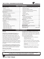
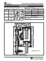
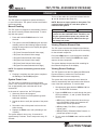
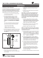
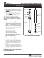
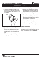
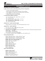
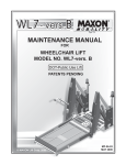
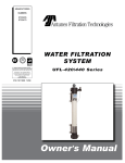
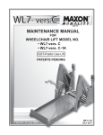
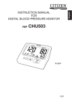
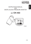
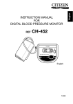
MANUFACTURING
NUMBERS:
9700800
9700810
9700820
9700830
9700840
9700850
Cartridge Tested and Certified by NSF
International against NSF/ANSI
Standard 42 and 53 for the reduction of:
Standard No. 42: Aesthetic Effects
Nominal Particulate Reduction Class I
Standard No. 53: Health Effects
Cyst Reduction
Turbidity Reduction.
TOTAL ASSURANCE
PACKAGE
TAP-400 Series
P/N 1010942 10/06
Owner ’s Manual
TAP (TOTAL ASSURANCE PACKAGE)
TABLE OF CONTENTS
Owner Information .....................................................2
General ......................................................................2
Warranty Information .................................................2
Service/Technical Assistance ....................................3
Important Safety Information ....................................3
Specifications .............................................................5
Electrical Cord & Plug Configurations .......................5
Dimensions - TAP-442...............................................5
Replacement Cartridges ............................................5
Performance Data Sheet ............................................7
Filter Cartridge Capacities .........................................7
System Capacities .....................................................7
Water Condition Equipment Guidelines...................7
Performance Claims for Percent Reduction ..............7
Installation...................................................................8
System Overview.......................................................8
Unpacking ..................................................................8
Equipment Setup .......................................................9
Mounting the System .............................................. 10
Attaching the Check Valve Assembly ......................11
Attaching the Drain Hosing......................................11
Attaching the Rinse Hose ........................................11
Attaching to the System Inlet ................................. 12
Attaching to the Filtered Water Permeate Outlet ... 12
Starting the System ................................................ 12
Rinsing the Ultrafilter Cartridge .............................. 13
Rinsing the Carbon Elements and Plumbing ......... 14
Sanitizing the System and Lines ............................ 14
Operation ................................................................ 15
Manual Flushing ..................................................... 15
System Power Loss ............................................... 15
Operation...................................................................15
Viewing Filtration Element Data ............................. 15
Viewing Sensor Readings ...................................... 15
Replacing Carbon Elements................................... 16
Maintenance ..............................................................16
Replacing the Ultrafilter Cartridge .......................... 17
System Sanitization ................................................ 18
Accessing TAP Controller Features........................ 19
Service Menu Access ............................................. 20
Troubleshooting .......................................................21
Wiring Diagram .........................................................23
Recommended Equipment Schematic ...................23
Replacement parts ...................................................24
Limited Warranty ......................................Back Cover
OWNER INFORMATION
General
If the system arrives damaged, contact the carrier
immediately and file a damage claim with them. Save
all packing materials when filing a claim. Freight damage claims are the responsibility of the purchaser and
are not covered under warranty.
The warranty does not extend to:
Antunes Filtration Technologies, Division of A.J.
Antunes & Co., has partnered with companies from
around the globe to produce the Total Assurance
Package (TAP) Series water filtration systems. The
TAP Series is an innovative filtration system that uses
NeoH capillary membranes as well as carbon element
to provide the latest innovation in filtration technology.
• Damages caused in shipment or damage as
result of improper use.
• Installation of electrical service.
This manual provides the safety, installation and
operating procedures for the TAP-Series water filtration
systems. We recommend that all information contained
in this manual be read prior to installing and operating
the system.
• Normal maintenance as outlined in this manual.
• Malfunction resulting from improper maintenance.
• Damage from moisture leaking into electrical
components.
Your TAP-Series system is manufactured from the finest materials available and is assembled to AFT’s strict
quality standards. This system has been tested at the
factory to ensure dependable trouble-free operation.
• Normal maintenance as outlined in this manual.
• Damage from tampering with, removal of, or
changing any preset control or safety device.
Warranty Information
Please read the full text of the Limited Warranty in this
manual.
IMPORTANT! Keep these instructions for future reference. If the system changes
ownership, be sure this manual accompanies the equipment.
2
P/N 1010942 10/06
TAP (TOTAL ASSURANCE PACKAGE)
OWNER INFORMATION (continued)
Service/Technical Assistance
Purchased From:
If you experience any problems with the installation or
operation of your system, contact Antunes Filtration
Technologies at 1-630-784-1000, or toll free in the
United States at 1-800-253-2991.
Date of Purchase:
Model No.:
Serial No.:
Fill in the information in the next column and have it
handy when calling for assistance. The serial number is
on the specification plate located on the system.
Mfg. No.:
IMPORTANT
A.J. Antunes and Company reserves the right to change specifications and product
design without notice. Such revisions do not entitle the buyer to corresponding changes,
improvements, additions or replacements for previously purchased equipment.
IMPORTANT SAFETY INFORMATION
In addition to the warnings and cautions in this manual,
use the following guidelines for safe operation of the
system.
Throughout this manual, you will find the following
safety words and symbols that signify important
safety issues with regards to operating or
maintaining the system.
• Read all instructions before using equipment.
• Install or locate the equipment only for its intended use as described in this manual. Do not use
corrosive chemicals in this equipment.
WARNING
GENERAL WARNING. Indicates information important to the proper operation of
the equipment. Failure to observe may
result in damage to the equipment and/or
severe bodily injury or death.
• Do not operate this equipment if it has a damaged cord or plug; if it is not working properly, or
if it has been damaged or dropped.
• This equipment should be serviced by qualified personnel only. Contact Antunes Filtration
Technologies for repair.
WARNING
• Do not immerse cord or plug in water.
• Keep cord away from heated surfaces.
ELECTRICAL WARNING. Indicates information relating to possible shock hazard.
Failure to observe may result in damage
to the equipment and/or severe bodily
injury or death.
CAUTION
GENERAL CAUTION. Indicates information important to the proper operation of
the equipment. Failure to observe may
result in damage to the equipment.
P/N 1010942 10/06
3
TAP (TOTAL ASSURANCE PACKAGE)
IMPORTANT SAFETY INFORMATION (continued)
Protect from high temperatures or abrupt variation
in temperature
The following warnings and cautions appear throughout
this manual and should be carefully observed.
The maximum operating temperature is 104°F (40°C).
Avoid abrupt variations in temperature. Any temperature
variation should be made slowly.
• Disconnect the power source before performing
any service or maintenance on the system.
• All electrical connections must be in accordance
with local electrical codes and any other applicable codes.
Protect from rough handling or dropping
Mechanical damage, external breakage, and/or internal
breakage of the filter can result if the system is dropped
or bumped. Handle with care at all times during transportation and installation.
• WARNING ELECTRICAL SHOCK HAZARD.
FAILURE TO FOLLOW THESE INSTRUCTIONS
COULD RESULT IN SERIOUS INJURY OR
DEATH.
-
Do not modify the power supply cord plug. If
it does not fit the outlet, have a proper outlet
installed by a qualified electrician.
-
Do not use an extension cord with this appliance.
Protect from organic solvents and concentrated
acids
Prevent any and all contact of the membrane with
strong solvents, solvents containing chlorine, or concentrated acids. Do not use strong solvents or concentrated acids on any plastic parts of the filter system.
Examples of some solvents to avoid: acetone, methyl
acetate (nail polish remover); hexane (spot removers);
turpentine, toluene (paint thinners); dry cleaning solutions, insecticides.
• If the supply cord is damaged, it must be
replaced by the manufacturer or its service agent
or a similarly qualified person.
Protect from abrasive material
• This equipment is to be installed to comply with
the local plumbing code and any other applicable
code.
The membranes must be protected from abrasive
materials like shavings left in a pipe. Abrasive materials
in contact with the membrane can cause irreversible
damage to the membrane. All pipes must be flushed
clean before installing the filter. All plastic parts of the
filter system must be protected from sharp objects like
knives, sand paper or other tools. Cutting or nicking a
plastic part can weaken it and cause a leak. Do not use
abrasive cleansers on any plastic parts.
• Water pressure must not exceed the membrane
differential pressure of 45 psig (3.1 bar). To
reduce water pressure, install a water pressure
regulator and set the system inlet water pressure
to 45 psi (3.1 bar).
Protect from becoming dry
Protect from water hammer
If the membrane dries out, irreversible damage to the
membrane may result. Protect the filter from becoming
dry by keeping it wet and sealed at all times.
The system must be protected from shock, pressure
surges, or pulsation that may occur inside water pipes.
Water hammer occurs in pipes when a valve or faucet
shuts quickly. Install a water hammer arrestor (pressure
vessel containing compressed air separated from the
water by a diaphragm) to reduce pressure shock.
Protect from freezing
If the membrane freezes during operation or storage,
irreversible damage to the membrane and brittle cracking of the cartridge or housing may result.
Protect from direct sunlight or other UV sources
Avoid long-term exposure to direct sunlight or other UV
sources. The filter should be stored in a dark location.
4
P/N 1010942 10/06
TAP (TOTAL ASSURANCE PACKAGE)
SPECIFICATIONS
Replacement Cartridges
Electrical Cord & Plug Configurations
Kit Model
Number
Description
7000525
120 VAC.,
NEMA 1-15P,
500mA
7000524
7000523
Replacement Cartridge
Configuration
230 VAC.,
CEE 7/16,
500mA
Part Number
TAP-420 Series
Ultrafilter L-420
7000411
TAP-440 Series
Ultrafilter L-440
7000412
TAP-421, 441
Single pack Carbon
7000669
TAP-422, 442
Dual pack Carbon
7000670
CAUTION
All electrical connections must be in accordance
with local electrical codes and any other
applicable codes.
220 VAC.,
HKH-01,
500mA
Dimensions - TAP-442
24"
(61 cm)
30"
(76 cm)
16"
(41 cm)
37”
(94 cm)
38-1/2”
(98 cm)
51-1/2”
(131 cm)
NOTE: The TAP Series
system Depth is 13 inches.
Figure 1. Dimensions
P/N 1010942 10/06
5
TAP (TOTAL ASSURANCE PACKAGE)
SPECIFICATIONS (continued)
System
“Smart Controler”
Drain Solenoid
Valve (autmatic)
System Drain
Connection
Carbon
Element
Housing
Permeate
Solenoid
Valve Automatic
Rinse
Valve
(manual)
UFL
Ultrafiltration
Cartridge
Flow
Meter
Dual Check
Valve Assembly
with Outlet
Pressure Guage
Permeate
Tank
Differential
Pressure
Sensor
Outlet Valve
(manual)
Inlet
Valve
(manual)
System
Outlet
Carbon
Element
Housing
Inlet
Solenoid
Valve (automatic)
System
Inlet
Figure 1. TAP-442 System Components
6
P/N 1010942 10/06
TAP (TOTAL ASSURANCE PACKAGE)
PERFORMANCE DATA SHEET
Filter Cartridge Capacities
Maximum Operating Pressure
Maximum Operating Temp.
Minimum Operating Temp.
Maximum Membrane Differential
Pressure
pH Range
MWCO
Cartridge Tested and Certified by NSF
International against NSF/ANSI
Standard 42 and 53 for the reduction of:
100 psig (690 kPa)
104°F (40°C)
40° F (4° C)
Standard No. 42: Aesthetic Effects
Nominal Particulate Reduction Class I
Standard No. 53: Health Effects
Cyst Reduction
Turbidity Reduction
45 PSI (3.1 Bar)
3-10
100 kD
System Capacities
Model
Mfg. No.
Gal./Liters
Per Min.
(max)
TAP-420
9710800
TAP-421
9700810
Carbon
Element
Capacity
UF
Length
0
5 gal.
(19 liters)
60,000 gal.
(227,000 liters)
0
20 in.
(51 cm)
1
TAP-422
9700820
120,000 gal.
(454,000 liters)
2
TAP-440
9700830
0
0
TAP-441
9700840
10 gal.
(38 liters)
TAP-442
9700850
60,000 gal.
(227,000 liters)
Cartridge has been tested according to NSF/ANSI
Standard 42 and 53 for reduction of the substances
listed below. The concentration of the indicated substances in water entering the system was reduced to a
concentration less than or equal to the permissible limit
for water leaving the system, as specified in NSF/ANSI
42 or 53. While testing was performed under standard
laboratory conditions, actual performance may vary.
Number
of
Carbons
40 in.
(102 cm)
120,000 gal.
(454,000 liters)
Performance Claims for Percent Reduction
Substance
Influent
Challenge
Concentration
Reduction
Requirement
cyst1
minimum 50,000/L
99.95%
Turbidity
11+/1 NTU
≤ 0.5 NTU
Particulate Class I
Particles 0.5 to <
1µm
at least 10,000
particles /mL
85%
1
2
1
based on the use of microspheres or Cryptosporium parvum oocysts
NOTE: The NSF Information provided above applies
to the TAP system’s Ultra-Filter Cartridge.
WATER CONDITION EQUIPMENT GUIDELINES
The following table describes the required or recommended equipment to be used with your filtration system based
on the Inlet Water Pressure and Inlet Turbidity.
If your Inlet Water
Pressure (PSI) is...
And your Inlet
Turbidity (NTU) is...
Then the Additional Equipment required or recommended is...
Less than 45 psi
Less than 1 NTU
Required: No additional equipment.
Recommended: Inlet Water Strainer (180 micron/80 mesh screen)
Greater than 45 psi
Less than 1 NTU
Required: Pressure Regulator
Recommended: Inlet Water Strainer (180 micron/80 mesh screen)
Less than 45 psi
Greater than 1 NTU
Required: Inlet Water Strainer (180 micron/80 mesh screen)
Greater than 45 psi
Greater than 1 NTU
Required: Inlet Water Strainer (180 micron/80 mesh screen)
P/N 1010942 10/06
7
TAP (TOTAL ASSURANCE PACKAGE)
INSTALLATION
System Overview
The TAP System has two components that improve
the quality of the water. The first (UFL-420/440 ultrafilter) removes particulate material, cysts, bacteria, and
virus. The second (carbon elements) remove chlorine,
tastes and odors. The TAP system is designed to be
self-cleaning by use of solenoid valves, sensing components, and a Smart Controller.
Unpacking
Open the large box. It should contain the following components:
• Plate mounted TAP-400 Series system with UFL
cartridge installed
• One Dual Check Valve assembly with gauge
• Two clear Carbon Element Housings with
Carbon Elements installed
• One 20 foot coil of flexible hose
• One accessory bag containing filter wrench and
hose clamps
• Owner’s Manual
NOTE: The system is also shipped with the power
transformer selected at time of purchase.
Remove all packing materials and protective coverings
from the system.
Figure 2. TAP System
Remove the information packet. To prevent any delay in
obtaining warranty coverage, fill out and mail the warranty card.
NOTE: If any parts are damaged, contact Antunes
Filtration Technologies IMMEDIATELY at 800-2532991 (toll free in the U.S. and Canada) or 630-7841000.
8
P/N 1010942 10/06
TAP (TOTAL ASSURANCE PACKAGE)
INSTALLATION (continued)
Equipment Setup
If soldered plumbing is used, do not apply heat to, or
near, the filtration system. The use of union (O-ring
seal) connections is highly recommended for ease of
installation and future servicing.
GENERAL
When placing the system into service, pay attention to
the following guidelines:
SUGGESTED TOOLS AND SUPPLIES FOR INSTALLATION
• Do not immerse cord or plug in water.
The following tools and supplies are suggested to make
the installation easier:
• Keep cord away from heated surfaces.
ELECTRICAL
Ensure the line voltage corresponds to the stated voltage on the specification label. Make sure the plug on
the power cord matches the appropriate outlet. For
proper operation, and to ensure the highest quality
water, do not connect the system to a switched electrical outlet.
• Pipe Wrenches
The TAP system uses the following connections (Fig. 1):
When making a plumbing connection to the system,
use a back-up wrench on the supporting plumbing.
Always use a quality, approved pipe sealant or Teflon®
tape on pipe threads. Be careful not to get the pipe
sealant inside the pipe when making connections.
FLOW REGULATOR ASSEMBLY
The TAP system uses a Water Flow Regulator
Assembly that controls the flow of water into the unit.
This assembly consists of a white threaded male connector and a color-coded Flow Regulator. The unit
MUST be operated with the appropriate Water Flow
Regulator Assembly.
DO NOT over tighten the connections. Use plastic fittings when connecting to the plastic connections of the
system. This reduces the possibility of cracking the connections due to overtightening.
SYSTEM
TAP-440, 441, and 442 Units: Use a BLACK and
WHITE Water Flow Regulator Assembly (10 gpm gallons per minute)
System
Display
1
2
3
• Garden Hose, 3/4”
CAUTION
Water pressure must not exceed a membrane
differential pressure of 45 psig. To reduce water
pressure, install a water pressure regulator and
set the water pressure to 45 psi.
System Inlet
1/2” NPT
System Outlet (Product Water) 1/2” NPT
Drain
3/4” NPT
Rinse Outlet
3/4” GHT (Garden Hose)
CARBON
• Pipe dope or Teflon® tape
CAUTION
This equipment is to be installed to comply with
the basic plumbing code of the Building Officials
and Code Administrators, Inc. (BOCA) and the
Food Service Sanitation Manual of the Food and
Drug Administration (FDA).
NOTE: The system must be connected to the COLD
water line. Do not connect the system to the hot
water line.
ULTRAFILTER
• Level
• Two Gallon Bucket • Fresh 5-1/4% liquid chlorine
bleach (such as Clorox®)
NOTE: The TAP system is designed to use tap water
not to exceed 104°F (40°C) or 45 psig (310 kPa).
% REMAINING
• Adjustable Wrenches
• Drill with Bits
• Tape Measure
PLUMBING
•
•
•
•
• Screwdriver
TAP-420, 421, and 422 Units: Use a GREEN and
WHITE Water Flow Regulator Assembly (5 gpm)
VIEW
CAUTION
Water Flow Regulator Assemblies are NOT interchangeable. Operating the system with the wrong
Water Flow Regulator or without a regulator can
damage the system, cause personal injury, and
voids the warranty!
NON-PEAK TIME
WHEN NEEDED
SYSTEM
FLUSH
Figure 3. TAP System Control Panel
P/N 1010942 10/06
9
TAP (TOTAL ASSURANCE PACKAGE)
INSTALLATION (continued)
INLET WATER PLUMBING
CAUTION
Due to its weight and size, the TAP system should
be mounted by 2 or more individuals.
If desired, a “T” or Cross Fitting with cap or plug can be
installed between the Inlet Valve and the System Inlet.
This fitting can be used for draining and sanitizing the
system and downstream plumbing.
Mounting the System
Before mounting the TAP system, please consider the
items listed in Mounting Requirements.
The plumbing leading to the system must be flushed
clear of all debris before connecting to the system inlet.
Hold a bucket at the inlet water line and slowly open the
inlet water valve. Allow the pipe to flush until all debris
is removed.
MOUNTING REQUIREMENTS
•
The system must be mounted with sufficient access
for cartridge replacement. The TAP system is 30
inches wide, 51-1/2 inches tall, and 13 inches deep.
The system should be mounted as close to the ceiling as possible to allow proper access when changing cartridges.
•
The system must be mounted with mounting hardware capable of supporting 120 lbs or more of
weight.
•
The system must be mounted near an appropriate
electrical outlet.
•
The system must be mounted near a drain for
flushing operations.
•
The system must be installed in front of all consumable water filtration processes.
DRAIN LINE PLUMBING
The drain line is used to flush away the particle buildup
when cleaning the ultra filter.
The drain line must be able to support the flow rate
when the system flushes. The flow rate from the flush
depends on the inlet water pressure, inlet pipe size, and
system selected. The drain line should be as large or
larger than the inlet plumbing line. The drain line should
be as short as possible, sloping downward without
kinks or loops. Be sure the drain used is not blocked or
restricted.
Protect the system from possible back contamination by
installing an air gap between the drain connection of the
system and the drain (Figure 4). This gap in the line,
with no physical contact between the system and drain,
prevents contamination of the system in the event of a
backed-up drain.
The TAP System is pre-assembled to a back plate. The
back plate has mounting holes (16” and 24” on- center)
on the top and bottom. Be sure to use both top and
bottom mounting holes to support the weight of the
system. Some mounting holes are covered by the UFL
Cartridge. Plan your mounting accordingly..
NOTE: Make sure the end of the drain line is positioned and secured at least 2 inches above the
drain so that the water flow is directed into the
drain without splashing.
Secure
End
Drain Line
from System
Drain Line
from System
2” (5.1 cm)
minimum
Secure
End
Standpipe
2” (5.1 cm)
minimum
Floor
Drain
Drain
Figure 4. Proper Draining
10
P/N 1010942 10/06
TAP (TOTAL ASSURANCE PACKAGE)
INSTALLATION (continued)
Attaching the Check Valve Assembly
Attaching the Drain Hosing
The system is shipped with a Dual Check Valve assembly attached to the system outlet (Figure 5). This
assembly can be detached from the system for ease of
mounting, but must be reattached to the system after
mounting. Refer to Figure 4 and follow these steps:
The TAP System is shipped with a coil of flexible hose
(20 feet) designed to direct the Drain Valve Solenoid
water to the drain. Refer to Figure 6 and follow these
steps:
1. Cut the flexible hose (provided) so that the hose
reaches the drain from the appropriate valve.
1. Insert the Dual Check Valve assembly into the
System Outlet.
2. Connect one end of the hose to the barbed fitting
on the Drain Valve Solenoid and secure with one
of the provided hose clamps.
2. Make sure the Dual Check Valve assembly is fully
inserted into the System Outlet fitting.
NOTE: Do not remove the pipe nipple and the connected System Outlet Valve from the Dual Check
Valve assembly.
al C
Du
NOTE: The drain MUST be able to accommodate a
drain flow 10 gpm. The drain hose MUST have an
air gap between the end of the hose and the drain.
al
heck V ve Assem
bly
Check
Valve
Housing
Dual Check Valve Assy.
System Connection
(Note: Minimum Gap
3. Direct the other end of this hose to the drain.
Attaching the Rinse Hose
System
Connection
The TAP system has a standard 3/4” garden hose connection at the Rinse Valve. A 3/4” garden hose (not
supplied) long enough to reach from this connection to
the drain should be used for rinsing. Be sure to install a
gasket in the hose end before attaching to the system.
Pressure
Gauge
Outlet
Valve
1. Connect the end of the garden hose to the fitting
on the rinse valve and tighten. Use a back-up
wrench on the fitting if required.
2. Direct the other end of the hose to the drain.
Secure as necessary.
System
Outlet
NOTE: the drain MUST be able to accommodate a
flow of 10 gpm.
Figure 5 Dual Check Valve Assembly
3/4” Garden Hose
Connection
Secure Hose
with Worm
Clamp
Direct Hose
to Drain
Drain Solenoid Valve
Direct Hose
to Drain
Rinse Valve
Figure 6 Attaching the Drain Hose
P/N 1010942 10/06
11
3/4” Garden Hose
(Not Supplied)
TAP (TOTAL ASSURANCE PACKAGE)
INSTALLATION (continued)
Attaching to the System Inlet
CAUTION
Do not use the Rinse Valve connection for consumable water. Because the Carbon Elements are
after the Rinse Valve, the Rinse Valve water may
have an objectionable taste.
The System Inlet (Figure 7) has a 1/2” NPT female
thread at the Inlet Valve. Be careful not to over tighten a fitting onto the System Inlet valve. The plastic
ball valve can be cracked due to over tightening a
fitting into the valve. Use a plastic fitting to connect to
the System Inlet. Use an approved pipe thread sealant
that is approved for use on PVC fittings.
Inlet
Solenoid
Valve
Starting the System
NOTE: Be sure that ALL ball valves are closed
before starting the system.
Inlet
Valve
Follow these steps to power up the system:
1. After the system is mounted, connect the power
supply to the bottom right of the Smart Controller.
2. Plug the wall transformer into an appropriate outlet that has power to it at all times.
Inlet Pressure Port
for differential
Pressure Sensor
Inlet Flow
control
NOTE: Do not plug the power cord into an outlet
that will be switched off. Failure to supply power to
the system at all times may result in short cartridge
life or bad tasting water.
System
Inlet
NOTE: The system is designed to supply water
even with the power off. However, with power off,
the system will not flush or monitor any usage.
Figure 7. TAP System Inlet Assembly
Attaching to the Filtered Water Permeate
Outlet
3. When powering up the controller for the first
time, the internal clock must be set before any
other action can take place. The unit beeps as a
reminder to set the internal clock.
The system outlet (Figure 8) has a 1/2” NPT female
thread at the Outlet Valve. Be careful not to over
tighten a fitting onto the Outlet Valve. The plastic
ball valve can be cracked due to over tightening a
fitting into the valve.
a. Press and hold (in order) the VIEW, and ▲ buttons until the red SYSTEM LED illuminates
and “--“ appears on the display. The unit stops
beeping.
b.
Release all buttons. The system displays “--”.
c. Use the ▲ or ▼ buttons to scroll to “01” and
press the FLUSH button to start the Clock Set
program.
d. Use the ▲ and ▼ buttons to set the local date
and time and press the FLUSH button after each
selection. The clock should be set to local time in
the following format:
YY; MM; DD; HH (0-23); MM
System Outlet
NOTE: The clock uses 24 hour time to tell the difference between AM and PM. For example: If the local
time is 3:45 PM on July 4, 2006, the clock would be
set as: 06; 07; 04; 15: 45.
Figure 8. TAP System Outlet
It is recommended that a plastic fitting be used in the
outlet. Use a drinking water-approved pipe thread sealant that is approved for use on PVC fittings.
12
P/N 1010942 10/06
TAP (TOTAL ASSURANCE PACKAGE)
INSTALLATION (continued)
Rinsing the Ultrafilter Cartridge
Wait for 15 minutes. Water flows through the UFL
cartridge and out of the Rinse Valve. After 15
minutes, r2 flashes on the display and the system
beeps.
The UFL-440 ultrafilter cartridge is pre-installed with the
TAP system before shipment. This cartridge must be
rinsed before placing the system into operation.
Manually close the Rinse Valve.
The UFL-440 cartridge should be rinsed using the
“06 (Rinse New UFL Membrane Program)” from the
Service Menu (described below).
8. Press the FLUSH button to start the r3 stage (No
Flow stage).
NOTE: The system must be rinsed to remove air
and the shipping/storage solution. For maximum
quality, the permeate water produced during the
rinsing procedure must be discarded. Direct the
permeate water produced from this rinsing operation to drain.
Wait for 15 minutes. The UFL cartridge remains
under pressure without water flow. After 15 minutes, r3 flashes on the display and the system
beeps.
Manually open the Rinse Valve.
9. Press the FLUSH button to start the r4 stage
(Rinse Flow stage).
CAUTION
Ingesting the protective solution may cause irritation of the gastrointestinal tract, colic, diarrhea, or
other similar symptoms.
Wait 5 minutes. Water flows through the UFL cartridge and out of the Rinse Valve. After 5 minutes,
r4 flashes on the display and the system beeps.
Follow these steps to rinse the ultrafilter cartridge.
Manually close the Rinse Valve.
1. Manually close the Inlet Valve (Figure 2).
10. Press the FLUSH button to start the r5 stage
(Open Drain Solenoid Valve stage).
2. Make sure a drain hose is connected to the Rinse
Valve and that the hose is directed to a drain.
Wait for 1 minute. Water flows through the UFL
housing and out of the Drain Solenoid Valve.
3. Manually open the Rinse Valve (Figure 2).
4. To enter the 06 (Rinse New UFL Membrane
Program), press and hold (in order) the VIEW,
and ▲ buttons until the red SYSTEM LED illuminates and “ -- ” appears on the display (Figure 3).
11. The system then begins the r6 stage (Close Inlet
Solenoid Valve stage). The system completes
depressurization and displays d3.
12. The system must then be repressurized using the
08 (Pressurize System) program. To enter the
program, press and hold (in order) the VIEW and
▲ buttons until the red SYSTEM LED illuminates
and “ -- ” appears on the display.
5. Use the ▲ button to scroll up to “06” and press
the FLUSH button to start the rinse program.
The system displays d3 and begins to depressurize (the system automatically closes the Inlet
Valve and the Permeate Valve and opens the
Drain Valve).
13. Use the ▲ button to scroll up to “08” and press
the FLUSH button to start the Pressurize System
program.
6. Manually open the Inlet Valve. Press the FLUSH
button to start the r1 stage (Open Inlet Valve
stage).
The system repressurizes and makes water available through the system.
Wait for 1 minute. Water flows through the UFL
cartridge and out of the Drain Valve and the Rinse
Valve. After 1 minute, r1 flashes on the display
and the system beeps.
7. Press the FLUSH button. The system starts r2
stage to automatically close the Drain Solenoid
Valve (Close Drain Solenoid Valve stage).
P/N 1010942 10/06
13
TAP (TOTAL ASSURANCE PACKAGE)
INSTALLATION (continued)
Rinsing the Carbon Elements and
Plumbing
1. Follow the procedures in the Rinsing the
Ultrafilter Cartridge section of this manual.
NOTE: When sanitizing a system with carbon elements, make sure the carbon elements are removed
from their housings before sanitizing.
The Carbon elements are pre-installed in the clear
Carbon Element Housings before shipment.
Before placing the system into operation, the Carbon
Elements should be rinsed using the procedure below.
2. Shut off the water to the TAP system and open
the faucet closest downstream to the system.
Allow the system and plumbing to depressurize
and drain. If an inlet sanitation fitting is installed,
remove the plug or disconnect the water line at
the inlet of the system. Allow the water to drain
out of the system.
NOTE: To ensure that the highest quality water is
produced from the system, the Carbon Elements
and plumbing leading from the filter system must
be flushed clear of carbon fines and other debris.
1. Direct water from the System Outlet to a drain.
3. Pour the bleach into the inlet sanitation fitting or
inlet water line using a cup or funnel. Be careful
not to spill bleach onto clothing or skin.
2. Turn on the water to the system. Allow water to
flow through the Carbon Elements and Carbon
Element Housings to flush out trapped air and any
debris that may be present.
4. Reattach the plug on the sanitation fitting or inlet
water line.
To help remove trapped air from the Carbon
Element Housings, press the red button on the
top of both housings until water just begins to
come out of the button.
5. Slowly turn on the water supply and pressurize
the system. Allow water to flow out of the open
tap until the smell of bleach is present.
3. Flush the Carbon Elements for at least 5 minutes.
6. Close the tap and let the system stand without
water flow for at least 15 minutes to allow the
bleach to sanitize the pipes.
Note: Do not consume the water used for flushing
the carbon elements.
7. After 15 minutes without water flow, open the tap
and flush until the presence of bleach is gone.
Open all other taps in line with the system to flush
any bleach from the plumbing.
4. When the Carbon Element flushing is complete,
turn off the water to the system and reconnect the
water to service. The system is now ready for use.
For new piping installations: After making the
connection to the System Outlet, open the faucet or tap closest to the filter system, then slowly
open the Inlet Valve. Allow the pipe to flush until
all debris is removed.
8. Close the taps and depressurize the system.
Reinstall the carbon elements or install new carbon elements. Repressurize the system.
9. Press the FLUSH button to remove any trapped
air or any remaining bleach.
Sanitizing the System and Lines
10. Sanitation is complete.
The plumbing must be sanitized to eliminate possible
contamination that may have occurred during the installation process.
Liquid chlorine bleach (regular bleach, unscented 6 %
sodium hypochlorite) can be used to sanitize the plumbing. The amount of bleach to use depends on the system installed and the amount of plumbing downstream
of the TAP system.
Generally, one ounce (30 ml) of bleach is sufficient to
sanitize the system and associated plumbing. Make
sure to follow any handling or safety instructions supplied with the bleach.
14
P/N 1010942 10/06
TAP (TOTAL ASSURANCE PACKAGE)
OPERATION
Operation
To turn off the audio alert, press and release both the
▲ and ▼ buttons at the same time.
The TAP system is designed to operate with little to
no user intervention. The system monitors and flushes
itself automatically.
NOTE: Be sure to restore power to the system. The
system displays the EV-21 code when power is
restored to the system.
Manual Flushing
CAUTION
The system will continue to filter water even after
a power loss but it will NOT flush. Therefore, running the system without power may shorten the
life of the filtration elements. Make sure the system always has power.
The TAP system is designed to automatically flush but
can also be manually flushed when desired. To manually flush the system:
1. Press and hold the FLUSH button for 3 to 4
seconds.
2. The system enters the FLUSH program and automatically performs the following stages while displaying the stage name on the display throughout
the Flush process:
Viewing Filtration Element Data
The TAP system monitors the lifespan of the filtration
elements and can display the percent-of-life remaining
for the selected component.
• F1 (Close Permeate Solenoid Valve stage)
• F2 (Close Inlet Solenoid Valve stage)
Press the VIEW button to cycle through the Ultrafilter
and Carbon LEDs. Pressing the VIEW button again
steps to the next component.
• F3 (Open Drain Solenoid Valve stage)
• F4 (Open Inlet Solenoid Valve stage)
The system displays the percent-of-life remaining for
the selected component in the display.
• F5 (Close Drain Solenoid Valve stage)
• F6 (Open Permeate Solenoid Valve stage)
Viewing Sensor Readings
NOTE: The system automatically performs these
stages
The TAP System uses the Flow Meter and Differential
Pressure Sensor to monitor the Flow Rate and
Differential Water Pressure respectively.
3. Flushing is complete once the system completes
the F6 stage of the FLUSH program.
System Power Loss
The system also uses measurements to determine
when to automatically flush and monitors the effectiveness of the flush operations. To view this data:
The TAP system is designed to run with constant
power. Thus, the power cord should always be plugged
into an appropriate power outlet that will not be
switched off.
1. Simultaneously press both the VIEW and ▼ buttons. The Red LED illuminates.
In the event of a power loss, the TAP System:
2. Press the VIEW button to scroll through the green
LEDS (numbered 1, 2, and 3) which indicate the
following data:
1. Aborts any active valve program.
2. Resets the valves to normal operation (pressurized/water available).
• LED 1 (top): Used to determine when the system automatically flushes and measures the
effectiveness of flush operations.
3. Sounds an alert to notify the operator of the power
loss.
4. Records the time of the power loss into the controller memory.
• LED 2 (middle): Flow Rate, in gallons per
minute (gpm)
5. Displays the EV-20 event code (indicating a loss
of power).
• LED 3 (bottom): Differential Water Pressure, in
pounds per square inch (psi)
The system beeps 4 times every 10 seconds for
approximately 2 minutes. Then it beeps once every 30
seconds.
P/N 1010942 10/06
3. To exit, press the FLUSH button until the red LED
turns off.
15
TAP (TOTAL ASSURANCE PACKAGE)
MAINTENANCE
Replacing Carbon Elements
5. Lubricate the o-ring with an approved food grade
lubricant and install into the Carbon Element
Housing.
The carbon elements must be rinsed to remove Carbon
fines due to manufacturing and shipping. For maximum
quality, the permeate water produced during the rinsing procedure must be discarded. Direct the permeate
water produced from this rinsing operation to drain.
6. Install the new Carbon Element into the Carbon
Element Housing.
Note: Make sure that the end seal gaskets are in
place on both ends of the carbon element. The
gasket is retained on the end of the element in the
recessed groove. Be careful that the gasket does
not fall off the element while placing the element
into the bowl.
1. Turn off water to the system by closing both the
Inlet valve and Outlet valve.
2. Next, depressurized the system using the
“03 (Change Carbon Element)” program.
Simultaneously press the VIEW and ▲ buttons.
The red system LED illuminates and the system
displays “ -- “ on the display. Use the ▲ and ▼
buttons to scroll to 03 and press the FLUSH button.
7. Screw the Carbon Element Housing (containing the Carbon Element) into place. Tighten the
Carbon Element Housing until it stops. The housing will come to a hard stop at the end of the
thread. Use a filter wrench if necessary.
The system automatically performs the 03 program, which consists of the following stages:
8. Repeat Steps 3 through 7 for the other Carbon
Element Housing and Carbon Element.
• C1 (Close Inlet Valve stage)
9. Direct the outlet of the system to drain.
• C2 (Open Drain Valve stage)
• C3 (Open Permeate Valve stage)
NOTE: It is important to direct the system outlet to
drain as the water resulting from Steps 10 through
15 should NOT be used.
3. When the 03 program completes, remove the bottom Carbon Element Housing. Empty any water
into a drain and discard the old Carbon Element.
See Figure 9.
10. Next, the system must be repressurized using the
“08 (Pressurize System)” program. To enter the
program, press and hold (in order) the VIEW and
▲ buttons until the red SYSTEM LED illuminates
and “ -- “ appears on the display.
O-Ring
Carbon
Element
Head
Carbon
Element
Housing
11. Use the ▲ or ▼ buttons to scroll to “08” and
press the FLUSH button to start the Pressurize
System program. This allows the system to pressurize when the Inlet valve is opened and make
water available to the Carbon Elements.
Carbon
Filter
Element
12. Turn on the water to the system by opening the
Inlet Valve and allow water to flow through the
Carbon Elements and Housings to rinse out
trapped air and any carbon fines that may be
present.
To help remove trapped air from the Carbon
Element Housings, press the red button on the
top of both housings until water just begins to
come out of the button.
Figure 9. Replacing the TAP Carbon Element
4. Inspect the o-ring on the Carbon Element
Housing. Replace the o-ring if it is cracked, twisted, or missing.
13. Rinse the Carbon Elements for at least 5 minutes.
16
P/N 1010942 10/06
TAP (TOTAL ASSURANCE PACKAGE)
MAINTENANCE (continued)
NOTE: Do not consume the water used for rinsing
the Carbon Elements.
Snap Ring
14. When the Carbon element rinsing is complete,
manually close the Inlet Valve and reconnect the
water to service.
End Cap
15. When the system is reconnected, turn on the
water by manually opening the Inlet Valve and
Outlet Valve. The system is ready for use.
End Cap
O-Rings
Replacing the Ultrafilter Cartridge
Ultra Filter
Cartridge
Cartridge
O-Ring
Note: It is strongly recommended that new carbon elements be installed after a UFL cartridge is
changed.
1. Depressurize the system using the “07
- (Depressurize UFL System)” program.
Simultaneously press the VIEW and ▲ buttons.
The red system LED illuminates and the system
displays “ -- “ on the display. Use the ▲ and ▼
buttons to scroll to 07 and press the FLUSH button.
Ultra Filter
Housing
Cartridge
O-Ring
End Cap
O-Rings
The system performs the 07 program, which consists of the following stages:
End Cap
• d1 (Close Inlet Valve stage)
• d2 (Open Drain Valve stage)
Snap Ring
• d3 (Close Permeate Valve stage)
2. When the 07 program completes, place a bucket
under the Ultra Filter Housing. Open the Inlet
Drain Valve to drain the system.
Figure 10. Replacing the Ultra Filter Element
NOTE: Make sure there is enough room below the
system to remove the cartridge.
3. Remove the Snap Ring on the bottom end of
the ultrafilter housing. Grab the raised lug with a
pair of pliers and pull towards the center of the
end cap and away. The ring should lift out of its
groove.
4. See Figure 10. The lower End Cap, End Cap Oring, and Cartridge should easily drop down out of
the housing. If not, pull gently on the end cap to
remove the cartridge.
NOTE: If the cartridge does not easily come out of
the housing, the top End Cap can also be removed
for assistance during Step 4.
P/N 1010942 10/06
17
TAP (TOTAL ASSURANCE PACKAGE)
MAINTENANCE (continued)
5. Inspect the cartridge O-rings and end cap O-ring
for nicks or cuts. Replace as needed.
10. Press the End Cap into position until it is fully
seated and the Snap Ring groove is visible.
6. Lubricate all O-rings with a food-grade silicone
lubricant (Figure 9). Apply a light coating of lubricant to the inside center tube at both ends of the
new cartridge.
11. Install the Snap Ring by guiding the non-lugged
end into the groove first, pushing outward and
working around the ring until it snaps into place.
NOTE: Make sure that the Snap Ring is fully seated
before turning the water on.
12. The new filtration cartridge must be rinsed before
operation. Follow the Rinsing the Ultrafilter
Cartridge and Sanitizing the System and Lines
procedures in the Installation section of this manual to complete the cartridge change.
13. When rinsing is complete, the system must then
be repressurized. Use the ▲ or ▼ buttons to
scroll to “08” and press the FLUSH button to start
the Pressurize program. The system will repressurize and make water available through the system.
System Sanitization
Figure 9. Lubricating O-Rings
7. Record the serial number of the new cartridge.
The cartridge serial number is engraved on one
end of the outer tube (for example: 05K 12013).
Over time and use, the plumbing downstream from
the system may require sanitization. The system and
downstream plumbing should be sanitized at least once
a year. When necessary, follow the Sanitizing the
System and Lines procedure in the Installation section
of this manual.
8. Install the End Cap O-ring on the End Cap and
insert the End Cap into the end of the new cartridge.
9. Position the new cartridge and End Cap below the
housing and gently insert into the housing.
18
P/N 1010942 10/06
TAP (TOTAL ASSURANCE PACKAGE)
MAINTENANCE (continued)
Accessing TAP Controller Features
POWER LOSS TO SYSTEM (SYSTEM UNPLUGGED OR SUPPLY INTERRUPTED)
•
•
•
•
•
Any active valve program is aborted
Valves reset to normal operations (pressurized, water available)
Control “BEEPS” four times every 10 seconds for about two minutes
Control “BEEPS” once every 30 seconds
Pressing both ▲and ▼ will silence beeper
FLUSH (BUTTON) AUTOMATIC OPERATION
•
•
•
•
•
•
F1
F2
F3
F4
F5
F6
- Close Permeate Valve - Wait for Flow = 0 or 10 sec
- Close Inlet Valve
- Open Drain Valve - Wait for Flow = 0 or 20 sec
- Open Inlet Valve - Wait for 12 sec
- Close Drain Valve - Wait for Flow < 3 or 15 sec
- Open Permeate Valve
VIEW (BUTTON) – NORMAL OPERATING MODE
Toggles between UFL cartridge % of life and Carbon Elements % of life
VIEW (BUTTON) – SENSOR READINGS
1. Press and hold (in order): VIEW button and ▼ button.
2. The red System LED illuminates.
3. Repeatedly pushing the VIEW button will scroll through the green LED’s, indicating the following information:
LED #1 (Top)
VER Value
LED #2 (Middle) Flow Rate (gpm)
LED #3 (Bottom) Differential Pressure (psid)
4. To exit Sensor Readings, press the FLUSH button until red LED turns off.
ERROR CODE DESCRIPTIONS
EC-01 - Differential Pressure = 0 psid, Flow Rate > 0 gpm
EC-02 - Differential Pressure > 45 psid (at any flow rate)
EC-03 - Differential Pressure > 0 psid, Flow Rate = 0 gpm
EC-04 - “VER” value < original “Best VER” value
EC-05 - Maximum “VER” value exceeded
EC-06 - Flush Flow < 0.75 gallon
EC-07 - Flow > 10 gpm
EC-08 - Insufficient flush
EC-09 - NVM data re-initialized
EC-10 - Flow switch #1 fail
EC-11 - Flow switch #2 fail
EC-12 - Flow switches erratic
EC-13 - EEPROM bad
EVENT CODE DESCRIPTIONS
EV-20 - AC power removed
EV-21 - AC power restored
EV-22 - Carbon Element changed
EV-23 - UFL Filter changed
EV-24 - Time reached, Flow Rate > 0
EV-25-31 - Internal software events
P/N 1010942 10/06
19
TAP (TOTAL ASSURANCE PACKAGE)
MAINTENANCE (continued)
Service Menu Access
Press and hold, in order, the VIEW button and the ▲ button.
1. The red SYSTEM LED illuminates and the “--” appears in the display.
2. Release all buttons. The system displays “--”.
3. Use the ▲ and ▼ buttons to select the desired function:
•
“--” - Exit Service Level 2
01 - Set Clock (Year; Month; Day; Hour 0-23; Minute)
•
02 - Set Flush Time Hour and Minute (Hour 0-23; Minute)
•
03 - Change Carbon Element
•
04 - Reset Carbon Element Accumulated Total
•
05 - Set Maximum Gallons for Carbon Element (x 10,000)
•
06 - Rinse New UFL Membrane and reset UFL Total
•
07 - Depressurize UFL System
•
08 - Pressurize System
•
09 - Toggle Valves (Green LED illuminated when valve is closed)
•
Inlet [“VIEW”] #1; Permeate [“ ▲ “] #2; Drain [“ ▼“ ] #3
10 - Dump User Data
•
•
11 - Dump Events
13 - Zero Differential Pressure Sensor
•
14 - Display Error Codes
•
15 - Clear Displayed Error Codes
•
20 - Set Valve Times
•
21 - Set Forward Flush Time
•
22 - Set Maximum VER Value
•
23 - Set Flush Trigger Point (VER Value)
•
•
24 - Reset to Factory Values
5. Press the FLUSH button to activate the desired function.
6. To exit the Service Menu, press the FLUSH button until the red LED turns off.
PROGRAM DESCRIPTIONS
•
Simultaneously pressing the ▲ and ▼ buttons aborts any active program.
03 - (Change Carbon Element)
•
•
•
C1 - Close Inlet Valve stage
C2 - Open Drain Valve stage
C3 - Open Permeate Valve stage
06 - (Rinse New UFL Membrane)
• Operator opens Rinse Ball Valve
•
•
•
•
•
•
•
•
•
The system runs the 07 - (Depressurize UFL System) program (see below)
d3 Depressurize – Operator: open the Inlet Ball Valve and press the FLUSH button
r1 Open Inlet Valve – Operator: wait for 1 minute and press the FLUSH button
r2 Close Drain Valve - Wait for 15 minutes. Operator: close the Rinse Ball Valve and press the FLUSH button
r3 Wait for 15 minutes. Operator: open the Rinse Ball Valve and press the FLUSH button
r4 Wait for 5 minutes; Operator: close the Rinse Ball Valve and press the FLUSH button
r5 Open Drain Valve - Wait for 1 minute
r6 Close Inlet Valve, The system is depressurized.
d3 Start the system. Operator: Activate the 08 - (Pressurize System) program (see below)
07 - (Depressurize UFL System)
•
•
•
d1 Close Inlet Valve stage
d2 Open Drain Valve stage
d3 Close Permeate Valve stage
08 - (Pressurize System)
•
•
•
P1 - Close Drain Valve stage
P2 - Open Inlet Valve stage
P3 - Open Permeate Valve stage
20
P/N 1010942 10/06
TAP (TOTAL ASSURANCE PACKAGE)
TROUBLESHOOTING
Problem
Unit does not have power
Possible Cause
Corrective Action
The power cord is not plugged into
the appropriate outlet or control box.
Plug power cord into the appropriate outlet.
The unit is plugged into a switched
electrical outlet.
Plug the power cord into an unswitched
outlet.
SMART Controller Control Board is
inoperable.
Transformer is defective.
No water comes out of the filter system.
Low water flow comes out of
the filter system.
Water tastes bad.
Flush runs continuously.
P/N 1010942 10/06
Contact your maintenance person or
Authorized Service Agency.
Inlet/Outlet ball vales closed.
Open the Inlet/Outlet ball valves.
System depressurized.
Run System Pressurize program.
Drain Valve is stuck open.
Clean, rebuild, and/or replace the Drain
Valve.
Rinse ball valve is open.
Close the Rinse ball valve.
The system may be in a flush cycle.
Wait for the flush cycle to end.
Wiring Harness incorrectly connected to solenoid valves.
Confirm wiring harness connections.
Wiring harness has broken wire/connection.
Repair or replace the wiring harness.
Inlet Strainer (if installed) is plugged.
Clean or replace Inlet Strainer
Ultrafilter Cartridge is plugged.
Replace Ultrafilter cartridge.
Carbon elements are plugged.
Replace carbon elements.
See above.
See above.
The inlet water pressure is too low.
Boost the inlet water pressure.
The outlet check valve may be
plugged or defective.
Clean or replace the outlet check valve
assembly.
The inlet flow restrictor may be
plugged.
Clean or replace the inlet flow restrictor.
Carbon elements need replacing.
Replace carbon elements.
Storage/shipping solution not completely flushed out of the system.
Flush the system for a longer period of
time; replace carbon elements.
Biological growth in pipes.
Sanitize plumbing.
Water condition changed.
Consider installing additional filtration.
Broken capillaries in ultrafilter cartridge.
Replace Ultrafilter cartridge.
Drain Valve stuck open.
Clean, rebuild, or replace the Drain Valve.
Controller sending continuous signals to valves.
Replace the controller.
21
TAP (TOTAL ASSURANCE PACKAGE)
MAINTENANCE (continued)
Problem
Flush runs too long.
[Factory set single flush cycle
is 1 minute; up to 3 consecutive cycles possible (total 3
minutes)]
Flush occurs at a time of high
water usage.
Possible Cause
Flush settings changed from factory
setting.
Confirm flush settings; change back to factory settings.
Inoperable SMART Controller.
Replace the SMART Controller.
The controller time clock is set incorrectly or setting was lost due to
Set time clock to correct time.
power loss.
Flush time set wrong
Set flush time to acceptable time.
Drain line not positioned properly.
Reposition the end of the drain line.
Water splashes at drain during
Drain not capable of handling high
flush.
flow rate.
Water leaks at ends of the
filter cartridge after changing
cartridge.
Water leaks from Carbon
bowl.
Water leaks from system fitting or connection.
Corrective Action
Clean drain; find alternate drain.
O-Ring not lubricated.
Lubricate O-ring with food grade lubricant.
O-Ring is split, cut, or twisted.
Replace O-ring.
Cartridge end connections are loose.
Tighten with wrench; replace fittings if
needed.
O-ring not lubricated.
Lubricate O-ring with food grade lubricant.
O-ring is split, cut, or twisted.
Replace O-ring.
Fitting broken or loose.
Tighten or replace the fitting.
Not enough pipe thread sealant
used.
Redo the fitting with the proper amount of
sealant.
22
P/N 1010942 10/06
TAP (TOTAL ASSURANCE PACKAGE)
WIRING DIAGRAM
POWER
CORD
W/24V XFORMER
CONTROL
BOX
DP
2X6
2X3
USB
2X1
FLOW
BLK
RED
WHT
S1 S2 COM
V1
V2
V3
RECOMMENDED EQUIPMENT SCHEMATIC
Booster
Pump
TAP
SYSTEM
Ice
Machine
To Service
Drink
System
Coffee, Tea,
Espresso
Juice/
Non Carbonated
Sanitation/
Cleaning
Plug
Pressure
Gauge
From
Water
Supply
Permeate
Drain
System
Inlet
Pressure
Regulator
Valve
Strainer
To Drain
P/N 1010942 10/06
23
Valve
TAP (TOTAL ASSURANCE PACKAGE)
REPLACEMENT PARTS
Included
with # 41
10
8
10
9
12
7
9
7
13
10
18
11
15
5
14
10
55
10
64
17
62
60
6
4
3
44
47
See Inset B
Next Page
See Inset A
Next Page
44
63
3
22
16
2
10
19
20
21
15
10
24
P/N 1010942 10/06
TAP (TOTAL ASSURANCE PACKAGE)
REPLACEMENT PARTS (continued)
35
Incl. 1
of #32
7
32
54
incl.
1 of #32
36
(includes
items
33 and 34)
32
33
34
7
35
Incl. 1
of #32
INSET A
28
22
25
3
27
28
3
63
23
27
3
3
27
24
29
27
28
26
INSET B
P/N 1010942 10/06
25
TAP (TOTAL ASSURANCE PACKAGE)
REPLACEMENT PARTS (continued)
41
40
41
38
22
1
43
42
30
40
39
26
P/N 1010942 10/06
TAP (TOTAL ASSURANCE PACKAGE)
REPLACEMENT PARTS (continued)
Replacement Parts can be purchased from an authorized dealer. Contact Antunes
Filtration Technologies at 1-630-754-1000 or toll free in the United States at 1-800-253-2991
Item
Part
No.
1
7000523
7000524
7000525
2
3
4
5
6
7
8
9
10
11
12
13
14
15
16
17
18
19
20
21
22
23
24
7000527
2190144
4040182
2180220
2180221
2190154
2010134
2190155
2190156
2010131
2010132
2010133
2190159
2010128
2010130
2010129
7000529
2170121
2180203
2190160
4040181
0504309
2080127
25
26
27
28
29
30
31
32
33
7000528
2180215
2190130
2190157
2190165
0012011
1001197
7000413
2080125
34 2080126
35 7000442
Description
Transformer Kit 220 VAC
(HKH-01 Plug)
Transformer Kit 230 VAC
(CEE 7/16 Plug)
Transformer Kit 120 VAC
(NEMA 1-15P Plug)
TAP Pressure Differential Kit
Nipple, Hex 3/4” NPT X 1 1/2” Lg
Solenoid Valve Latching W/spring
Head, Carbon (Tap System)
Carbon Housing and O-Ring
Adaptor, 1” Stem
Tubing, Pex, 7/8” 25” Lgth
Union Tee
Union Elbow
Tubing, Pex, 7/8” OD 4” Lgth
Tubing, Pex, 7/8” OD 9.25” Lgth
Tubing, Pex, 7/8” OD 14.5” Lgth
Stackable Elbow
Tubing, Pex, 7/8” OD 3.5” Lgth
Tubing, Pex, 7/8” OD 25.5” Lgth
Tubing, Pex, 7/8” OD
Outlet Check Valve Kit
Regulator, Flow 10 GPM
Flow Regular Bushing
Nipple, Reducer Hex
Solenoid Valve Latching w/o Spring
Tank Support
Elbow, Fixed, 3/8” Tube
Od X 3/8” NPT Thread
TAP Water Meter Kit
Tank, 2.1 Gallon, 3/4” NPT
Tee 3/4” NPT
Male Connector 3/4” NPT
Reducer Bushing, 3/4-npt To 3/8-npt
Assy, Smart Controller
Label, TAP System Control Cover
O-Ring Replacement Kit
Connector, Male, 1/4”
Tube OD X 1/8” Npt Thrd
Elbow, Plug-in, 1/4”
Stem OD X 1/4” Tube OD
End Cap Replacement Kit
P/N 1010942 10/06
Qty.
Item
Part
No.
1
36
38
39
40
41
42
43
2180222
0021484
0504118
0504279
0504359
3250103
3250154
44
45*
46*
47
0504065
0700712
0700713
3080157
1
1
1
7
1
1
1
6
1
2
7
1
1
1
1
1
1
1
1
1
1
1
2
1
48*
49*
50*
51*
52*
53*
54
55
1001133
1001134
1001135
1010941
1010942
1030863
7000412
7000669
7000670
56* 2110176
57* 2140153
58* 2140158
59* 2180226
1
1
60 2190163
61* 5206019
62 2190167
63 2170126
4
3
1
1
1
1
1
64 0200261
* Not Shown
1
1
27
Description
Housing, Filter, 440 W/sensor Port
Weldment Tap Plate
Saddle
Bracket, Mounting
Bracket, Carbon Filter Head
Bolt,#1/4-20 X 3/4” Hex Head (S/S)
Washer, Lock 1/4” S/S
Helical Spring,regular
Clamp, 4” Filter UFL
Wire Harness, TAP Valve Control
Wire Harness, TAP (Pressure/flow)
Screw, Tap #08-32 X 3/8
Phtrshd;”f”;410 S/S
Label, Inlet
Label, Permeate
Label, Drain
Quick Reference Card TAP
Owner’s Manual TAP-400 Series
Spec Label #9700700
Cartridge Replacement Kit
Carbon Element Kit (Single Pk)
Carbon Element Kit (Dual Pk)
Clamp, Worm 7/8” Dia To
1 1/4” Hose Dia.
Lubricant, Dow Corning
High-vacuum Grease
Cord, Loctite Thread Sealing
Filter Wrench
(For Giant 20” Housing)
Fitting-elbow, 3/4-npt
To 3/4” Hose Barb
Tubing, Braided Pvc 20ft
Adapter, 3/4” Garden Hose
Valve, Ball, PVC, 3/4” NPT
Epdm Seals
O-Ring, Carbon Bowl (Housing)
Qty.
1
1
1
2
2
22
22
2
1
1
8
1
1
1
1
1
1
1
1
2
1
1
1
2
1
1
3
1
LIMITED WARRANTY
Equipment manufactured by the Antunes Filtration Technologies Division of A.J. Antunes & Co. has
been constructed of the finest materials available and manufactured to high quality standards. These
units are warranted to be free from mechanical and electrical defects for a period of one year from
date of purchase or 18 months from date of shipment from factory, whichever occurs first, under normal use and service, and when installed in accordance with manufacturer’s recommendations. The
ultra filtration membrane cartridge is warranted under the same terms and conditions on a pro-rated
basis for 24 months from start up or 27 months from date of shipment, which ever occurs first.
To insure continued proper operation of the units, follow the maintenance procedure outlined in the
Owner’s Manual.
1.This warranty does not cover cost of installation, defects caused by improper storage or handling prior to
placing of the equipment. This warranty does not include overtime charges or work done by unauthorized
service agencies or personnel. This warranty does not cover normal maintenance, calibration, or regular
adjustments as specified in operating and maintenance instructions of this manual, and/or labor involved in
moving adjacent objects to gain access to the Equipment. This warranty does not pay travel, mileage,
or any other charges for an authorized service agency to reach the equipment location.
2.Antunes Filtration Technologies reserves the right to make changes in design or add any improvements
on any product. The right is always reserved to modify equipment because of factors beyond our control
and government regulations. Changes to update equipment do not constitute a warranty charge.
3.If shipment is damaged in transit, the purchaser should make a claim directly upon the carrier. Careful
inspection should be made of the shipment as soon as it arrives and visible damage should be noted
upon the carrier’s receipt. Damage should be reported to the carrier. This damage is not covered under
this warranty.
4.Warranty charges do not include freight or foreign, excise, municipal or other sales or use taxes. All such
freight and taxes are the responsibility of the purchaser.
5.THIS WARRANTY IS EXCLUSIVE AND IS IN LIEU OF ALL OTHER WARRANTIES, EXPRESSED
OR IMPLIED, INCLUDING ANY IMPLIED WARRANTY OR MERCHANTABILITY OR FITNESS FOR
A PARTICULAR PURPOSE, EACH OF WHICH IS HEREBY EXPRESSLY DISCLAIMED. THE REMEDIES DESCRIBED ABOVE ARE EXCLUSIVE AND IN NO EVENT SHALL ANTUNES FILTRATION
TECHNOLOGIES BE LIABLE FOR SPECIAL CONSEQUENTIAL OR INCIDENTAL DAMAGES FOR THE
BREACH OR DELAY IN PERFORMANCE OF THIS WARRANTY.
A.J. Antunes & Co.
Headquarters/Manufacturing
180 Kehoe Boulevard
Carol Stream, Illinois 60188 USA
Phone (630) 784-1000
Toll Free (800) 253-2991
Fax: (630) 784-1650
Antunes Equipment
Manufacturing (Suzhou) Ltd.,
9 Hou Ju Road, Building #24,
S&T Park, SND
Suzhou, Jiangsu, China 215011
Phone: 86-512-6841-3637
Fax: 86-512-6841-3907
www.ajantunes.com