1
®
1 HP (Maximum
2"x
DeveKoped)
42" BeMt
8" Disc
Be t/Disc
Sander
Mode_ No.
137.215280
\
CAUTION:
Safety Instructions
Installation
o Operation
o Maintenance
o Parts List
Before using this belt/disc sander,
read this manual and follow
all its Safety Rules and
Operating Instructions.
Sears, Roebuck
Part
No. ! 37215280001
and Co., Hoffman
@
Estates,
_L 60179 USA
SECTION
PAGE
GENERAL SAFETY
BEFORE
Warranty
., ..................................................
Product
Specifications
.....................................
Safety
instructions
........................................................
Accessories
and Attachments
...............................................
Carton
Contents
..........................................................
Know Your BeBt/Disc
Sander
................................................
Assembly
Operation
Maintenance
.............
_ ...............
and Adjustments
................................
...............................................................
............................................................
.................
Troubmeshoofing
guide
....................................................
Parts
....................................................................
2
2
3
6
6
8
9
14
16
,
17
18
HORSEPOWER
BELT SPEED
BELT SIZE
.........
1 HP (Max. Developed)
...........
3100 FPM (No Load)
.............
DISC SPEED
2" X 42"
..........
3450 RPM (No Load)
DISC S_ZE
.............
BELTTABLE
SIZE
.......
!0" X 6"
DlSCTABLE
SiZE
: ......
10-3/4" X 7_I/2"
TABLE
,
120 V AC, 60 HZ. 6.2 AMPS
8'_
..
ADJUSTMENTS
To avoid electrical hazards, fire hazards, or damage to
the tool, use proper circuit protection.
Your belt/disc sander is wired at the factory for 120V
operation. Connect to a 120V, 15 AMP branch circuit and
.use a 15 AMP time delay fuse or circuit breaker. To avoid
shock or fire. replace power cord immediately
if it is worn.
cut or damaged in any way.
,
.
.
.
0 ° - 45"
.
DUST CHUTE
PORT
NET WEIGHT
...........
.....
YES
55 Ibs
Some dust created by power sanding sawing, grinding, drilling, and other construction
activities contains
chemicals
known [to the State of California] to cause cancer, birth defects or other reproductive
harm, Some examples of these
chemicals are:
® Lead from lead-based
paints.
@ Crystalline.silica
from bricks and cement and other masonry
® Arsenic and chromium from chemically-treated
lumber.
products,
and
Your risk from these exposures
varies, depending
on ................
how often you do this type of work. To reduce you r eXposure to
these chemicals:
work in a well ventilated area, and work with approved safety equipment,
such as [hose dust masks
that are specially designed to filter out microscopic
particles.
/ D_SC SANDER
To avoid mistakes that could cause serious injury, do not
plug the belt/disc sander in until you have read and
understood the following:
.
................
THE BELT
t2,
Safety is a combination of common sense, staying alert
and knowing how to use your belt / disc sander.
2.
MOTOR
USING
NSTRUCT ONS
READ and become familiar with this entire instruction
manual. LEARN the tool's applications, limitations, and
possible hazards.
ALWAYS WEAR EYE
PROTECTION. Any belt/disc
sander can throw foreign
objects into the eyes which
could cause permanent eye
damage. ALWAYS wear Safety
Goggles (not glasses) that
comply with ANSI safety standard Z87.1. Everyday
eyeglasses have only impact-resistant lenses. They
ARE NOT safety glasses. Safety Goggles are available
at Sears. NOTE: Glasses or goggles not in compliance
with ANSI 7_87.1could seriously hurt you when they break,
t3. WEAR A FACE MASK OR DUST MASK.
Sanding operation produces dust.
14. SECURE WORK _.Use clamps or a vise to hold work
when practical. It's safer than using your hand and it
frees both hands to operate tool.
KEEP GUARDS IN PLACE and in working order.
REMOVE ADJUSTING KEYS AND WRENCHES,
Form the habit of checking to see that keys and
adjusting wrenches are removed from the tool before
turning ON.
15. DISCONNECT TOOLS before servicing, and when
changing accessories, such as blades, bits, cutters,
and the like.
KEEP WORK AREA CLEAN. Cluttered areas and
benches invite accidents.
16. REDUCE THE RISK OF UNINTENTIONAL STARTING.
Make sure the switch is in OFF position before
plugging in.
DON'T USE IN A DANGEROUS ENVIRONiVIENT.
Don't use power tools in damp or wet locations, or
expose them to rain. Keep work area welt lighted.
I7. USE RECOMMENDED ACCESSORIES, Consult the
owner's manual for the recommended accessories.
The use of improper accessories may cause risk of
injury to persons.
KEEP CHILDREN AWAY. Al! visitors should be kept at
a safe distance from the work area.
MAKE WORKSHOP KiD PROOF with padlocks master
switches, or by removing starter keys.
18. NEVER STAND ON TOOL. Serious injury could occur
if the tool is tipped or if the cutting tool is unintentionally
contacted.
DON'T FORCE THE TOOL. It will do the job better
and safer at the rate for which it was designed.
t9. CHECK FOR DAMAGED PARTS. Before further use of
the tool, a guard or other part that is damaged should
be carefully checked to determine that it wii! operate
properly and perform its intended function. Check for
alignment of moving parts, binding of moving parts,
breakage of parts, mounting, and any other conditions
that may affect its operation. A guard or other part that
is damaged should be properly repaired or replaced.
USE THE R_GHT TOOL. Don't force tool or the
attachment to do a job for which it was not designed.
t0. USE PROPER EXTENSION CORD. Make sure your
extension cord is in good condition. When using an
extension cord, be sure to use one heavy enough to
carry the current your product will draw. An undersized
cord wilt cause a drop in fine voltage resulting in loss
of power and overheating. The table on page5 shows
the correct size to use depending on cord length and
nameplate ampere rating. If in doubt, use the next
heavier gauge. The smaller the gauge number, the
heavier the cord.
20. NEVER LEAVE TOOL RUNNING UNATTENDED,
TURN THE POWER OFF. Don't leave the tool until
it comes to a complete stop.
2t, DON'T OVERREACH. Keep proper footing and
balance at all times,
11. WEAR PROPER APPABEL DO NOT wear loose
clothing, gloves, neckties, rings, bracelets, or other
jewelry which may get caught in moving parts.
Nonslip footwear is recommended. Wear protective
hair covering to contain long hair.
SAVE THESE
WEARYOUR
22. MAINTAIN TOOLS WiTH CARE. Keep tools sharp
and clean for best and safest performance. Follow
instructions for lubricating and changing accessories.
23. DO NOT use power tools in the presence of flammable
liquids or gases.
NSTRUCTIONS
3
24. DONOToperatethetoolifyouareundertheinfluence tl.
ofanydrugs,alcoholor medication
thatcouldaffect
yourabilitytousethetoolproperly.
25. Dustgenerated
fromcertainmaterialscanbe
hazardous
to yourhealth.Alwaysoperatethe
belt/discsanderina well-ventilated
areaand
provideforproperdustremoval,Usedustcollection
systemswhenever
possible.
t2. DO NOT sand pieces of material that are too small to
be safely supported.
13. KEEP fingers away from where the belt goes into thedust trap.
14. WHEN sanding a large workpiece, provide additional
support at table height.
SPECmFUC SAFETY iNSTRUCTiONS
FOR BELT/DgSC
SANDER
t5.
For your own safety, do not try to use your belt / disc sander
or plug it in until it is completely assembled and installed
according to the instructions, and until you have read and
understood this instruction manual:
1.
16.
!7.
USE sander on horizontal surfaces only. Operating
the sander when mounted on non-h0rizontal
surfaces
might result in motor damage.
2.
3.
4.
.
.
.
8.
9.
ALWAYS remove scrap pieces and other objects from
the table, backstop or belt before turning the sander
"ON."
20. SHOULD any part of your sander be missing, damaged,
MAKE SURE the sanding be_t is installed in the correct
direction. See directional arrow on back of belt,
or fail in any way, or any electrical components
faiI to
perform properly, shut off switch and remove ptug from
power supply outlet. Replace missing, damaged or
failed parts before resuming operation.
so the
21. NEVER PULLTHE POWER CORD out of the receptacle,
Keep cords away from heat, oil and sharp edges.
DO NOT k SE sanding belts or discs that are damaged,
torn, loose. Use only correct size sanding bett and disc.
Narrower belts uncover parts that could trap fingers.
22. HAVE AN ELECTRICIAN REPLACE OR REPAIR
damaged or worn cords immediately,
MAKE SURE there are no nails or foreign objects in
the part of the workpiece to be sanded.
23. When using the belt to grind or sharpen metal or
plastic material:
ALWAYS HOLD the workpiece firmly when sanding.
Keep hands away from sanding belt or disc. Sand
only one workpiece at a time.
•
ALWAYS HOLD the workpiece firmly on the table
when using the disc sander and when using the belt
sander.
DO NOT wet grind or polish. Never use a steady
stream of water on the workpiece. Dip or quench
the workpiece in water to cod it.
o DO NOT OVERHEAT THE WORKPIECE.
Move
the material across the abrasive and allow it to
cool it when it becomes hot.
10. ALWAYS SAND ON THE DOWNWARD
SiDE of the
sanding disc when using the disc sander. Sanding on
the upward side of the disc could cause the workpiece
to fly out of position, resulting in injury.
.......
SAVE THESE
NEVER USE ANOTHER PERSON as additional
support for a workpiece longer or wider than the table.
19. NEVER use solvents to clean plastic parts. Solvents
could dissolve or otherwise damage the material. Use
only a soft damp cloth to clean plastic parts.
PLACE the sander so neither the user nor bystanders
are forced to stand in line with the abrasive belt or disc.
properly
DO NOT sand with the workpiece unsupported.
Support the workpiece with the backstop or table. The
only exception is curved work performed on the outer
sanding drum. Plan your work support.
18. NEVER perform layout, assembly or set-up work on the
table while the sander is operating.
TO STOP it from tipping over or moving when in use,
the sander must be securely fastened to a bench top
or supporting surface.
ALWAYS have the tracking adjusted
belt does not run off the pulleys.
ALWAYS maintain a minimum clearance of 1/16 inch
between the table or backstop and the sanding belt or
disc.
DO NOT grind or polish magnesium. Ptcould
catch on fire.
tNSTRUCTaONS
4
GROUNDUNG
tNSTRUCTRONS
iNTHE EVENT OF A MALFUNCTION OR BREAKDOWN,
grounding provides a path of least resistance for electric
current and reduces the risk of electric shock. This toot
is equipped with an electric cord that has an equipment
grounding conductor and a grounding plug. The plug
MUST be plugged into a matching receptacle that is
properly installed and grounded in accordance with ALL
local codes and ordinances.
DO NOT MODiFYTHE PLUG PROVIDED. If it will not fit the
receptacle, have the proper receptacle installed by a
qualified electrician.
iMPROPER CONNECTION of the equipment grounding
conductor can result in risk of electric shock. The
conductor with the green insulation (with or without yellow
stripes) is the equipment grounding conductor. If repair
or replacement of the electric cord or plug is necessary,
DO NOT connect the equipment grounding conductor to
a live terminal.
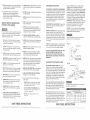
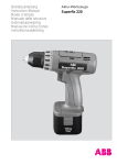
This tool is intended for use on a circuit that has a
receptacle like the one illustrated in FIGURE A.
FIGURE A shows a 3-prong electrical plug and receptacle
that has a grounding conductor, if a properly grounded
receptacle is not available, an adapter (FIGURE B) can
be used to temporarily connect this plug to a 2-contact
ungrounded receptacle. The temporary adapter should
be used only until a properly grounded receptacle can
be installed by a qualified technician. The adapter
(FIGURE B) has a rigid lug extending from it that MUST
be connected to a permanent earth ground, such as a
properly grounded receptacle box. The Canadian
Electrical Code prohibits the use of adapters.
CAUTION: In all cases, make certain the receptacle in
question is properly grounded. If you are not sure have a
certified electrician check the receptacle.
This belt / disc sandejr is for indoor use only. Do not
expose to rain or use in damp locations.
Fig. A
CHECK with a qualified electrician or service personnel if
you do not completely understand the grounding instructions,
or if you are not sure the tool is properly grounded.
3-Prong Plug
USE ONLY 3-W_RE EXTENSION CORDS THAT HAVE
3-PRONG GROUNDING PLUGS AND 3-POLE
RECEPTACLES THAT ACCEPTTHE TOOL'S PLUG,
REPAIR OR REPLACE DAMAGED OR WORN CORD
iMMEDIATELY.
GUIDELINES
FOR
EXTENSION
g Prong
Properly Grounded
3-Prong Receptacle
CORDS
Fig. B
USE PROPER EXTENSION CORD. Make sure your
extension cord is in good condition. When using an
extension cord, be sure to use one heavy enough to carry
the current your product will draw. An undersized cord will
cause a drop in line voltage resulting in loss of power and
overheating. The table below shows the correct size to
use depending on cord length and nameplate ampere
rating. If in doubt, use the next heavier gauge. The smaller
the gauge number, the heavier the cord.
Be sure your extension cord is properly wired and in
good condition. Always replace a damaged extension
cord or have it repaired by a qualified person before
using it. Protect your extension cords from sharp objects,
excessive heat and damp or wet areas.
Use a separate electrical circuit for your tools. This circuit
must not be less than #12 wire and should be protected
with a 15 Amp time tag fuse. Before connecting the motor
to the power line, make sure the switch is in the OFF
position and the electric current is rated the same as the
current stamped on the motor nameplate. Running at a
lower voltage will damage the motor.
SAVE THESE
Grounding Lug
-- Make Sure This
is Connected to a
Known Ground
"" 2-Prong
Receptacle
This tool must be grounded while in use to protect the
operator from electrical shock.
(when using 120 volts only)
Ampere
Rating
i
Total leng!h of cord in feet
more than
notmorethan
25'
50'
100'
150'
0
6
18
16
16
14
6
t0
18
16
14
12
I0
12
16
16
14
12
12
16
14
12
Not recommended
INSTRUCT ONS
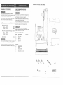
UNPACKING
AVAPLABLE
UNPACKING
CONTENTS
ACCESSORIES
Use only accessories recommended for this belt/disc
sander. Follow instructions that accompany accessories. Use
of improper accessories may cause hazards.
Visit your Sears Hardware Department
or see the Sears
Power and Hand Tool Catalog for the following
accessories:
1TEM
STOCK
Abrasive belts, 2 x 42-in.:
Fine:
120 Grit
Medium:
80 Grit
Coarse:
50 Grit
Abrasive discs, pressure sensitive, package:
Fine:
120 Grit
Medium:
80 Grit
Coarse:
50 Grit
o
Abrasive cleaner
NUMBER
28480
28481
28482
28318
AND CHECKING
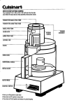
Carefully unpack the belt/disc sander and all its parts, an
compare against the illustration below.
To protect the belt/disc sander from moisture, a protectiw
coating has been applied to the machined surfaces.
Remove this coating with a soft cloth and WD-40.
B
To avoid fire or toxic reaction, never use gasoline,
naphtha, acetone, lacquer thinner or similar highly volatii_
solvents to clean the belt / disc sander•
ITEM
Use only accessories designed for this belt disc sander to
avoid injury from thrown broken parts or workpieces.
SANDER
To avoid injury, if any part is missing or damaged, do not
plug the belt/disc sander in until the missing or damaged
part is replaced, and assembly is complete.
TABLE
22744
YOUR BELT!DiSC
OF LOOSE
PARTS
DESCRIPTION
A.
B.
C.
Disc sander
Belt table
Disc table
D.
E,
Miter gauge
Dust chute
QUANTITY
D
1
1
1
1
1
/
Do not use any accessory unless you have completely
read the instruction
or owner's manual for that accessory•
Loose parts:
G.
Handle assembly
H.
Phillips screws
I.
Washers
J.
Tension handle
K.
Nut
L.
Hex key 3ram, 4mm, 6mm
©
3
6
3
1
1
3
E
C
@
G
J
K
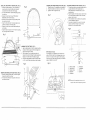
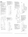
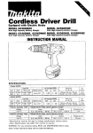
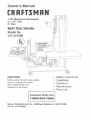
ASSEMBLY
NSTRUCTmONS
Fig. A
Rotation arrow
Belt tracking bolt
For your own safety, never connect plug to power source
outlet until al! assembly and adjustment steps are
completed, and you have read and understood the safety
and operating
instructions,
Disc guard
g belt
Nameplate
Phillips screwdriver
Combination square
Rotation arrow
Hex keys 10ram (3, 4, and 6 mm included)
Belt backstop
Miter
gauge
This belt / disc sander requires minimal assembly.
Tilt index
Belt guard
Belt table
Disc table
locking handle
Mounting hole
Belt guard
knob
Base
Belt housing
Motor
Disc guarlng
d
disc
Dust chute
Disc table
_o
.__
_
"--'------
--_-_--"-_
_
- Titt index
Disc table locking handle
Dust chute
When replacing abrasive disc or abrasive belt, or any parts
on the sander, turn switch OFF and remove the
plug from the power source.
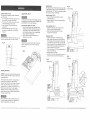
INSTALLING BELTTABLE
t
INSTALLING 1 REPLACING 2" X 42" BELT (FIG, A)
1. Tilt the table (1) out of the way.
2. Remove the belt guard (2) by removing the two belt
guard knobs (3).
3. Release the belt tension by SLIGHTLY moving and
holding the tension handle (4) down.
4. Remove the abrasive belt (5),
5. Install and align the new abrasive belt on the lower
wheel (6), the back wheel (7), and on the top wheel
(8). There is an arrow on the inside of the belt, To avoid
belt damage, this arrow must point in the same
direction as the rotation arrow on the belt housing.
6. Release the belt tension handle (4). Spring action wilt
tension the belt when the handle is released.
7. Make sure the belt is tracking correctly, and adjust if
necessary. When the beft is tracking properly it rides
on the center of each wheel (see "TRACKING THE
BELT"),
8. Replace the belt guard,(2) and the belt table (1).
2,
3.
(FIG. B)
Place the slot (5) of the belt table bracket on to
the lug (6} on the left side of the belt housing.
Place the handle (3) onto the hole (6), Press
buttom (4), screw(7) and tighten.
Be sure the gap between belt and table is 1/I6".
Turn the handle to lock the table.
Fig. B
/_
6
3
7
NOTE: The belt rotates counterclockwise.
When installing a belt, make sure the arrow
points in the same direction
as the rotation arrow on the top of the belt guard
housing, down toward the front bett table.
Power cord
8
9
D
INSTALLING i REPLACING 8" ABRASIVE DmSC (FIG. C)
1. Remove the table assembly (1) from the sander by
loosening and removing the table lock handles (2)
and washers from both sides of the housing.
2. To remove the table, tilt it upward while pulling it away
from the disc.
3. Remove the dust chute (3) (see "INSTALLING /
REMOVING DUST CHUTE" below).
4. Remove the worn abrasive disc (4) by peeling it from
the metal disc plate (5).
5. Clean the metal disc plate if necessary. Apply a new
adhesive sanding disc to the disc plate.
6. Reattach the dust chute and the table assembly and
lock handles.
7. Adjust the table a maximum of 1/16" from the sanding
disc, and tighten the lock handles.
ASSEMBLE THE TENSION HANDLE WITH GRIP (FroG.F)
1. Thread the lock nut (t) completely onto the handle (2).
2. Thread the handle (2) into the hole on the hub (3).
3. Tighten the lock nut against the hub.
Fig. D
Fig. F
1
\
2
°
FASTENING SANDER TO WORK SURFACE (FIG. H)
1. To mount your sander in a permanent location such as
a sturdy workbench, bolt the sander base to a
solid workbench top. The sander base (1) has 4
mounting holes.
2. Place the sander on the work surface, mark the holes
on the work surface and drill 3/8" holes. Use bolts,
washers, nuts to secure.
3. If the workbench moves or shakes during operation,
it must be fastened to the floor.
4. Your sander is designed to be used on hodzoritai
surfaces only. Motor damage may result when
mounted on a non-horizontal surface,
Fig.H
2
Fig. C
4
1
C-I
t
''
ASSEMBLE THE DtSC TABLE {FIG. E)
1. Align the table brackets (1) with the raised track (2) on
the sides of the disc guard. Lift the front edge of the
table and slide onto the tracks.
2.
3.
Place a washer (3) on the table lock handle (4),
thread into the hole (5) through the table bracket slot.
Repeat on the other side of the table and guard.
Be sure the gap between the disc and the disc table
is 1/16" or less. Tighten the handles to lock the table.
MnTER GAUGE (FIG. G)
A miter gauge (1) is supplied with your sander and is
used with the disc table. The miter gauge body can be
turned 0 ° to 45 ° right or left for angle or miter sanding.
Loosen knob (2), rotate miter gauge body to the desired
angle and tighten tock knob (2),
7
t ¸
!
I
1
I
1
I
I
i
t
I
8
9
Fig. G
Fig. E
lM
)
I,
2.
3.
4.
5.
/
REMOVING AND INSTALLING THE DUST CHUTE (FIG. D)
t
Remove or attach the dust chute (1) to the disc guard
housing (2) using the six screws.
2. The dust chute exhaust (3) must point to the side of
the sander as shown.
Belt disc sander
Hex head bolt
Rubber washer
Flatwasher
Workbench
6.
7.
8.
9,
Flatwasher
Lockwasher
Hex nut
Jamb nut
NOTE:Secure tool to supporting structure as toot
may tip, slide,or walk on supporting structure.
0
0
AlwaysturntheswitchOFFandunplugthepowercord
fromthe outletbeforeadjustingyoursander.
ADJUSTMENT
INSTRUCTIONS
TRACKING THE BELT (FIG. 1)
1. With the belt guard removed and the sander plugged
in, flip the switch ON, then OFK
2. The belt should remain centered on the wheels (1) as
they turn.
3. If the belt moves off center, it needs to be adjusted.
4. If the abrasive belt moves to the left, toward the
sander motor, slightly turn the adjusting bolt (2)
clockwise with a hex key. If the belt moves to the right,
away from the sander motor, sJightJy turn the
adjusting bolt counterclockwise.
5. Disconnect the power and test the bett tracking and
table clearances by hand. Adjust if needed.
ADJUSTING THE BELT BACKSTOP (FIG. J)
t. Operating with the backstop (1) in place will allow the
operator to sand or grind straight edges,
2. The backstop should be adjusted so the belt does not
contact it until work is fed into the belt,
3. To adjust the backstop, loosen the bolt (2) with the
hex key, adjust and retighten,
Fig, J
Fig. M
2
Fig. L
©
NOTE: Turn the knob SLIGHTLY to set the proper
tracking,
6.
SQUARmNG THE BELT TABLE (FIG. L )
1. To tilt the table (1) loosen the handle (2).
2. Use a combination square to set the table at
90 °, perpendicular to the sanding belt.
3. Adjust for the 1/16" clearance between the
belt and the table edge.
4. When the belt table is squared to the belt at 90 °,
lock it into position by tightening the handle (2).
5. The table can be tilted for bevel sanding.
6. Loosen handle (2). Lower the table to the desired
angle.
7. Slide the table toward the belt to set a 1/16" gap
between table and belt. Lock handle.
Replace the belt guard when the belt is property
centered and tracking correctly.
ADJUSTING THE DISC TABLE ANGLE (FIG. N}
1. The disc table is adjustable from 0 to 45 ° for
bevel work.
2. To adjust the table, loosen both table lock
handles (1). Adjust the table to the correct angle.
Use the index (2), located on both sides of the
table for an approximate angle.
3. Set the table edge to be 1/16" from the
abrasive disc, tighten the lock handle (1)
to hold the table angle.
2\
REMOVING THE BACKSTOP FOR CONTOUR
SANDING OR POLISHING (FIG. K)
1. Remove the backstop (!) by removing the bolt (2) and
washer (3) from the frame.
2. Replace the backstop assembly when finished.
Fig. K
Fig. N
SQUARING THE DISC TABLE (FIG. M)
To ensure accurate end sanding, the work table (1) must
be square to the sanding surface.
1. Adjust the table (1) to be 90 °, perpendicular to the
sanding disc (2).
2. Using a combination square, check that the table is
90 ° to the sanding disc.
3. If the table is not 90 ° to-the sanding disc, loosen the
table lock handles (3), adjust the table, tighten the
handles and recheck with the square.
J
• •
!
2
"ON/OFF"SWBTCH(FIG.O)
Thekeyedswitchis intendedto preventunauthorized
useof thesander.
1. Toturnthe sanderONinserttheyellowkey(1)into
thekeyslot(2) inthecenteroftheswitch.
2.
3.
4.
Push the key firmty into the slot, then push switch
to the ON position to start the sander.
To turn the sander OFF push the switch to the
down position.
Remove the yellow switch key, when the sander
has come to a complete stop, by gently pulling
it outward.
Remove the switch key whenever the sander is not in use.
Place it in a safe place and out of reach of children.
Fig. O
!
l
'r-
.............
J
............
DISC
(FIG, P)
To avoid injury from slips, jams or thrown pieces, make sure
all adjustments are made. Review section "ASSEMBLY AND
ADJUSTMENTS" for correct disc adjustments.
End sanding and outside curve sanding.
1. Use disc for sanding the ends of small and narrow
workpieces and outside curved edges. Always work on
the right side of the disc center (downward rotation
side), holding the workpiece firmly and applying light
pressure against the sanding disc.
2. The disc moves the fastest and removes more
material at the outer edge.
Using the left side (upward rotation side) of the disc will
cause the workpiece to fly up or kick back and could
result in injury.
ON
I
ABRASIVE
i
2
ABRASIVE BELT
The abrasive belt can be used to sand wood, deburr metal,
or polish plastic and glass, The belt is most efficient when
used with the table. The 1" belt size is convenient for getting
into corners and concave curved edges,
Fig. R
Contour sanding
Straight sanding (FroG,Q)
t. Use to sand wood, remove metal burrs, polish
plastics and glass (1).
2. Keep the backstop (2) in place for straight sanding or
grinding operations,
Contour sanding (FIG. R)
1. Remove the backstop to make the abrasive belt
flexible for contour sanding operations (1),
2. Move the workpiece against the belt to follow
contours of the workpiece (2).
Sharpening
(FIG.S)
1. Adjust the metal table (t) to the desired angle.
2. Make a wooden table-rest that is the same width as
the metal table. Use the belt sander to notch the back
of the table-rest to match the angle of the metal table.
3. Place the table-rest (2) on the metal table, and use the
sander to bevel its front edge until the abrasive belt
comes in contact with its top surface.
4, Position the table-rest !/16" from the abrasive belt and
clamp it to the metal table.
5. Keep the backstop (3) in place.
6. Hold the too! (4) firmly on the table--rest and move toot
gently toward the abrasive belt while sharpening.
Fig, Q
Fig.S
Sharpening
Straight sanding
1
SANDING OPERATIONS
CAUTION: To avoid personal injury andlor damage to the
workpiece,
become familiar with the rotation of the belt and
disc sanding surfaces.
The belt sander rotates clockwise, or downward toward
the table. The disc sander also rotates clockwise,
downward
toward the table on the right side of the disc at
all times. Using the left side of the disc will cause the
workpiece to fly up or kickback and could result in injury.
Review this instruction manual for correct operation,
adjustments,
and basic sanding operations. Apply only
enough pressure to remove material; excessive pressure
wil! reduce sanding efficiency.
After sanding wood and other nommetal materials, clean
the area of sawdust and debris before grinding metal.
Sparks could ignite debris and cause a fire.
3
"'-"
', ":
TROUBLESHOOTMNG
For your safety, turn switch OFF, and remove the power
cord from the electrical outlet before adjusting, cleaning, or
performing maintenance on your sander.
To avoid electric shock or fire, all repairs to the electrical
components should be done by qualified service
technicians.
After sanding wood or non-metallic material, always clean
the sawdust from sander or work area before grinding or
sharpening metal workpieces. Sparks could ignite and
cause a fire.
LUBRICATION
Ball bearings are grease packed at the factory and
require no further lubrication. Use a spray lubricant to
ensure smooth operation on all moving table parts.
Before each use check for damaged, missing, or worn
parts; check for alignment of moving parts, binding,
improper mounting, or any other conditions that may
affect the operation. Should any oFthese conditions exist,
do not use the sander until properly repaired or parts are
replaced. Frequently blow or vacuum dust from alf sander
parts and motor housing.
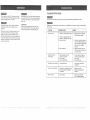
GUIDE
Turn switch OFF and always remove plug from power source before making any adjustments or repairs,
All electrical or mechanical repairs, should be done only by qualified service technicians. Contact the nearest Sears
Service Center.
PROBLEM
PROBABLE
Motor will not run.
1. Defective or broken ON/OFF switch.
CAUSE
REMEDY
1-3, Replace all broken or defective
parts before using sander.
2. Defective or damaged switch cord.
3. Defective or damaged switch relay.
4. Burned out motor,
4.
5. Blown house fuse.
5.
1. Operator applying too much
pressure to workpiece,
2. Dirt on wheels.
3. Worn or stretched belt.
I.
2.
3.
Sanding belt runs off pulleys.
1. Not tracking properly.
1.
Adjust tracking. See section
"TRACKING".
Wood burns while sanding.
,
Sanding disc or belt glazed with sap.
2. Excessive pressure being applied
to workpiece.
I.
2.
Replace belt or disc.
Reduce pressure applied to
workpiece.
Motor overheats.
1. Motor overload.
1.
Reduce
motor
load.
Allow
to
coot off
before
restarting.
Machine stows down
while sanding.
Consult your local Sears Service
Center, Any attempt to repair this
motor may create a hazard unless
repair is done by a qualified
technician.
Replace house fuse. Turn OFF
other appliances and power tools
on the same circuit.
Use less pressure in applying
workpiece to sanding surface.
Clean wheels.
Replace pulley belt.
,,,,,,,,,,,
16': :::::
::::::::: ::::: : : : ::
::: :
:: : :: :
:
:=,i
t7
::: ::::::
:::::::::
:: :: ::::::::::::::::::::::::
::::: ::::::::::::::::::::
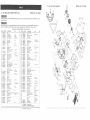
2" × 42"
2" x 42"
BELT/DISC
SANDER
PARTS
When servicing use only CRAFTSMAN
product damage.
LJST
MODEL
BELTiDmSC
[V_ODEL NO. 137,215280
SANDER
NO. I37.215280
replacement parts. Use of any other parts may create a HAZARD or cause
Any attempt to repair or replace electrical parts on this belt / disc sander may create a HAZARD
done by a qualified service technician.
Repair service is available at your nearest Sears Service
unless repair is
Center.
Always order by PART NUMBER, not by key number
Key No.
1
2
3
4
5
Part
3AB00101
STD851037
STD852005
3AB00401
STD522507
No.
Description
Base
Flat washer
Lock washer
Socket head boll
Hex, head boll
Size
Q'ty
Key
STD551031
3AB00701
STD55t025
STD54t025
3AB01001
Fiat washer
Rubber foot
Fiat washer
Hex, nut
Screw
3AB0110I
3AB01201
3AB01401
STD541025
Capacitor
Capacitor
Set screw
Capacitor
Hex, nul
3/8
5ram
M8"30
1t4"'5/8"
5
4
4
4
52
53
54
55
3AB0520t
3AB0530t
3AB0540I
3AB05501
Key
Abrasive
disc
Dust chute
[_eft trunnion
5/!6"
8
4
8
4
!
t
t/4"
1t4"
MI0"12
STD551025
Spring
washer
17
18
19
20
3AB0t70I
3AB01801
3AB01901
3AB02001
Socket head bolt
Strain relief plate
Strain relief
Line cord
2i
22
23
24
25
3AB02t01
3AB02201
3AB02301
3AB02401
3AB02501
Relay
Strain relief hushing
Thread forming screw
Motor housing base
Switch w_th key
disc
Q'ty
8"
t
1
1
1
1
5'5°30mm
8"
asst,
i
3AB05601
3AB05701
3AB05801
3AB05901
STD541025
Set screw
Socket head
Belt housing
Handle
Hex. nut
6-.80"6mm
t0-1.5"20mm
boll
1
2
1
1
1
I/4"
©
...............................................................................................................................
t/4"-20
1
t
6
1
4
t/4"
4
66
3AB06601
Shaft
8_1.25"25mm
4
1
1
I
67
68
69
70
3AB06701
3AB0680I
3AB0690I
3AB0700t
Bearing
tdter wheel
Retaining
ring
Abrasive
belt (medium)
1
t
2
t
1
7"[
72
73
74
75
3AB0710!
3AB0720t
3AB07301
3AB07401
3AB0750!
Stand off
Drive wheel
Set screw
Belt cover
Knob
3t16"3/8
Size
..............................................................................................................................
56
57
58
59
60
61
62
63
64
65
................................................................................................................................
f6
Description
Aluminum
cap
wii washer
ctamp
No,
3AB05t0t
................................................................................................................................
1t
t2
t3
14
15
Part
51
...........................................................................................................................
6
7
8
9
10
No,
1
t
3AB0610
t
STD55103I
3AB0630t
3AB08401
3AB06501
Hex. head bolt
Flat washer
Belt table bracket
Belt tabte
Set screw
8-1.25_t
5/16"
:ram
2
3
1
t
8_i2'12mm
\
................................................................................................................................
©
©
\
t
G202 ZZ
4
2
2
1
Sq5
2*42"
\
/
3/16"3/8
...............................................................................................................................
26
Copper
27
28
29
30
Sel screw wiJ washer
Hex, nut
End shield
Bearing
STD840508
3AB0290t
3AB0300!
t
washer
3/t6"1/4
5mm-,80
3AB03101
3AB0320t
3AB03301
STD5125t0
3AB03501
Molor fan
Armature
SIator
Pan head screw
Motor housing
6203
ZZ
36
37
38
39
40
3AB03601
3AB03701
3AB03801
3AB0390t
3AB04001
Pan head screw
Miter gauge bar
Indicator
C_os,_
head5crew
Protraclor
scale
76
3AB07701
Retaining
2
4
2
2
77
78
79
80
3AB0760t
3AB0780t
3AB0790!
3AB0800t
Tracking whee! cam
Tension spring
Spring cap
Handle with knob
i
!/4"7/8
5-.80"t63mm
4*6ram
STD55t025
3AB04201
3AB0430t
3AB04401
3AB04501
Flat washer
Knob
Miter gauge assembly
Flat head screw
Disc table
{Rel. Nos.37-42,g9,100
6"!5mm
3AB04601
3AB04701
3AB04801
3AB04901
3AB05001
Armature
guard
Handle
Righl trunnion
Disc guard
Nut
1
1
I
I
................................................................................................................................
Tracking
bracket
Hex. nut
Socket head bolt
6tom-1.0
6-1,0"20mm
1
1
1
84
85
3AB08401
3AB08501
Spring
Socket
5-.80"10mm
2
2
4
1
1
1
1
86
87
88
89
90
3AB08601
3AB08701
3AB08801
3AB08901
3AB0900t
Socket head bolt
Belt platen
Socket head bolt
Hex wrench
Hex wrench
5_,80"12mm
2"
8 _1.25 _ 16ram
6mm
4ram
2
I
1
I
1
3mm*140mm
5/16"
3t16"1/4
5mm
#22,#200mm
1
4
2
1
1
A-3
#18.100ram
1/4 x 3i8mm
4mm
1/4"
t
1
1
1
!
1
1
t
4
1
t ......
2
1
1
4
plale
head
boll
................................................................................................................................
91
92
93
94
95
i
M8
S-I7
3AB0810I
STD8406!0
3AB08301
................................................................................................................................
46
47
48
49
50
1
shaft
81
82
83
i
1/4"
rifle
t
1
t
4
1
................................................................................................................................
41
42
43
44
45
................................................................................................................................
i
................................................................................................................................
31
32
33
34
35
6ol .0 ,10mm
2
I
1
t
2
3AB09101
STD55113t
Hex wrench
Lockwasher
Set screw wii washer
Serrated
washer 5mm
Cable
................................................................................................................................
96
97
98
99
100
3AB09801
3AB09901
3AB1000!
Connector
Cable
Set screw
Flat washer
piaslic
washer
:........
t37215280111
...........................................................
1
Nameplate
/ Warning
label
I
18
137215280222
Rotation
label
1
\