1
truction
anu
®
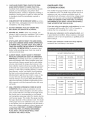
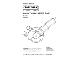
6-1/8-in. Wide
1-1/2 Horsepower (continuous
duty)
5000 Cutterhead R.P.M. (no load speed)
/
Mode_ No.
152.217050
C
S
FOR YOUR OWN SAFETY; Read
and foUlow all of the Safety and
Operating Instructions before
Operating this Table Saw.
Customer Helpline
1-800-897-7709
PRease have your Model No.
and SedaR No. availabUe.
Sears,
Roebuck
Part No. 0R92216
and Co., Hoffman
Estates,
JL 60179 U.S.A.
EspaSoU, pg, 33
SECTION
PAGE
Warranty..............................................................................................................................................................
2
ProductSpecifications
..........................................................................................................................................
2
Safetyinstructions...............................................................................................................................................
3
Groundinginstructions.........................................................................................................................................
5
SpecificSafetyinstructionsfor Jointer/Ptaner.........................................................................................................
6
AccessoriesandAttachments................................................................................................................................
7
CartonContents...................................................................................................................................................
8
KnowYourJointer/PJaner
......................................................................................................................................
10
Assemblyinstructions..........................................................................................................................................
11
Operatingthe JointedPtaner..................................................................................................................................
18
DustCollectionfor the JointedPtaner
.....................................................................................................................
25
Maintenance
........................................................................................................................................................
26
TroubleshootingGuide.........................................................................................................................................
27
PartsList.............................................................................................................................................................
28
EspaSoJ
...............................................................................................................................................................
33
Service information
......................................................................................................................................
Back Cover
ONE FULL YEAR WARRANTY
if this product fails due to a defect in material or workmanship within one year from the date of purchase,
call 1-800-4-MYoHOME C_)
to arrange for free product repair,
This warranty gives you specific legal rights, and you may also have other rights, which vary, from state to state,
Sears, Roebuck and Co,, Dept, 817 WA, Hoffman Estates, IL 60179
Motor
Continuous Duty HP
1-1/2
Volts
120
Hertz
6O
RPM
3450 R,P,M
(no load speed)
Infeed table dimension:
22-inch
Outfeed table dimension:
22-3/8-inch
Fence Tilt:
45 Degrees in and out
Fence Positive Stops:
90, 45 Degrees in and out
Cutterhead RPM:
5000 RPM
To avoid electrical shock to yourself and damage to the
Jointer/Planer, use proper circuit protection,
The Jointer/Planer is factory wired for 120V, 60 Hz,
operation, Connect to a 120V, 15 amp branch circuit
and use a 15 amp time delay fuse or circuit breaker,
The electrical circuit cannot have any wire size less
than #14, To avoid shock or fire, replace power cord
immediately if it is damaged in any way,
GENERAL
SAFETY
INSTRUCTmONS
Operating a Jointer/Haner can be dangerous if safety
and common sense are ignored, The operator must be
familiar with the operation of the tool Read this manuaU
to understand this Jointer/Haner, DO NOT operate this
Jointer/Haner if you do not fully understand the Hmitations of this tool DO NOT modify this Jointer/Haner in
any way,
BEFORE
READ the entire Owner's Manual, LEARN how to
use the tool for its intended applications,
GROUND ALL TOOLS, If the tool is supplied with
a 3-prong plug, it must be plugged into a 3-contact
electrical receptacle, The 3rd prong is used to
ground the tool and provide protection against
accidental electric shock, DO NOT remove the 3rd
prong, See Grounding Instructions,
3,
4,
5,
6,
7,
8,
ALWAYS WEAR EYE PROTECTION, Any power
tooUcan throw debris into the eyes during operations, which couUd cause severe and permanent
eye damage, Everyday eyegUasses are NOT safety
gUasses, ALWAYS wear Safety Goggbs (that
compUy with ANSi standard Z87,1) when operating
power toob, Safety Goggbs are avaHabb at Sears
Retail Stores,
USUNG THE JOINTER/PLANER
To avoid serious injury and damage to the tool, read
and follow all of the Safety and Operating Instructions
before operating the Jointer/Haner,
2,
9,
10, ALWAYS WEAR HEARING PROTECTION,
Plain cotton is not an acceptable protective device,
Hearing equipment should comply with ANSI $3,19
Standards,
11, ALWAYS UNPLUG THE TOOL FROM THE ELECTRICAL RECEPTACLE when making adjustments,
changing parts or performing any maintenance,
12, KEEP PROTECTIVE
GUARDS IN PLACE AND IN
WORKING ORDER,
13, AVOID ACCIDENTAL
STARTING, Make sure that
the power switch is in the "OFF" position before plugo
gins in the power cord to the electrical receptacle,
AVOID A DANGEROUS WORKING ENVIRONMENT. DO NOT use electrical tools in a damp
environment or expose them to rain,
14, REMOVE ALL MAINTENANCE
DO NOT use electrical tools in the presence of
flammable liquids or sasses,
15, USE ONLY RECOMMENDED
ALWAYS keep the work area clean, well lit, and
organized, DO NOT work in an environment with
floor surfaces that are slippery from debris, grease,
or wax,
KEEP VISITORS AND CHILDREN AWAY, DO NOT
permit people to be in the immediate work area,
especially when the electrical tool is operating,
DO NOT FORCE THE TOOL to perform an opera°
tion for which it was not designed, It will do a safer
and higher quality job by only performing operations
for which the tool was intended,
WEAR PROPER CLOTHING. DO NOT wear loose
clothing, gloves, neckties, or jewelry, These items
can get caught in the machine during operations
and pull the operator into the moving parts, Users
must wear a protective cover on their hair, if the
hair is long, to prevent it from contacting any
moving parts,
TOOLS from the
immediate area prior to turning "ON" the Jointed
Planer,
ACCESSORIES,
Use of incorrect or improper accessories could
cause serious injury to the operator and cause
damage to the tool, If in doubt, check the instruction
manual that comes with that particular accessory,
16, NEVER LEAVE A RUNNING TOOL UNATTENDED,
Turn the power switch to the "OFF" position, DO
NOT leave the tool until it has come to a complete
stop,
17, DO NOT STAND ON A TOOL, Serious injury could
result if the tool tips over or you accidentally contact
the tool,
18, DO NOT store anything above or near the tool where
anyone might try to stand on the tool to reach it,
19, MAINTAIN YOUR BALANCE. DO NOT extend your°
self over the tool, Wear oil resistant rubber-soled
shoes, Keep floor clear of debris, grease, and wax,
20, MAINTAIN TOOLS WITH CARE, Always keep tools
clean and in good working order, Keep all blades
and tool bits sharp
SAVE THESE INSTRUCTIONS.
21. EACH AND EVERY TmME,CHECK FOR DAMAGED PARTS PRmORTO USmNGTHE TOOL.
Carefully check aH guards to see that they operate
properUy, are not damaged, and perform their
intended functions. Check for alignment, binding or
breaking of moving parts. A guard or other part that
is damaged shouUd be immediateUy repaired or
repUaced.
22. CHILDPROOF THE WORKSHOP AREA by removing switch keys, unplugging tools from the electrical
receptacles, and using padlocks.
GUIDEUNES
EXTENSUON
FOR
CORDS
The smaller the gauge-number, the larger diameter of
the extension cord, if in doubt of the proper size of an
extension cord, use a shorter and thicker cord, An
undersized cord wiii cause a drop in line voltage resulting in a loss of power and overheating, USE ONLY A
3-WIRE EXTENSION CORD THAT HAS A 3-PRONG
GROUNDING PLUG AND A 3-POLE RECEPTACLE
THAT ACCEPTS THE TOOL'S PLUG.
23, DO NOT OPERATE TOOLS IF UNDER THE
INFLUENCE OF DRUGS OR ALCOHOL.
If you are using an extension cord outdoors, be sure
it is marked with the suffix "W-A" CW" in Canada) to
indicate that it is acceptable for outdoor use.
24. SECURE ALL WORK. When it is possible, use
clamps or jigs to secure the workpiece. This is safer
than attempting to hold the workpiece with your
hands.
Be sure your extension cord is property sized, and
in good electrical condition. Always replace a damaged
extension cord or have it repaired by a qualified person
before using it.
25, STAY ALERT, WATCH WHAT YOU ARE DOING,
AND USE COMMON SENSE WHEN OPERATING
A POWER TOOL. DO NOT USE A TOOL WHILE
TIRED OR UNDER THE INFLUENCE OF DRUGS,
ALCOHOL, OR MEDmCATmON,A moment of inattention while operating power tooUsmay resuUt in
serious personaU injury.
Protect your extension cords from sharp objects,
excessive heat, and damp or wet areas,
120 VOLT OPERATION ONLY
26, ALWAYS WEAR A DUST MASK TO PREVENT
INHALING DANGEROUS DUST OR AIRBORNE
PARTICLES, including wood dust, crystalline sHba
dust and asbestos dust, Direct particles away from
face and body, Always operate tool in well ventilated area and provide for proper dust removal, Use
dust collection system wherever possible, Exposure
to the dust may cause serious and permanent respiratory or other injury, including silicosis (a serious
lung disease), cancer, and death, Avoid breathing
the dust, and avoid prolonged contact with dust,
Allowing dust to get into your mouth or eyes, or lay
on your skin may promote absorption of harmful
material, Always use properly fitting NIOSH/OSHA
approved respiratory protection appropriate for the
dust exposure, and wash exposed areas with soap
and water,
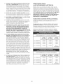
27, USE A PROPER EXTENSION CORD IN GOOD
CONDITION. When using an extension cord, be
sure to use one heavy enough to carry the current
your product will draw, The table to the right shows
the correct size to use depending on cord length
and nameplate amperage rating, if in doubt, use the
next heavier gauge. The smaller the gauge number,
the larger diameter of the extension cord. if in doubt
of the proper size of an extension cord, use a short°
er and thicker cord. An undersized cord will cause a
drop in line voltage resulting in a loss of power and
overheating, USE ONLY A 3_WIRE EXTENSION
CORD THAT HAS A 3-PRONG GROUNDING
PLUG AND A 3-POLE RECEPTACLE THAT
ACCEPTS THE TOOL'S PLUG.
25' LONG
50' LONG
100' LONG
0 to 6 Amps
18 AWG
16 AWG
16 AWG
6 to 10 Amps
18 AWG
16 AWG
14 AWG
12 Amps
16 AWG
16 AWG
14 AWG
12 to 15 Amps
14 AWG
12 AWG
10to
Not
recommended
240 VOLT OPERATION ONLY
25' LONG
50' LONG
100' LONG
0 to 6 Amps
18 AWG
18 AWG
16 AWG
6 to 10 Amps
18 AWG
18 AWG
14 AWG
12 Amps
16 AWG
16 AWG
14 AWG
12 to 15 Amps
14 AWG
12 AWG
10to
Not
recommended
THiS TOOL MUST BE GROUNDED WHILE iN USE
TO PROTECT THE OPERATOR FROM ELECTRIC
SHOCK.
iN THE EVENT OF A MALFUNCTION OR BREAKDOWN, grounding provides the path of bast resistance
for eUectric current and reduces the risk of eUectric
shock, This tooUis equipped with an eUectric cord that
has an equipment-grounding conductor and a grounding pDg, The pUugMUST be pDgged into a matching
eUectrbaUreceptacle that is properUy installed and
grounded in accordance with ALL bcaU codes and ordinances,
DO NOT MODIFY THE PLUG PROVIDED. ff it wHUnot
fit the eUectrbaUreceptacb, have the proper eUectrbaU
receptacle installed by a qualified electrician,
IMPROPER ELECTRICAL CONNECTION of the equipment-grounding conductor can result in risk of electric
shock, The conductor with the green insulation (with or
without yellow stripes) is the equipment-grounding
conductor, DO NOT connect the equipment-grounding
conductor to a live terminal if repair or replacement of
the electric cord or plug is necessary,
CHECK with a qualified electrician or service personnel
if you do not completely understand the grounding
instructions, or if you are not sure the tool is properly
grounded,
The motor supplied with your Jointer/Planer is a dual
voltage 120/240 volts, 60 hertz alternating current,
single phase motor, it is shipped wired for 120 volts
application, Never connect the green or ground wire to
a live terminal,
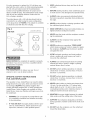
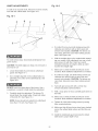
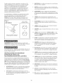
Fig. 1A
120 Volt
USE ONLY A 3-WIRE EXTENSION CORD THAT HAS
A 3-PRONG GROUNDING PLUG AND A 3-POLE
RECEPTACLE THAT ACCEPTS THE TOOL'S PLUG.
REPLACE A DAMAGED OR WORN CORD IMMEDiATELY.
FOR GROUNDED, CORD-CONNECTED MACHINES
INTENDED FOR USE ON A SUPPLY CIRCUIT HAVING
A NOMINAL RATING LESS THAN 150 VOLTS.
This tool is intended for use on a circuit that has an
electrical receptacle as shown in FIGURE 1A. FIGURE
1A shows a 3-wire electrical plug and electrical receptacle that has a grounding conductor, if a properly
grounded electrical receptacle is not available, an
adapter as shown in FIGURE 1B can be used to temporarily connect this plug to a 2-contact ungrounded
receptacle, The adapter has a rigid lug extending from it
that MUST be connected to a permanent earth ground,
such as a properly grounded receptacle box, THIS
ADAPTER IS PROHIBITED IN CANADA.
CAUTION: in all cases, make certain the electrical
receptacle in question is properly grounded, if you are
not sure, have a certified electrician check the electrical
receptacle,
The motor supplied with your Jointer/Planer is a dual
voltage, 120/240 volt, single phase motor, if it is desired
to operate your jointer/planer at 240 volts, it is necessary to reconnect the motor leads in the motor junction
box by following the wiring diagram on the junction box
cover,
MAKE CERTAIN the motor is disconnected from power
source before reconnecting motor leads,
Fig. 1 B
3-prong
electrical
120 Voff
grounding
adapter lug
receptacle
grounding
conductor
3-wire electrical cord
grounding
conductor
3-wire electrical cord
0
2-prong
electrical
receptacle
it is aUsonecessary to repUace the 120 voUtpUug,supplied with the motor, with a UL/CSA Listed pUugsuitabb
for 240 voUts and rated current of the jointer/pUaner,
Contact a bcaU qualified eUectdcian for proper procedures to install the pUug,The jointer/pUaner must compUy
with aH bcaU and nationaU eUectdcaUcodes after the
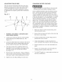
3,
KEEP cutterhead knives sharp and free of all rust
and pitch,
4,
BEFORE starting machine, check cutterhead guard
to make sure it is not damaged and operates freely,
240 voUtpUugis installed,
5,
ALWAYS make sure exposed cutterhead behind
the fence is guarded, especially when jointing near
the edge,
6,
NEVER perform jointing or planing operations with
the cutterhead guard removed,
The jointer/planer with a 240 volt plug should only be
connected to an outlet having the same configuration
as the plug shown in FmGURE 2, No adapter is available
or should be used with the 240 volt plug,
Fig. 2
7,
grounded outlet box
240 Volt
current carMng
prongs
6)
grounding blade is
longest of the 3 blades
MAKE CERTAIN the infeed and outfeed tables are
tightened before starting the machine,
8,
NEVER start the jointer with the workpiece contacting the cutterhead,
9,
ALWAYS hold the workpiece firmly against the
tables and fence,
10, NEVER perform any operations "FREE-HAND"
which means using your hands to support or guide
the workpiece, ALWAYS use the fence to position
and guide the work,
11, AVOID awkward operations and hand positions
where a sudden slip could cause your hand to
move into the cutterhead,
MAKE CERTAIN the receptacle in question is properly
grounded, if you are not sure have a qualified electrician check the receptacle,
12, ALWAYS use hold-down/push blocks for jointing
material less than 3 inches in height or planing
material thinner than 3 inches,
This Jointer/Planer is for indoor use only, Do not
expose to rain or use in damp locations,
13, DO NOT perform jointing operations on material
shorter than 10 inches, narrower than 3/4 inch or
less than 1/2 inch thick,
SPECIFIC SAFETY iNSTRUCTiONS
FOR JOINTER/PLANER
14, DO NOT perform planing operations on material
shorter than 10 inches, narrower than 3/4 inch or
less than 1/2 inch thick,
The operation of any Jointer/Planer can result in debris
being thrown into your eyes, which can result in severe
eye damage, ALWAYS wear Safety Goggles (that
comply with ANSi standard Z87,1 ) when operating the
Jointer/Planer, Safety Goggles are available at Sears
Retail Stores, Keep your thumbs and fingers away from
the cutterhead,
15, NEVER make jointing or planing cuts deeper than
1/8 inch, On cuts more than 1-1/2 inches wide,
adjust depth of cut to 1/16 inch or less to avoid
overloading machine and to minimize chance of
kickback (work thrown back toward you),
1,
2,
WARNING: Do not operate the Jointer/Planer until
it is completely assembled and installed according
to the instructions,
IF YOU ARE NOT thoroughly familiar with the operation of Jointers/Pianers, obtain advice from your
supervisor, instructor or other qualified person,
16, MAINTAIN the proper height between the outfeed
table surface and the cutting circle of the knives,
17, SUPPORT the workpiece adequately at all times
during operation; maintain control of the work at all
times,
18, DO NOT back the workpiece over the cutterhead
toward the infeed table,
19, DONOTattemptto performanabnormalor littleusedoperation
withoutstudyandtheuseofadequateholddown/push
blocks,jigs,fixtures,stops,
pushblocks,etc,
20, SHUTOFFpowerbeforeadjustingjointer,
21, DISCONNECT
Jointer/Haner
frompowersource
beforeservicinganddean themachinebefore
havingit,
22, MAKESUREtheworkareais cleanbeforehaving
themachine,
23, SHOULDanypartofyourjointerbemissing,damaged,or failinanyway,or anyebctdcalcomponentsfailto performproperly,shutoffswitchand
removeplugfrompowersupplyoutbt,Replace
missing,damaged
or faibdpartsbeforeresuming
operation,
24. THEUSEofattachments
andaccessories
not
recommended
mayresultin the riskofinjuries.
25, USEofthistoolcangenerateanddisbursedustor
otherairborneparticles,includingwooddust,crystallinesilicadustandasbestosdust,Directparticles
awayfromfaceandbody,Alwaysoperatetoolin
wellventilatedareaandprovideforproperdust
removal,Usedustcollectionsystemwhereverpossibb, Exposuretothedustmaycauseseriousand
AVAILABLE
ACCESSORIES
Visit your Sears Hardware Department or see the
Sears Power and Hand Tool Catalog for the following
accessories.
ITEM
permanent
respiratory
or otherinjury,including
silicosis(a seriouslungdisease),cancer,and
death.Avoidbreathingthedust,andavoidprolongedcontactwithdust.Allowingdustto getinto
yourmouthor eyes,or layonyourskinmaypromoteabsorption
ofharmfulmaterial.Alwaysuse
properlyfittingNIOSH/OSHA
approvedrespiratory
protectionappropriate
forthedustexposure,and
washexposedareawithsoapandwater.
26. ADDITIONAL
INFORMATION
regardingthesafe
andproperoperation
of thisproductis available
from:
PowerToolinstitute
1300SummerAvenue
Cleveland,
OH44115-2851
www.powertoolinstitute.org
NationalSafetyCouncil
1121SpringLakeDrive
Itasca,IL60143-3201
AmericanNationalStandardsinstitute
25West43rdStreet,4th Floor
NewYork,NY10036
www.ansi.org
ANSi01.1SafetyRequirements
for
Woodworking
Machines
andthe
U.S.Department
of LaborRegulations
www.osha.gov
27, SAVETHESEINSTRUCTIONS,
Referto them
oftenandusethemto instructothers,
Sears may recommend other accessories not listed in
this manual.
See your nearest Sears Hardware Department or Sears
Power and Hand Tool Catalog for other accessories.
Do not use any accessory unless you have completely
read the Owner's Manual for that accessory.
Replacement Push Blocks
Use only accessories recommended by Sears for this
Jointer/Planer. Using other accessories may cause
serious injury and cause damage to the Jointer/Planer.
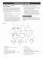
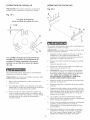
UNPACKUNG
AND CHECKUNG CONTENTS
The Jointer/Haner is a heavy machine, two peopb are
required to unpack and lift it, This machine will require
some amount of assembly, You will need for assembly
a #2 Phillips screwdriver, 8mm, lOmm, 14mm, 16mm,
17mm and 19mm open end wrench (not included), Hex
wrenches 2,5mm, 3mm, 4mm and 6mm are provided,
1,
Remove all parts from the carton and lay them on a
clean work surface,
2,
Two or more people are required to lift the
Jointer/Planer out of the carton,
3,
Remove all protective materials and coatings from
the parts, The protective coatings can be removed
by spraying WD-40 on a part and wiping it off with a
soft cloth, This may need to be redone several
times before all of the protective coatings are
removed completely,
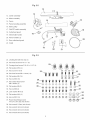
Fig. 2-1
CAUTION: DO NOT use acetone, gasoline or
lacquer thinner to remove any protective coatings,
4,
After cleaning, apply a good quality automotive wax
to any unpainted surfaces, Make sure to buff out
the wax before assembly,
5,
Compare the parts to figures 2-1,2°2, and 2-3,
Verify that all items are accounted for before discarding the shipping carton, if there are any missing
parts, call Customer Helpline 1-800-897°7709,
Please have your part number ready, Part numbers
can be found in the Parts List section of your
instruction Manual,
To avoid injury, DO NOT turn on the Jointer/Planer until
all parts have been assembled correctly, if any parts
are broken or missing DO NOT use until the parts have
been obtained and assembled,
3
2
4
11
10
9
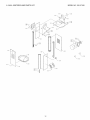
1,
Front panel
Note: This panel has the Craftsman Professional
label,
2,
Back panel
3,
Right side panel assembly
4,
Left side panel assembly
Note: The left side panel assembly has the large
square cut out in it,
5,
Top plate
6,
Bottom plate
7,
Dust chute
8,
Push blocks (2)
9,
Dust chute port
Note: Dust Chute Port is only to be assembled if a
dust collector is to be used with this Jointer/Planer,
10, Cutterhead pulley guard
11, Push block holder
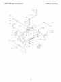
Fig. 2-2
12
12, Jointerassembly
13, Motorassembly
14, Fence
15, Fencebevelingassembly
16, Motorpulley
17, ON/OFFswitchassembly
18, Cutterhead
guard
19, Infeedtablehandle
18
17
20, Fencehandles(2)
21, Rearcutterhead
guard
22, V-Belt
22
20
21
Fig. 2-3
23, Leveling feet with hex nut (4)
24, Hex head screw 3/8-16 x 1" (4)
25, Carriage head screw 5/16o18 x 1ol/8" (4)
26, Fiat washer MIO (4)
27, Hex nut 5/16°18 (4)
28, Hex head screw M6 x 12mm (16)
@@@
@@@
29, Fiat washer M6 (16)
30, Hex nut M6 (16)
31, Hex socket head screw
M8 x 30mm (2)
29----m@ @ @@@@
32, Fiat washer M8 (2)
@@@@
@ @
@
@
(_
32
33, Hex nut M8 (2)
34, Lock washer MIO (3)
35, Fiat washer MIO (3)
©
36, Hex nut MIO (3)
@®
37, Round head flange screw
#10o24 x 3/8" (35) (not shown)
38, Hex wrench 2,Smm (not shown)
39, Hex wrench 3mm (not shown)
40, Hex wrench 4mm (not shown)
41, Hex wrench 6mm (not shown)
©
@@@@
@@@@
@@
36
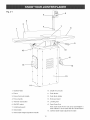
Fig. 3-1
_6
5_
3
2
7
10
12
13
1, Outfeed TaMe
10, Depth-of-Cut scaHe
2, Fence
11, Push Mocks
3, Fence Cam HockhandHe
12, Push Mock hoHder
4, Fence handHe
13, EncHosed stand
5, ThermaH reset button
14, Leveling feet
6, ON/OFF switch
15, Dust Chute Port
Note: Dust Chute Port is onHy to be assembHed if a
dust coHHectoris to be used with this Jointer/PHaner
7, Cutterhead guard
8, Hnfeed tame
16, Outfeed tame height adjustment handHe
9, Hnfeed tame height adjustment handHe
10
Fig. 4-2
I
TO AVOmD SERmOUS mNJURY AND DAMAGE TO THE
JOmNTER/PLANEFt:
1,
DO NOT assemble the Jointer/Planer
sure the tool mSNOT plugged in,
until you are
2,
DO NOT assemble the Jointer/Planer until you are
sure the power switch is in the "OFF" position,
3,
DO NOT assemble the Jointer/Planer until you have
read and understood this entire instruction Manual,
4,
DO NOT assemble Jointer/Planer
missing or damaged,
if any parts are
C
C
G
13"
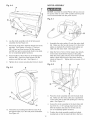
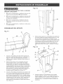
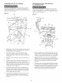
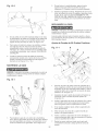
4,
A
Assemble the top plate (J) to the stand assembly
(G) with four 3/8-16 x 1" hex head screws (R), Do
not completely tighten hardware, Note: Make sure
the top plate is positioned with single mounting hob
(K) to the left side panel assembly (A) and the two
mounting hobs (L) to the right side panel assembly
(H) as shown in Figure 4-3,
N
B
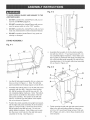
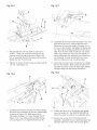
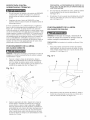
1,
Lay the left side panel assembly (A) on a clean surface as shown in Figure 4-1, Note: The left side
panel assembly has the large square cut out (B) in it,
2,
Assemble the bottom plate (C) to the left side panel
assembly with four M6 x 12mm hex head screws
(D), M6 fiat washers (E) and M6 hex nuts (F), Do
not completely tighten hardware, Note: The bottom
plate must be assembled to the bottom of the left
side panel assembly, The bottom of the left side
panel is 13-inches from the bottom of the square
cut out as shown in Figure 4-1,
3,
Position the stand assembly (G) upright and assemble the right side panel assembly (H) to the bottom
plate (C) using four M6 x 12mm hex head screws,
M6 fiat washers and M6 hex nuts, Do not completely tighten hardware, Note: Make sure to position the power cord hob (I) in the right side panel
assembly to the top, See Figure 4-2,
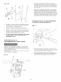
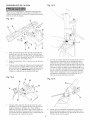
5,
11
Finish securing the left and right side panel assembibs to the top and bottom plates by using four
#10-24 x 3/8" round head flange screws, Call outs
(P) in Figure 4-3 and 4-4 show these locations that
need secured,
Fig. 4-4
MOTOR ASSEMBLY
P
DO NOT assemMe the Jointer/Haner until you are sure
the power switch is in the "OFF" position and the power
cord is disconnected from the power source,
N
A
6,
7,
Lay the stand assemMy onto its Ueftside paneU
assemMy (A) See Figure 4-4,
Hace dust chute (M) in between flanges (N) of the
top pUate, See Figures 4-3 and 4-4, Use four
M6 x 12mm hex head screws, M6 fiat washers
and M6 hex nuts to secure dust chute to top pUate,
Do not compUeteUytighten hardware,
8,
Secure bottom of dust chute (0) to Ueftside paneU
with two M6 x 12mm hex head screws, M6 fiat
washers and M6 hex nuts, See Figure 4-4,
9,
Tighten aft six screws securing dust chute to stand,
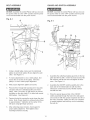
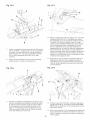
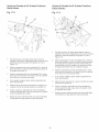
1,
Assemble the motor pulley (A) onto the motor shaft
(B), Make sure the two set screws (C) in the motor
pulley are backed off so that the motor pulley can
slide onto the motor shaft, See Figure 5-1,
2,
AHgn the 5mm x 5mm x 30mm square key aUready
in the motor shaft with the keyway in the pufley,
SHde the motor pufley onto the motor shaft until the
pufley is flush with the end of the motor shaft as
shown in Figure 5-1, Tighten both set screws (C) at
this time,
Fig. 5-2
Fig. 4-5
C
D
p
X\
H
E
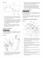
10, Thread the four leveling feet with hex nuts (P) to
the tapped holes (Q) in the side panel assemblies,
See Figure 4-5,
12
3,
Place the motor assembly (D) onto the dust chute
(E), Make sure the motor pulley (C) is positioned
on the same side as the belt opening (F) in the top
plate, See Figure 5-2,
4,
Secure the motor assembly to the dust chute with
four 5/16-18 x 1-1/8" carriage head screws (G),
MIO flat washers (H) and 5/16-18 hex nuts (I),
Do not completely tighten hardware,
5,
Position the stand assembly upright and adjust
leveling feet so that the stand sits flat to the floor,
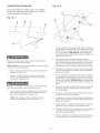
Fig. 5-3
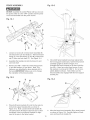
Position the Jointer/Haner (A) onto the stand (B) so
that the three studs under the jointer's base a(ign
with the three sbts in the top plate of the stand,
See Figure 6-1,
1,
K
L
Secure the jointer to the stand with three MIO fiat
washers, MIO bck washers and MIO hex nuts,
Note: Two of the studs in the jointer base can be
accessed inside of the stand, The third stud can
2,
only be accessed through the dust chute opening in
the side panel Securely tighten aU hardware,
(NFEED TABLE
6,
Start two #10-24 x 3/8" round head flange screws
(J) into the right side panel Only screw them in haft
way,
7,
SHde sbts (K) of the push Mock holder (L) down
onto the two screws (J) in the side panel
8,
Attach the arm (M) of the push Mock holder to the
hob (N) in the side pane( with one 10-24 x 3/8"
round head flange screw,
9,
Securely tighten a)( stand hardware except for
motor mounting hardware at this time.
HANDLE
ASSEMBLY
Fig. 7-1
@
JO(NTER/PLANER
C
ASSEMBLY
B
÷
©
DO NOT assemble the Jointer/Haner until you are sure
the power switch is in the "OFF" position and the power
cord is disconnected from the power source,
1,
Assemble infeed table handle (A) with hex nut (B)
into threaded block (C) underneath the infeed table,
See Figure 7-1,
2,
When infeed table handle is completely turned into
threaded block, tighten hex (B) nut against block (C),
CAUTION: Two or more people are required to lift the
Jointer/Haner,
Fig. 6-1
A
13
BELT ASSEMBLY
GUARD
DO NOT assembb the Jointer/Haner until you are sure
the power switch is in the "OFF" position and the power
cord is disconnected from the power source,
DO NOT assembb the Jointer/Haner until you are sure
the power switch is in the "OFF" position and the power
cord is disconnected from the power source,
Fig. 8-1
A
AND SWITCH
ASSEMBLY
Fig. 9-1
O
D
B
A
G
Using a straight edge, make sure the cutterhead
pulby (A) and motor pulby (B) are aligned to each
other, See Figure 8-1,
2,
8,
4,
1,
Assemble the cutterhead pulley guard (A) to the top
plate (B) with two M6 x 12mm hex head screws, M6
fiat washers and M6 hex nuts and tighten all hard°
ware, See Figure 9-1,
2,
Assemble the ON/OFF switch assembly (C) to the
back side of the infeed table (D) with two M8 x
30mm hex socket head screws, M8 fiat washers
and M8 hex nuts,
8,
Place the special plug end (E) of the ON/OFF
switch assembly through the hob in the side panel
and connect it with the special receptacle end (F) of
the motor assembly, Make sure they are completely seated together and that they are not contacting
the belt (G),
To make adjustments to one or both pulbys, first
loosen the set screws in the pulby, Move the
pulby in or out to make proper alignment,
After proper alignment, tighten set screws,
Hace belt (C) through belt opening (D) in top plate
and place belt over cutterhead pulby and motor
pulby, Note: The motor (E) will need to be moved
up higher on the dust chute (F) to allow belt around
both pulleys, See Figure 8-1,
8,
Tension the belt by moving the motor down the dust
chute, Note: Proper tension is achieved when there
is approximately 1" deflection at the center of the
belt span using light finger pressure,
6,
After achieving proper tension, check again for
proper pulley alignment, Then tighten motor
mounting hardware securely,
14
FENCE
ASSEMBLY
DO NOT assemble the Jointer/Haner until you are sure
the power switch is in the "OFF" position and the power
cord is disconnected from the power source,
Fig. 10-1
\
K
J
G
H
B
F
E
C
G
Loosen set screw (A) on fence bevel assembly (B)
and remove the cam lock shaft (C), Remove the bolt
damp (D), M12 fiat washer (E) and M12 Nylock hex
nut (F) from cam lock shaft (C), See Figure 10-1,
5,
2,
Assemble the handles (G) into the fence (H) and
cam lock shaft,
3,
Remove four M8 x 14mm hex socket head screws
(I) and fiat washers (J) from fence, Note: This
hardware was attaching the fence brackets (K) to
the fence,IMPORTANT: Make sure not to change
the orientation of the fence brackets,
Once both fence brackets have been placed onto
the front support bracket pins, hold the fence bevel
assembly upright as shown in Figure 10-3,
Assemble the fence brackets to the fence with the
four M8 x 14mm hex socket head screws (I) and
fiat washers (J) removed in STEP 3, Do not completely tighten hardware, Note: Make sure the
fence brackets stay engaged with the front support
bracket pins,
Fig. 10-2
Fig. 10-4
K
N
N
4,
Hace both fence brackets (K) onto the four pins (L)
in the front support brackets (M), as shown in
Figure 10-2, Note: Loosen bevel lock handle (N)
and pull back the 90-degree stop knob (0) to allow
movement of the front support brackets for alignment of the pins to the fence bracket,
6,
15
Allow the fence bevel assembly (B) to rotate forward
as shown in Figure 10-4, Securely tighten all hardware and bevel lock handle (N),
Fig. 10-5
Fig. 10-7
E
7,
5,
10, Assemble the M12 fiat washer (E) Figure 10-7, and
M12 Nylock hex nut (F) onto the bolt clamp (D),
Make sure the cam lock handle (S) Figure 10-6, is
at a one o'clock position and tighten the Nyloek hex
nut, This sets the locking mechanism for the fence
slide, Now the fence slide should lock and unlock
Reassembb the cam lock shaft (C) removed in
STEP 1, Make sure to place the bolt clamp (D)
onto the cam lock shaft as shown in Figure 10-5,
Do not assembb the M12 fiat washer (E) and M12
Nylock hex nut (F) at this time,
within one quarter turn of the cam lock handle, To
make locking with less movement, turn Nylock hex
nut clockwise, To make locking with more movement, turn Nylock hex nut counterclockwise,
11, Check that the fence locks and unlocks by rotating
the cam lock handle, Make certain that the fence
Tighten set screw (A) until it stops and then back off
1/2 turn, See Figure 10-1,
assembly can move across the table width without
excessive drag from the locking mechanism,
Fig. 10-8
Fig. 10-6
H
I
T
S
9,
Carefully lay the fence assembly (V) which includes
the fence bevel assembly (B) onto the outfeed table
as shown in Figure 10-6, Make sure that the
bolt clamp (D) Figure 10-7, goes through slot (P)
Figure 10-5, in the outfeed table and that the keyway (Q) Figure 10-5, is aligned with the key (R),
12, Position the fence (H) to 90-degrees and tighten
cam lock handle (S). See FENCE OPERATION
section for proper procedures for positioning fence,
13, Remove two screws (T) from the fence bevel
assembly, Assemble the rear cutterhead guard (U)
using the same two screws and securely tighten,
16
CUTTERHEAD
GUARD
ASSEMBLY
FRONT AND BACK
PANEL ASSEMBLY
DO NOT assembie the Jointer/Pianer until you are sure
the power switch is in the "OFF" position and the power
cord is disconnected from the power source,
DO NOT assembie the Jointer/Pianer until you are sure
the power switch is in the "OFF" position and the power
cord is disconnected from the power source,
Fig. 11-1
Assembie the front (A) and back paneis to the jointer
stand with twenty four #10-24 x 3/8" round head flange
screws and secureiy tighten screws, See Figure 12-1,
B
DUST CHUTE
PORT ASSEMBLY
DO NOT assembie the Jointer/Pianer until you are sure
the power switch is in the "OFF" position and the power
cord is disconnected from the power source,
C
Fig. 12-1
A
1,
Remove the screw from the post (A) of the cutterhead guard (B), See Figure 11-1,
2,
Attach the cutterhead guard to the infeed tame (C)
by piacing the post (A) through the hob in the
infeed tame,
3,
Turn knob (D) on underside of the hob 1/2 turn to
provide tension on the return spring, This spring
allows the guard to return over the cutterhead after
the cut has been made,
4,
Align the slot in the post with the spring, then insert
post,
5,
Check that the guard returns completely, if it does
not, remove the guard and add another 1/2 turn to
knob (D), Then replace the guard, using STEP 4
above,
6,
B
if a dust collector (not included) wiii be used with the
Jointer/Planer, attach the dust chute port (B) over the
dust chute opening located on the left side panel, Use
four #10-24 x 3/8" round head flange screws to securely
fasten port to the panel, See Figure 12-1,
Thread screw removed in STEP 1 into cutterhead
guard post, This screw keeps the guard in place,
IMPORTANT: DO NOT assemble the dust chute port if
a dust collector wiii not be used, This wiii only cause
wood chips to backup in the dust chute and come back
out through the cutterhead opening,
17
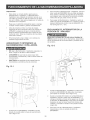
CAUTION
• AseparateeUectdcaU
circuitshouUd
be usedforyour
Jointer/Haner.
TheJointer/Haner
comespre-wired
for
120-voUt
use.ThecircuitshouUd
notbe Uess
than#14
AWGwireandshouUd
be protected
witha 15-amp
timeUag
fuse.
Havea quaUified
eUectdcian
repairor repUace
damagedor worncordimmediateUy.
Beforeconnecting
themotorto thepowerHne,make
certaintheswitchis in the"OFF"positionandbesure
thattheeUectric
currentis ofthesamecharacteristics
asthe motornamepUate.
AHHneconnections
shouUd
makegoodcontact.
Runningon Uow
voUtage
or Uong
extension
cordswHU
damagethemotor.
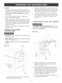
STARTING
2.
To turn the Jointer/Haner on, press the green "ON"
button (B) in one-half inch. Note: There is a safety
feature on the switch to insure that the switch must
be completely pressed before the motor will start.
3.
To turn the Jointer/Haner off, press the large red
"OFF" paddle (C) or lift the paddle and press direct°
ly on the red "OFF" button (D). See Figure 13-1
and 13-2.
LOCKING
SWITCH
IN THE "OFF"
PosmoN
CHILDPROOF THE WORKSHOP AREA by removing
switch keys, unplugging tools from the electrical receptacles, and using padlocks.
AND STOPPING
Fig. 13-2
,, DO NOT expose the Jointer/Haner
it in damp locations,
to rain or operate
MAKE SURE all parts have been assembled correctly
and are in working order,
,, KEEP table surfaces clear of tools and debris before
starting,
Fig. 13-1
A
C
E
B
D
1.
When the Jointer/Planer is not in use, the "ON"
button (B) should be locked so that it cannot be
started. See Figure 13o2.
2.
Using the padlock (E) included with your Jointeri
Planer, lift the red "OFF" paddle (C) and place the
padlock through the holes in the side of the "ON"
button and then lock the padlock. Make sure keys
have been removed from padlock and placed
where no children can get them.
3.
To use the Jointer/Planer, unlock and remove the
padlock from the "ON" button.
r
C
1.
The ON/OFF switch (A) is located on the post over
the infeed table. See Figure 13-1.
18
THERMAL°OVERLOAD
PROTECTION
CAUTION: 1/2" DEPTH-OF-CUT iS ONLY USED
iN RABBET-CUTTING OPERATIONS.
Turn the power switch OFF and unplug the power
cord from its power source prior to performing any
maintenance or adjustments,
3,
After the depth-of-cut is set, tighten the infeed table
lock handle (A), See Figure 14=1,
4,
The pointer (C) on the depth-of-cut scab (D)
indicates the infeed table depth-of-cut, See
Figure 14=1,
Make certain that the OFF button has been depressed
before pushing the thermal-overload-reset button,
The motor supplied with your Jointer/Planer has a
resettable thermal=overload relay (F), see figure 13-1,
if the motor shuts off during an operation (cutting a
workpiece too fast or using a dull blades, using the
jointer beyond its capacity, or low voltage) press the
OFF paddle (C) let the motor cool three to five minutes,
Push the reset thermal-overload button on the side of
the ON/OFF switch, Make certain that the work area
has been cleared of debris before restarting motor, The
motor can now be turned on again by pressing the ON
button (B),
OUTFEED
TABLE
OPERATION
Turn the power switch OFF and unplug the power cord
from its power source prior to performing any maintenance or adjustments,
CAUTION: The knife edges are sharp, Do not touch,
INFEED
TABLE
Turn the power switch OFF and unplug the power cord
from its power source prior to performing any mainte=
nance or adjustments,
1.
in order to perform accurate jointing/planing operations, the outfeed table (A) must be exactly level
with the highpoint (B) of the knives (C), See
Figure 15=1,
1,
OPERATION
Fig. 15-1
E
To raise or lower the infeed table, loosen the infeed
table lock handle (A), To loosen handle, turn
counterclockwise; to tighten, turn handle clockwise,
See Figure 14-1,
A
B
//
Fig. 14-1
7
C
D
3,
2,
Grip the infeed table raise/lower handle, located
under the infeed table and raise or lower handle,
NOTE: For rabbet-cutting operations, the maximum
depth=of=cut pin (B) must be disengaged at 1/8"
depth-of-cut, To disengage, pull knob back toward
you, This will allow the infeed table to lower down
to a maximum of 1/2" depth=of=cut,
19
To adjust the outfeed table (F), loosen lock=thumb
screw (G) on the backside of the outfeed table,
See Figure 15-2,
2,
Standing in front of the jointer, grasp the top of the
fence between the front support brackets (C) and
slide the fence to the desired position,
3,
Tighten cam handle, Make sure the cutterhead
guard (D) returns and rests against the fence,
If not see CUTTERHEAD GUARD ASSEMBLY
section in assembly instruction for setup procedure,
TILTING
G
4,
THE FENCE
Turn the power switch OFF and unplug the power cord
from its power source prior to performing any maintenance or adjustments,
H
The fence can tilt up to 45 degrees in or out, The fence
has positive stops at 45 degrees in, 90 degrees and
45 degrees out,
Turn the hand knob (H) that is under the outfeed
tame clockwise to raise tame or counterclockwise to
Uower tame, See Figure 15-2,
5,
6,
90 Degree
To check UeveU
of tame to knives, set a straight edge
(E) on the outfeed tame, extending over center of
the cutterhead (D), See Figure 15-1, To check that
the knives are installed correctly, see KNUFE
ADJUSTMENTS,
Fig. 17-1
Positive
Stop Adjustment
A
B
When the outfeed tame is exactly UeveU
with the
highpoint of the knives, tighten Uockthumbscrew
(G), See Figure 15-1 and 15-2,
MOVING
THE FENCE
Turn the power switch OFF and unplug the power cord
from its power source prior to performing any maintenance or adjustments,
Fig. 16-1
A
C
B
7
1,
To set fence 90 degree to the table surface, first
make sure the 90 degree stop knob (A) is pushed
in and is inside of slot (B) of the front support
bracket, See Figure 17-1,
2,
Make sure the 90 degree stop knob is against the
90 degree positive stop screw (C),
3,
Tighten tilt lock handle (D), and use an accurate
square to check that the fence is 90 degrees to the
table surface,
4,
To slide the fence (A) across the width of the jointer,
Uoosen the cam UockhandUe (B), Note this handUe
Uocks and unUocks in one quarter rotation of the
handUe, See Figure 16-1,
2O
if any adjustments are needed, loosen tilt lock
handle,
5,
Loosen stop nut (E) and adjust 90 degree positive
stop screw (C),
6,
Retighten bevel lock handle, and recheck that the
fence is 90 degrees to the table surface,
7,
Repeat steps above until fence is set correctly and
then tighten stop nut,
45 Degree
Out Positive
Stop Adjustment
45 Degree
Fig. 17-2
in Positive
Stop Adjustment
Fig. 17-3
H
A
F
1.
To set fence 45 degree in to the table surface, first
make sure the 90 degree stop knob (A) is pulled
out. See Figure 17o3.
2.
Loosen the bevel lock handle (D) and tilt the fence
forward and against the 45 degree in positive stop
screw (H). Note: This positive stop screw does not
touch the fence on the head side of the screw, but
on the threaded end.
To set fence 45 degree out to the tame surface, first
make sure the 90 degree stop knob (A) is pulled
out. See Figure 17-2.
2,
3,
4,
5,
6,
7,
Tighten bevel lock handle (D), and check that the
fence is 45 degrees to the table surface with an
accurate square.
Loosen the beveU bck handb (D) and tilt the fence
back and against the 45 degree out positive stop
screw (F).
3,
Tighten beveU bck handb (D), and check that the
fence is 45 degrees to the tame surface with an
accurate square.
4,
if any adjustments are needed, loosen tilt lock
handle.
5.
Loosen stop nut (I) and adjust 45 degree positive
stop screw (H).
6.
Retighten bevel lock handle, and recheck that the
fence is 45 degrees to the table surface.
7.
Repeat steps above until fence is set correctly and
then tighten stop nut.
if any adjustments
handb.
are needed, bosen tilt bck
Loosen stop nut (G) shown in Figure 17-1 and
adjust 45 degree positive stop screw (F),
Retighten bevel lock handle, and recheck that the
fence is 45 degrees to the table surface.
Repeat steps above until fence is set correctly and
then tighten stop nut,
21
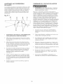
KNIFE ADJUSTMENTS
Fig. 18-2
in order to do accurate work, the knives must be exactly
bveU with the outfeed tame. See Figure 18-1.
H
Fig. 18-1
C
B
/
F
A
/
D
G
E
4,
8,
To avoid serious injury, disconnect jointer/planer from
power source,
CAUTION: The knife edges are sharp. Do not touch or
you may be cut.
6,
1,
Lower infeed table (A) and remove cutterhead
guard, See Figure 18-1,
2.
Set a straight edge (B) on the outfeed table (C),
extending over center of the cutterhead (E). See
Figure 18-1.
7,
8,
DO NOT touch the sharp edge of the knives, Use a
screwdriver or wrench to help rotate the cutterhead,
9,
3.
Carefully rotate the cutterhead. The knives (D)
should touch the straight edge. Check both sides
of the knife (F). See Figure 18-1.
if a knife (D) is low, turn knife locking screws (G)
clockwise one half turn with an 8mm open end
wrench (not included), CAUTION: The knives are
very sharp; take extra care when working around
them, See Figure 18-2,
With the straight edge on the outfeed table extend°
ing over center of the cutterhead, turn one or both
jack screws (H) with the 2.Smm hex wrench
(included) clockwise to bring the knife up until it
touches the straight edge.
Make sure to check the knife at both jack screw
locations. Make additional adjustments as needed.
if a knife (D) is high, turn knife locking screws (G)
clockwise one full turn with an 8mm open end
wrench (not included), CAUTmON: The knives are
very sharp; take extra care when working around
them.
Turn both jack screws (H) with a 2,5mm hex
wrench (included) counterclockwise,
With a scrap piece of wood, carefully push down on
the knife,
10. Make sure to check the knife at both jack screw
locations. Make additional adjustments as needed.
NOTE: Knives should not extend from cutterhead
11. Tighten all of the knife locking screws by turning
them counterclockwise,
more than 1/16 inch. See Figure 19-1.
12. Make sure that all three knives have been checked
across the outfeed table surface and that they are
level,
13. Install the cutterhead guard and raise the infeed
table back to proper depth-of-cut,
22
KNIFE REMOVAL
KNIFE REPLACEMENT
CAUTION: To avoid cutting yourself, be very careful
when removing, replacing and resetting knives,
Fig. 19-1
1/16" of Knife
I_
Protrusion
from
Cutterhead
1/16"
B
B
1
B
A
A
To avoid serious injury, disconnect jointer/planer from
power source.
C
CAUTION: The knife edges are sharp. Do not touch or
you may be cut.
B
Knives (A), Knife-Locking
Bars (B),
and Knife-Locking
Screws (C) must be
assembled
paraHe_ to the face (B) of the
cutterhead
groove.
1.
Make sure the cutterhead (A), knife adjustment
jack screws (C), knife-locking bars (F), and knives
(D) are clean and free of any gum or pitch.
See Figure 20ol.
2.
Replace knife adjustment jack screws into one
cutterhead groove.
3.
Replace knife-locking bar into same cutterhead
groove.
4.
CAUTION: To avoid cutting yourself, take care
when handling knives. The knives are very sharp.
Replace new or re-sharpened knife in cutterhead.
NOTE: SEE FIGURE !9-1 FOR CORRECTLY
INSTALLED POSITION OF KNIFE AND LOCKING
BAR.
To avoid serious injury, disconnect jointer/planer from
power source.
CAUTION: The knife edges are sharp. Do not touch or
you may be cut.
1.
Lower infeed table and remove cutterhead guard.
5.
2.
To relieve stress in the cutterhead, slightly loosen
knife-locking screws in the three knife-locking bars.
Slightly snug knife locking bar screws (E).
See Figure 20ol.
6.
Repeat steps for installing the other two knives.
7.
After the three knives are installed and knife locking
screws are slightly snug, adjust height of knives.
See KNIFE ADJUSTMENTS section for correct
8,
Knives are adjusted properly when the edge of the
knife extends out 1/16" from the cutterhead.
9.
When all knives are properly adjusted, tighten the
knife-locking bar screws, tightening from the inside
to the outside.
3.
Further loosen knife-locking screws in knife-locking
bar and remove knife-locking bar and knife. Repeat
for the other two locking bars and knives.
10. Check that the outfeed table is perfectly level with
the knives at their highpoint, if adjustments are
required, see OUTFEED TABLE OPERATION,
23
ADJUSTING
TABLE
GUBS
CHANGUNG
Gibs are internai mechanisms that take up any piay
between the base and the infeed and outfeed tames.
Precise gib adjustment is done at the factory and
shouid not require any further adjustments. However,
if adjustments are required, phase follow instructions
bebw.
2,
3,
4,
5,
6.
A
A
VOLTAGE
MAKE CERTAIN the Jointer/Haner is disconnected
from the power source before working on motor.
Have a certified electrician make all electrical connections. All local and state codes must be maintained.
The motor supplied with the Jointer/PDner is a dual
voltage 120/240-voit, single phase motor. The motor is
wired from the factory for 120-voit operation. To change
to 240-voit operation for your Jointer/Haner, proceed
with the following instructions. It is also necessary to
replace the 120 volt plug, supplied with the Jointed
Planer, with a UL/CSA Listed plug (not included) suit°
able for 240 volts and the rated current of the motor.
The Jointer/Haner with a 240 volt plug should only be
connected to an outlet having the same configuration
as the plug. No adapter is available or should be used
with the 240 volt plug.
Fig. 21-1
B
MOTOR
C
1,
Make sure switch is OFF and disconnect power
cord from power source,
WARNING: DISCONNECT JOINTER/PLANER
FROM POWER SOURCE.
2,
Remove the front panel and verify on the motor tag
that motor is dual voltage,
Loosen each of the bck nuts (A) on the backside
of the infeed (B) and outfeed tames (C). See
Figure 21-1.
3.
if motor tag states that it is dual voltage remove
junction box cover on motor.
4,
Using wiring diagram on inside of junction box
cover, reconnect motor leads for 240-volt operation,
5,
Replace junction box cover and reassemble front
panel,
6,
Replace 120 volt plug with a UL/CSA Listed 240
volt plug rated for current of the motor,
7.
The ON/OFF switch is a 4-pole switch and does not
need any modifications.
Loosen the infeed tame bck, bcated on the front of
the infeed tame and the outfeed tame thumbqock
screw, bcated on the back of the outfeed tame.
Turn aH set screws (D) in until they bottom out,
fingertight. Do not over-tighten set screws as this
wHi make raising and bwering tames difficuit.
See Figure 21-1.
Recheck piay in the table gibs. If table is difficult to
raise or lower, loosen set screws. If there is still too
much play in gibs, continue tightening set screws.
Tighten lock nuts without letting set screws turn.
24
Useofthistoolcangenerateanddisbursedustor other
airborneparticles,includingwooddust,crystalline
silica
dustandasbestosdust,Directparticlesawayfromface
andbody,Alwaysoperatetoolinwellventilatedarea
andprovideforproperdustremoval,Usedustcollectionsystemwhereverpossible,Exposuretothedust
maycauseseriousandpermanent
respiratory
or other
injury,includingsilicosis(a seriouslungdisease),
cancer,anddeath,Avoidbreathingthedust,andavoid
prolonged
contactwithdust,Allowingdusttoget into
yourmouthor eyes,or layonyourskinmaypromote
absorption
ofharmfulmaterial,
AUways
useproperly
fittingNIOSH/OSHA
approvedrespiratory
protection
appropriate
forthedustexposure,andwashexposed
areaswithsoapandwater,
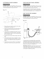
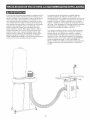
Jointing and planing operations generate large amounts
of wood chips and dust, A dust collection system is recommended for your Jointer/Planer, Provided with your
Jointer/Planer is a dust chute port with a 4" diameter,
A 4" diameter dust collection hose and clamp (not
included) can be connected direct to the Jointer/Planer
for removal of the wood chips and dust,
if you do not have a dust collector a shop vacuum
with a 2-1/2" hose can be used, A reducer kit (not
included) is required to make proper connection from
the 2-1/2" hose to the dust chute port, This Dust
Collection Reducer Kit (4" to 2ol/2"), part number
OR90376 can be ordered through 1-800-4-MY-HOME,
You will have to tell the operator to look under the parts
list of this Jointer/Planer #21705,
Fig. 22-1
25
Repairsto theJointer/Planer
shouldbeperformedby
trainedpersonnel
only,ContactyournearestSears
ServiceCenterforauthorized
service,Unauthorized
repairsor replacement
withnon-factory
partscould
causeseriousinjurytotheoperatoranddamageto the
Jointer/Planer,
tenance to keep your table saw looking new, Cleaning
and waxing the cast iron surfaces on a regular maintenance schedule is recommended as follows:
To ctean and maintain the
unpainted cast iron surfaces:
Apply a heavy coat of WD-40 onto the unpainted cast
iron surface,
Topreventinjurytoyourselfor damageto theJointeri
Planer,turntheswitchtothe "OFF"positionandunplug
thepowercordfromtheelectricalreceptacle
before
makinganyadjustments,
Use a fine steel wool pad to buff the unpainted cast
iron, Make sure to buff in a "front to rear" direction
only, A side4o-side buffing motion will show in the
finely ground cast iron as a flaw, defect or scratches,
TheJointer/Planer
wiiioperatebestif it is keptin proper
operatingcondition,Keepunitadjustedasdescribedin
OPERATING
THEJOINTER/PLANER,
Reapply WD-40 and buff the unpainted cast iron
surfaces until the stains or rust are removed, Make
sure you use the same front-to-rear buffing direction
to avoid scratching or marring the cast iron surface,
Turnthepowerswitch"OFF"andunplugthepower
cordfromitspowersource,
After all stains and/or rust have been removed, clean
all oil and dirt from the table saw using a soft cloth or
rag,
Donotallowgumandpitchtoaccumulate
onthe
tables,fence,knives,andcutterhead
guard,
Donotallowchipstoaccumulate
ontheundersideof
theJointer/Planer,
Lastly, you need to apply a good automotive paste
wax to all unpainted cast iron surfaces, This will help
to protect the saw from rusting from further contact
with moisture or oily hands,
Keepknivessharp,Keepinga sparesetof kniveson
handis recommended,
Knivesshouldalwaysbe
sharpened
or replacedinsetsofthree,Replacement
knivesareavailableat Sears,
LUBRiCATiON
PROTECTING
FROM RUST
CAST
iRON TABLE
The Jointer/Planer has sealed lubricated bearings in
the motor housing and cutterhead that do not require
any additional lubrication from the operator,
Fence guide and elevation screws should be cleaned
of debris and greased as needed,
MAKE CERTAIN to turn the power "OFF" and unplug
the power cord from its power source
Occasionally apply a few drops of light machine oil to
gibs to keep tables free in relation to base,
The environment and frequency of human contact can
have a very detrimental impact on unpainted cast iron
surfaces, Moisture, humidity and oils (from human
hands!) can cause the unpainted cast iron surfaces to
mar or rust, so it is important to conduct routine main-
CAUTION: DO NOT USE FLAMMABLE
MATERIALS
to clean the Jointer/Planer, A clean dry rag or brush is
all that is needed to remove dust and debris buildup,
26
TOPREVENT
iNJURYTOYOURSELF
or damageto theJointer/Haner,
turntheswitchtothe"OFF"positionand
unpUug
thepowercordfromtheeUectdcaU
receptacle
beforemakinganyadjustments,
PROBLEM
UKELY
Motor does not
start
1. Switch not pressed in far enough
switch in the "OFF" position.
2. Defective switch.
3. Defective
Motor stalls
(resulting in bmown
fuses or tripped
circuit breakers)
SOLUTION
CAUSE(S)
or
1: Depress switch in 1/2 inch or make sure switch
"ON" position.
2. Have switch replaced.
motor.
3. Have motor replaced/repaired.
NOTE: 2 and 3 must be done by a qualified
technician.
Consult Sears Service.
4. Low line voltage.
4. Correct
5. Belt tension
5. Adiust belt tension.
too high.
1. Circuit overloaded.
1. Reduce
2. Correct low line voltage
3. Reduce load on motor.
4. Incorrect
fuses on circuit
breakers.
starts
smowly
or fails to come
full speed
to
1. Defective
capacitor.
2. Restricted air circulation
accumulation.
3. Belt tension
Wood
strikes
too high.
Snipe
1. Dull knives.
(gouging
at
end of boards)
depth-of-cut
3. Reduce
Depth-of-cut
does not
match depth-of-scame
90 and 45 degree
cuts inaccurate
Table elevation
adjusts with difficumty
knives.
installed.
circuit load (turn off ether appliances),
2. Inadequate support
3. Uneven feed.
not set correctly.
properly.
4. Friction
PlanMg
between
Outfeed
Knife Height."
2. See "Adjusting Fence"
3. Feed wood slower.
1. Adiust gibs.
2. Clean and lubricate elevation
3. Replace elevation screws.
4. Clean and lubricate.
dirty.
worn.
base and tables.
wood with high moisture.
Remove
1. Too heavy a cut.
2. Knives cutting against
3. Dull knives.
table level. See "Adiusting
1. Adjust fence stops. See 'Tilting the Fence."
2. Clean wood chips from underside of fence.
1. Gibs not adiusted.
screws
screws
and Attachments"
1. Adjust indicator, securely tighten.
2. See 'Adjusting Knife Height."
incorrect.
2. Fence bottom not even with outfeed
table due to wood chips under fence.
2. Elevation
3. Elevation
Table Operation"
knives.
1. Adjust knife height. See "Adjusting
to iointer bed.
1. Fence stops not adiusted
or sharpen
4. Adjust outfeed
1. Knife height not uniform.
1. Indicator
table level, See "Outfeed
2. Support long boards. See "Accessories
3. See "Feeding Workpiece"
of long boards.
table not aligned.
2. Knife projection
Adjust outfeed
1. Replace
2. Fence not perpendicular
3. Feeding wood too fast.
Torn grain
and
air circulation.
1. Reduce load on motor.
2. Have correct fuses or circuit breakers
do not have
Table is above cutterhead
4. Outfeed
grain
insulation
outfeed
Outfeed
Fuzzy
installed.
3. Adiust belt tension.
2. Fuses or circuit breakers
sufficient capacity.
3. Circuit overloaded.
table after passing
over cutterhead
Uneven
1. Reduce load on motor.
2. Clean dust and restore normal
due to dust
1. Motor over!oaded.
Frequent
opening
of fuse or circuit
breakers
fuses on circuit breakers
5. Inspect terminals in motor for damaged
shorted wires and have them replaced.
2. Adiust belt tension.
3. Have capacitor replaced.
1. Motor overloaded.
Motor running
too hot
condition.
1. Have motor replaced/repaired.
2. Drive belt tension too tight.
3. Defective
circuit load (turn off other appliances).
4. Have correct
motor windings.
service
condition.
2. Low line voltage.
3. Motor over!oaded.
5. Short circuit in motor; loose connections
or worn insulation on lead wires.
Motor
line voltage
is in the
high moisture
1. Reduce
grain.
content
depth of cut.
2. Feed work along grain.
3. Replace
27
or sharpen
knives.
screws.
from wood by drying.
Table."
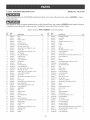
6-1/8qN. JOmNTER/PLANER PARTS UST
When servicing, use only CRAFTSMAN
product damage,
MODEL NO. 152.217050
replacement parts, Use of any other parts may create a HAZARD or cause
Any attempt to repair or replace electrical parts on this Jointer/Planer may create a HAZARD unless repair is done by
a qualified service technician, Repair service is available at your nearest Sears Service Center,
Always order by PART NUMBER, not by key number,
KEY
NO.
PART
NO.
DESCRiPTiON
KEY
NO.
PART
NO.
1
0R90213
BAR
DESCRiPTiON
3
49
0R90257
PLUNGER HOUSING
2
0R90214
KNIFE
1
3
50
0R90258
BALL KNOB
3
0R902!5
KNllEE SCREW
1
12
5!
0R90259
POINTER
4
0R902!6
PULLEY
1
52
OR90135
PAN HEAD SCREW
5
0R902!7
SUPPORT, RIGHT
1
53
0R90260
PLATE
1
6
STD3!5235
BALL BEARING 6203LL
1
54
0R90261
SPRING
1
7
QR902!9
KEY 5mm x 5ram x 30ram
1
55
OR90262
CUP
1
8
0R90220
HEX SOCKET SET SCREW M5 x 12mm
6
56
0R90263
RETAINER
9
OR90221
SPECIAL NUT
6
57
OR90264
RAN HEAD SCREW
10
OR90222
HEX SOCKET SET SCREW M6 x 10mm
2
58
OR9!456
BLOCK ASSEMBLY
1
1!
OR90223
CUTTERHEAD
1
6!
OR90268
LOCK LEVER
1
12
STD315225
BALL BEARING 6202LL
1
62
OR91458
HEX SOCKET BUTTON HEAD SCREW M8 x 25mm
3
13
0R90225
SUPPORT, LEFT
1
63
OR90064
FLAT WASHER 5/16"
3
14
OR90226
SPECIAL STUD
2
64
OR90270
PIN
1
15
STD852010
LOCK WASHER M10
2
65
OR90271
BRACKET
1
16
STD841015
HEX NUT M10
2
66
OR90272
HEX SOCKET HEAD SCREW M8 x 12mrn
1
17
OR90229
HOLDER
1
67
STD852008
LOCK WASHER M8
1
18
STD85!010
FLAT WASHER M10
2
68
OR90273
EXT RETAINING RING
1
19
STD852010
LOCK WASHER M10
2
69
OR90274
UNK
1
20
STD836030
HEX HEAD SCREW M!0 x 30mrn
2
70
OR90275
SPECIAL BOLT
1
21
OR90232
ROLL PiN M4 x 20ram
1
71
OR92194
SPECIAL STUD
3
22
OR90233
SPECIAL KEY, 95mm SQUARE x 128mm
1
72
STD85!0!0
FLAT WASHER M10
3
23
OR90234
LOCK SCREW ASSEMBLY
1
73
STD852010
LOCK WASHER M10
3
24
STD840610
HEX NUT M6
5
74
STD84!015
HEX NUT M10
3
25
OR90236
HEX SOCKET SET SCREW M6 x 25mm
5
75
OR90279
ROLL P_N M5 x 35ram
1
26
OR90237
GIB
2
76
STD84!2!7
HEX NUT M12
1
27
OR90238
PUSH BLOCK
2
77
OR90714
LEVER ROD ASSEMBLY
1
28
0R90239
HEX SQCKET SET SCREW M6 x 6ram
1
79
OR90283
HEX SOCKET SET SCREW M8 x 8mm
2
29
0R90246
WAVE WASHER M8
1
80
0R90284
BLOCK
1
30
OR9024!
BUTTON HEAD SCREW M6 x 12rnm
1
8!
OR90285
SHAFT
1
31
STD85!006
FLAT WASHER M6
1
82
OR90286
EXT RETAINING RING 12
2
33
OR90242
HANDWHEEL
1
83
OR90287
DUST CHUTE
1
34
QR90243
KNOB
1
84
OR90288
SEAL
1
35
OR90244
HANDLE SHAFT
1
85
OR90460
SW_TCH ASSEMBLY
1
36
OR90245
COLLAR
1
86
OR90461
STOP PADDLE
1
37
0R90246
WAVE WASHER M8
1
87
STD8330!2
HEX HEAD SCREW M6 x 12mm
2
38
OR90247
BLOCK
1
88
STD85!006
FLAT WASHER M6
2
39
STD852008
LOCK WASHER M8
2
89
STD8406!0
HEX NUT M6
2
40
OR90249
HEX SOCKET HEAD SCREW M8 x 50ram
2
90
OR90289
25 mm HEX WRENCH
1
41
OR90250
SCREW SHAFT
1
9!
OR90290
3rnm HEX WRENCH
1
43
OR9025!
GUARD SHAFT
1
92
OR90291
4rnm HEX WRENCH
1
44
OR90252
GUARD
1
93
OR92172
6rnm HEX WRENCH
1
45
OR90253
HEX SOCKET SET SCREW M5 x 12mm
1
94
OR92173
46
0R90254
WARNING LABEL
1
95
OR92174
SW_TCH MOUNTING BRACKET (COLOR: BLACK)
HEX SOCKET HEAD SCREW M8 x 30mrn
1
2
47
OR90255
INDEX PIN
1
96
STD851008
FLAT WASHER M8
2
48
0R90256
SPR_NG
1
97
STD852008
LOCK WASHER M8
2
QTY.
28
QTY.
1
M4 x 6mm
1
1
M4 x 18ram
3
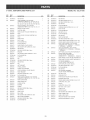
6-1/8-mN.
JOmNTER/PLANER
PARTSLmST
MODELNO.152.217050
KEY
NO,
PART
NO,
DESCRIPTION
QTY,
KEY
NO.
PART
NO.
DESCRIPTION
QTY,
98
STD840812
HEX NUT M8
2
155
STD840610
HEX NUT M8
2
N/A
OR93458
SLIDE ASSEMBLY; (NOT SHOWN)
(CONSISTS OF REF#'S !07, !08, !09, 110, !11,
112, 113, 1!4, 118, 119, 120_ 12!_ 122_ 123_ 124,
125, 128, !27, 128, 129 !35, !38, 137, 138, 139)
1
158
STD523710
HEX HEAD SCREW 3/8-!6 x 1"
4
159
STD833012
HEX HEAD SCREW M6 x 12mm
4
160
STD8406!0
HEX NUT M6
4
161
STD851006
FLAT WASHER M6
4
162
OR90338
CARRIAGE HEAD SCREW 8/16-18 x 1-1/8"
4
N/A
OR93457
FENCE ASSEMBLY (NOT SHOWN)
(CONSISTS OF REF #'S 101,102, 115, 116, 117)
101
OR92175
FENCE (COLOR: BLACK)
1
163
OR92198
DUST CHUTE
1
102
OR90297
CAUTION LABEL
1
164
STD881010
FLAT WASHER M10
4
103
OR90298
1
165
STD541031
HEX NUT 5/16-18
4
104
OR90299
KNOB (COLOR: YELLOW, PANTONE 130)
STUD
1
166
STD881006
FLAT WASHER M6
2
105
OR90298
KNOB (COLOR: YELLOW, PANTONE 130)
1
167
STD8406!0
HEX NUT M6
2
106
OR90299
STUD
1
168
OR90339
DUST CHUTE PORT
1
107
OR90302
SHAFT-LOCK
1
169
STD8330!2
HEX HEAD SCREW M6 x !2ram
2
108
OR90303
BOLT CLAMP
1
170
OR90340
ROUND HEAD FLANGE SCREW #10-24 x 3/8"
4
109
OR90304
FLAT WASHER M12
1
179
OR90340
ROUND HEAD FLANGE SCREW #10-24 x 3/8"
48
1!0
OR92177
NYLOCK NUT M12
1
N/A
OR93462
OR92178
SLIDE FENCE (COLOR: BLACK)
1
1!2
OR90306
HEX SOCKET SET SCREW M6 x 12mm
1
RIGHT SIDE ASSEMBLY; (NOT SHOWN)
(CONSISTS OF:10 - #OR90340, 1 - #OR92203,
2 - #OR93464, ! - #QR92204)
1
1!1
1
OR90463
STD840812
HEX NUT M8
N/A
1!3
1
1!4
STD835030
HEX HEAD SCREW M8 x 30rnm
1
LEFT SIDE ASSEMBLY (NOT SHOWN)
(CONSISTS OF: 10 - #OR90340, 2 - #QR93464,
1 - #OR90347)
1!5
OR92179
BRACKET
2
180
OR90347
LEFT RANEL (COLOR: SILVER, PANTONE 877)
1
1!6
OR92180
HEX SOCKET HEAD SCREW M8 x 14mm
4
181
OR93468
1
1!7
STD85!008
FLAT WASHER M8
4
1!8
OR9218!
SUPPORT
1
FRONT PANEL WITH LABEL;
(COLOR: SILVER, PANTONE 877)
(CONSISTS OF : 1 - #OR922022 & 1 - OR92214)
182
OR92203
1!9
OR92182
P_N
4
RIGHT RANEL (COLOR: SILVER, PANTONE 877)
1
183
OR92202
REAR PANEL (COLOR: S_LVER, PANTQNE 877)
1
184
OR93483
TOP PLATE ASSEMBLY
(COLOR: SILVER, RANTONE 877)
1
189
OR90352
BOTTOM PLATE (COLOR: BLACK)
1
190
STD8330!2
HEX HEAD SCREW M6 x 12mm
8
120
STD835030
HEX HEAD SCREW M8 x 30ram
1
121
STD840812
HEX NUT M8
1
122
OR92183
P_N
2
123
OR92184
LEFT BRACKET
1
124
OR92185
SPECIAL SCREW
1
191
STD881006
FLAT WASHER M6
8
128
OR92186
SPECIAL FLAT WASHER
1
192
STD840610
HEX NUT M6
8
126
OR92187
LEVER ASSEMBLY (COLOR: BL&CK)
1
193
OR93464
LEG SUPPORT ASSEMBLY
4
127
OR92188
RIGHT BRACKET
1
128
OR90320
PAN HEAD SCREW M6 x 12mm
2
196
STD54!
(COLOR: SILVER, PANTONE 877)
HEX NUT 3/8-!8
4
129
STD85!008
FLAT WASHER M6
2
197
OR90354
LEVELING FOOT
4
N/A
OR93459
1
198
OR90388
199
OR92204
PUSH BLOCK HOLDER (COLOR: BLACK)
BUSHING _NSBLATQR
1
1
037
130
OR92189
REAR GUARD ASSEMBLY; (NOT SHOWN)
(CONSISTS OF REF#'S 130, 131, 132, 133, 134)
REAR GUARD BASE
1
203
OR90340
ROUND HEAD FLANGE SCREW #10-24 X 3/8"
3
131
OR92190
REAR GUARD TOP
1
206
OR92206
CAPACITOR, 40 uf, 250V
1
132
OR90323
ACORN NUT M6
2
207
OR92207
MOTOR
1
133
OR90324
BUSHING
2
208
OR92208
CAPACITOR, 300 uf, !25V
1
134
OR90325
SPRH/G
1
2!1
OR90219
KEY 5ram x 5mm x 30mm
1
138
OR92191
HEX HEAD SCREW M6 x 28rnm
1
2!2
OR90359
138
STD840610
HEX NUT M6
1
2!3
OR92211
V BELT(L=88)
MOTOR PULLEY
1
1
137
OR92192
SHAFT LOCK
1
2!4
OR90239
HEX SOCKET SET SCREW M8 x 6mm
2
138
OR90329
BALL KNOB
1
221
OR92214
LABEL, NAME PLATE
1
139
OR92193
HEX SOCKET SET SCREW M5 x 6rnm
4
222
OR92218
LABEL, SPEC PLATE
1
150
OR90332
BELT GUARD ASSEMBLY
1
223
OR90375
PADLOCK AND KEY (NOT SHOWN)
1
153
STD833012
HEX HEAD SCREW M6 x 12ram
2
224
OR92216
_NSTRUCTIQN MANUAL, #21705
1
154
STD851006
FLAT WASHER M8
2
29
6-1/8qN.JOmNTER/PLANER
PARTSUST
MODELNO.152.217050
85
86
--
87
88
/.
90 --I
75
45
30
89
6-1/8qN. JOINTER/PLANER
PARTS UST
MODEL NO. 152.217050
i 32
131
115
i33
27
31
35
i36
6-1/8qN.JOmNTER/PLANER
PARTSUST
MODELNO.152.217050
184
214
212
211
221
190
_
179
181
193 _/
197_
32
213
_n
®
6ol/8 pumg. de ancho
1o1/2 cabalio de fuerza (servicio continuo)
Cabezam de corte de 5000 R.P.M. (sin vemocidad de carga
P
m
No. de Mode_o
152.217050
C
S
PARA SU SEGURIDAD PERSONAL;
Lea y obedezca todas las lnstrucciones
Seguddad y Funcionamiento
antes de
accionar esta MacNmbradora/Cepilladora.
de
Linea de Ayuda al Cliente
1°800°897°7709
Sirvase tenet listo su No, de
Modelo y No, de Serie
Sears,
Roebuck
and Co., Hoffman
Estates,
No. de Pieza OR92216
33
JL 60179 U.S.A.
SEOCION
PAGINA
Garantia .............................................................................................................................................................................
Especificaciones
del Producto
.......................................................................................................................................
lnstrucciones
lnstrucciones
de Seguddad ............................................................................................................................................
de Cone×i6n a Tierra ...............................................................................................................................
lnstrucciones
de Seguddad
Accesorios
para Machimbradoras/Cepiltadoras
..........................................................
y Cone×iones ................................................................................................................................................
Contenido
Conzoca
Especfficas
de ta Caia ........................................................................................................................................................
su Machimbradora/Cepiltadora
lnstrucciones
.......................................................................................................................
de Montaje ................................................................................................................................................
Accionando la Machimbradora/Cepiltadora
...................................................................................................................
Mantenimiento
..................................................................................................................................................................
Gu{a de LocaJizaci6n
lnformaci6n
de Averias .....................................................................................................................................
de Servicio
GARANTiA
COMPLETA
....................................................................................................................
Portada
DE UN ANO
Si este producto faHa debido a defectos matedales o de elaboraci6n dentro de un a_o de la fecha de compra,
1-800-4-MYoHOME®
(en EE.UU.) para tramitar la reparaci6n gratuita del producto.
Esta garantia
al otro.
le otorga derechos
Sears, Roebuck
Posterior
legales especificos,
and Co., Dept. 817 WA, Hoffman
y tambien
Estates,
puede tenet otros derechos
que varian
Ilame al
de un estado
IL 60179
Motor
HP servicio continuo
1-1/2
Voltios
120
Hertzios
60
RPM
3450 R.RM.
(velocidad sin carga)
Dimensiones de la mesa
de alimentaci6n
22 pulg.
Dimensiones de la mesa
de avarice
22-3/8 pulg.
Gu[a de corte
29-1/2 x 4-1/2 pulg.
Inclinaci6n de la Gu[a
45 grados dentro y fuera
Topes positivos de la Gu[a
90, 45 grados
dentro y fuera
RPM del Cabezal de Corte
5000 RPM
Utilice Ia protecci6n correcta de circuitos para evitar los
choques electricos contra su persona y el daf_o a la
Machimbradora/CepilIadora.
La Machimbradora/Cepilladora
est& cableada de fabrica para
un funcionamiento a 120 V, 60 Hz. Conectela a un circuito de
derivaci6n de 120 V, 15 amperios y utilice un fusible de retardaci6n de 15 amperios o un disyuntor de circuitos. El circuito
electrico no puede tener un tamaf_o de cable menor de #14.
Reponga el cord6n de energ[a inmediatamente si se daf_a en
cualquier manera para evitar los choques o incendios.
34
INSTRUCCIONES
DE SEGURIDAD
GENERALES
9,
El funcionamiento de una Machimbradora/Cepilladora
puede
resultar peligroso si se hace caso omiso de la seguridad y del
sentido com0n. El operario debe estar familiarizado con eI
funcionamiento de la herramienta. Lea este manual para
entender su Machimbradora/Cepilladora.
NO OPERE esta
Machimbradora/Cepilladora
si no entiende a cabalidad las
limitaciones de dicha herramienta. NO realice modificaciones
de cualquier tipo a esta Machimbradora/Cepilladora.
UTIUCE PROTECCION OCULAR S_EMPRE. Cualquier
herramienta mecanica puede expulsar escombros hacia
los ojos durante las operaciones, resultando en daflo
ocular grave y permanente. Los anteojos cotidianos NO
son gafas de seguridad. Haga uso StEMPRE de Gafas
de Seguridad (que cumplan con la normativa Z87.1 de
ANSb cuando vaya a utiiizar herramientas mec#,nicas.
Las Gafas de Seguridad estan disponibles en las tiendas
Sears de ventas ai detaL
ANTES DE UTILIZAR LA
MACHUMBRADORA!CEPILLADORA
10. UTILICE PROTECCION AUD_TJVA SlEMPRE. El
aigod6n corriente no representa un dispositivo protector
aceptable. La protecci6n auditNa debe cumplir con la
normativa $3.19 de ANSI.
Para evitar las heridas graves y eI da_o a la herramienta, Iea
y obedezca todas Ias Instrucciones de Seguridad y Operaci6n
antes de operar Ia Machimbradora/Cepilladora.
1.
2,
CONECTE TODAS LAS HERRA_,_ENTAS A TJERRA,
Si la herramienta se suministra con un enchufe de 3
machos, se le debe enchufar a un tomacornentes que
disponga de 3 contactos el6ctricos. E! tercer macho se
uti!iza para conectar la herramienta a tierra y ofrecer
proteccidn contra los choques electricos accidentales.
NO quite el tercer macho. Vea Ias Instrucciones de
Conexi6n a Tierra en la pb,gina 37.
3.
EVITE UN ENTORNO LABORAL PEUGROSO. NO
utilice las herramientas el6ctricas en un entorno h0medo,
ni tampoco las exponga a Iluvia.
4.
NO utilice herramientas
infiamables presentes.
5,
MANTENGA SlEMPRE su zona de trabajo iimpia, bien
alumbrada y organizada. NO TRABAJE en un entorno
con superficies de piso resbalosas a consecuencia de los
escombros, la grasa y la cera.
6,
7,
8,
11. SIEMPRE DESENCNUFE LA NERRAMIENTA DEL
TOMACORRJENTES cuando vaya a realizar ajustes,
cambiar piezas o realizar cualquier clase de mantenimiento.
LEA a consciencia el Manual dei Propietario. APRENDA
c6mo hacer uso de esta herramienta para sus aplicaciones diseF_adas.
12. MANTENGA LOS ESCUDOS DE PROTECC_0N EN SU
SIT_O Y EN BUEN ESTADO DE FUNCIONAM_ENTO,
13. EVITE EL ARRANQUE ACCIDENTAL, Aseg0rese de
que el interruptor de potencia se encuentre en la posici6n
de "APAGADO" antes de enchufar el cord6n de potencia
en el tomacordentes.
14. QUITE TODAS LAS HERRAM_ENTAS DE MANTEN_
MIENTO de la zona inmediata antes de encender la
machimbradora/cepilladora.
15. SOLO UTILICE ACCESORIOS REOOMENDADOS. El
uso de accesorios incorrectos o inapropiados puede
ocasionar heridas graves al operario y ocasionar daSo a
la herramienta. Si tiene dudas, consulte eI manual de
instrucciones que se adjunta con el accesofio especifico.
el6ctricas si hay gases o Fquidos
16. JAMAS DEJE UNA NERRAMIENTA EN FUNCIONAM_ENTO SIN ATENDER. Conmute el interruptor de energfa a la posici6n de apagado. NO abandone Ia herramienta hasta que esta se haya detenido por completo.
MANTENGA ALEJADOS A LOS NINOS Y VISITANTES.
NO permite que haya personas en ia zona inmediata de
trabajo, particuIarmente cuando Ia herramienta el6ctrica
se encuentre en funcionamiento.
17. NO SE PARE SOBRE LA HERRAMJENTA. Puedes producirse heridas graves si la herramienta se vuelca o si
usted hace contacto con la herramienta accidentalmente.
NO FUERCE LA HERRAMIENTA a realizar operaciones
para las cuales no fue disehada. Realizara una labor mas
segura y de mejor calidad si se Ie utiliza para realizar
operaciones para las cuales fue diseF_ada.
18. NO ALMACEN nada por encima ni cerca de Ia maquina
en donde alguien pueda intentar pararse en la herramienta para alcanzarlo.
UTILICE VESTIMENTA APROPIADA. NO vista ropa
hotgada, guantes, corbatas ni arficulos de joyeffa. Estos
art[cu!os pueden quedar atrapados en la maquina
durante Ias operaciones y tirar del operario, atrayendolo
hacia las piezas en movimiento. El usuario debe Ilevar
una cubierta protectiva sobre eI cabeIIo, si tiene cabellera
larga, para impedir el contacto con cualquier pieza en
movimiento.
19. MANTENGA SU EQUILIBR_O. NO se extienda sobre Ia
herramienta. Haga uso de zapatos con suela de caucho
resistente al aceite. Mantenga el piso libre de escombros,
grasa or cera.
20. MANTENGA SUS HERRAMtENTAS CUJDADOSAMENTE, Mantenga sus herramientas Iimpias yen buen
estado. Mangenga afiladas todas las hoias y brocas.
GUARDE ESTAS INSTRUCCIONES.
35
21: REVISE SI HAY PIEZAS DANADAS ANTES DE OADA
USO DE LA HERRAMIENTA. Revise todos los protectores cuidadosamente para comprobar que funcionan
correctamente y que no estan dahados, y que reatizan
sus funciones diseSadas correctamente. Revise el alineamiento, la fijaci6n o Ia ruptura de bs piezas en movimiento. Cualquier protector u otra pieza que se encuentre
daSada debe repararse o reemplazarse inmediatamente.
DIRECTRICES
PARA
LAS EXTENSUONES ELECTRICAS
Mientras menor sea eI n0mero de calibre, mayor sera el
dib,metro de la extensi6n etectrica. Si tiene dudas sobre las
dimensiones correctas de una extensi6n etectrica, utilice una
extension mas corta y gruesa. Una extensi6n de tama_o muy
reducido producira un baj6n en la tension de I[nea, resultando
en la perdida de energfa y el sobrecalentamiento. USE SOLO
UNA EXTENSION ELECTR_CA DE TRES HILOS CON
ENCHUFE DE CONEXION A TIERRA DE TRES MACHOS Y
RECEPT._CULO DE TRES MACHOS QUE ACEPTE EL
ENCHUFE DE LA HERRAMIENTA.
22. HAGA SUE TALLER A PRUEBA DE N_NOS quitando
las Ilaves deI interruptor, desenchufando las herramientas
de los tomacorrientes y mediante el uso de candados.
23. NO OPERE LA HERRAM_ENTA BAJO LA _NFLUENC_A
DE LAS DROGAS O DEL ALCOHOL.
Si esta usando una e×tensiOn e{ectrica a la intemperie,
aseg0rese de que est6 marcada con el sufijo "W-A" ("W" en
Canada) para indicar que es aceptabb para el uso a la
intemperie.
24. AFIANCE TODO EL MATER_AL Siempre que resulte
posible, utilice abrazaderas o plantilIas para asegurar el
material. Esto ofrece mayor seguridad que intentar
sujetar el material con sus propias manos.
Aseg_3rese de que su e×tensiOn e_ctrica este correctamente dimens{onada
yen buenas condiciones electricas.
Reponga siempre aria extensi6n electrica dafiada o haga que
an individuo competente Ia repare antes de utilizada.
25. MANT¢:NGASE ALERTA, FIJESE EN LO QUE EST',
HAC_ENDO Y UTILICE SENTIDO COMON CUANDO
VAYA A OPERAR UNA HERRAM_ENTA MECAN_CA.
NO UT_UCE UNA HERRAM_ENTA CUANDO SE
ENCUENTRE CANSADO O BAJO LA INFLUENC_A DE
DROGAS, ALCOHOL O MEDICAMENTOS. Un momento
de descuido durante ia operaci6n de bs herramientas
mecanicas puede resultar en heridas personales graves.
Proteja sus e×tensiones e_ctricas
contra los objetos
fHosos, el calor excesivo y las zonas hOmedas o mojadas.
26. UTJL_CE S_EMPRE UNA CARETA DE POLVO PARA
_MPED_R LA ASP_RACION DE POLVO PEMGROSO O
PARTICULAS AEREAS induyendo polvo de madera,
potvo de silice cristalina y polvo de asbesto. Aleje las
partfculas de la cara y dei cuerpo. Siempre haga uso de
la herramienta en zonas con buena ventiIaci6n y proporcione la extracci6n apropriada deI polvo. Utilice un sistema de recolecci6n de polvo siempre que sea posible.
La exposici6n al polvo puede causar daho respiratorio
grave y permanente u otras heridas, incluyendo silicosis
(una enfermedad pulmonar grave), cancer y Ia muerte.
Evite respirar el polvo y evite ei contacto prolongado con
el polvo. El permitir Ia entrada del polvo en la boca o los
ojos, o que permanezca sobre su pieI, puede promover la
absorci6n de material da_ino. Haga uso siempre de dispositNos de protecci6n respiratoria aprobados por
NIOSH/OSHA con buen ajuste y apropiados para la
exposici6n al polvo; lave las zonas expuestas con jab6n
y agua.
FUNCIONAMIENTO A 120 VOLTIOS SOLAMENTE
25 PIES
DE LARGO
50 P_ES
DE LARGO
100 P_ES
DE LARGO
0 to 6 Amperios
18 AWG
16 AWG
16 AWG
6 to 10 Amperios
18 AWG
16 AWG
14 AWG
10 to 12 Amperios
16 AWG
16 AWG
14 AWG
12 to 15 Amperios
14 AWG
12 AWG
No se
recomienda
FUNCIONAMIENTO A 240 VOLTIOS SOLAMENTE
27. UTIUCE UNA EXTENSION ELECTR_CA CORRECTA Y
EN BUEN ESTADO. Cuando vaya a hacer uso de una
extensi6n etectrica, aseg0rese de utilizar una que sea Io
suficientemente fuerte como para transportar Ia corriente
a ser utilizada por su herramienta. La siguiente tabla presenta las dimensiones correctas a utiIizarse de acuerdo
con Ias dimensiones de Ia extension y la ciasificaciOn de
amperaje en la placa de notaciones. Si tiene dudas,
utilice la siguiente extension de mayor calibre.
36
25 P(ES
DE LARGO
50 P_ES
DE LARGO
100 P(ES
DE LARGO
0 to 6 Amperios
18 AWG
18 AWG
16 AWG
6 to 10 Amperios
18 AWG
18 AWG
14 AWG
10 to 12 Amperios
16 AWG
16 AWG
14 AWG
12 to 15 Amperios
14 AWG
12 AWG
No se
recomienda
USE SOLO UNA EXTENSKSN EL¢:CTR_CA DE TRES HJLOS
CON ENCHUFE DE CONEXJON A TIERRA DE TRES
MACNOS Y RECEPTACULO DE TRES MACNOS QUE
ACEPTE EL ENCNUFE DE LA NERRAMIENTA.
ESTA HERRAM_ENTA DEBE ESTAR CONECTADA A
TIERRA DURANTE EL USO PARA PROTEGER AL
OPERAR_O CONTRA LOS CHOQUES ELC;CTR_COS.
REPONGA UN CORDON DANADO
tNMEDJATAMENTE.
EN EL CASO DE UN MALFUNCIONAMIENTO
O AVERiA, Ia
conexi6n a tierra ofrece ei trecho de menor resistencia para Ja
corriente electrica y reduce el riesgo de choque el6ctrico.
Esta herramJenta viene equipada con un cord6n de energ(a
que tiene un conductor de conexi6n a tierra del equipo y un
enchufe de conexi6n a tierra. El enchufe DEBE estar enchufado a un tomacorrientes que coincida con el mismo y sea
conectado a tierra en conformidad con TODOS los c6digos y
ordenanzas en el _4mbito local.
PARA LAS MAQU_NAS CONECTADAS A TJERRA Y CON
CORDON DISENADAS PARA EL USO EN UN CIRCU_TO
DE SUM_NtSTRO QUE D_SPONGA DE UNA CLASJFJCAC_ON NOMINAL MENOR A LOS 150 VOLTJOS.
Esta herramienta est4, disehada para el uso en un circuito
que tiene un tomacorrientes conforme a !o iJustrado en la
FIGURA 1A. La FJGURA 1A muestra un enchufe el6ctrico de
3 alambres y un tomacorrientes con conductor de conexi6n a
tierra. Si no hay un tal tomacorrientes disponible, puede
hacerse uso provisional de un adaptador como el que
aparece en Ia FIGURA 1B para conectar este enchufe a un
tomacorrientes de 2 contactos que no este conectado a tierra.
El adaptador dispone de una orejeta rigida que se extiende
deI mismo y que DEBE estar conectado a una conexi6n a
tierra permanente, taI como un tomacorrientes debidamente
conectado a tierra. ESTE ADAPTADOR ESTA PRONJBJDO
EN CANADA.
NO MODIFIQUE EL ENCHUFE SUMJN_STRADO. Si no cabe
en el tomacorrientes existente, haga que un eJectrJcista competente instale el tomacorrientes apropiado.
LA CONEXI6N EL#CTRJCA _NCORRECTA del conductor de
conexi6n a tierra deI equipo puede resultar en el petigro de
choques el6ctricos. El conductor con el aJslante verde (con o
sin rayas amarillas) es el conductor de conexi6n a tierra del
equipo. NO conecte el conductor de conexi6n a tierra del
equipo a una terminaci6n con corriente si se requiere Ia
reparaci6n o el reemplazo del cord6n de energ[a o del
enchufe.
PRECAUCJON: Asegurese en todos los casos de que el
tomacorrientes en cuesti6n este debidamente conectado a
tierra. Si no est_ seguro, haga que un eJectricista competente
revise el tomacorrientes.
CONSULTE con un electricista competente o personal de
servicio si no entiende completamente las instrucciones de
conexi6n a tierra, o si no est,4 seguro si Ja herramienta se
encuentra debidamente conectada a tierra.
E! motor suministrado con su Machimbradora
un motor de voltaje doble de 120/240 voltios,
nante de 60 hertzios y monof_sico. Se env[a
funcionamiento a 120 voltios. Jamas conecte
verde de conexi6n a tierra a una terminaci6n
OR GASTADO
Et motor suministrado con su Machimbradora / CepilJadora es
un motor monof&sico de doble voltaje, 120/240 voltios. Si
desea hacer uso de su Machimbradora / Cepilladora a 240
vottios, ser& necesario reconectar los avances dentro de la
caja de empalmes del motor siguiendo el diagrama de
cableado que aparece en Ja cubierta de Ja caja de empalmes
deJ motor.
/ CepilIadora es
corriente aitercableada para el
el alambre
con corriente.
ASEGURESE de que el motor este desconectado de la
fuente de energfa antes de reconectar Jos avances del motor.
Fig. IA
Fig. 1B
120 Vo_tios
120 Vo_tios
tomacorrientes
para 3 machos
conductor de
conexi6n a tierra
conductor de
conexi6n a tierra
cord6n electrico de 3 hilos
cord6n e!_ctrico de 3 hilos
37
orejeta del
adaptador
de conexi6n
a tierra
0
tomacorrientes
para 2 machos
Tambien resulta necesario reemplazar el enchufe de 120
voltios suministrado con el motor por un enchufe de clasificaci6n UL/CSA adecuado para el funcionamiento a 240
voItios y Ia corriente clasificada de Ia machimbradora /
cepilIadora. Comun[quese con un electricista local competente para los procedimientos correctos para instaiar e!
enchufe. La machimbradora / cepilladora debe cumplir con
todos Ios c6digos eIectricos Iocales y nacionales tras la
instaIaci6n del enchufe de 240 voltios.
240 Vo_tios
MANTENGA las cuchilIas del cabezal de corte afiladas y
libres de moho y alquitrb, n.
4.
ANTES de arrancar la maquina, revise el protector det
cabezal de corte para asegurarse de que no esta daRado
y que funciona libremente.
5.
La machimbradora / cepiliadora con enchufe de 240 voltios
s61o debe conectarse a un tomacorrientes que tenga Ia
misma configuraci6n que ei enchufe iIustrado en Ia
FIGURA 2. No existe ningOn adaptador disponible con el
enchufe de 240 voltios ni tampoco deber[a utilizarse uno.
Fig. 2
3.
caja de saWdas
conectada a tierra
machos portadores
de corriente
O
ASEGURESE de que eI cabezat de corte expuesto
detrAs de la gu[a este protegido, especialmente durante
la realizaci6n de operaciones de machimbrado cerca del
borde.
6.
JAMAS realice operaciones de machimbrado ni de
acepillado con el protector del cabezal de corte fuera de
sitio.
7.
ASEGURESE de que las mesas de alimentaci6n y
avance de salida esten apretadas antes de arrancar la
maquina.
8.
JAM_,S arranque la maquina con ei material haciendo
contacto con el cabezat de corte.
9.
SIEMPRE sujete el material firmemente contra las mesas
y la guia.
10. JAMAS realice operaciones °'A MANO LIBRE', Io que
significa el hacer uso de sus manes para apoyar o guiar
el materia!. SlEMPRE utilice la gu[a para colocar y
orientar el matefiaI.
macho de conexi6n a tierra es
el mas largo de los 3 machos
11. EVlTE las operaciones y posiciones manuaies torpes en
donde un desiizamiento repentino pueda hacer que su
mano entre en contacto con el cabezal de corte.
12. SIEMPRE utilice bloques de reten/empuje para el
machimbrado de materiaies de menos de 3 putgadas
de alto o el acepillado de materiales mb,s delgados
que 3 pulgadas.
ASEGURESE de que el tomacorrientes en cuesti6n este
debidamente conectado a tierra. Si no esta seguro, haga que
un electricista competente revise el tomacorrientes.
13. NO REAUCE operaciones de machimbrado sobre matedales mas cortos que 10 puigadas, m_.s angostos que
3/4 de pulgada o con menos de 1/2 puigada de grosor.
Esta Machimbradora / Cepifladora esta diseF_ada s61o para el
use en interiores. No la deje expuesta a la Iluvia ni haga use
de ella en sitios hOmedos.
14. JAMAS realice una operaci6n de acepillado sobre matedales mas cortes que 10 puigadas, m_.s angostos que
3/4 de pulgada o con menos de 1/2 puigada de grosor.
INSTRUCCIONES
DE SEGURIDAD
ESPECiFICAS
PARA LAS
MACHUMBRAZ)ORASiCEPILLAZ)ORAS
15. JAM,_S efectue un corte de machimbrado o acepiiiado
mas profundo que 1/8 pulg. En los cortes mayores que
1-1/2 putg. de ancho, ajuste la profundidad de corte a
1/16 puig. o menos para evitar la sobrecarga a la
maquina y reducir las posibilidades de un contragolpe
(trabajo arroiado contra usted).
El funcionamiento de cualquier Machimbradora/Cepilladora
puede resultar en la expuIsi6n de chispas hacia sus ojos, Io
que puede resultar en dare grave a los oios. UTIUOE SIEMPRE Gafas de Seguridad que cumpIan con la normativa ANSi
Z87.1) al operar la Machimbradora!Cepilladora.
Las Gafas de
Seguridad estan disponibtes en Ias Tiendas Sears de Ventas
aI DetaL Aparte los putgares y dedos del cabezal de corte.
1.
2.
16. MANTENGA la distancia correcta entre la superficie de
la mesa de avance de salida y el circulo de corte de las
cuchillas.
ADVERTENCIA: No opere la machimbradora/cepilIadora
hasta que se encuentre completamente ensamblada e
instalada de acuerdo con las instrucciones.
17. APOYE ei materia! debidamente en todo memento
durante ia operaci6n. Mantenga control del materiat en
todo memento.
St NO ESTA completemente familiarizado con el funcionamiento de las machimbradoras/cepiIladoras,
solicite
el asesoramiento de su supervisor, instructor u otra
persona calificada.
18. NO empuje el material nuevamente sobre el cabezal de
corte hacia la mesa de alimentaci6n.
38
19. NO trate de realizar una operaci6n anormal o poco
utilizada sin e! estudio debido y e! uso de retenes/
bloques de empuje, montaje, fi]aciones, topes, etc.
[ncluyendo silicosis (una enfermedad pulmonar grave),
cancer y la muerte. Evite aspirar el polvo y evite el contacto prolongado con el polvo. El permitir que el polvo
penetre su boca u ojos, o que permanezca sobre su piel,
podra promover la absorci6n de materiales nocivos.
Utilice siempre Ia protecci6n respiratoria aprobado por
NIOSH / OSHA, debidamente ajustada y correcta para la
exposici6n aI polvo; lave la zona expuesta con agua y
jab6n.
20. APAGUE el suministro de energ[a antes de ajustar la
machimbradora.
21. DESCONECTE Ia machimbradora/cepilladora
de la
fuente de energ[a antes de rendir servicio y limpie la
m_iquina antes de dejarla.
26. Hay INFORMACtON ADICIONAL acerca de Ia operaci6n
segura y correcta de este producto disponible de:
22. ASEGURESE de que Ia zona de traba]o este limpia
antes de abandonar la m_iquina.
Power Tool Institute
dnsituto de Herramientas Mecanicas)
1300 Summer Avenue
Cleveland, OH 44115-2851
www.powertoolinstitute.org
23. Sl cualquier parte de su machimbradora Ilegase a faltar,
o queda dahada, o falIa en cualquier manera, o s[ cualquier componente electrico deia de funcionar correctamente, apague el interruptor y quite el enchufe deI
tomacorrientes. Reponga las piezas ausentes, da_adas
o averiadas antes de reanudar la operaci6n.
National Safety Council
1121 Spring Lake Drive
Itasca, IL 60143-3201
American National Standards institute
25 West 43rd Street, 4th Floor
New York, NY 10036
www.ansko_
24. EL USO de conexiones y accesorios no recomendadas
por Delta puede conllevar el peligro de heridas.
ANSI 01.1 Requisitos de Seguridad para
Maquinas de Ebanisteffa, y los reglamentos del
U.S. Department of Labor
www.osha.ggv_
25. El USO de esta herramienta puede generar y dispersar
polvo u otras particulas a6reas, [ncluyendo polvo de
madera, polvo de silice cristalino y polvo de asbesto.
Aleje las part[culas de! rostro y del cuerpo. Opere
siempre Ia herramienta en una zona que goce de buena
ventilaci6n y proporcione Ia remoci6n correcta del polvo.
Utilice un sistema de recolecci6n de polvo siempre que
sea posible. La exposici6n al polvo puede ocasionar
daBo respirator[o grave y permanente u otras heridas,
ACCESORIOS
27. GUARDE ESTAS INSTRUCCIONES. Refierase a elias
con frecuencia y utiliceJas para adiestrar a otros.
DISPONIBLES
Sears podra recomendar
listados en ese manual.
Visite su Departamento de Ferreteffa de Sears o consutte el
Catalogo de Herramientas Mecanicas y de Mano para los
siguientes accesodos:
otros accesorios que no aparecen
Consulte con su Departamento de Ferreter[a de Sears local o
consulte el Catalogo de Herramientas Mecanicas y de Mano
para otros accesofios:
ARTICULO
No utilice ning0n accesorio a menos que haya le[do el
manual del Propietario para dicho accesorio.
Cuchillas de repuesto
BIoques de empuje de repuesto
S61o utilice los accesorios recomendados por Sears para
esta Machimbradora/Cepilladora.
El uso de otros accesorios
podra ocasionar heridas graves y daRar la Machimbradora/
Cepilladora.
39
DESEMBALAJE
Y REVISION
DEL CONTENIDO
PRECAUCK_N: NO UTlUCE acetona, gasolina ni diJuyente
de laca para quJtar los revestimientos protectivos.
4.
La Machimbradora / Cepilladora es una maquina pesada. Se
requieren dos personas para desembalarla y Ievantarla. Esta
maquina requerir_, cierta cantidad de ensamblaje. Para
reaJizar el ensamblaje necesitara un destornillador Phillips #2
y Jlaves de boca de 8 ram, 10 mm, 14 mm, 16 mm, 17 mm y
19 mm (no incluidas). Se suministran Jlaves hexagonales de
2.5 mm, 3 mm, 4 mm y 6 mm.
1.
Retire todas Ias piezas de Ia caja y cot6quelas sobre una
superficie de trabajo Iimpia.
2.
Se requieren dos o mas personas para levantar la
Machimbradora / Cepilladora y sacada de la caja.
3.
Retire todos los materiaJes protectivos y revestimientos
de las piezas. Los revestimientos protectivos podr_.n
quitarse rociando WD-40 sobre una pieza y Iimpiandola
con un paho suave. Podrb_ser necesario repetir este
procedimiento varias veces antes de que pueda quitarse
per completo todo el revestimiento protective.
Fig. 2-1
Tras la limpieza, apJique una cera automotriz de buena
calidad sobre cualquier superficie sin pintar. Aseg0rese
de pulir la cera antes del ensamblaje.
Compare las piezas con Ias figuras 2-1, 2-2 y 2-3.
Compruebe que todos los art[culos esten completos
antes de descartar Jacaia de env[o. Si faltan piezas,
comun[quese con la L[nea de Ayuda at Cliente al
1-800-897-7709. S[rvase tener listo su n0mero de pieza.
Los n0meros de pieza pueden Iocalizarse en la secci6n
de la Lista de Piezas de su Manual de Instrucciones.
Para evitar heridas, NO encienda Ia Machimbradora /
Cepilladora hasta que todas las piezas hayan side montadas
correctamente. Si existen piezas daF_adas, o si faltan piezas,
NO la utilice hasta que se hayan obtenido y montado todas
las piezas.
3
2
4
11
10
8
9
Panel delantero
Aviso: este panel JJevaJaetiqueta Craftsman
Professional.
6.
Placa inferior
7.
Conducto de poJvo
2.
Panel trasero
8.
BIoques de empuje (2)
3.
Ensamblado
9.
4.
Ensamblado del panel Iaterai izquierdo
Aviso: el ensamblado del panel lateral izquierdo tiene el
agujero cuadrado de gran tamaBo.
Puerto del conducto de polvo
Aviso: el Puerto deI Conducto de Polvo s6Io debe
ensamblarse si se va a utilizar un recolector de polvo con
esta Machimbradora / Cepilladora.
5.
Placa superior
del panel lateral derecho
10. Protector de la polea del cabezaI de corte
11. Portador del bloque de empuje
4O
Fig. 2-2
12
12. EnsambIado
de machimbradora
13. EnsambIado
del motor
14, Gufa
15. Ensamblado
gu[a
de biselado de la
16. Polea del motor
17. Ensamblado del interruptor de
ENCENDDO / APAGADO
18. Protector del cabezal de corte
19. Asidera de Ia mesa de avance
directo
18
17
20. Asideras de Ia gu[a (2)
22
21. Protector trasero del cabezal de
corte
22. Correa en "V"
20
21
Fig. 2-3
23. Pies niveJadores con tuerca hexagonaJ (4)
24. TornilIo de cabeza hexagonal
3/8-16 x 1 pulg. (4)
25. TornilIo de cabeza de carrocerfa
5/16-18 x lq/8 pulg. (4)
26. Arandela plana M10 (4)
27. Tuerca hexagonal 5/16-18 (4)
28. Tuerca de cabeza hexagonal
M6 x 12 mm (16)
©©©
@@@
29. Arandela plana M6 (16)
30. Tuerca hexagonal
M6 (16)
31. TornilIo de cabeza hueca hexagonal
M8 x 30 mm (2)
29.......@ © ©©©©
@ @@@@
32. ArandeIa plana M8 (2)
33. Tuerca hexagonal
©
@
@
(_
32
M8 (2)
34. Arandela de cierre M10 (3)
35. Arandela plana M10 (3)
36. Tuerca hexagonal
©
M10 (3)
©
©
@®
©©©©
@@@@
@@
37. TorniIIo de pestaha de cabeza redonda
#10-24 x 3/8 pulg. (35) (no ilustrado)
38. Llave hexagonal 2.5 mm (no ilustrada)
39. Llave hexagonal 3 mm (no ilustrada)
40. Llave hexagonal 4 mm (no ilustrada)
41. Llave hexagonal 6 mm (no ilustrada)
41
36
3
7
10
12
13
1. Mesa de avarice de salida
10. Escala de profundidad de corte
2, Gu[a
11. Bloques de empuje
3. Agarradera de cierre de la desiizadera
de la gufa
12. Portador de bloque de empuje
13. Estante encerrado
4. Agarradera de la gu(a
5. Bot6n de restablecimiento
termico
14. Pies niveladores
6. Bot6n de ENCENDDO/APAGADO
15. Salida del Conducto de PoNe
7. Protector del cabezal de corte
Aviso: ei Puerto deI Conducto de Polvo s61o debe
ensamblarse si se va a utilizar un recolector de polvo con
esta Machimbradora / Cepilladora.
8. Mesa de avance directo
9. Agarradera de ajuste de altura de la mesa de avance
directo
16. Agarradera de ajuste de altura de la mesa de avance de
salida.
42
Fig. 4-2
I
PARA EVJTAR HERJDAS GRAVES Y DANO A LA MACHII_BRADORA 1 CEPILLADORA:
1.
NO monte !a machimbradora / cepii!adora hasta que este
seguro de que la herramienta NO esta enchufada.
2,
NO monte !a machimbradora / cepiHadora hasta que este
seguro de que eI interruptor de energfa se encuentre en
la posici6n de "APAGADO".
3.
NO monte !a machimbradora / cepii!adora hasta que
haya le[do y entendido este Manual de hstrucciones
cabalmente.
4.
NO monte !a machimbradora
o si estan daRadas.
ENSAMBLADO
/ cepiiladora si faltan piezas
DEL ESTANTE
Fig. 4-1
C
C
G
13"
4.
A
Monte !a placa superior (J) a! ensamblado deI estante (G)
con cuatro torniHos de cabeza hexagonal 3/8-16 x 1 pulg.
(R). No apriete el herramental por compteto en este
momento. Aviso: AsegOrese de que !a p!aca superior este
orientada con el agujero de ensamblaje sencillo (K) hacia
el ensamblado de! panel lateral izquierdo (A) y los dos
agujeros de ensamblaje (L) hacia el ensamblado deI
panel lateral derecho (H) seg0n Io ilustrado en !a Figura
4-3.
R
Fig. 4-3
R
F
E
N
D
B
Coloque el ensamblado del panel lateral izquierdo (A)
sobre una superficie !impia conforme a !o ilustrado en la
Figura 4-1. Aviso: El ensamblado del panel lateral
izquierdo tiene el agujero cuadrado de gran tamaflo (B)
en el mismo.
2.
Monte la placa inferior (C) aI ensamblado del panel
latera! izquierdo usando cuatro tornillos de cabeza
hexagona! M6 x 12 mm (D), arandelas p!anas M6 (E) y
tuercas hexagonales M6 (F). No apriete el herramenta!
completamente en este momento. Aviso: La p!aca inferior
debe ensamblarse aI fondo del ensamblado det panel
lateral izquierdo. Et fondo deI panel lateral izquierdo se
encuentra 13 pu!gadas desde el fondo del agujero
cuadrado seg0n Io ilustrado en la Figura 4-1.
3.
Co!oque el ensamblado del estante (G) en posici6n vertical y monte el ensamblado deI panel lateral derecho (H)
a !a placa de fondo (C) utilizando pare el!o cuatro torniF
los de cabeza hexagonal M6 x 12 ram, arande!as planas
M6 y tuercas hexagonales M6. No apriete el herramentaI
completamente en este momento. Aviso: Asegurese de
orientar el agujero deI cord6n de energ[a (b hacia la
parte superior del ensamblado del panel !ateral derecho.
Ver la Figura 4-2.
5.
43
Acabe de asegurar los ensamblados de los pane!es
laterales izquierdo y derecho a los paneles superior e
inferior mediante et uso de cuatro torni!!os de pestaha de
cabeza redonda #10-24 x 3/8 pu!g. Los r6tulos (P) en
las Figuras 4-3 y 4-4 muestran los sitios que deben ser
afianzados.
Fig. 4-4
ENSAMBLADO
DEL MOTOR
P
NO monte Ia Machimbradora/Cepilladora
hasta que este
seguro de que el interruptor de energ[a se encuentre en la
posici6n de APAGADO y el cord6n de energ[a este desconectado de la fuente de energ[a.
N
A
6.
Coloque el ensamblado del estante sobre su ensamblado
det panel lateral izquierdo (A). Ver Ia figura 4-4.
7.
Coloque el conducto de polvo (M) entre las pestaSas (N)
de la ptaca superior. Ver las Figuras 4-3 y 4-4. Uti!ice
cuatro tomi!los de cabeza hexagonal M6 x 12 ram,
arandelas planas M6 y tuercas hexagonaIes M6 para
asegurar el conducto de polvo a Ia placa superior. No
apdete eI herramental compIetamente.
8.
Asegure el fondo del conducto de polvo (O) aI panel
lateral izquierdo con dos torniIIos de cabeza hexagonal
M6 x 12 mm, arandelas planas M6 y tuercas hexagonales M6. Ver la Figura 4-4.
9.
Apriete los seis tornlllos afianzando el conducto de polvo
al estante.
Fig. 4-5
1.
Monte Ia polea del motor (A) sobre el eje del motor (B).
Aseg0rese de que los dos tornilIos de fijaci6n (C) en la
polea del motor esten rebajados de tal manera que la
polea del motor pueda deslizarse sobre el eje del motor.
Ver Ia Figura 5-1.
2.
Allnee Ia Ilave cuadrada de 5 mm x 5 mmx 30 mm que
ya se encuentra en el eje del motor con la chaveta de la
polea. Deslice la polea deI motor sobre el eje del motor
hasta que la polea quede pareja con el extremo deI eje
del motor conforme a !o ilustrado en Ia Figura 5-1.
Apriete ambos tornillos de fijaci6n (C) en este momento.
Fig. 5-2
C
D
p
X\
H
E
10. Enrosque los cuatro pies niveladores usando Ias tuercas
hexagonales (P) en !os agujeros roscados (Q) en los
ensamblados de paneles laterales. Ver la Figura 4-5.
44
3.
Coloque el ensamblado det motor (D) sobre et conducto
de polvo (E). Asegurese de que la polea deI motor (C)
este colocada en el mismo lado que Ia abertura de la
correa (F) en la placa superior. Ver la Flgura 5-2.
4.
Afiance el ensamblado
con cuatro tornillos de
(G), arandelas ptanas
5/16-18 (I). No aprlete
8.
Coloque el ensamblado deI estante en posici6n vertical y
ajuste los pies nlveladores para que el estante quede
piano sobre el plso.
del motor al conducto de polvo
carrocer[a 5/16-18 x 1-1/8 pulg.
M10 (H) y tuercas hexagonales
e! herramentaI completamente.
Fig. 5-3
Co!oque la Machimbradora / Cepilladora (A) sobre el
estante (B) de manera que los tres gorrones situados per
debajo de la base de Ia machimbradora queden alineados con las tres ranuras en la placa superior deI estante.
Ver la Figura 6-1.
1.
K
L
Afiance la machimbradora al estante con tres arandeIas
planas M10, arandelas de cierre M10 y tuercas hexagonales M10. Aviso: Se puede conseguir acceso a dos de
los gorrones en la base de Ia machimbradora dentro deI
estante. Se puede conseguir acceso al tercer gorr6n s61o
a traves de la abertura det conducto de polvo en el panel
lateral. Afiance todo el herramental de manera segura.
2.
ENSAMBLADO
DE LA AGARRADERA
LA MESA DE AVANCE DIRECTO
6.
Comience a insertar dos tornilIos de pestai_a de cabeza
redonda #10-24 x 3/8 pulg. (J) en e! panel lateraJ derecho. AtornflleIos a la mitad soIamente.
7.
DesJice las ranuras (K) del portador del bloque de
empuie (L) sobre los dos tornilIos (J) en el panel lateral.
8.
Conecte el braze (M) deI portador del bJoque de empu]e
al agujero (N) en el panel lateral usando un tornillo de
pestaha de cabeza redonda 10-24 x 3/8 pulg.
9.
En este momento, afiance seguramente
todo el herramentaB del eetante, salvo por emherramentaJ de
ensamblaje demmotor,
DE
Fig. 7-1
A
ENSAMBLADO
DE LA
MACHIMBRADORA
/ CEPILLADORA
@
C
B
©
NO monte la Machimbradora / Cepilladora hasta que este
seguro de que el interrupter de energfa se encuentre en Ia
posici6n de APAGADO y el cord6n de energfa este desconectado de la fuente de energfa.
PRECAUCION: Se requieren dos o mb,s personas para aJzar
la Machimbradora / Cepilladora.
Fig. 6-1
A
45
1.
Monte Ia agarradera de la mesa de avance directo (A)
con la tuerca hexagonal (B) al bloque roscado (C) debajo
de la mesa de avance directo. Ver Ia Figura 7-1.
2.
Cuando la agarradera de Ia mesa de avance directo
este completamente roscada dentro deI bIoque roscado,
apriete la tuerca hexagonal (B) contra el bloque (C).
ENSAMBLADO
DE LA CORREA
ENSAMBLADO
DEL PROTECTOR
EL INTERRUPTOR
NO monte la Machimbradora / Cepilladora hasta que este
seguro de que el interruptor de energ[a se encuentre en Ia
posici6n de APAGADO y eI cord6n de energ(a este desconectado de la fuente de energ[a.
Fig. 8-1
Y
NO monte Ia Machimbradora / Cepilladora hasta que este
seguro de que el interruptor de energ[a se encuentre en la
posici6n de APAGADO y el cord6n de energ[a este desconectado de Jafuente de energ[a.
A
Fig. 9-1
O
D
B
A
G
Mediante el uso de una regla, asegurese de que la polea
del cabezal de corte (A) y la polea del motor (B) esten
alineadas entre sL Ver la Figura 8-1.
2.
Para realizar ajustes a una o ambas poleas, afloje
primero Ios torniIIos de fijaci6n de Ia polea. Mueva la
polea hacia adentro o afuera para realizar el alineamiento oorrecto.
3.
Apriete los tornilios de fijacl6n despues deJ alineamiento
correcto.
4.
Coloque Ia correa (C) a traves de Ia abertura de la correa
(D) en la placa superior y coloque la correa sobre Ia
polea deI cabezal de corte y la polea deI motor. Aviso: El
motor (E) tendrb_ que moverse hacla arrlba a Io largo del
conducto de polvo (F) para permitlr que Ia correa rodee
ambas poleas. Ver la Flgura 8-1.
5.
Tenslone Ia correa moviendo el motor hacla abajo a Io
largo deI conducto de polvo. Avlso: La tensi6n correcta
se obtlene cuando existe una defiexi6n de aproximadamente 1 pulg. en el centro del tramo de la correa, ejerciendo presi6n Iigera con el dedo.
6.
Luego de haber conseguldo Ia tensi6n correcta, revise
nuevamente et alineamiento correcto de Ias poleas.
Luego apriete seguramente el herramental de montaje
deJ motor.
46
1.
Monte el protector de Ia polea de! cabezal de corte (A) a
la placa superior (B) con dos tornilIos de cabeza hexagonal M6 x 12 ram, arandelas planas M6 y tuercas hexagohales M6 y apriete todo el herramentaL Ver la Flgura 9-1.
2.
Monte el ensamblado del interruptor de ENCENDIDO /
APAGADO (C) a la parte posterior de la mesa de avance
directo (D) con dos tornil!os de cabeza hueca hexagonal
M8 x 30 mm, arandelas planas M8 y tuercas hexagohales M8.
3.
Coloque el extremo de tap6n especial (E) del ensamblado del interruptor de ENCENDIDO / APAGADO a trav6.s
de! agujero en el panel lateral y conectelo con e! extremo
de receptacuto especial (F) del ensamblado del motor.
AsegOrese de que esten completamente asentadas
juntas y que no hagan contacto con Ja correa (G).
ENSAMBLADO
DE LA GUiA
Fig. 10-3
NO monte la Machimbradora / Cepilladora hasta que este
seguro de que el interruptor de energfa se encuentre en Ia
posici6n de APAGADO y eI cord6n de energfa este desconectado de la fuente de energfa.
\
\\
\
Fig. 10-1
K
G
H
B
F
E
C
G
Afioje el torni!lo de fijaci6n (A) sobre ei ensamblado de
biselado de la gufa (B) y quite el eje del cierre de Ievas
(C). Quite la abrazadera de pernos (D), la arandela plana
M12 (E) y Ia tuerca hexagonal Nylock M12 (F) del eje del
cierre de levas (C). Ver la Figura 10-1.
5.
2.
Monte las agarraderas (G) a la gufa (H) y al eje del cierre
de levas.
3.
Quite los cuatro tornilIos de cabeza hueca hexagonal M8
x 14 mm (I) y las arandelas planas (J) de Ia gufa. Aviso:
Este herramentaI se utiliz6 para conectar los soportes de
la gufa (K) a la gufa. IMPORTANTE: Aseg0rese de no
cambiar la orientaci6n de los soportes de la gufa.
Una vez que ambos soportes de la gufa hayan sido colocados sobre los pasadores de los soportes de apoyo
delanteros de la gufa, sostenga el ensambIado de biselado de la gufa en posici6n vertical seg0n se iIustra en la
Figura 10-3. Monte los soportes de Ia gufa a la gufa con
los cuatro tornillos de cabeza hueca hexagonal M8 x 14
mm (I) y las cuatro arandelas planas (J) que fueron quitados en e[ PASO 3. No apriete e[ herramental completamente. Aviso: Asegurese de que los soportes de la gufa
permanezcan engranados con los pasadores de los
soportes de apoyo delanteros de la gufa.
Fig. 10-2
Fig. 10-4
K
N
N
4.
CoIoque ambos soportes de gufa (K) sobre los cuatro
pasadores (L) en los soportes delanteros de la gufa (M)
seg0n Io ilustrado en Ia Figura 10-2. Aviso: Afioje Ia
agarradera de cierre de bise[ado (N) y retire Ia perilla de
parada de 90 grados (O) para permitir el movimiento de
los soportes de apoyo deIanteros para el alineamiento de
los pasadores con el soporte de la gufa.
6.
47
Permita que et ensamblado de biselado de la gufa (B)
gire hacia delante seg0n Io ilustrado en Ia Figura 10-4.
Afiance todo et herramental y Ia agarradera de cierre de
biselado (N) de manera segura.
Fig. 10-5
Fig. 10-7
°E
/+
7.
Vuelva a ensamblar el eje de cierre de Ievas (C) desmon+
tado en el PASO 1. Aseg0rese de cotocar la abrazadera
de pernos (D) sobre el eje de[ cierre de levas seg0n Io
[Iustra la Figura 10-5. No monte Ia arandeta plana M12
(E) y la tuerca hexagonal Nylock M12 (F) en este
momento.
8.
Apriete el torn[llo de fijaci6n (A) hasta que se detenga,
luego retroceda 1/2 vuelta. Ver la Figura 10-1.
10+ Monte Ia arandeta plana M12 (E, Figura 10-7) y Ia tuerca
hexagonal Nylock M12 (F) a la abrazadera de pernos
(D). Aseg0rese de que la agarradera del cierre de Ievas
(S, Figura 10-6) este en la posici6n de 1:00 y luego
apriete la tuerca hexagonal Nytock. Esto fija el mecanismo de enclavamiento para Ia deslizadera de la gu[a.
Ahora, la deslizadera de Ia gu[a debe enc[avarse y
desenclavarse con un cuarto de vuelta de Ia agarradera
del cierre de Ievas. Para reatizar el enclavamlento con
menos movimiento, gire la tuerca hexagonal Nytock en el
sentido de las agujas del reloj. Para realizar el enclavamiento con mas movimiento, gire Ia tuerca Nylock contra
el sentido de las agujas de[ reloj.
11+ Revise que la gu[a se enclave y desenclave girando la
agarradera de cierre de levas. Aseg0rese de que et
ensamblado de la gu[a pueda moverse a Io ancho de la
mesa sin arrastre excesivo proveniente de[ mecanismo
de enclavamiento.
Fig. 10-8
Fig. 10-6
H
R
T
S
g.
Coloque con cuidado el ensamblado de [a gu[a (V), que
[ncluye el ensamblado de biselado de la gu[a (B), sobre
la mesa de avarice de satida, segun !o [lustra la Figura
10-6. AsegOrese de que la abrazadera de pernos (D,
Figura 10-7) atraviese la ranura (P, Figura 10-5) en Ia
mesa de avance de salida y que la chaveta (Q, Figura
10-5) este alineada con la Iiave (R).
12. Coloque la gu[a (H) a 90 grados y apriete la agarradera
del cierre de Ievas (S). Consulte Ia secci6n FUNCIONAMENTO DE LA GUIA para ver el procedimiento correcto
para colocar Ia guia.
48
13. Retire los dos tornilIos (T) del ensamblado de biselado de
la guia. Ensamble el protector del cabezaI de corte posterior (U) usando los mismos dos tornillos y aprietelos de
manera segura.
ENSAMBLAJE
DEL PROTECTOR
CABEZAL
DE CORTE
DEL
ENSAMBLAJE
DELANTERO
DE LOS PANELES
Y POSTERIOR
NO monte la Machimbradora / Cepilladora hasta que este
seguro de que el interruptor de energfa se encuentre en Ia
posici6n de APAGADO y el cord6n de energ[a este desconectado de la fuente de energ(a.
NO monte Ia Machimbradora / CepiIladora hasta que est6
seguro de que el interruptor de energfa se encuentre en la
posici6n de APAGADO y el cord6n de energfa este desconectado de Ia fuente de energ[a=
Fig. 11-1
Monte !os tableros delantero (A) y posterior al estante de la
machimbradora con veinticuatro tornilIos de pestaf]a de
cabeza redonda #10-24 x 3/8 pulg. y apriete los tornillos de
manera segura. Ver Figura 12-1.
B
ENSAMBLAJE
DEL PUERTO
CONDUCTO
DE POLVO
DEL
NO monte Ia Machimbradora / Cepilladora hasta que este
seguro de que el interruptor de energ[a se encuentre en la
posici6n de APAGADO y el cord6n de energfa este desconectado de la fuente de energfa.
C
D
Fig. 12-1
A
1=
Quite el tornillo del poste (A) del protector del cabezal de
corte (B)= Ver Figura 11-1=
2.
Conecte el protector deI cabezal de corte a Ia mesa de
avance directo (C) cotocando el poste (A) a traves del
agujero en la mesa de avance directo.
3=
Gire la perilIa (D) en Ia cara inferior de! agujero 1/2 de
vuelta para tensionar e! resorte de retorno. Este resorte
permite el retomo del protector sobre el cabezal de corte
despues de que se haya reatizado el corte.
4=
Alinee la ranura en el poste con el resorte y luego inserte
el poste=
5.
Revise que el protector regrese por completo. Si no Io
hace, retire el protector y a_iada otra 1/2 vuelta a la perilla (D). Luego reponga el protector siguiendo el PASO 4
detallado arriba.
6=
Enrosque el tornillo que fue quitado en el PASO 1 en el
poste dei cabezal de corte. Este tornillo mantiene el protector en su sitio.
B
Si se va a utilizar un recolector de polvo (no incluido) con la
Machimbradora / Cepilladora, conecte el puerto deI conducto
de potvo (B) sobre el orificio deI conducto de polvo en el
panel lateral izquierdo. Utilice cuatro tornillos de pesta_a de
cabeza redonda #10-24 x 3/8 pulg. para afianzar el puerto de
manera segura al panel. Ver Ia Figura 12-1.
tMPORTANTE: NO monte el puerto de! conducto de polvo si
no va a utiIizar un recoiector de polvo. Esto s6to hara que Ias
astillas de madera se atasquen en el conducto de polvo y salgan de nuevo por la abertura del cabezal de corte.
49
PRECAUCI6N
Debe utilizar un circuito electrico aparte para su
Machimbradora / Cepilladora. La Machimbradora /
Cepilladora viene cableada de antemano para el uso a
120 voltios. El circuito no debe ser menor que un alambre de #14 AWG y debe estar protegido por un fusible de
retardaci6n de 15 amperios.
2.
Para encender Ia Machimbradora / CepilIadora, oprima el
bot6n verde de ENCENDIDO (B) una mitad de pulgada.
Aviso: Existe un distintivo de seguridad en el interruptor
para asegurar que el interruptor sea oprimido completamente antes de que pueda arrancar el motor.
3.
Para apagar Ia Machimbradora / CepilIadora, oprima Ia
paleta roja grande de APAGADO (C) o Ievante la paIeta y
presione directamente el bot6n rojo de APAGADO (D).
Ver las Figuras 13-1 y 13-2.
Haga que un eIectricista competente repare o reponga
cualquier cord6n dahado o gastado inmediatamente.
Antes de conectar e! motor a la I[nea de energ[a,
aseg0rese de que el interruptor este en la posici6n de
APAGADO y aseg0rese de que Ia corriente etectrica
tenga Ias mismas caracterfsticas que la placa de notaclones deI motor. Todas Ias conexiones de I[nea deben
hacer buen contacto.
o
ENCLAVANDO EL INTERRUPTOR EN LA
POSlCION DE "APAGADO"
HAGA QUE LA ZONA DEL TALLER SEA A PRUEBA DE
NII_IOS quitando Ias Ilaves de los interruptores, desenchufando las herramientas de los tomacorrientes y mediante el uso
de candados.
El funcionamiento a bajo voltaic o con cordones de
extensi6n largos daBarb, el motor.
ARRANCANDO
Y DETENIENDO
LA
MACHIMBRADORA
/ CEPILLADORA
Fig. 13-2
NO deje la Machimbradora / Cepilladora expuesta a la
Iluvia ni haga uso de ella en sitios h0medos.
i
Z
I
I
ASEGURESE de que todas la piezas hayan sido
ensambladas correctamente y esten en buen estado de
funcionamiento.
MANTENGA
herramientas
Fig. 13-1
las superficies de Ias mesas libres de
y escombros antes de comenzar.
A
C
E
B
D
1.
Cuando la Machimbradora / Cepilladora no est6, en uso,
eI bot6n de ENCENDIDO (B) debe estar encerrojado
para impedir su arranque. Vet Ia Figura 13-2.
2.
Usando el candado (E) incluido con su Machimbradora /
CepiIIadora, Ievante Ia paleta roja de APAGADO (C) y
coloque eI candado a traves de los agujeros en el costado del bot6n de ENCENDDO y luego cierre el candado.
Aseg0rese de que las IIaves hayan sido retiradas deI
candado y colocadas en donde no las pueda encontrar
ningun niF_o.
3.
Para hacer uso de la Machimbradora / Cepilladora,
desencerroje y retire el candado del bot6n de
ENCENDIDO.
r_t_%7 _tiiiii/J
r
C
El interruptor de ENCENDIDO/APAGADO
(A) esta
situado en el poste sobre la mesa de avance directo.
Ver la Figura 13-1.
5O
PRECAUCI6N:
LA PROFUNDIDAD DE CORTE DE 1/2
PULG° SOLO SE UTIUZA EN LAS OPERACIONES DE
CORTE DE ALEFRJZ°
PROTECCION
CONTRA
SOBRECARGAS
TERMICAS
Gire el interruptor de energfa a la posici6n de APAGADO
y desenchufe el cord6n de energfa de su fuente de
energ[a antes de realizar cualquier mantenimiento o
aiuste.
Asegurese de que el bot6n de APAGADO se haya
oprimido antes de pulsar el bot6n de restablecimiento
sobrecarga termica.
3.
Una vez fijada la profundidad de corte, apriete la asidera
de enclavamiento de la mesa de alimentaci6n (A).
Ver Figura 14-1.
4.
El indicador (C) en la escala de profundidad de corte (D)
indica Ia profundidad de corte de la mesa de alimentaci6n. Ver Figura 14-1.
de
E! motor suministrado con su Machimbradora / CepiIIadora
tiene un rele de sobrecarga termica restabIecible (F); ver la
Figura 13-1. Si el motor se apaga durante una operaci6n
(corte del material con rapidez excesiva o usando hojas romas,
use de Ia machimbradora mas alia de sus capacidades o bajo
voltaje) presione la paleta de APAGADO (C) y permita que el
motor se enfrfe entre tres y cinco minutes. Presione el bot6n
de restabIecimiento de sobrecarga termica en el costado del
bot6n de ENCENDIDO /APAGADO. Asegurese de que Ia
zona de trabajo haya side despejada de escombros antes de
reactivar el motor. E! motor podra activarse de nuevo ahora
presionando el bot6n de ENCENDIDO (B).
FUNCIONAMIENTO
DE LA MESA
DE AVANCE DE SALIDA
APAGUE el interruptor de energia y desenchufe el
cord6n de energia de su fuente de energia antes de
realizar cualquier mantenimiento o ajuste,
PRECAUOI6N: Los bordes de la cuchilla son filosos. Evite
tocarlos.
FUNCIONAMIENTO
DE LA MESA
DE AVANCE DIRECTO
1.
APAGUE el interruptor de energfa y desenchufe el cord6n de
energia de su fuente de energia antes de realizar cuaIquier
mantenimiento o ajuste.
Para poder realizar operaciones certeras de machimbrado/cepillado, Ia mesa de avance de salida (A) debe
estar nivetada exactamente con el punto alto (B) de las
cuchillas (C). Ver Figura 15-1.
Fig. 15-1
E
Para izar o baiar la mesa de alimentaci6n, afloje la
asidera de enclavamiento de Ia mesa de alimentaci6n
(A). Para afiojar la asidera, gireta contra e! sentido de
las agujas del reloj. Para apretarla, gire la asidera en el
sentido de las aguias del reloi. Ver Figura 14-1.
A
B
/!
Fig. 14-1
C
D
Para ajustar la mesa de avance de salida (F), afloje el
tornillo de enctavamiento de alas (G) en el dorso de la
mesa de avance de salida. Ver Figura 15-1.
2.
Sujete la agarradera de izado / bajado de la mesa de
avance directo, Iocatizada per debajo de la mesa de
avance directo, y eleve o baje la agarradera. AWSO:
Para Ias operaciones de corte de aIefriz, el pasador de
profundidad de corte m&xima (B) debe desengranarse a
la profundidad de corte de 1/8 putg. Para desengranar,
retire Ia perilIa hacia usted. Esto permitira que la mesa
de avance directo se rebaje a una profundidad de corte
maximo de 1/2 pulg.
51
2.
De pie frente a Jamachimbradora, agarre Ia parte
superior de la gufa entre los soportes de apoyo
delanteros (C) y deslice Ia gufa a Ia posici6n deseada.
3.
Apriete Ia agarradera de levas. AsegOrese de que el protector deJ cabezal de corte (D) regrese y descanse contra
la gufa. Si no, pase a Ia secci6n ENSAMBLAJE DEL
PROTECTOR DEL CABEZAL DE CORTE en las instrucciones de ensamblaje para el procedimiento de ensamblaje.
INCLINANDO
G
4.
5.
6.
LA GUiA
APAGUE el interruptor de energfa y desenchufe el cord6n de
energfa de su fuente de energfa antes de realizar cualquier
mantenimiento o ajuste.
H
La gufa puede inclinarse hasta 45 grados adentro o afuera.
La gufa dispone de topes positives a los 45 grades adentro y
90 y 45 grades afuera.
Gire Ia perilIa de mane (H) !ocalizada debajo de Ja mesa
de alimentaci6n de satida en el sentido de Ias agujas del
retoj para izar Ia mesa, o en et sentido contrario a Ias
agujas del reJoi para bajar Ia mesa. Vet Figura 15-2.
Ajuste
Para revisar el nive! de Ia mesa a Ias cuchillas, coloque
una regla (E) sobre Ia mesa de avance de salida,
extendiendola sobre el centre del cabezal de corte (D).
Vet Figura 15-1. Para comprobar que Ias cuchilJas esten
correctamente instaladas, vea la secci6n "AJUSTES DE
CUCHILLAS".
de Parada
Fig. 17-1
de 90 Grados
Positivos
A
B
Cuando la mesa de avance de salida se encuentre
precisamente nivelada con el punto alto de Ias cuchillas,
apriete el tornilIo de enclavamiento de alas seg0n Io
ilustrado en las Figuras 15-1 y 15-2.
MOVlENDO
LA GUJA
APAGUE el interruptor de energfa y desenchufe el cord6n de
energfa de su fuente de energfa antes de realizar cualquier
mantenimiento o ajuste.
Fig. 16-1
A
C
B
7
Para deslizar Ia guia (A) a Io ancho de la machimbradora, afloje la agarradera del cierre de Ievas (B). Observe
que esta agarradera se enclava y se desenclava con un
cuarto de rotaci6n de la agarradera. Ver la Figura 16-1.
52
1.
Para fijar Ia gufa
mesa, aseg0rese
90 grados (A) se
encuentre dentro
delantero. Ver la
a 90 grados contra Ia superficie de la
pdmero de que Ia perilIa de parada de
haya empuiado hacia adentro y que se
de la ranura (B) del soporte de apoyo
Figura 17-1.
2.
Aseg0rese de que la perilla de parada de 90 grades se
encuentre contra el tornillo de parada positive de
90 grades (C).
3.
Incline la agarradera de cierre de inclinaci6n (D) y utilice
una escuadra exacta para asegurarse de que Ia gufa
este a 90 grades contra la superficie de la mesa.
4.
Si se requiere cualquier ajuste, afloje Jaagarradera de
cierre de inclinaci6n.
5.
Afloje la tuerca de parada (E) y ajuste el tornlllo de
parada a 90 grades positives.
6.
Vuelva a apretar la agarradera de cierre de biselado, y
revise nuevamente que Ia gufa se encuentre a 90 grades
contra Ia superficie de la mesa.
7.
Repita los pasos anteriores hasta que Ia gufa este
correctamente colocada y luego apriete la tuerca de
parada.
Ajuste de Parada
hacia Afuera
de 45 Grados
Positivos
A]uste de Parada
hacia Adentro
Fig. 17-2
de 45 Grados
Positivos
Fig. 17-3
H
A
F
D
1.
Para fijar Ia gu[a a 45 grados hacia adentro contra Ia
superficie de Ia mesa, aseg0rese primero de que se haya
extra(do Ja perilla de parada de 90 grades (A). Vet Ja
Figura 17-3.
2.
Afloje la agarradera de cierre de biselado (D) e incline Ia
guia hacia adelante y contra el torniIIo de parada positiva
de 45 grades hacia adentro (H). Aviso: Este torniIIo de
parada posJtiva no hace contacto con Ja gu(a en eJ lade
de cabeza de! torniHo, sine en el extreme roscado.
3.
Apriete Ja agarradera de cierre de biseIado (D) y revise
que la gu[a se encuentre a 45 grados contra la superficie
de Ia mesa con una escuadra exacta.
4.
S[ se requiere cuaiquier ajuste, afloje Jaagarradera de
cierre de [ndinaci6n.
Si se requiere cualquier ajuste, afloje la agarradera de
derre de [ncJinaci6n.
5.
Afioje la tuerca de parada (I) y ajuste el tom[llo de parada
positiva de 45 grades (H).
5.
Afioje Ia tuerca de parada (G) iIustrada en Ia Figura 17-1
y ajuste et torniIIo de parada positiva de 45 grades (F).
6.
6.
Vuelva a apretar la agarradera de cierre de biselado y
revise nuevamente que la gu[a se encuentre a 45 grades
contra la superfic[e de Ia mesa.
Vue[va a apretar la agarradera de cierre de biseIado y
revise nuevamente que Ia guia este a 45 grades contra
la superficie de Ia mesa.
7.
Repita los pasos anteriores hasta que Ia gu[a este fijada
correctamente y Juego apnete Ja tuerca de parada.
Para fijar Ia gu[a a 45 grades hacia afuera contra Ia
superficie de Ia mesa, aseg0rese primero de que se haya
extra[do Ja perilla de parada de 90 grades (A). Ver la
Figura 17-2.
2.
3.
4.
7.
Afioje Ia agarradera deI cJerre de biseIado (D) e incline la
gu[a hacia atras y contra eI tornilJo de parada positiva de
45 grades hacia fuera (F).
Apriete Ia agarradera deI c[erre de biselado (D) y revise
que Ia gu[a se encuentre a 45 grades contra Ja superficie
de la mesa con una esouadra exacta.
Repita Ios pasos anteriores hasta que Ia guia este fijada
correctamente y luego apriete la tuerca de parada.
53
AJUSTES
DE CUCHILLAS
Fig. 18-2
Para poder reaHzar un trabajo certero, Has cuchHHas
deben estar niveHadas exactamente
con Hamesa de
avarice
de saHda. Ver Figura
H
18-1.
Fig. 18-1
D
D
G
E
Para evitar heridas graves, desconecte
cepilladora de la fuente de energ[a.
4.
S[ una cuchiila (D) se encuentra baja, gire los tornillos de
enclavamiento de cuchiIIas (G) en el sentido de las agujas deI reIoj una mida de vuelta con una IIave de boca de
8 mm (no incluida). PRECALICION: Las cuchillas son
sumamente filosas; tenga mucho cuidado al trabajar con
elias. Ver la Figura 18-2.
5.
Con la regla sobre Ia mesa de avarice de salida y
extendiendose sobre e! centre de! cabeza! de corte, gire
uno u ambos tornillos niveladores (H) con Ia Ilave hexagonal de 2.5 mm (incluida) en el sentido de las aguias
del reloj para elevar la cuchilla hasta que toque la regla.
6.
Aseg0rese de revisar Ia cuchilla en ambas Iocalizaciones
de los tornillos nivetadores. Realice ajustes adicionales
seg0n sea necesario.
7.
S[ una cuchilla (D) se encuentra alta, gire !os tornilIos de
enclavamiento de cuchilIas (G) en el sentido de Ias agujas del reloj una vuetta completa con una Ilave de boca
de 8 mm (no inctuida). PREOAUCK)N: Las cuchillas son
sumamente filosas; tenga mucho cuidado al trabajar con
elias.
6.
Gire ambos tornillos nivetadores (H) contra el sentido de
las agujas del reloj utilizando una Ilave hexagonal de
2.5 mm ([ncluida).
g.
Empuje Ia cuchilIa hacia abajo cuidadosamente,
do para ello un pedazo de madera.
la machimbradora!
PRECAUCION: Los bordes de las cuchillas son filosos. Evite
tocados para prevenir cortaduras.
1.
Baje la mesa de alimentaci6n
cabezak Ver Figura 18-1.
(A) y quite el protector del
2.
Coloque una regla (B) sobre Ia mesa de avarice de
salida (C), extendi6ndola sobre el centro del cabezaI
de corte (E). Ver Figura 18-1.
NO toque el borde fiIoso de Ias cuchillas. Use un destornillador o Ilave para ayudar a girar el cabezal de corte.
3.
Gire el cabezal de corte cuidadosamente con Ias manes.
Las cuchilIas (D) deben tocar la regia. Revise ambos
lades de las cuchillas (F). Ver Figura 18-1.
AVISO: Las cuchilIas no deben extenderse mAs de
1/16 pulg. del cabezal de corte. Ver Figura 19-1.
utilizan-
10. Aseg0rese de revisar Ia cuchilIa en ambas Iocalizaciones
de los tornillos niveladores. Realice ajustes adicionales
seg0n sea necesario.
11. Apriete todos los tornillos de enclavamiento de cuchillas
girandolos contra el sentido de las agujas del reloi.
12. Aseg0rese de que las tres cuchillas hayan side revisadas
a Io largo de Ia superficie de la mesa de avance de
salida y que esten niveladas.
13. Hnstale el protector deI cabezal de corte y eleve la mesa
de avarice directo a su profundidad de corte correcta.
54
EXTRACCK)N
DE CUCHILLAS
REEMPLAZO
PRECAUClON: Para prevenir cortaduras, se debe tener
cuidado ai quitar, reempJazar y recolocar las cuchiJJas.
DE CUCHILLAS
Fig. 20-1
Fig. 19-1
1/!6 putg.
de tas cuchittas
F
de proyecci6n
del cabezal de corte
1/16"
B
D
1
D
A
A
Para prevenir heridas graves, desconecte
cepilladora de Jafuente de energ[a.
C
PRECAUOION: Los bordes de las cuchiIIas son fiIosos. Evite
tocados para prevenir cortaduras.
B
Las cuchiHas (A), barras de enclavamiento
de
cuchiltas (B), y tornittos de encJavamiento de
cucMHas (C) deben ensambtarse de manera
paraleJa a ta cara (D) de ta ranura deJ cabezal
de corte.
Para evitar heridas graves, desconecte
cepiJJadora de Jafuente de energfa.
1.
Aseg0rese de que el cabezaI de corte (A), los tornillos
niveladores (C), las varillas de enclavamiento de
cuchillas (F) y las cuchilIas (D) est6,n limpias y libres de
pegamento o alquitran. Ver Figura 20-1.
2.
Reponga los tornillos niveladores
en una
ranura de cabezal de corte.
3.
Reponga la varilla de enclavamiento
misma ranura de cabezaI de corte.
4.
PRECAUCJON: Para evitar cortaduras, tenga cuidado
al maneiar Ias cuchillas. Las cuchillas son muy filosas.
Reponga Ia cuchilIa nueva o reafilada en el cabezal de
corte. AVISO: VEA LA FIGURA 19-1 PARA LA
COLOCACION DE LA CUCHILLA Y VARILLA DE
CJERRE CORRECTAMENT INSTALADAS.
5.
Apriete los tornillos de enclavamiento
mente (E). Ver Figura 20-1.
6.
Repita los pasos para Ia instalaci6n de las dos cuchiJlas
restantes.
7.
Despues de haber instalado Ias tres cuchilIas, y con los
tornil!os de Ia varilla de enclavamlento de cuchlllas Iigeramente apretados, aiuste Ia altura de Ias cuchillas. Ver Ia
secci6n "AJUSTES DE CUCHILLAS" para los ajustes
correctos de Ia cuchilIas.
8.
Las cuchillas se encuentran debidamente ajustadas
cuando el borde de la cuchilIa se proyecta a aproximadamente 1/16 pulg. del cabezal de corte.
Ja machimbradoraJ
PRECAUCl6N:
Los bordes de las cuchillas son filosos. Evite
tocados para prevenir cortaduras.
1.
Baje la mesa de alimentaci6n
cabezaI de corte.
2.
Para descargar la tensi6n en el cabeza! de corte, afioje
ligeramente Ios tornillos de enclavamiento de cuchillas en
las tres barras de enclavamiento de cuchiJlas.
3.
la machimbradora/
y retire ei protector dei
Afioje Ios tornillos de endavamiento de cuchillas mbts
aun en la varilla de enclavamiento de cuchiIIas y quite Ia
varilla de enclavamiento de cuchiIlas y la cuchi!la. Repita
este paso para las dos variJJas de enclavamiento y
cuchilJas restantes.
g.
de ajuste de cuchillas
de cuchillas en la
de cuchillas Jigera-
Cuando todas las cuchilIas se encuentren correctamente
ajustadas, apriete los tornilIos de Ia varilIa de
enclavamiento de tornilIos, apretando desde el interior
hacia el exterior.
10. Revise que la mesa de avarice de salida se encuentre
perfectamente nivelada con Ias cuchillas en su punto
alto. Si es necesario efectuar ajustes, vea "OPERACLONES DE LA MESA DE AVANCE DE SALIDA".
55
AJUSTANDO
DE AJUSTE
LAS CORREDERAS
CAMBIANDO
Las correderas de ajuste con mecanismos internes que elimP
nan cualquier holgura que pueda existir entre la base y Ias
mesas de alimentaci6n y avance de salida. El ajuste precise
de Ias correderas de ajuste se Ileva a cabo en la fabrica y
no debe requerir ajustes adicionabs. Sin embargo, de ser
necesario hacer ajustes, tenga la bondad de seguir estas
instrucciones:
o
1,
ADVERTENCIA:
CEPILLADOFtA
A
A
DEL MOTOR
ASEGURESE de que la Machimbradora / Cepilbdora
este desconectada de la fuente de energfa antes de
efectuar reparaciones al motor.
Haga que un electricista competente realice todas Ias
conexiones etectricas. Deben conservarse todos los c6digos
locales y estatales. El motor suministrado con Ia Machimbradora / CepiIIadora es un motor monofasico de 120/240
voltios. El motor viene cabbado de fabrica para e! funcionamiento a 120 voitios. Para cambiar su Machimbradora /
Cepilladora al funcionamiento a 240 voltios, pase a Ias
siguientes instruccJones. Tambien ser_ necesario reemplazar
Ja bujia de 120 voltios, suministrada con Ia Machimbradora
/CepiIIadora, con un enchufe Iistado por UL / CSA (no incluido) adecuado para el funcionamiento a 240 voltios y Ia
corriente tasada del motor. La Machimbradora / Cepilladora
con el enchufe de 240 voltios s6to debe conectarse a una
saIida que tenga Ia misma configuraci6n que el enchufe. No
existe ningun adaptador disponibb con el enchufe de 240
voltios ni tampoco debe utilizarse ninguno=
Fig. 21-1
B
EL VOLTAJE
C
DESCONECTE LA MACHIMBF{ADOF{A/
DE LA FUENTE DE ENERGIA,
1.
Aseg0rese de que eI interruptor este APAGADO y
desconecte el cord6n de energfa del suministro de
energia=
2.
Quite el panel delantero y verifique que el motor es de
voltaje dobb en Ja etiqueta del motor=
2.
Afioje cada una de las tuercas de cierre (A) en el dorso
de las mesas de alimentaci6n (B) y avance de salida (C)=
Ver Figura 21-1=
3.
Si Ia etiqueta del motor manifiesta que se trata de un
motor de voltaje dobb, quite la cubierta de Jacaja de
empaJmes deJ motor=
3,
Afioje tanto ta tuerca de cierre de la mesa de avance
directo, situada en el frente de la mesa de avance directo, como el tornilIo de mariposa de cierre de la mesa de
avance de salida, situada en la parte posterior de la
mesa de avance de salida=
4.
Utilizando el diagrama de cableado en el interior de la
cubierta de la caja de empalmes, vuelva a conectar !os
avances del motor para el funcionamiento a 240 voltios.
5.
4,
Gire todos los tornillos de fijaci6n (D) hasta que toquen
fondo s6to con el apriete de los dedos. No apriete los
torniJJos de fijaci6n excesivamente, ya que eJ hacedo
dificultara et izado y bajado de bs mesas=
Ver Figura 21-1=
Reponga Ia cubierta de Ia caja de empaImes del motor y
vueJva a montar el panel deJantero.
6.
Reponga e! enchufe de 120 voltios con un enchufe
de 240 voltios Iistado per UL / CSA y tasado para la
corriente del motor.
7,
El interrupter de ENCENDIDO/APAGADO
es un
interruptor de 4 polos que no requiere modificaciones,
Vuelva a revisar la holgura en las correderas de ajuste
de la mesa= Si resulta diffciI izar o bajar la mesa, afioje
los tornillos de fijaci6n= Si aOn existe demasiada holgura
en las correderas de ajuste, siga apretando los tornillos
de fijaci6n=
6,
Apriete Ias tuercas de cierre sin permitir que giren los
tornillos de fiiaci6n=
56
El use de esta herramienta puede generar y dispersar polvo u
otras part[culas aereas, incluyendo polvo de madera, polvo
de sflice cristalino y polvo de asbesto. Aleje las part[culas del
rostro y deI cuerpo. Opere siempre la herramienta en una
zona que goce de buena ventilaci6n y proporcione Ia remoci6n correcta del polvo. Utilice un sistema de recolecci6n de
polvo siempre que sea posible. La exposici6n al polvo puede
ocasionar dahe respiratorio grave y permanente u otras
heridas, incluyendo silicosis (una enfermedad pulmonar
grave), cancer y la muerte. Evite aspirar el polvo y evite el
contacto prolongado con el polvo. Et permitir que el polvo
penetre su boca u ojos, o que permanezca sobre su piel,
podrA promover la absorci6n de materiales nocivos. Utilice
siempre la protecci6n respiratoria aprobado por NHOSH /
OSHA, debidamente ajustada y correcta para Ia exposici6n al
polvo; lave las zonas expuestas con agua y jab6n.
Las operaciones de machimbrado y cepillado generan
grandes cantidades de astillas de madera y polvo. Se
recomienda el use de un sistema de recolecci6n de polvo con
su machimbradora / cepilIadora. Se proporciona un puerto de
conducto de polvo de 4 pulg. en diametro con su machimbradora / cepilladora. Una manguera de recolecci6n de polvo
de 4 putg. y una abrazadera (no inctuidas) podran conectarse
directamente a la Machimbradora / Cepi!ladora para la
remoci6n de las astillas de madera y el polvo.
Si no tiene un recolector de polvo, podra utilizar una aspiradora de taller con manguera de 2-1/2 pulg. Se requiere un
estuche reductor (no incluido) para realizar la conexi6n
apropiada desde la manguera de 2-1/2 pulg. al puerto de
conducto de polvo. Este Estuche Reductor de Recoleccidn
de Polvo (4 pulg. a 2-1/2 pulg.), nomero de pieza 0R90376,
puede encargarse Ilamando al 1-800-4-MY-HOME (en
EE.UU.). Tendr_ que pedirle a la operadora que busque bajo
el Iistado de piezas de esta Machimbradora / Cepilladora
#21705.
57
Las reparaciones a Ia Machimbradora/Cepilladora
deben ser
realizadas por personal capacitado solamente. Comunfquese
con su Centre de Servicio Sears mas cercano para el servicio
autorizado. Las reparaciones o los reempIazos desautorizados con piezas que no son de fabrica pueden resultar en
heridas graves al operario y dafio a la Machimbradora/
Cepilladora.
mantenimiento rutinario para conservar su sierra de mesa
come nueva. Se recomienda Ia Iimpieza y el encerado de las
superficies de hierro moldeado conforme aI siguiente programa de mantenimiento regular:
Para Iimpiar y mantener
do sin pintar:
o
Para prevenir Ias heridas a si mismo o el dahe a la
Machimbradora/Cepilladora,
gire el interrupter a la posici6n
de "APAGADO" (OFF) y desenchufe el cord6n de energ[a del
tomacorrientes antes de realizar cualquier ajuste.
las superficies
de hierro
motdea-
Aptique una capa gruesa de WD-40 sobre la superficie
de hierro moldeado sin pintar.
Utilice una almohadilla de Iana de acero fina para pulir el
hierro moldeado sin pintar. Asegurese de pulir en sentido
"deI frente hacia atras" solamente. Un movimiento de
pulido de Iado a lade podra percibirse sobre el hierro
moldeado finamente rectificado come una lacra, defecto
o rayadura.
La Machimbradora/CepilIadora
funcionara de manera 6ptima
si se le mantiene en buenas condiciones de funcionamiento.
Mantenga la unidad ajustada segun Io descrito en "OPERACION DE LA MACHIMBRADORA/CEPILLADORA'.
Vuelva a aplicar WD-40 y siga puliendo las superficies de
hierro moldeado sin pintar hasta que se hayan eliminado
las manchas u oxidaci6n. Aseg0rese de utilizar el mismo
sentido "deI frente hacia atras" en el pulido para evitar
rayar o desmejorar la superficie de hierro moldeado.
Gire el interruptor de energ[a a "APAGADO" y desenchufe
el cord6n de energ[a de su fuente de fuerza.
No permita que el pegamento y el aIquitrb, n se acumulen
sobre Ias mesas, la gu[a, las cuchillas y el protector del
cabezal de corte.
o
No permita que se acumulen virutas sobre el lado inferior
de la Machimbradora/Cepilladora.
Despues de haber eliminado todas las manchas y/u oxidaci6n, Iimpie todo el aceite y suciedad de la mesa utilizando para ello un pare o trapo suave.
Finalmente, debe aplicar una buena cera automotriz en
pasta sobre todas las superficies de hierro moJdeado.
Esto ayudara a proteger la sierra contra la oxidaci6n y
contra el contacto adicionaI con la humedad o manes
grasosas.
o Mantenga las cuchillas afiladas. Se recomienda mantener
un juego extra de cuchillas a mane. Las cuchillas siempre
deben afilarse or reemplazarse en conjuntos de tres. Las
cuchillas de repuesto se encuentran disponibles de Sears.
PROTEGIENDO
LA MESA DE HIERRO
MOLDEADO
CONTRA LA OXIDACION
LUBRICACI6N
o La Machimbradora/Cepilladora
tiene cojinetes Iubricantes
sellados en Ia carcasa del motor yen el cabezal de corte
que no requieren ninguna lubricaci6n adiciona! per parte
del operario.
ASEGURESE de haber apagado el suministro de energia y
de haber desenchufado el cord6n de energia de su suministro
de energ(a.
* Los tornilIos de guia y elevaci6n de la gu(a de corte deben
limpiarse de cualquier escombro y engrasarse seg0n Io
necesario.
El medio ambiente y Ia frecuencia del contacto humano
pueden surtir un efecto sumamente nocivo contra las superficies de hierro moldeado sin pintar. La humedad y las grasas
(iprovenientes de la manos humanas!) pueden causar Ia
oxidaci6n o desmejoramiento de las superficies de hierro
moldeado sin pintar, as( que resulta importante Ilevar a cabo
o De vez en cuando, aplique algunas gotas de aceite liviano
para maquinaria sobre las correderas de ajuste para mantener las mesas libres con relaci6n a la base.
PRECAUCION: EV[TE EL USO DE MATERJALES [NFLAMABLES para limpiar Ia Machimbradora/Cepilladora.
S6!o se requiere un trapo seco y Iimpio o un cepillo para
eliminar la acumulaci6n de polvo y escombros.
58
PARA PREVENJR LAS HERIDAS A Si MISMO o eI daSo a la machimbradora/cepiiladora,
gire el interruptor a la posici6n de
"APAGADO" (OFF) y desenchufe el cord6n de energ(a del tomacordentes antes de realizar cualquier ajuste=
PROBLEMA
CAUSA 0 CAUSAS
El motor
1, Interrupter no presionado suficientemente
hacia el
fondo, o interrupter en la posicion de APAGADO,
1.
Presione el interrupter una mitad de pulgada o aseg0rese
interrupter este en la posici6n en ENCENDIDO.
2. Capacitor defectuoso,
3, Motor defectuoso.
2.
Reponga
3,
Reponga/repare
el motor.
AVISO: 2 y 3 deben ser realizados por un t6cnico de servicio
capacitado, Consulte con el Servicio de Sears,
4, Baja tensi6n de Ifnea.
5, Tension de cintur6n demasiado alta.
4,
Corrija la condicion
5,
Ajuste la tension de la correa.
El motor se atasoa
(resultando en
fusibles fundidos o
disyuntores de
circuitos disparados)
1, Circuito sobrecargado.
1,
Disminuya
2, Baja tensi6n de I[nea.
2,
Corrija la condicion
3, Motor sobrecargado.
3,
Reduzca
4, Fusibles incorrectos en los disyuntores de circuito.
5, Cortocircuito del motor; conexiones sueltas
o aislamiento gastado en los avances.
4.
5.
Instale los fusibles correctos en los disyuntores de circuitos.
Inspecciones las terminaciones en el motor para al aislamiento
dahado y los cables cortocircuitados
y reemplacelos.
El motor arranca con
lentitud o no alcanza
plena veloeidad
1. Bobinado defectuoso del motor.
2. Tensionado excesivo de la correa de march&
1,
2.
Reponga/repare
el motor.
Ajuste la tension del cintur6n,
3, Capacitor
3,
Reponga
no arranca
El motor maroha con
demasiado color
Apertura frecuente
de
fusibles
or disyuntores
de circuitos
PROBABLES
SOLUCt6N
defectuoso,
de que el
el capacitor,
de baja tensi6n
de linea,
la cargo del circuito (apague otros enseres),
de baja tensi6n
de line&
la cargo al motor.
el capacitor,
1, Motor sobrecargado.
2, Restriccion de la circulacion del aire debido a
acumulaci6n de polvo.
3, Tension de correa demasiado alto.
1, Reduzca la carga al motor.
1, Motor sobrecargado.
1, Reduzca la cargo al motor.
2. Instale los fusibles correctos en los disyuntores de circuitos.
2, Fusibles o disyuntores de circuito carecen
de capacidad suficiente.
3, Sobrecarga
del circuito,
2, Limpie el polvo y restaure la circulaci6n normal del aire.
3,
3,
Ajuste la tension de correa.
Disminuya
la cargo del circuito (apague otros enseres),
La madera golpea contra
la mesa de avanee de
salida despu6s de pasar
sobre el cabezal de corte
Mesa de Alimentaci6n se encuentra por
encima de los cuchillas del cabezal de corte,
Ajuste el nivel de la mesa de avance de salida,
Vet "Funcionamiento de la Mesa de Avance de Salida'.
Redondeado
(guMado
en los extremos
de los
tobias)
1. Cuchillas
1,
2.
3,
Reponga o afile los cuchillas.
Apoye las tobias largos. Ver "Accesorios
Ver'Alimentaci6n
del Material".
4.
Ajuste el nivel de la mesa de avance de salida, Ver "Ajustando
la Mesa de Avance de Salida'.
1,
Ajuste la altura de los cuchillas,
Cuchillas".
2,
Ver 'Ajustando
3,
Alimente
Disparidad
en la
profundidad
de corte
romas.
2. Soporte inadecuado
para tobias largos.
3, Alimentacion desigual.
4, Mesa de avance de salida no alineada,
1, Altura de cuchillas no uniforme.
2, Guia no se encuentra
de la machimbradora.
3, Alimentacion
madera.
perpendicular
excesivamente
al lecho
rapida de la
y Conexiones',
Ver 'Ajustando
la Altura de los
la Guia".
la madera con mayor lentitud.
La profundidad
de corte
no eoir_cide con la
profundidad
de la escala
1, Fijacion incorrecta del indicador.
2, Proyeccion incorrecta de los cuchillas,
1,
2,
Ajuste el indicador y apriete ceriidamente,
Ver "Ajustando la Altura de los Cuchillas',
Cortes
grados
1, Ajuste incorrecto de los topes de la guia.
2, Disparidad entre el fondo de la gu[a y la
mesa de avance de salida debido a los
1.
2.
Ajuste los topes de parada de la guia. Ver "lnclinacion
Limpie los astillas de madera del fondo de la guia.
de 90 y 45
ine×actos
astillas de madera debajo de la guia,
La elevaci6n
se ajusta
de la mesa
con dificultad
1
1,
Ajuste los correderas,
2. Tornillos de elevaci6n
Correderas
sucios,
2,
Limpie y lubrique
3, Tornillos de elevaci6n
gastados.
3,
Reponga
4,
Limpie y lubrique.
4, Friccion
fuera de ajuste,
entre la base y los mesas.
Grano
borroso
Cepillado
de madera con alto humedad.
Grano
desgarrado
1, Corte demasiado
Elimine
los tornillos
los tornillos
la alto humedad
de elevaci6n.
de elevaci6n.
secando
la madera,
pesado.
1,
Reduzca
la profundidad
2, Cuchillas
cortan contra el grano,
2,
Alimente
el material a Io largo del grano,
3, Cuchillas
romas,
3,
Reponga
o afile los cuchillas.
59
del corte,
de la Guia,"
Your Home
'i'i'i'i'i'i'i'i'i'i'i'i'i'i'i'i'i
For repair-in
your home-of all major brand appliances,
lawn and garden equipment, or heating and cooling systems,
no matter who made it, no matter who sold it!
iiiiiiiiiiiiiiiiiii
iiiiiiiiiiiiiiiiiii
iiiiiiiiiiiiiiiiiii
iiiiiiiiiiiiiiiiiii
iiiiiiiiiiiiiiiiiii
iiiiiiiiiiiiiiiiiii
iiiiiiiiiiiiiiiiiii
iiiiiiiiiiiiiiiiiii
iiiiiiiiiiiiiiiiiii
iiiiiiiiiiiiiiiiiii
iiiiiiiiiiiiiiiiiii
iiiiiiiiiiiiiiiiiii
iiiiiiiiiiiiiiiiiii
iiiiiiiiiiiiiiiiiii
iiiiiiiiiiiiiiiiiii
iiiiiiiiiiiiiiiiiii
iiiiiiiiiiiiiiiiiii
iiiiiiiiiiiiiiiiiii
iiiiiiiiiiiiiiiiiii
iiiiiiiiiiiiiiiiiii
iiiiiiiiiiiiiiiiiii
iiiiiiiiiiiiiiiiiii
iiiiiiiiiiiiiiiiiii
iiiiiiiiiiiiiiiiiii
For the replacement parts, accessories and
owner's manuals that you need to do-it-yourself.
For Sears professional installation of home appliances
and items like garage door openers and water heaters.
® Registered
Trademark / TM Trademark / SMService Mark of Sears, Roebuck and Co.
® Marca Registrada / TM Marca de Fabrica / SM Marca de Servicio de Sears, Roebuck and Co.
MC Marque de commerce / MOMarque deposed de Sears, Roebuck and Co.
6O
® Sears,
Roebuck
and Co.