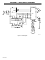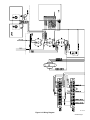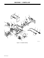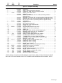
1
OM-867 083 696D December 1993 OWNER’S MANUAL Digi-Meter 1500 RMS (AC/DC) Digital Ammeter/Voltmeter For Measuring Weld Output Accurately (±1%) Measures DC Or AC (RMS) Output Max. Capacity: 1500 Amperes, 100 Volts AC/DC At 100% Duty Cycle Includes 8 ft (2.4 m) 115 Volts AC Input Power Cord Displays To Nearest Ampere And 1/10 Volt Has Hold Feature Which Takes Readings After 10 Seconds Of Welding And Holds Displays For 15 Seconds After Welding Stops Read and follow these instructions and all safety blocks carefully. Give this manual to the operator. Have only trained and qualified persons install, operate, or service this unit. For help, call your distributor Call your distributor if you do not understand the directions. or: MILLER Electric Mfg. Co., P.O. Box 1079, Appleton, WI 54912 414-734-9821 cover 7/93 – ST-084 121-A 1993 MILLER Electric Mfg. Co. PRINTED IN USA From Miller to You Thank you and congratulations on choosing Miller. Now you can get the job done and get it done right. We know you don’t have time to do it any other way. That’s why when Niels Miller first started building arc welders in 1929, he made sure his products offered long-lasting value and superior quality. Like you, his customers couldn’t afford anything less. Miller products had to be more than the best they could be. They had to be the best you could buy. Today, the people that build and sell Miller products continue the tradition. They’re just as committed to providing equipment and service that meets the high standards of quality and value established in 1929. This Owner’s Manual is designed to help you get the most out of your Miller products. Please take time to read the Safety precautions. They will help you protect yourself against potential hazards on the worksite. We’ve made installation and operation quick and easy. With Miller you can count on years of reliable service with proper maintenance. And if for some reason the unit needs repair, there’s a Troubleshooting section that will help you Miller is the first welding figure out what the problem is. The parts list equipment manufacturer in will then help you to decide which exact part the U.S.A. to be registered to the ISO 9001 Quality System you may need to fix the problem. Warranty and Standard. service information for your particular model are also provided. Miller Electric manufactures a full line of welders and welding related equipment. For information on other quality Miller products, contact your local Miller distributor to receive the latest full line catalog or individual catalog sheets. To locate your nearest distributor or service agency call 1-800-4-A-Miller, or visit us at www.MillerWelds.com on the web. Working as hard as you do – every power source from Miller is backed by the most hassle-free warranty in the business. Miller offers a Technical Manual which provides more detailed service and parts information for your unit. To obtain a Technical Manual, contact your local distributor. Your distributor can also supply you with Welding Process Manuals such as SMAW, GTAW, GMAW, and GMAW-P. ARC WELDING SAFETY PRECAUTIONS WARNING ARC WELDING can be hazardous. PROTECT YOURSELF AND OTHERS FROM POSSIBLE SERIOUS INJURY OR DEATH. KEEP CHILDREN AWAY. PACEMAKER WEARERS KEEP AWAY UNTIL CONSULTING YOUR DOCTOR. In welding, as in most jobs, exposure to certain hazards occurs. Welding is safe when precautions are taken. The safety information given below is only a summary of the more complete safety information that will be found in the Safety Standards listed on the next page. Read and follow all Safety Standards. HAVE ALL INSTALLATION, OPERATION, MAINTENANCE, AND REPAIR WORK PERFORMED ONLY BY QUALIFIED PEOPLE. in disconnect box or that cord plug is connected to a properly grounded receptacle outlet. ELECTRIC SHOCK can kill. Touching live electrical parts can cause fatal shocks or severe burns. The electrode and work circuit is electrically live whenever the output is on. The input power circuit and machine internal circuits are also live when power is on. In semiautomatic or automatic wire welding, the wire, wire reel, drive roll housing, and all metal parts touching the welding wire are electrically live. Incorrectly installed or improperly grounded equipment is a hazard. 1. Do not touch live electrical parts. 2. Wear dry, hole-free insulating gloves and body protection. 3. Insulate yourself from work and ground using dry insulating mats or covers big enough to prevent any physical contact with the work or ground. 4. Disconnect input power or stop engine before installing or servicing this equipment. Lockout/tagout input power according to OSHA 29 CFR 1910.147 (see Safety Standards). 5. Properly install and ground this equipment according to its Owner’s Manual and national, state, and local codes. 6. Always verify the supply ground – check and be sure that input power cord ground wire is properly connected to ground terminal ARC RAYS can burn eyes and skin; NOISE can damage hearing; FLYING SLAG OR SPARKS can injure eyes. Arc rays from the welding process produce intense visible and invisible (ultraviolet and infrared) rays that can burn eyes and skin. Noise from some processes can damage hearing. Chipping, grinding, and welds cooling throw off pieces of metal or slag. NOISE 1. Use approved ear plugs or ear muffs if noise level is high. FUMES AND GASES can be hazardous to your health. Welding produces fumes and gases. Breathing these fumes and gases can be hazardous to your health. 1. Keep your head out of the fumes. Do not breathe the fumes. 2. If inside, ventilate the area and/or use exhaust at the arc to remove welding fumes and gases. 3. If ventilation is poor, use an approved air-supplied respirator. 4. Read the Material Safety Data Sheets (MSDSs) and the manufacturer’s instruction for metals, consumables, coatings, cleaners, and degreasers. CYLINDERS can explode if damaged. Shielding gas cylinders contain gas under high pressure. If damaged, a cylinder can explode. Since gas cylinders are normally part of the welding process, be sure to treat them carefully. 1. Protect compressed gas cylinders from excessive heat, mechanical shocks, slag, open flames, sparks, and arcs. 2. Install cylinders in an upright position by securing to a stationary support or cylinder rack to prevent falling or tipping. 3. Keep cylinders away from any welding or other electrical circuits. 7. When making input connections, attach proper grounding conductor first – double-check connections. 8. Frequently inspect input power cord for damage or bare wiring – replace cord immediately if damaged – bare wiring can kill. 9. Turn off all equipment when not in use. 10. Do not use worn, damaged, undersized, or poorly spliced cables. 11. Do not drape cables over your body. 12. If earth grounding of the workpiece is required, ground it directly with a separate cable – do not use work clamp or work cable. 13. Do not touch electrode if you are in contact with the work, ground, or another electrode from a different machine. 14. Use only well-maintained equipment. Repair or replace damaged parts at once. Maintain unit according to manual. 15. Wear a safety harness if working above floor level. 16. Keep all panels and covers securely in place. 17. Clamp work cable with good metal-to-metal contact to workpiece or worktable as near the weld as practical. ARC RAYS 2. Wear a welding helmet fitted with a proper shade of filter to protect your face and eyes when welding or watching (see ANSI Z49.1 and Z87.1 listed in Safety Standards). 3. Wear approved safety glasses with side shields. 4. Use protective screens or barriers to protect others from flash and glare; warn others not to watch the arc. 5. Wear protective clothing made from durable, flame-resistant material (wool and leather) and foot protection. 5. Work in a confined space only if it is well ventilated, or while wearing an air-supplied respirator. Always have a trained watchperson nearby. Welding fumes and gases can displace air and lower the oxygen level causing injury or death. Be sure the breathing air is safe. 6. Do not weld in locations near degreasing, cleaning, or spraying operations. The heat and rays of the arc can react with vapors to form highly toxic and irritating gases. 7. Do not weld on coated metals, such as galvanized, lead, or cadmium plated steel, unless the coating is removed from the weld area, the area is well ventilated, and if necessary, while wearing an air-supplied respirator. The coatings and any metals containing these elements can give off toxic fumes if welded. 4. 5. 6. 7. Never drape a welding torch over a gas cylinder. Never allow a welding electrode to touch any cylinder. Never weld on a pressurized cylinder – explosion will result. Use only correct shielding gas cylinders, regulators, hoses, and fittings designed for the specific application; maintain them and associated parts in good condition. 8. Turn face away from valve outlet when opening cylinder valve. 9. Keep protective cap in place over valve except when cylinder is in use or connected for use. 10. Read and follow instructions on compressed gas cylinders, associated equipment, and CGA publication P-1 listed in Safety Standards. sr1.1.1 2/94 WELDING can cause fire or explosion. Welding on closed containers, such as tanks, drums, or pipes, can cause them to blow up. Sparks can fly off from the welding arc. The flying sparks, hot workpiece, and hot equipment can cause fires and burns. Accidental contact of electrode to metal objects can cause sparks, explosion, overheating, or fire. Check and be sure the area is safe before doing any welding. 1. Protect yourself and others from flying sparks and hot metal. 2. Do not weld where flying sparks can strike flammable material. 3. Remove all flammables within 35 ft (10.7 m) of the welding arc. If this is not possible, tightly cover them with approved covers. 4. Be alert that welding sparks and hot materials from welding can easily go through small cracks and openings to adjacent areas. 5. Watch for fire, and keep a fire extinguisher nearby. WARNING 6. Be aware that welding on a ceiling, floor, bulkhead, or partition can cause fire on the hidden side. 7. Do not weld on closed containers such as tanks, drums, or pipes, unless they are properly prepared according to AWS F4.1 (see Safety Standards). 8. Connect work cable to the work as close to the welding area as practical to prevent welding current from traveling long, possibly unknown paths and causing electric shock and fire hazards. 9. Do not use welder to thaw frozen pipes. 10. Remove stick electrode from holder or cut off welding wire at contact tip when not in use. 11. Wear oil-free protective garments such as leather gloves, heavy shirt, cuffless trousers, high shoes, and a cap. 12. Remove any combustibles, such as a butane lighter or matches, from your person before doing any welding. ENGINES can be hazardous. ENGINE EXHAUST GASES can kill. 1. Use equipment outside in open, well-ventilated areas. Engines produce harmful exhaust gases. 2. If used in a closed area, vent engine exhaust outside and away from any building air intakes. ENGINE FUEL can cause fire or explosion. 3. Do not overfill tank – allow room for fuel to expand. 4. Do not spill fuel. If fuel is spilled, clean up before starting engine. Engine fuel is highly flammable. 1. Stop engine and let it cool off before checking or adding fuel. 2. Do not add fuel while smoking or if unit is near any sparks or open flames. MOVING PARTS can cause injury. Moving parts, such as fans, rotors, and belts can cut fingers and hands and catch loose clothing. 1. Keep all doors, panels, covers, and guards closed and securely in place. 2. Stop engine before installing or connecting unit. SPARKS can cause BATTERY GASES TO EXPLODE; BATTERY ACID can burn eyes and skin. Batteries contain acid and generate explosive gases. STEAM AND PRESSURIZED HOT COOLANT can burn face, eyes, and skin. It is best to check coolant level when engine is cold to avoid scalding. 3. Have only qualified people remove guards or covers for maintenance and troubleshooting as necessary. 4. To prevent accidental starting during servicing, disconnect negative (–) battery cable from battery. 5. Keep hands, hair, loose clothing, and tools away from moving parts. 6. Reinstall panels or guards and close doors when servicing is finished and before starting engine. 1. Always wear a face shield when working on a battery. 2. Stop engine before disconnecting or connecting battery cables. 3. Do not allow tools to cause sparks when working on a battery. 4. Do not use welder to charge batteries or jump start vehicles. 5. Observe correct polarity (+ and –) on batteries. 1. If the engine is warm and checking is needed, follow steps 2 and 3. 2. Wear safety glasses and gloves and put a rag over cap. 3. Turn cap slightly and let pressure escape slowly before completely removing cap. PRINCIPAL SAFETY STANDARDS Safety in Welding and Cutting, ANSI Standard Z49.1, from American Welding Society, 550 N.W. LeJeune Rd, Miami FL 33126 Safety and Health Standards, OSHA 29 CFR 1910, from Superintendent of Documents, U.S. Government Printing Office, Washington, D.C. 20402. Recommended Safe Practices for the Preparation for Welding and Cutting of Containers That Have Held Hazardous Substances, American Welding Society Standard AWS F4.1, from American Welding Society, 550 N.W. LeJeune Rd, Miami, FL 33126 National Electrical Code, NFPA Standard 70, from National Fire Protection Association, Batterymarch Park, Quincy, MA 02269. sr1.1.1 2/94 Safe Handling of Compressed Gases in Cylinders, CGA Pamphlet P-1, from Compressed Gas Association, 1235 Jefferson Davis Highway, Suite 501, Arlington, VA 22202. Code for Safety in Welding and Cutting, CSA Standard W117.2, from Canadian Standards Association, Standards Sales, 178 Rexdale Boulevard, Rexdale, Ontario, Canada M9W 1R3. Safe Practices For Occupation And Educational Eye And Face Protection, ANSI Standard Z87.1, from American National Standards Institute, 1430 Broadway, New York, NY 10018. Cutting And Welding Processes, NFPA Standard 51B, from National Fire Protection Association, Batterymarch Park, Quincy, MA 02269. EMF INFORMATION NOTE Considerations About Welding And The Effects Of Low Frequency Electric And Magnetic Fields The following is a quotation from the General Conclusions Section of the U.S. Congress, Office of Technology Assessment, Biological Effects of Power Frequency Electric & Magnetic Fields – Background Paper, OTA-BP-E-53 (Washington, DC: U.S. Government Printing Office, May 1989): “. . . there is now a very large volume of scientific findings based on experiments at the cellular level and from studies with animals and people which clearly establish that low frequency magnetic fields can interact with, and produce changes in, biological systems. While most of this work is of very high quality, the results are complex. Current scientific understanding does not yet allow us to interpret the evidence in a single coherent framework. Even more frustrating, it does not yet allow us to draw definite conclusions about questions of possible risk or to offer clear science-based advice on strategies to minimize or avoid potential risks.” To reduce magnetic fields in the workplace, use the following procedures: 1. Keep cables close together by twisting or taping them. 2. Arrange cables to one side and away from the operator. 3. Do not coil or drape cables around the body. 4. Keep welding power source and cables as far away as practical. 5. Connect work clamp to workpiece as close to the weld as possible. About Pacemakers: The above procedures are among those also normally recommended for pacemaker wearers. Consult your doctor for complete information. mod10.1 4/93 TABLE OF CONTENTS SECTION 1 – SAFETY INFORMATION . . . . . . . . . . . . . . . . . . . . . . . . . . . . . . . . . . . . . . . . . . . . . . . . . . . . 1 SECTION 2 – SPECIFICATIONS . . . . . . . . . . . . . . . . . . . . . . . . . . . . . . . . . . . . . . . . . . . . . . . . . . . . . . . . . . 1 SECTION 3 – INSTALLATION 3-1. 3-2. Location . . . . . . . . . . . . . . . . . . . . . . . . . . . . . . . . . . . . . . . . . . . . . . . . . . . . . . . . . . . . . . . . . . . . . . Connection Diagram . . . . . . . . . . . . . . . . . . . . . . . . . . . . . . . . . . . . . . . . . . . . . . . . . . . . . . . . . . . 2 3 SECTION 4 – OPERATION . . . . . . . . . . . . . . . . . . . . . . . . . . . . . . . . . . . . . . . . . . . . . . . . . . . . . . . . . . . . . . . 4 SECTION 5 – MAINTENANCE & TROUBLESHOOTING 5-1. 5-2. Routine Maintenance . . . . . . . . . . . . . . . . . . . . . . . . . . . . . . . . . . . . . . . . . . . . . . . . . . . . . . . . . . . Troubleshooting . . . . . . . . . . . . . . . . . . . . . . . . . . . . . . . . . . . . . . . . . . . . . . . . . . . . . . . . . . . . . . . 5 5 SECTION 6 – ELECTRICAL DIAGRAMS . . . . . . . . . . . . . . . . . . . . . . . . . . . . . . . . . . . . . . . . . . . . . . . . . . . 6 SECTION 7 – PARTS LIST Figure 7-1. Complete Assembly . . . . . . . . . . . . . . . . . . . . . . . . . . . . . . . . . . . . . . . . . . . . . . . . . . . . . . . . 8 OM-867D – 12/93 SECTION 1 – SAFETY INFORMATION mod1.1 2/93 Read all safety messages throughout this manual. Obey all safety messages to avoid injury. Learn the meaning of WARNING and CAUTION. 1 2 2 WARNING 3 • Do not touch live electrical parts. • Disconnect input power before MOVING PARTS can injure. • Keep away from moving parts. • Keep all panels and covers closed 4 installing or servicing. Safety Alert Symbol 2 Signal Word WARNING means possible death or serious injury can happen. CAUTION ELECTRIC SHOCK can kill. 1 when operating. CAUTION means possible minor injury or equipment damage can happen. 3 Statement Of Hazard And Result 4 Safety Instructions To Avoid Hazard 5 Hazard Symbol (If Available) 6 Safety Banner 5 6 READ SAFETY BLOCKS at start of Section 3-1 before proceeding. WARNING Read safety blocks for each symbol shown. 7 7 NOTE NOTE Special instructions for best operation – not related to safety. Turn Off switch when using high frequency. Figure 1-1. Safety Information SECTION 2 – SPECIFICATIONS Table 2-1. Meter Specifications Specification Description Type Of Input Power 115 Volts AC, 50/60 Hz Input Power Cord With Plug 8 ft (2.4 m) Voltage Sensing Cord With Clamp 21 ft (6.4 m) Overall Dimensions See Figure 3-1 Weight Net: 13.5 lb (6.1 kg); Ship: 15 lb (7 kg) Max. Capacity At 100% Duty Cycle 1500 Amps At 100 Volts AC/DC OM-867 Page 1 SECTION 3 – INSTALLATION WARNING ELECTRIC SHOCK can kill. • • Do not touch live electrical parts. Turn Off welding power source and disconnect input power before inspecting or installing. Stop engine on welding generator. FUMES can be hazardous; LACK OF F RESH AI R AND PRO PER VENTILATION can be harmful. • • Do not breathe welding fumes. Place unit only where there is a good fresh air supply and proper ventilation. swarn11.1* 3/93 3-1. Location Turn Off welding power source. 1 Inches Millimeters A 6 152 B 11-5/8 295 C 8-3/8 213 Meter Place meter on bench, welding power source, or other convenient location. 1 A B C ST-084 121-A Figure 3-1. Overall Dimensions OM-867 Page 2 3-2. Connection Diagram READ SAFETY BLOCKS at start of Section 3 before proceeding. WARNING Using meter in applications where high-frequency output is used may cause poor arc starting and unreliable meter readings. 1 Welding Power Source 2 Weld Cable (Customer Supplied) See power source Owner’s Manual for proper size cable. Keep cable length between meter and arc as short as possible for more accurate readings. 3 2 Meter 4 Access Door 5 Shunt Terminal 6 SMAW Electrode Holder 7 GTAW Torch 8 Wire Feeder Open access door and connect weld cable from power source to either shunt terminal. Connect weld cable from electrode holder, torch or wire feeder to other shunt terminal. 1 2 4 Close access door. 9 OR 115 VAC Cord/Plug 10 115 VAC Grounded Receptacle Connect input power plug to welding power source or other 115 VAC receptacle. 3 11 Voltage Sensing Cord/Clamp 8 12 Workpiece 6 Connect voltage sensing clamp to workpiece. 7 4 2 10 12 5 11 9 ST-154 610-B / ST-155 327 Figure 3-2. Connection Diagram OM-867 Page 3 SECTION 4 – OPERATION WARNING ELECTRIC SHOCK can kill. • • • • ARC RAYS can burn eyes and skin; NOISE can damage hearing. Always wear dry insulating gloves. Insulate yourself from work and ground. Do not touch live electrical parts. Keep all panels and covers securely in place. • • MOVING PARTS can cause injury. FUMES AND GASES can be hazardous to your health. • • • • • Keep your head out of the fumes. Ventilate area, or use breathing device. Read Material Safety Data Sheets (MSDSs) and manufacturer’s instructions for material used. • • Do not weld near flammable material. Watch for fire; keep extinguisher nearby. Do not locate unit over combustible surfaces. Do not weld on closed containers. Allow work and equipment to cool before handling. 1 2 Keep away from moving parts. Keep all doors, panels, covers, and guards closed and securely in place. MAGNETIC FIELDS FROM HIGH CURRENTS can affect pacemaker operation. WELDING can cause fire or explosion. • • • • • Wear welding helmet with correct shade of filter. Wear correct eye, ear, and body protection. Pacemaker wearers keep away. Wearers should consult their doctor before going near arc welding, gouging, or spot welding operations. See Safety Precautions at beginning of manual for basic welding safety information. swarn6.1 10/91 3 1 Insulating Gloves 2 Safety Glasses With Side Shields 3 Welding Helmet Wear dry insulating gloves, safety glasses with side shields, and a welding helmet with a correct shade of filter (see ANSI Z49.1). sb3.1 10/91 Figure 4-1. Safety Equipment 1 1 Voltmeter Displays to nearest 1/10 volt. 3 VOLTS 2 Ammeter Displays to nearest ampere. HOLD 2 3 Std./Hold Switch Use switch to select meters display function. STD. AMPS In Std. (Standard) position, meters continuously display actual volts/ amps while welding; preset value while idling. Example: STD. HOLD STD. OCV 60.0 50.0 OCV 60.0 000 100 000 Idling Value Start Welding Displays New Value Stop Welding Clears Value In Hold position, meters measure volts/amps after 10 seconds of welding and holds values on displays for 15 seconds after welding stops. Hold function does not work when welding amperage is less than 60 A. HOLD OCV 60.0 HOLD 000 STD. Idling Value Start Welding After 10 Seconds 50.0 50.0 OCV 60.0 100 100 000 Displays New Value Stop Welding For 15 Holds Value Seconds Clears Value ST-154 616 Figure 4-2. Voltmeter/Ammeter And Std./Hold Switch OM-867 Page 4 SECTION 5 – MAINTENANCE & TROUBLESHOOTING WARNING ELECTRIC SHOCK can kill. • • HOT PARTS can cause severe burns. Do not touch live electrical parts. • Turn Off welding power source, and disconnect input power before inspecting, maintaining, or servicing. Stop engine on welding generator. Maintenance and troubleshooting to be performed only by qualified persons. Allow cooling period before maintaining or servicing. swarn8.1* 10/91 5-1. Routine Maintenance 3 Months Turn Off all power before maintaining. 6 Months Replace Unreadable Labels See Section 7 OR –– –– Tape Or Replace Cracked Weld Cable 3-2 Clean And Tighten Weld Terminals Blow Out Or Vacuum Inside ST-084 121-A Figure 5-1. Maintenance Schedule 5-2. Troubleshooting WARNING READ SAFETY BLOCKS at start of Section 5 before proceeding. Table 5-1. Welding Trouble Trouble Remedy Section Unit completely inoperative; no meter display. Be sure input power cord is plugged in and that receptacle is receiving input power. 3-2 Incorrect meter display. Check weld cable, input power, and voltage sensing connections. 3-2 Turn off high frequency, if applicable. 3-2 Check connections to meter module; tighten or clean if necessary. –– Check and replace meter module if necessary. –– Have Factory Authorized Service Station/Service Distributor check digital meter board PC1. –– Erratic meter display. Check connections to meter shunt; tighten or clean if necessary. –– Meters do not hold display with Std./Hold switch in Hold position. Place switch in Std. position when welding amperage is below required minimum. Figure 4-2 Have Factory Authorized Service Station/Service Distributor check digital meter board PC1. –– No display on one meter only; other meter works. OM-867 Page 5 SECTION 6 – ELECTRICAL DIAGRAMS SB-131 649 Figure 6-1. Circuit Diagram OM-867 Page 6 SC-132 589 Figure 6-2. Wiring Diagram OM-867 Page 7 SECTION 7 – PARTS LIST 1 2 7 6 5 4 29 30 3 31 28 8 9 10 29 13 14 15 16 18 25 26 27 12 11 24 19 23 28 17 20 21 22 ST-083 851-D Figure 7-1. Complete Assembly OM-867 Page 8 Item No. Dia. Mkgs. Part No. Description Quantity Figure 7-1. Complete Assembly . . . 1 . . . . . . . . . . . . . . +082 980 . . . 2 . . . . . . . . . . . . . . . . 134 327 . . . 3 . . . . . . . . . . . . . . . . 025 248 . . . 4 . . . . . Shunt . . . . . 072 425 . . . 5 . . . . . . . . . . . . . . . . 083 082 . . . . . . . . . . . . . . . . . . . . . . 604 126 . . . WRAPPER . . . . . . . . . . . . . . . . . . . . . . . . . . . . . . . . . . . . . . . . . . . . . . . . . . . 1 . . . LABEL, warning general precautionary . . . . . . . . . . . . . . . . . . . . . . . . . . . 1 . . . STAND-OFF, insul .250-20 x 1.250 lg x .437thk . . . . . . . . . . . . . . . . . . . 4 . . . SHUNT, meter 50MV 1500A . . . . . . . . . . . . . . . . . . . . . . . . . . . . . . . . . . . . 1 . . . BUS BAR, jumper . . . . . . . . . . . . . . . . . . . . . . . . . . . . . . . . . . . . . . . . . . . . . 2 . . . SCREW, cap stl hexhd .500-13 x 1.000 (connecting cables to digimeter shunt) . . . . . . . . . . . . . . . . . . . . . . . . . . . . . . . . . . . . . . . . . . . . . . . 2 . . . . . . . . . . . . . . . . . . . . . . 602 216 . . . WASHER, lock stl split .500 (connecting cables to digimeter shunt) . . 2 . . . . . . . . . . . . . . . . . . . . . . 602 247 . . . WASHER, flat stl SAE .500 (connecting cables to digimeter shunt) . . . 2 . . . . . . . . . . . . . . . . . . . . . . 601 879 . . . NUT, stl hex full .500-13 (connecting cables to digimeter shunt) . . . . . . 2 . . . 6 . . . . C53,54 . . . . 143 461 . . . CAPACITOR . . . . . . . . . . . . . . . . . . . . . . . . . . . . . . . . . . . . . . . . . . . . . . . . . 2 . . . 7 . . . . . . . . . . . . . . . . 082 983 . . . WRAPPER, shunt . . . . . . . . . . . . . . . . . . . . . . . . . . . . . . . . . . . . . . . . . . . . . 1 . . . 8 . . . . . . . . . . . . . . . . 600 848 . . . WIRE, lead mot 12ga strd . . . . . . . . . . . . . . . . . . . . . . . . . . . . . . . . . . . . . 21ft . . . 9 . . . . . . . . . . . . . . . . 601 226 . . . INSULATOR, vinyl clamp univ 25A . . . . . . . . . . . . . . . . . . . . . . . . . . . . . . 1 . . . 10 . . . . . . . . . . . . . . . . 601 228 . . . CLAMP, univ 25A . . . . . . . . . . . . . . . . . . . . . . . . . . . . . . . . . . . . . . . . . . . . . 1 . . . 11 . . . . PLG50 . . . . 073 690 . . . PLUG, str grd armd 2P3W 15A 125V . . . . . . . . . . . . . . . . . . . . . . . . . . . . 1 . . . 12 . . . . . . . . . . . . . . . . 604 825 . . . CABLE, port No. 18 3/c (order by ft) . . . . . . . . . . . . . . . . . . . . . . . . . . . . . 8ft . . . 13 . . . . . . . . . . . . . . . . 131 708 . . . PANEL, rear . . . . . . . . . . . . . . . . . . . . . . . . . . . . . . . . . . . . . . . . . . . . . . . . . . 1 . . . 14 . . . . . . . . . . . . . . . . 603 107 . . . HOSE, nprn slit bk .156 ID x .343 OD (order by ft) . . . . . . . . . . . . . . . . . 1ft . . . 15 . . . . . . . . . . . . . . . . 010 476 . . . BUSHING, strain relief .625 ID x .570mtg hole . . . . . . . . . . . . . . . . . . . . 1 . . . 16 . . . . . . . . . . . . . . . . 131 709 . . . CASE SECTION, bottom/front . . . . . . . . . . . . . . . . . . . . . . . . . . . . . . . . . . 1 . . . 17 . . . . . PC1 . . . . . 132 299 . . . CIRCUIT CARD, digital meter AC/DC models . . . . . . . . . . . . . . . . . . . . . 1 . . . . . . . . . . . PLG1 . . . . . 135 559 . . . CONNECTOR & SOCKETS, (consisting of) . . . . . . . . . . . . . . . . . . . . . . 1 . . . . . . . . . . . . . . . . . . . . . . 079 747 . . . . CONNECTOR, rect skt 24-18ga Amp 350980-1 . . . . . . . . . . . . . . . . . 12 . . . 18 . . . . . . . . . . . . . . . . 080 509 . . . GROMMET, scr No. 8/10 panel hole .312sq .375 high . . . . . . . . . . . . . . 2 . . . 19 . . . . . . . . . . . . . . . . 131 762 . . . BRACKET, mtg PC card . . . . . . . . . . . . . . . . . . . . . . . . . . . . . . . . . . . . . . . 1 . . . 20 . . . . . FL1-3 . . . . . 084 171 . . . FILTER, line pwr 115/250V 50-400Hz at 2A . . . . . . . . . . . . . . . . . . . . . . . 3 . . . 21 . . . . . . . . . . . . . . . . 132 124 . . . STAND-OFF, 6-32 x 1.000 lg . . . . . . . . . . . . . . . . . . . . . . . . . . . . . . . . . . . 2 . . . 22 . . . . . . . . . . . . . . . . 094 484 . . . STAND-OFF, 6-32 x 1.000 lg . . . . . . . . . . . . . . . . . . . . . . . . . . . . . . . . . . . 2 . . . 23 . . . . . . . . . . . . . . . . 019 663 . . . MOUNT, nprn 15/16 OD . . . . . . . . . . . . . . . . . . . . . . . . . . . . . . . . . . . . . . . . 4 . . . 24 . . . . . . . . . . . . . . . . . . . . . . . . . . . NAMEPLATE, (order by model and style number) . . . . . . . . . . . . . . . . . 1 . . . 25 . . . . C50,51 . . . . 122 723 . . . CAPACITOR, cer mono .1uf 50VDC . . . . . . . . . . . . . . . . . . . . . . . . . . . . . 2 . . . 26 . . . . . D1,2 . . . . . 026 202 . . . DIODE, rect 1A 400V SP . . . . . . . . . . . . . . . . . . . . . . . . . . . . . . . . . . . . . . . 2 . . . 27 . . . . PLG2,3 . . . . 028 598 . . . CONNECTOR, edge 15skt plug Amp 582772-3 . . . . . . . . . . . . . . . . . . . 2 . . . 28 . . . . . Amp . . . . . 083 722 . . . METER, digital 0 to 19.99V . . . . . . . . . . . . . . . . . . . . . . . . . . . . . . . . . . . . . 1 . . . 29 . . . . . Volt . . . . . . 081 798 . . . METER, digital 0 to 19.99V LED 115VAC . . . . . . . . . . . . . . . . . . . . . . . . . 1 . . . 30 . . . . . T50 . . . . . . 131 685 . . . TRANSFORMER, control . . . . . . . . . . . . . . . . . . . . . . . . . . . . . . . . . . . . . . 1 . . . 31 . . . . . S50 . . . . . . 011 609 . . . SWITCH, tgl SPDT 15A 125VAC . . . . . . . . . . . . . . . . . . . . . . . . . . . . . . . . 1 +When ordering a component originally displaying a precautionary label, the label should also be ordered. BE SURE TO PROVIDE MODEL AND STYLE NUMBER WHEN ORDERING REPLACEMENT PARTS. OM-867 Page 9 Notes OM-867 Page 10 Notes OM-867 Page 11 Notes OM-867 Page 12 Effective January 1, 2000 (Equipment with a serial number preface of “LA” or newer) This limited warranty supersedes all previous Miller warranties and is exclusive with no other guarantees or warranties expressed or implied. Warranty Questions? Call 1-800-4-A-MILLER for your local Miller distributor. Your distributor also gives you ... Service You always get the fast, reliable response you need. Most replacement parts can be in your hands in 24 hours. Support Need fast answers to the tough welding questions? Contact your distributor. The expertise of the distributor and Miller is there to help you, every step of the way. * LIMITED WARRANTY – Subject to the terms and conditions below, Miller Electric Mfg. Co., Appleton, Wisconsin, warrants to its original retail purchaser that new Miller equipment sold after the effective date of this limited warranty is free of defects in material and workmanship at the time it is shipped by Miller. THIS WARRANTY IS EXPRESSLY IN LIEU OF ALL OTHER WARRANTIES, EXPRESS OR IMPLIED, INCLUDING THE WARRANTIES OF MERCHANTABILITY AND FITNESS. Within the warranty periods listed below, Miller will repair or replace any warranted parts or components that fail due to such defects in material or workmanship. Miller must be notified in writing within thirty (30) days of such defect or failure, at which time Miller will provide instructions on the warranty claim procedures to be followed. Miller shall honor warranty claims on warranted equipment listed below in the event of such a failure within the warranty time periods. All warranty time periods start on the date that the equipment was delivered to the original retail purchaser, or one year after the equipment is sent to a North American distributor or eighteen months after the equipment is sent to an International distributor. 1. 5 Years Parts – 3 Years Labor * * 2. 3 Years — Parts and Labor * * * * * * 3. Original main power rectifiers Inverters (input and output rectifiers only) Transformer/Rectifier Power Sources Plasma Arc Cutting Power Sources Semi-Automatic and Automatic Wire Feeders Inverter Power Supplies Intellitig Engine Driven Welding Generators (NOTE: Engines are warranted separately by the engine manufacturer.) 1 Year — Parts and Labor * * * * * * * * * * * * * * * * * DS-2 Wire Feeder Motor Driven Guns (w/exception of Spoolmate 185 & Spoolmate 250) Process Controllers Positioners and Controllers Automatic Motion Devices RFCS Foot Controls Induction Heating Power Sources Water Coolant Systems HF Units Grids Maxstar 140 Spot Welders Load Banks Miller Cyclomatic Equipment Running Gear/Trailers Plasma Cutting Torches (except APT & SAF Models) Field Options (NOTE: Field options are covered under True Blue for the remaining warranty period of the product they are installed in, or for a minimum of one year — whichever is greater.) 4. 6 Months — Batteries 5. 90 Days — Parts * * MIG Guns/TIG Torches Induction Heating Coils and Blankets * * * * * APT, ZIPCUT & PLAZCUT Model Plasma Cutting Torches Remote Controls Accessory Kits Replacement Parts (No labor) Spoolmate 185 & Spoolmate 250 Canvas Covers Miller’s True Blue Limited Warranty shall not apply to: 1. Consumable components; such as contact tips, cutting nozzles, contactors, brushes, slip rings, relays or parts that fail due to normal wear. 2. Items furnished by Miller, but manufactured by others, such as engines or trade accessories. These items are covered by the manufacturer’s warranty, if any. 3. Equipment that has been modified by any party other than Miller, or equipment that has been improperly installed, improperly operated or misused based upon industry standards, or equipment which has not had reasonable and necessary maintenance, or equipment which has been used for operation outside of the specifications for the equipment. MILLER PRODUCTS ARE INTENDED FOR PURCHASE AND USE BY COMMERCIAL/INDUSTRIAL USERS AND PERSONS TRAINED AND EXPERIENCED IN THE USE AND MAINTENANCE OF WELDING EQUIPMENT. In the event of a warranty claim covered by this warranty, the exclusive remedies shall be, at Miller’s option: (1) repair; or (2) replacement; or, where authorized in writing by Miller in appropriate cases, (3) the reasonable cost of repair or replacement at an authorized Miller service station; or (4) payment of or credit for the purchase price (less reasonable depreciation based upon actual use) upon return of the goods at customer’s risk and expense. Miller’s option of repair or replacement will be F.O.B., Factory at Appleton, Wisconsin, or F.O.B. at a Miller authorized service facility as determined by Miller. Therefore no compensation or reimbursement for transportation costs of any kind will be allowed. TO THE EXTENT PERMITTED BY LAW, THE REMEDIES PROVIDED HEREIN ARE THE SOLE AND EXCLUSIVE REMEDIES. IN NO EVENT SHALL MILLER BE LIABLE FOR DIRECT, INDIRECT, SPECIAL, INCIDENTAL OR CONSEQUENTIAL DAMAGES (INCLUDING LOSS OF PROFIT), WHETHER BASED ON CONTRACT, TORT OR ANY OTHER LEGAL THEORY. ANY EXPRESS WARRANTY NOT PROVIDED HEREIN AND ANY IMPLIED WARRANTY, GUARANTY OR REPRESENTATION AS TO PERFORMANCE, AND ANY REMEDY FOR BREACH OF CONTRACT TORT OR ANY OTHER LEGAL THEORY WHICH, BUT FOR THIS PROVISION, MIGHT ARISE BY IMPLICATION, OPERATION OF LAW, CUSTOM OF TRADE OR COURSE OF DEALING, INCLUDING ANY IMPLIED WARRANTY OF MERCHANTABILITY OR FITNESS FOR PARTICULAR PURPOSE, WITH RESPECT TO ANY AND ALL EQUIPMENT FURNISHED BY MILLER IS EXCLUDED AND DISCLAIMED BY MILLER. Some states in the U.S.A. do not allow limitations of how long an implied warranty lasts, or the exclusion of incidental, indirect, special or consequential damages, so the above limitation or exclusion may not apply to you. This warranty provides specific legal rights, and other rights may be available, but may vary from state to state. In Canada, legislation in some provinces provides for certain additional warranties or remedies other than as stated herein, and to the extent that they may not be waived, the limitations and exclusions set out above may not apply. This Limited Warranty provides specific legal rights, and other rights may be available, but may vary from province to province. miller_warr 7/00 Owner’s Record Please complete and retain with your personal records. Model Name Serial/Style Number Purchase Date (Date which equipment was delivered to original customer.) Distributor Address City State Zip For Service Call 1-800-4-A-Miller or see our website at www.MillerWelds.com to locate a DISTRIBUTOR or SERVICE AGENCY near you. Always provide Model Name and Serial/Style Number. Contact your Distributor for: Welding Supplies and Consumables Options and Accessories Personal Safety Equipment Service and Repair Miller Electric Mfg. Co. An Illinois Tool Works Company 1635 West Spencer Street Appleton, WI 54914 USA Replacement Parts Training (Schools, Videos, Books) International Headquarters–USA USA Phone: 920-735-4505 Auto-Attended USA & Canada FAX: 920-735-4134 International FAX: 920-735-4125 Technical Manuals (Servicing Information and Parts) Circuit Diagrams European Headquarters – United Kingdom Phone: 44 (0) 1204-593493 FAX: 44 (0) 1204-598066 Welding Process Handbooks www.MillerWelds.com Contact the Delivering Carrier for: File a claim for loss or damage during shipment. For assistance in filing or settling claims, contact your distributor and/or equipment manufacturer’s Transportation Department. PRINTED IN USA 2000 Miller Electric Mfg. Co. 6/00