1
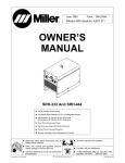
May 1992
Form: OM-867C
Effective With Style No. KA26
Model(s): DIGI-METER 600
DIGI-METER 1500
DIGI-METER 1500 AC/DC
OWNER’S MANUAL
IMPORTANT: Read and understand the entire contents of both this manual and
the power source manual used with this unit, with special emphasis on the safety MILLER ELECTRIC Mfg. Co.
material throughout the manual, before installing, operating, or maintaining this A Miller Group Ltd., Company
equipment. This unit and these instructions are for use only by persons trained P.O. Box 1079
and experienced in the safe operation of welding equipment. Do not allow Appleton, WI 54912 USA
untrained persons to install, operate, or maintain this unit. Contact your distributor Tel. 414-734-9821
if you do not fully understand these instructions.
cover2 4/92 − ST-084 121-A
PRINTED IN USA
TABLE OF CONTENTS
SECTION 1 − SAFETY SIGNAL WORDS . . . . . . . . . . . . . . . . . . . . . . . . . . . . . . . . . . . . . . . . . . . . . . . . . .
1
SECTION 2 − SPECIFICATIONS . . . . . . . . . . . . . . . . . . . . . . . . . . . . . . . . . . . . . . . . . . . . . . . . . . . . . . . . . .
1
SECTION 3 − INSTALLATION
3-1.
Location . . . . . . . . . . . . . . . . . . . . . . . . . . . . . . . . . . . . . . . . . . . . . . . . . . . . . . . . . . . . . . . . . . . . . .
3-2.
Connection Diagram . . . . . . . . . . . . . . . . . . . . . . . . . . . . . . . . . . . . . . . . . . . . . . . . . . . . . . . . . . .
2
2
SECTION 4 − OPERATION . . . . . . . . . . . . . . . . . . . . . . . . . . . . . . . . . . . . . . . . . . . . . . . . . . . . . . . . . . . . . . .
3
SECTION 5 − MAINTENANCE & TROUBLESHOOTING
5-1.
Routine Maintenance . . . . . . . . . . . . . . . . . . . . . . . . . . . . . . . . . . . . . . . . . . . . . . . . . . . . . . . . . . .
5-2.
Troubleshooting . . . . . . . . . . . . . . . . . . . . . . . . . . . . . . . . . . . . . . . . . . . . . . . . . . . . . . . . . . . . . . .
4
4
SECTION 6 − ELECTRICAL DIAGRAMS . . . . . . . . . . . . . . . . . . . . . . . . . . . . . . . . . . . . . . . . . . . . . . . . . . .
5
SECTION 7 − PARTS LIST
Figure 7-1. Complete Assembly (Digi-Meter 1500 Model Illustrated) . . . . . . . . . . . . . . . . . . . . . . . . .
8
OM-867C − 5/92
SECTION 1 − SAFETY SIGNAL WORDS
mod1.1 9/91
The following safety alert symbol and signal words are used throughout this manual to call attention to and identify
different levels of hazard and special instructions.
WARNING
WARNING statements identify procedures or practices which must be followed to avoid serious personal
injury or loss of life.
CAUTION
CAUTION statements identify procedures or practices which must be followed to avoid minor personal
injury or damage to this equipment.
IMPORTANT: statements identify special instructions necessary for the most efficient operation of this equipment.
SECTION 2 − SPECIFICATIONS
Table 2-1. Meter Specifications
Specification
Description
Type Of Input Power
115 Volts AC, 50/60 Hz, 0.5 Ampere
Input Power Cord With Plug
8 ft. (2.4 m)
Overall Dimensions
See Figure 3-1
600
1500
1500 AC/DC
Weight
Net: 11 lbs. (5 kg);
Ship: 12.5 lbs. (5.7 kg)
Net: 11 lbs. (5 kg);
Ship: 12.5 lbs. (5.7 kg)
Net: 13.5 lbs. (6.1 kg);
Ship: 15 lbs. (7 kg)
Max. Capacity At 100% Duty Cycle
600 Amps At 100 Volts DC
1500 Amps At 100 Volts DC
1500 Amps At 100 Volts AC/DC
SECTION 3 − INSTALLATION
WARNING
ELECTRIC SHOCK can kill.
•
•
Do not touch live electrical parts.
Turn OFF welding power source and disconnect
input power before inspecting or installing. Stop
engine on welding generator.
FUMES can be hazardous; LACK OF
FRESH
AIR
AND
PROPER
VENTILATION can be harmful.
•
•
Do not breathe welding fumes.
Place unit only where there is a good fresh air supply
and proper ventilation.
swarn11.1* 2/92
OM-867 Page 1
3-1. Location
Turn OFF welding power source.
1
1
Meter
Place meter on bench, welding
power source, or other convenient
location.
A
B
C
Inches
Millimeters
A
6
152
B
11-5/8
295
C
8-3/8
213
ST-084 121-A
Figure 3-1. Overall Dimensions
3-2. Connection Diagram
READ SAFETY BLOCKS at start of
Section 3 before proceeding.
WARNING
1
CC/CV Welding Power
Source
2
Weld Cable (Customer
Supplied)
See power source Owner’s Manual
for proper size cable. Keep cable
length between meter and arc as
short as possible for more accurate
readings.
2
11
1
10
2
4
3
Meter
4
Access Door
5
Shunt Terminal
6
Electrode Holder
7
Wire Feeder
Open access door and connect
weld cable from power source to either shunt terminal. Connect weld
cable from electrode holder or wire
feeder to other shunt terminal.
8
Close access door.
3
6
7
8
115 VAC Cord/Plug
9
115 VAC Grounded Receptacle
Connect input power plug to welding power source or other 115 VAC
receptacle.
4
2
10 Voltage Sensing Cord/Clamp
11 Workpiece
9
5
10
Connect voltage sensing clamp to
workpiece.
8
ST-154 610 / ST-155 327
Figure 3-2. Connection Diagram
OM-867 Page 2
SECTION 4 − OPERATION
WARNING
ELECTRIC SHOCK can kill.
•
•
•
•
ARC RAYS can burn eyes and skin;
NOISE can damage hearing.
Always wear dry insulating gloves.
Insulate yourself from work and ground.
Do not touch live electrical parts.
Keep all panels and covers securely in place.
•
•
MOVING PARTS can cause injury.
FUMES AND GASES can be hazardous
to your health.
•
•
•
•
•
Keep your head out of the fumes.
Ventilate area, or use breathing device.
Read Material Safety Data Sheets (MSDSs) and
manufacturer’s instructions for material used.
•
•
Do not weld near flammable material.
Watch for fire; keep extinguisher nearby.
Do not locate unit over combustible surfaces.
Do not weld on closed containers.
Allow work and equipment to cool before handling.
1
2
Keep away from moving parts.
Keep all doors, panels, covers, and guards closed
and securely in place.
MAGNETIC FIELDS FROM HIGH CURRENTS can affect pacemaker operation.
WELDING can cause fire or explosion.
•
•
•
•
•
Wear welding helmet with correct shade of filter.
Wear correct eye, ear, and body protection.
Pacemaker wearers keep away.
Wearers should consult their doctor before going
near arc welding, gouging, or spot welding operations.
See Safety Precautions at beginning of manual for basic welding safety information.
swarn6.1 10/91
3
1
Insulating Gloves
2
Safety Glasses With Side
Shields
3 Welding Helmet
Wear dry insulating gloves, safety
glasses with side shields, and a
welding helmet with a correct shade
of filter (see ANSI Z49.1).
sb3.1 10/91
Figure 4-1. Safety Equipment
1 Voltmeter
Displays voltage to nearest 1/10
volt.
1
3
VOLTS
2 Ammeter
Displays amperage to nearest ampere.
HOLD
2
STD.
3 Std./Hold Switch
Use switch to select meters display
function.
AMPS
Example:
HOLD
STD.
STD.
OCV
60.0
50.0
OCV
60.0
000
100
000
Idling Value
Start Welding
Displays New Value Stop Welding
Clears Value
HOLD
HOLD
OCV
60.0
50.0
000
STD.
Idling Value
Start Welding
100
After
10 Seconds Displays New Value Stop Welding
In Std. (Standard) position, meter
continuously displays actual volts/
amps while welding; preset value
while idling.
In Hold position, meter measures
volts/amps after 10 sec. of welding
and holds values on displays for 15
sec. after welding stops.
Hold function does not work when
welding amperage is less than 25A
when using 600 model or 60A when
using 1500 model.
50.0
OCV
60.0
100
000
For
Holds Value 15 Seconds Clears Value
ST-154 616
Figure 4-2. Voltmeter/Ammeter And Std./Hold Switch
OM-867 Page 3
SECTION 5 − MAINTENANCE & TROUBLESHOOTING
WARNING
ELECTRIC SHOCK can kill.
•
•
Do not touch live electrical parts.
Turn OFF welding power source, and disconnect
input power before inspecting, maintaining, or
servicing. Stop engine on welding generator.
HOT PARTS can cause severe burns.
•
Allow cooling period before maintaining or servicing.
Maintenance and troubleshooting to be performed only
by qualified persons.
swarn8.1* 10/91
5-1. Routine Maintenance
Table 5-1. Routine Maintenance
Time
Maintenance
Every month
Normal use: none.
More than normal equipment use: Repair any damaged weld cable insulation. Clean and tighten cable connections.
Every 3 months
Repair any damaged insulation or replace weld cables if necessary. Clean and tighten cable connections.
Every 6 months
Replace any labels that are unreadable or damaged (see Section 7 for part number). Remove unit outer
enclosure to blow out or vacuum dust and dirt inside using a clean, dry airstream or vacuum suction.
5-2. Troubleshooting
WARNING
READ SAFETY BLOCKS at start of
Section 5 before proceeding.
Table 5-2. Welding Trouble
Trouble
Remedy
Section
Unit completely inoperative; no meter
display.
Be sure input power cord is plugged in and that receptacle is receiving input power.
3-2
Incorrect meter display.
Check weld cable, input power, and voltage sensing connections.
3-2
No display on one meter only; other meter works.
Check connections to meter module; tighten or clean if necessary.
−−
Check and replace meter module if necessary.
−−
Have Factory Authorized Service Station check Digital Meter
Board PC1.
−−
Erratic meter display.
Check connections to meter shunt; tighten or clean if necessary.
−−
Meters do not hold display with STD./
HOLD switch in HOLD position.
Place switch S50 in STD. position when welding amperage is below
required minimum.
Figure 4-2
Have Factory Authorized Service Station check Digital Meter
Board PC1.
−−
OM-867 Page 4
SECTION 6 − ELECTRICAL DIAGRAMS
SB-131 649
Figure 6-1. Circuit Diagram
OM-867 Page 5
OM-867 Page 6
Figure 6-2. Wiring Diagram
SC-132 589
NOTES
OM-867 Page 7
SECTION 7 − PARTS LIST
1
7
2
6
5
4
3
30
31
29
28
8
9
10
29
13
16
27
28
26
15
14
17
18
25
12
11
24
19
23
20
21
22
ST-083 851-D
Figure 7-1. Complete Assembly (Digi-Meter 1500 Model Illustrated)
OM-867 Page 8
Quantity
Item
No.
Dia.
Mkgs.
Part
No.
Description
Model
600
1500
Figure 7-1. Complete Assembly
. . . 1 . . . . . . . . . +082 980 . . WRAPPER . . . . . . . . . . . . . . . . . . . . . . . . . . . . . . . . . . . . . . . . . . . . . . . . . 1 . . . . 1
. . . 2 . . . . . . . . . . 134 327 . . LABEL, warning general precautionary . . . . . . . . . . . . . . . . . . . . . . . . . . 1 . . . . 1
. . . 3 . . . . . . . . . . 025 248 . . STAND-OFF, insul .250-20 x 1.250 lg x .437thk . . . . . . . . . . . . . . . . . . . . . . . . . 4
. . . 4 . . Shunt . 030 084 . . SHUNT, meter 50MV 600A . . . . . . . . . . . . . . . . . . . . . . . . . . . . . . . . . . . . 1
. . . 4 . . Shunt . 072 425 . . SHUNT, meter 50MV 1500A . . . . . . . . . . . . . . . . . . . . . . . . . . . . . . . . . . . . . . . . . . 1
. . . 5 . . . . . . . . . . 082 198 . . BUS BAR, jumper . . . . . . . . . . . . . . . . . . . . . . . . . . . . . . . . . . . . . . . . . . . . 2
. . . 5 . . . . . . . . . . 083 082 . . BUS BAR, jumper . . . . . . . . . . . . . . . . . . . . . . . . . . . . . . . . . . . . . . . . . . . . . . . . . . . 2
. . . . . . . . . . . . . . . . 604 126 . . SCREW, cap stl hexhd .500-13 x 1.000 (connecting cables to
. . . . . . . . . . . . . . . . . . . . . . . . . . . digimeter shunt) . . . . . . . . . . . . . . . . . . . . . . . . . . . . . . . . . . . . . . . . . . . . . 2 . . . . 2
. . . . . . . . . . . . . . . . 602 216 . . WASHER, lock stl split .500 (connecting cables to digimeter shunt) . 2 . . . . 2
. . . . . . . . . . . . . . . . 602 247 . . WASHER, flat stl SAE .500 (connecting cables to digimeter shunt) . 2 . . . . 2
. . . . . . . . . . . . . . . . 601 879 . . NUT, stl hex full .500-13 (connecting cables to digitmeter shunt) . . . . 2 . . . . 2
. . . 6 . . C53,54 143 461 . . CAPACITOR . . . . . . . . . . . . . . . . . . . . . . . . . . . . . . . . . . . . . . . . . . . . . . . . 2 . . . . 2
. . . 7 . . . . . . . . . . 082 983 . . WRAPPER, shunt . . . . . . . . . . . . . . . . . . . . . . . . . . . . . . . . . . . . . . . . . . . 1 . . . . 1
. . . 8 . . . . . . . . . . 600 848 . . WIRE, lead mot 12ga strd . . . . . . . . . . . . . . . . . . . . . . . . . . . . . . . . . . . . 21ft . . 21ft
. . . 9 . . . . . . . . . . 601 226 . . INSULATOR, vinyl clamp univ 25A . . . . . . . . . . . . . . . . . . . . . . . . . . . . . 1 . . . . 1
. . . 10 . . . . . . . . . . 601 228 . . CLAMP, univ 25A . . . . . . . . . . . . . . . . . . . . . . . . . . . . . . . . . . . . . . . . . . . . 1 . . . . 1
. . . 11 . . PLG50 073 690 . . PLUG, str grd armd 2P3W 15A 125V . . . . . . . . . . . . . . . . . . . . . . . . . . . 1 . . . . 1
. . . 12 . . . . . . . . . . 604 825 . . CABLE, port No. 18 3/c (order by ft) . . . . . . . . . . . . . . . . . . . . . . . . . . . . 8ft . . . . 8ft
. . . 13 . . . . . . . . . . 131 708 . . PANEL, rear . . . . . . . . . . . . . . . . . . . . . . . . . . . . . . . . . . . . . . . . . . . . . . . . . 1 . . . . 1
. . . 14 . . . . . . . . . . 603 107 . . HOSE, nprn slit bk .156 ID x .343 OD (order by ft) . . . . . . . . . . . . . . . . 1ft . . . . 1ft
. . . 15 . . . . . . . . . . 010 476 . . BUSHING, strain relief .625 ID x .570mtg hole . . . . . . . . . . . . . . . . . . . 1 . . . . 1
. . . 16 . . . . . . . . . . 131 709 . . CASE SECTION, bottom/front . . . . . . . . . . . . . . . . . . . . . . . . . . . . . . . . . 1 . . . . 1
. . . 17 . . . PC1 . . 132 300 . . CIRCUIT CARD, digital meter 600 & 1500 models . . . . . . . . . . . . . . . . 1
. . . 17 . . . PC1 . . 132 299 . . CIRCUIT CARD, digital meter AC/DC models . . . . . . . . . . . . . . . . . . . . . . . . . . . 1
. . . . . . . . PLG1 . 135 559 . . HOUSING PLUG & SOCKETS, (consisting of) . . . . . . . . . . . . . . . . . . . 1 . . . . 1
. . . . . . . . . . . . . . . . 079 747 . . . . · TERMINAL, contact hdr 24-18 wire . . . . . . . . . . . . . . . . . . . . . . . . . . 12 . . . . 12
. . . 18 . . . . . . . . . . 080 509 . . GROMMET, scr No. 8/10 panel hole .312sq .375 high . . . . . . . . . . . . . 2 . . . . 2
. . . 19 . . . . . . . . . . 131 762 . . BRACKET, mtg PC card . . . . . . . . . . . . . . . . . . . . . . . . . . . . . . . . . . . . . . 1 . . . . 1
. . . 20 . . FL1-3 . 084 171 . . FILTER, line pwr 115/250V 50-400Hz at 2A . . . . . . . . . . . . . . . . . . . . . . 3 . . . . 3
. . . 21 . . . . . . . . . . 132 124 . . STAND-OFF, No. 6-32 x 1.000 lg . . . . . . . . . . . . . . . . . . . . . . . . . . . . . . . 2 . . . . 2
. . . 22 . . . . . . . . . . 094 484 . . STAND-OFF, No. 6-32 x 1.000 lg . . . . . . . . . . . . . . . . . . . . . . . . . . . . . . . 2 . . . . 2
. . . 23 . . . . . . . . . . 019 663 . . MOUNT, nprn 15/16 OD . . . . . . . . . . . . . . . . . . . . . . . . . . . . . . . . . . . . . . 4 . . . . 4
. . . 24 . . . . . . . . . . . . . . . . . . . . . NAMEPLATE, (order by model and style number) . . . . . . . . . . . . . . . . 1 . . . . 1
. . . 25 . . C50,51 122 723 . . CAPACITOR, cer mono 1uf 50VDC . . . . . . . . . . . . . . . . . . . . . . . . . . . . 2 . . . . 2
. . . 26 . . . D1,2 . 026 202 . . DIODE, rect 1A 400V SP . . . . . . . . . . . . . . . . . . . . . . . . . . . . . . . . . . . . . 2 . . . . 2
. . . 27 . PLG2,3 028 598 . . TERMINAL, hdr 15skt . . . . . . . . . . . . . . . . . . . . . . . . . . . . . . . . . . . . . . . . 2 . . . . 2
. . . 28 . . . Amp . . 081 798 . . METER, digital 0 to 19.99V LED 115VAC . . . . . . . . . . . . . . . . . . . . . . . 1
. . . 28 . . . Amp . . 083 722 . . METER, digital 0 to 19.99V . . . . . . . . . . . . . . . . . . . . . . . . . . . . . . . . . . . . . . . . . . . 1
. . . 29 . . . Volt . . 081 798 . . METER, digital 0 to 19.99V LED 115VAC . . . . . . . . . . . . . . . . . . . . . . . 1 . . . . 1
. . . 30 . . . T50 . . 131 685 . . TRANSFORMER, control . . . . . . . . . . . . . . . . . . . . . . . . . . . . . . . . . . . . . 1 . . . . 1
. . . 31 . . . S50 . . 011 609 . . SWITCH, tgl SPDT 15A 125VAC . . . . . . . . . . . . . . . . . . . . . . . . . . . . . . . 1 . . . . 1
+When ordering a component originally displaying a precautionary label, the label should also be ordered.
BE SURE TO PROVIDE MODEL AND SERIAL NUMBER WHEN ORDERING REPLACEMENT PARTS.
OM-867 Page 9