1
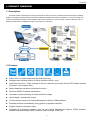
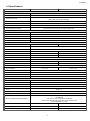
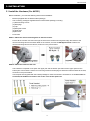
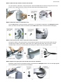
242Z
AVI321 / 311
Network Camera Series
Quick Guide
All lead-free products offered by the company comply with the requirements of the
European law on the Restriction of Hazardous Substances (RoHS) directive, which
means our manufacture processes and products are strictly “lead-free” and without the
hazardous substances cited in the directive.
The crossed-out wheeled bin mark symbolizes that within the European Union the
product must be collected separately at the product end-of-life. This applies to your
product and any peripherals marked with this symbol. Do not dispose of these products
as unsorted municipal waste. Contact your local dealer for procedures for recycling this
equipment.
Please read instructions thoroughly before operation and retain it for future reference.
AVI321, 311 quick_V0.81
OVERVIEW
1. PRODUCT OVERVIEW
1.1 Description
This PTZ network camera series is a high-performance device for use in professional and demanding surveillance
situation. It supports multiple network protocols for MPEG4 or MJPEG live video transmission, and you can easily view,
record and operate the camera via the supplied video viewer software or the web browser. Video surveillance over IP
network infrastructure is available and easy from anywhere, at anytime.
1.2 Features
Built-in 22x / 3x optical zoom lens with auto focus lens
Intelligent auto tracking function to follow intruders (AVI321 only)
Area Zoom functions – Draw a square in the live view with your mouse and the PTZ network camera
will zoom in the assigned area.
Motion detection and alarm notification functions
Real time MPEG-4 network transmission
Low-latency video streaming for sharp and clear images
Hybrid digital / analog video output
Control network camera via Central Management System (CMS) software
Excellent precision controllability using joystick or keyboard controller
Support external microphone input
Complete IP surveillance system, such as the Central Management System (CMS) software,
Network-Attached Storage (NAS), Network Video Recorder (NVR), etc.
-1-
OVERVIEW
1.3 Package Contents
‧
AVI321
◎ In the camera package:
□ 22X PTZ network camera
□ CD-ROM disc for user manual
◎ In the bracket package (Optional) :
□ Bracket
□ Wall mounting screw * 4
□ Wall plug * 4
□ CD-ROM disc for Video Viewer AP Software
□ Cap * 1
□ M6 Nylok screw * 6
□ Spirit level * 1
□ M4 screw * 1
‧
AVI311
□ 3X PTZ network camera
□ Screw * 3
□ CD-ROM disc for user manual
□ Wall Plug * 3
□ CD-ROM disc for Video Viewer AP Software
□ Decoration Cover * 3
Note: The DC12V 1A adapter, power cord and RJ45 network cable are not included with the sales package.
Please prepare by yourself.
-2-
OVERVIEW
1.4 Specifications
SPECIFICATIONS*
AVI321
AVI311
▓ Network
LAN Port
YES
LAN Speed
10/100 Based-T Ethernet
DDNS, PPPoE, DHCP, NTP, SNTP, TCP/IP,
ICMP, SMTP, FTP, HTTP, RTP, RTSP
Supported Protocols
Frame Rate
NTSC:30, PAL:25
Number of Online Users
10
Security
Web management software
Multiple user access levels with password
YES (Control up to 16 network cameras simultaneously)
▓ Video / Audio
Video Compression
MPEG4 / MJPEG
Video Remote Control
YES
Video Adjustment
Brightness, Contrast, Saturation and Hue
Audio Compression
uLaw , 128kbps
Audio Input
External Microphone Input
▓ Camera
Image Sensor
1/4" Sony Color Super HAD CCD
Pixels
768(H)*494(V)<NTSC> / 752(H)*582(V)<PAL>
Resolutions
Lens
F-number
Viewing Angle
1/3" Sony Color Super HAD CCD
480 TVL
f3.9 ~ 85.9mm
f4.2 ~ 12.7mm
F1.6 (Wide) ~ 3.7 (Tele)
F2.6 (Wide) ~ 4.3 (Tele)
4∘~ 80∘
26.7° ~ 80°
Pan Range
360∘
Tilt Range
90∘
Zoom
Max Speed
22X Optical Zoom (f3.9 ~ 85.9mm)
3X Optical Zoom (f4.2 ~ 12.7mm)
Pan 360º/s, Tilt 90º/s
Pan 27º/s, Tilt 18º/s
Shutter Speed
Min Illumination
1 / 60 (1/50) to 1 / 100,000 sec.
1 Lux / F1.6
1.5 Lux / F2.6
Video Output
1.0 Vp-p. 75Ω
BLC
On / Off
White Balance
ATW
Camera ID
0~255
▓ Others
Remote Control
YES
Motion Detection
YES
Alarm and event Notification
Image upload over FTP and Email
General I/O
Alarm in x1
Power
12VDC, 1A
Operating Temperature
0~40℃
Humidity
Minimum Web Browsing Requirements
Dimension (L x W x H)
Shipping Weight
Indoor / Outdoor Application
85%
‧Pentium 4 CPU 1.3 GHz or higher, or equivalent AMD
‧256 MB RAM
‧AGP graphics card , Direct Draw, 32MB RAM
‧Windows XP, Windows 2000 Server, ME, 98, DirectX 9.0 or later
‧Internet Exploerer 6.x or later
145(D) x 184(H) mm
134(D) x 122(H)
NA
NA
Outdoor
Indoor
* The specifications are subject to change without notice.
-3-
CONNECTOR OVERVIEW
2. CONNECTOR OVERVIEW
2.1 CONNECTOR OVERVIEW
CONNECTOR
DESCRIPTION
Power Connector
Connect the DC 12V adapter for power supply.
Video Output Connector
Connect to the video input connector of your monitor with a video cable (i.e. a RCA line with the
BNC connector, or a coaxial line) for video output.
* The video cable is not included with the sales package.
Audio Input Connector
Support the connection to an audio device, such as a microphone, for voice transmission of the
local side.
RJ11 Connector
Get a RJ11 line with the proper length to your connection.
Different RJ11 line may have different line layout, so the connection might be different. If you
cannot control the PTZ network camera after connection, please reverse the RJ11 line layout and
try again.
RJ45 Jack Connector
Get a R45 network cable with the proper length to your connection. And connect the network
camera to the network.
-4-
INSTALLATION
3. INSTALLATION
3.1 Install the Hardware (For AVI321)
Before installation, you need the following items before installation:
‧
Bracket (supplied with the bracket sales package)
‧
The accessory packages supplied with the bracket sales package, including:
(1) Wall mounting screws
(2) Wall plugs
(3) Cap
(4) M6 Nylok screws
(5) Spirit level
(6) M4 screw
‧
Power Drill
STEP 1: Attach the camera-mounting base to the PTZ camera.
Put the all the camera connectors through the hole of the camera-mounting base. Align the breach of the
camera-mounting base to the sticker label on the camera, and use two M6 Nylok screws to attach the
camera-mounting base to the camera, as shown in the picture below.
STEP 2: Attach the bracket to the wall.
The bracket is composed of two parts: the upper part and the bottom part. Remove the upper part from the
bottom part of the bracket. Use the four mounting screws and wall plugs to attach the bottom bracket to the wall,
as shown in the picture below.
Use the spirit level supplied with the bracket package to check the surface is horizontal or not. If the surface is
horizontal, the bubble will remain in the center circle of the spirit level.
-5-
INSTALLATION
STEP 3: Attach the PTZ network camera to the bracket.
Turn the camera up side down, and put the power, video and RS485 data connectors through the hole of the
bracket. Then, slightly secure the camera and the bracket with three M6 Nylok screws.
STEP 4: Check the surface is horizontal or not.
Use the spirit level to check the surface is horizontal or not, and adjust the tightness of the M6 Nylok screws.
When you make sure the surface is horizontal, use the M4 screw to fix the camera and the bracket tightly.
STEP 5: Connect the power, video, audio, RJ11, RJ45 connectors.
Arrange the cables in the proper position. Put the cables through the slot and connect the camera with the
indicated power adapter, video cable, audio cable, RJ11 cable and RJ45 cable. After connection, use the
insulation tape to cover the connected wires and arrange the cables in the proper position again.
STEP 4: Replace the upper part of the bracket and finish the installation.
Replace the upper part of the bracket and fasten the bracket with a M6 Nylok screw. Then use the cap supplied
with the package to cover it and finish the installation.
-6-
INSTALLATION
3.2 Install the Hardware (For AVI311)
Before installation, you need the following items before installation:
‧
The accessory package which includes:
(1) Wall mounting screws
(2) Wall plugs
(3) Decoration covers
‧
Power Drill or screwdriver
STEP 1: Mount the camera to the ceiling.
Attach the camera to the ceiling, and fasten the camera with the supplied 3 screws.
STEP 2: Push the decoration covers to the camera to lock.
When the camera is mounted, find the supplied 3 decoration covers in the accessory package, and push them to
the camera to lock as shown below.
STEP 3: Connect the power, video, audio, RJ11, RJ45 connectors.
Please refer to Step 5 in “3.1 Install the Hardware (For AVI321)”.
-7-
INSTALLATION
3.3 Assign an IP address and Access the Camera
Step 1. Install the Software
Place the supplied Video Viewer AP software CD into your DVD- / CD-ROM drive. The installation process will
automatically start. Follow the on-screen instructions to install the application programs. After installation, a “Video
Viewer” shortcut icon will be shown on your PC desktop.
Step 2. Connect the network camera to the Internet access via a RJ-45 network cable.
Step 3. Search the available IP address to login
a)
Double-click “
Book” (
b)
” icon on your PC desktop to enter the Video Viewer control panel. By defaults, the “Address
) panel will be displayed on the right side of the Video Viewer control panel.
Click ”
” (Search)
”
” (Refresh) to search the available IP address(es). The found address(es)
will be listed, and can be added into the address book by clicking ”
For details, please see “
” (Add into address book).
” (Search) at page 11.
c)
Select the IP address you just added into the address book, and click “
d)
Double-click the IP address in the address book to login.
” (Edit) to edit the settings.
Note: For detailed network settings under different network types (Static IP / PPPOE / DHCP), please refer to
your user manual.
‧ If you cannot search any available IP address, please follow the instructions below.
Step 4. Add the IP address and other network settings to login
a)
Double-click “
” icon on your PC desktop to enter the Video Viewer control panel. By defaults, the “Address
Book” panel will be displayed on the right side of the Video Viewer control panel.
b)
c)
The default network camera settings are as follows:
Item
Default Setting
IP Address
192.168.1.10
User Name
admin
Password
admin
Port Number
80
Click ”
” (Address Book)
”
” (Add) button to key in the IP address, user name, password, and
port number of the network camera you intend to connect.
d)
Item
Default Setting
IP Address
192.168.1.10
User Name
admin
Password
admin
Port Number
80
Double-click the IP address you just added into the address book to login.
-8-
APPENDIX 1 DEFAULT VALUE
4. VIDEO VIEWER BASIC OPERATION
4.1 The Live View Page
After setting up the network information, login user name and password, double-click “
” on the PC desktop to open
and log into the Video Viewer control panel. You will see a screen similar to the following with 6 major sections:
‧ Connect to only one network camera
‧ Connect to multiple network cameras (ex. 4 cameras)
‧ 1-cut display
‧ 4-cut display
NO.
Button
Function
Description
To switch to another camera view if two or more network cameras are connected,
1
Image Display
click the corresponding blue tab. The camera title shown in the blue tab can be
customized (For example, “321”, “311”, “Play1” and “Digi”). The default camera
title is “Camera1”.
Scale
Full Screen
Close
Close All
2
Address Book
Miscellaneous
3
4
/
Click to view the images in the full screen, 4-cut, 9-cut and 16-cut mode.
Click to view the images in the full screen mode. To exit the full screen mode,
press “Esc” key on the keyboard of the PC.
Click to close the current image display view.
If the image display view is closed, you will be logged out automatically.
Click to close all the current image display view.
If the image display view is closed, you will be logged out automatically.
Click to show the predefined IP address(es). You can add, remove or search the
IP address to login the network camera remotely.
Click to show the main operation functions: audio volume control, color setting,
Control
backup, record setting, server setting, upgrade, and find status log list.
Record
Click to start / stop the manual recording.
5
Snapshot
6
Information
7
PTZ
Click to take a snapshot of the current view. The snapshot will be saved in the path
you specified in Record Setting.
Click to show the current network connection details.
Click to show the PTZ control functions: auto tracking, auto move, auto pan, zoom
in, zoom out, focus near and focus far …etc.
-9-
APPENDIX 1 DEFAULT VALUE
4.2 Address Book
This view is displayed when the Video Viewer is activated for you to login / out the network camera from the current
address list, or search the available IP address as follows:
(Address Book)
Click to view the pre-defined network camera access details.
To login, choose one IP address from the address list, and click the address twice; to logout, click the connected
IP address twice.
You can also create new IP address information, or modify or remove the current IP address information.
NO.
Button
Function
Description
Click to directly add one IP address for login. Key in all the network camera
access information needed, and click “Apply” and “Close” to add the selected
address to the address book.
1
Add
2
Edit
3
Remove
4
Record
Select one current IP address from the address list, and click this button to edit
the settings.
Select one IP address from the address list, and click this button to delete it.
Check this checkbox to enable the record settings. For details, please refer to
your user manual. The default setting is unchecked.
-10-
APPENDIX 1 DEFAULT VALUE
(Search IP Address)
Click to search and view the available IP address(es) for the network connection. You can choose one address to
add into the address book, edit the details, or update the address list.
NO.
Button
Function
Description
Select from the available IP address list, and click this button. Key in the
network camera access information needed, and click “Apply” and “Close” to
add the selected address to the address book.
4
Add into
address book
5
Setting
Select from the available IP address list, and click this button to edit the setting.
6
Refresh
Click to update the available IP address list.
4.3 Manual Record
1)
Choose the record type and assign the record location
Click “
” (Miscellaneous Control) → “
” (Record Setting) to go to the “Record Setting” page. Check the record
type(s) (Manual), and assign the location to save the recordings by double-clicking the “Video Path” cell.
2)
Enable the record settings
Once the “Manual” checkbox is checked in the “Record On/Off” section, checked the “REC” box in the address book
panel “
3)
Click “
” to enable the record settings.
” (Record) button to start manual recording
Click “
” (Record) on the main control panel to start the manual recording immediately, and the recordings will be
saved in the specified location. When the record function is started, a flashing indication icon will be shown at the
bottom right corner of the image display view.
-11-
APPENDIX 1 DEFAULT VALUE
4.4 Playback
To play a recording, click “
” (Miscellaneous Control) → “
” (Status List), and select the “Record” tab. A list of
all the recordings will be shown by defaults, and you can also sort out the logs you want to speed up the search time.
For details, please refer to your user manual.
To immediately play a recording file, select a log from the list, and click “Play” button, or double-click the selected log.
Then, the playback control panel will be shown at the bottom of the main control panel similar to the following.
For the playback control panel details, please refer to your user manual.
-12-