1
Managed Storage Switch
real world solutions for storage networking
1·888·AT·VIXEL / www.vixel.com
Vixel HQ / 11911 North Creek Parkway South / Bothell, WA 98011 / USA
tel 425 806 5509 / fax 425 806 4050
Vixel Europe / P.O. Box 261 / Great Missenden / England / HP16 0XX
tel 011 44 1494 890666 / fax 011 44 1494 863331
Vixel Asia Pacific / 11911 North Creek Parkway S / Bothell, WA 98011 / USA
tel 626 858 2430 / fax 626 915 0759
Vixel China / Beijing, China / tel 10 6849 9547 / fax 10 6849 9544
All names and trademarks are the property of their respective owners. © 2001 Vixel Corporation.
All Rights Reserved. Contents subject to change. 00041235-001 Rev. A
guide
INSTALLATION&CONFIGURATION
InSpeed™ Model 335
Copyright © 2003 Vixel Corporation. All rights reserved worldwide. No part of this
document may be reproduced by any means nor translated to any electronic medium
without the written consent of Vixel Corporation.
Information furnished by Vixel Corporation is believed to be accurate and reliable.
However, no responsibility is assumed by Vixel Corporation for its use; or for any
infringements of patents of other rights of third parties which may result from its use.
No license is granted by implication or otherwise under any patent or patent rights of
Vixel Corporation.
Vixel and InSpeed™ are registered trademarks of Vixel Corporation. All other brand or
product names referenced herein are trademarks or registered trademarks of their
respective companies or organizations.
Vixel Corporation provides this manual “as is,” without any warranty of any kind,
either expressed or implied, including but not limited to the implied warranties of
merchantability or fitness for a particular purpose. Vixel Corporation may make
improvements and changes to the product described in this manual at any time and
without any notice. Vixel Corporation assumes no responsibility for its use, nor for any
infringements of patents or other rights of third parties that may result. Periodic changes
are made to information contained herein; although these changes will be incorporated
into new editions of this manual, Vixel Corporation disclaims any undertaking to give
notice of such changes.
Vixel Corporation, 11911 North Creek Parkway South, Bothell, WA 98011
Part Number 00041363-001 Rev. A
i
Table of Contents
1
Introduction................................................................... 1
2
Installation..................................................................... 3
3
Management ................................................................ 11
4
Technical Reference...................................................... 54
A p p e n d i x e s . . . . . . . . . . . . . . . . . . . . . . . . . . . . . . . . . . . . . . . . . . . . . . . 57
A
Specifications .............................................................. 58
B
CLI Console Commands ............................................. 60
C
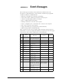
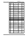
Event Messages ........................................................... 63
D
Loop ID—AL_PA Cross References ............................ 67
E
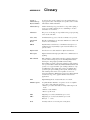
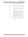
Glossary...................................................................... 68
Index .................................................................................. 70
ii
CHAPTER 1
Introduction
About This Guide 1
Overview 1
Features 1
Fibre Channel-Arbitrated Loop 2
InSpeed™ Technology 2
Important safety, electromagnetic compatibility, and regulatory information is
contained in the guide titled Safety & Regulatory Guide. The installation and use of
this product must be in accordance with the information given in that guide.
A bo ut T h i s G u i de
This guide is designed to provide the user with the necessary information to install the
Vixel Model 335 Switch and associated Small Form-Factor Pluggable Transceivers
(SFPs) for use in Fibre Channel applications in typical Storage Area Networks (SANs).
O v e rv i e w
The twelve-port switch provide 1 or 2 Gigabit per second (Gb/s) Fibre Channel support
and the flexibility of SFP-based design in a 1U full-rack size. The switch is designed as a
twelve-port central interconnect for Fibre Channel applications and supports the ANSI
FC-AL standard.
Note: Nodes include host
computers, servers, and
storage arrays.
Devices are connected to the switch through Small Form-factor Pluggables (SFPs)
transceivers and cables. Each attached node has 1 or 2 Gigabit-per-second (Gb/s) of
available bandwidth; however, all ports must be set to the same speed. Ports with no
inserted SFPs or with inoperative nodes are bypassed. The switch’s LED indicators
provide status information to service personnel to indicate whether the port is active or
bypassed.
F e a t u r es
The switch incorporates the following features:
•
InSpeed™ Te chn ology
•
Operating speeds of either 1.0625 or 2.125 Gb/s.
•
Standard 1U size for easy installation into standard rack or placement on a tabletop.
•
Twelve SFP ports for total cabling flexibility and scalability.
•
Management through the switch’s integrated web server or command line interface
(CLI).
•
10BaseT Ethernet and RS-232 Serial ports on the switch.
•
Switching and non-switching operating modes.
•
System and port status LED indicators
•
Auto-sensing, universal power supply supporting 100 to 250 VAC and 50 or 60 Hz.
1
Vixel Model 335 Installation & Configuration Guide
CHAPTER 1 Introduction
F i b r e C h a n n e l - A r b i t ra t e d L o o p
The Fibre Channel-Arbitrated Loop (FC-AL) is an ANSI standard (X3T11) designed to
provide shared bandwidth over low-cost media. Early adopters primarily use the SCSI
protocol transported over Fibre Channel for distributed server and storage cluster
applications. The switch is a central point of interconnect designed to maintain a faulttolerant physical loop topology.
I n S p e e d ™ Te c h n o l o g y
Vixel’s InSpeed™ technology enables the switch’s router to properly utilize the switch
core in sending data from one port to another. This process allows for multiple,
simultaneous conversations between ports — effectively multiplying bandwidth. Using
an advanced switching architecture that couples a non-blocking crossbar switch with
unique port logic and per-port SERDES', the InSpeed™ technology creates the industry’s
highest-density Fibre Channel switch.
This technology provides the same performance as switches that support FC-SW2, while
solving the latency problems associated with large FC-AL loops. During initialization,
InSpeed™ connects all devices together in a standard FC-AL2 loop. Upon completion of
the initialization process, InSpeed™ transitions to switching mode. When arbitration is
attempted, InSpeed™ analyzes connections and routes traffic directly to the destination
port.
The InSpeed™ switch is bufferless and operates on only the lower seven bits of the full
Fabric address field. Aside from the time it takes to complete a LIP sequence, the switch
operates at full switching bandwidth that reaches wire speeds of 200 MB/s.
2
Installation
CHAPTER 2
Unpacking the Switch 3
Installing the Switch 3
Using Small Form-Factor Pluggable (SFP) Transceivers 4
Performing a Power On Systems Test 4
Setting Up the Switch 5
Attaching Devices 5
Understanding the Switch’s LEDs 6
Cascading Switches 9
Unpacking the Switch
To unpack the switch:
1. Inspect the outer shipping container for any damage that may have occurred in
shipping and report any sign of damage to the appropriate shipping agency.
2. Remove the switch from the shipping container; save the shipping container, foam,
and anti-static bags—returning the switch in any other container or packing material
may void its warranty.
3. Inspect the switch thoroughly. (If any signs of damage are seen, notify your sales
representative and/or the shipping agency.)
I n s t al l i n g t h e S w i t c h
You can install the switch into an equipment rack or place it on a desktop.
Note: For information on
environmental
requirements, see
“Operating Conditions” on
page 59.
To mount the switch in a rack, consult the installation documentation that shipped with
the rack-mounting kit (ordered separately).
To place the switch on a desktop:
1. Turn the switch upside down so the case bottom is facing up.
2. Install a self-adhesive pad on each corner of the switch (prevents surface damage) at
the corner marks on the switch underside.
3. Turn the switch right side up so the case bottom is facing down.
Note: The plug on the
power cord is intended to
serve as the disconnect
device. To cycle power to
the switch, remove and
reconnect the switch’s
power cord.
4. Attach one end of the switch’s power cord to the switch’s power inlet socket and the
other end to a properly earthed receptacle (outlet).
5. Insert the power cord firmly into the power inlet socket.
The switch is now powered on. The switch automatically executes a Power-On Self
Test (POST) and its LEDs display the test results (for a description of the POST
sequence, see “Performing a Power On Systems Test” on page 4).
3
Vixel Model 335 Installation & Configuration Guide
CHAPTER 2 Installation
U s i n g S m a l l F o rm - F a c t o r P l u g g a b l e (S F P ) Tr a n s c e i v e rs
The switch supports any SFP module that complies with the SFP specification as
produced by MSA consortium.
The SFPs are “hot-pluggable” into the switch which allows host computers, servers and
storage modules to be added dynamically without requiring power removal from the
switch or any connected devices.
Small Form-Factor Pluggable (SFP) Installation
An SFP plugged into the switch will be automatically inserted when it is ready to begin
initialization.
To insert an SFP, slide the SFP into the port, ensuring the correct orientation, until the
latch clicks into place.
Small Form-Factor Pluggable (SFP) Removal
Removal of SFPs from a switch port causes the automatic bypass of that port. The
remaining switch ports continue to operate normally with no degradation of system
performance.
To extract an SFP, determine first what kind of extraction mechanism the SFP has.
Note: Most SFPs require
you to remove the cable
prior to removing the SFP
from the port.
If the SFP has a removal tag, pull the removal tag to extract the SFP from the port.
If the SFP has a small plastic slider on the bottom side under the optical connector,
simultaneously push in the slider and pull out the SFP.
If the SFP has a bale (small metal clasp), unlatch the bale and pull on it to extract
the SFP from the port.
Pe r fo rm i n g a P ow e r O n S y s te m s Te s t
When the switch is powered on, the switch runs through Power-On Self Test (POST)
diagnostics to verify the fundamental integrity of the switch box.
1. All switch LEDs turn on (LEDs illuminate) for approximately two seconds during
power on, then all LEDs—except for the Power LED—turn off (LEDs extinguish).
2. If the port bypass LEDs are blinking at a constant rate and the Switch Fault LED is
on, the switch has detected a hardware fault—contact an authorized service person.
4
Vixel Model 335 Installation & Configuration Guide
CHAPTER 2 Installation
S e tt i n g U p t h e S w i tc h
Before the switch can establish communication with your network, its IP Address needs
to be changed from its default value.
To set the IP Address:
1. Attach one end of an RS-232 null modem cable to the serial port on the workstation;
attach the other end to the RS-232 port on the switch.
2. For Unix workstations, type the following command at a Unix prompt (where
SerialPortDevicePath is the filepath to the serial port used for connection):
cu -s 19200 -b 8 -1 SerialPortDevicePath
For Windows® platforms, open a terminal session through a terminal emulation
program (such as HyperTerminal) with the appropriate serial port (for example,
COM1) and the following serial port parameters:
• Bits per second: 19200
• Data bits: 8
• Parity: None
• Stop bits: 1
• Flow control: Xon/Xoff
You are now connected to the CLI.
3. To log onto the CLI, type li at the prompt, then type the password (the default password is password).
4. To change the switch’s IP parameters, type co and then type 1 to change the switch’s
IP address.
5. If you want to change the switch’s netmask and default gateway, type 2 and 3,
respectively.
6. Type 5 to save changes and reset the management agent. (The management agent
must be reset for the change to take affect.)
7. To log off the CLI, type lo at the prompt.
For more information on configuring the switch through the CLI, see “Using the
Command Line Interface (CLI)” on page 36.
A t ta c hi n g D e v i c e s
To attach devices to the switch:
1. Insert an active (that is, Ethernet hub- or Ethernet switch-attached) Ethernet RJ-45
twisted pair cable into the switch’s 10BaseT management port and ensure that the
Enet Act (Green) LED is on (LED illuminates).
Note: You can attach cables to SFPs before or after SFP insertion (the switch
bypasses ports that do not have attached cables).
2. Remove dust covers or plugs from the SFPs, if provided.
3. For each device:
a. Attach a cable to the device.
CAUTION: Forcing an SFP
into a port may damage the
SFP and/or port.
b. Attach the other end of the cable to a SFP and insert the SFP into a switch port,
using minimal pressure and fitting the SFP housing’s integral guide key into the
port until the SFP’s tabs click into place.
5
CHAPTER 2 Installation
Vixel Model 335 Installation & Configuration Guide
Note: FC-AL compatible
nodes must perform
initialization procedures
upon power-up in order to
function properly. It is the
responsibility of the Fibre
Channel driver software on
FC-AL nodes to perform
the initialization or reinitialization (depending on
its prior state of operation).
4. Make sure the switch and any other connected switches or hubs are powered on.
5. Power on the storage devices (such as JBODs and RAIDs), then power on the hosts.
The network initializes.
6. Check all port LEDs. For more information on Port LED status, See “Port LEDs” on
page 7.
7. Check the green Switch Op (Switch Operational) LED. If the Switch Op LED is lit,
all zones with inserted devices are operational. If the Switch Op LED is blinking in a
multiple zone configuration, one or more zones are operational while others are not.
If the Switch Op LED is off, no operational zones exist or no devices are attached.
Note: Improper initialization could be the result of a defective or inoperative host
bus adapter card or device. Consult the vendor’s documentation for adapter diagnostic procedures.
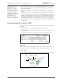
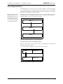
U nd e rs t a nd i ng t he S w i tch ’s L E D s
You can check the system and port status through the Light-Emitting Diodes (LEDs) on
the switch.
The switch utilizes two sets of LEDs to indicate switch and port status:
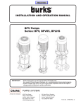
1. System LEDs – Six separate LEDs that indicate the status of the switch separate from
the Port LEDs.
2. Port LEDs – Two LEDs per switch port that indicate status of that specific port
Figure 2-1. Switch features diagram
Power On
When powering on the switch, all LEDs turn on for two seconds and then off for two
seconds except for the Power LED, which remains lit while the switch is powered.
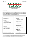
System LEDs
There are six LEDs that indicate the status of the switch, independent of the port LEDs:
Switch
Fault
Switch
Operational
Switch
Speed
Management
Present
Power
Ethernet
Active
Figure 2-2. System LEDs
6
Vixel Model 335 Installation & Configuration Guide
System LEDs
CHAPTER 2 Installation
Indication
Power
(green LED)
When lit, the switch is plugged in and the internal power
supply is functional.
Switch Fault
(yellow LED)
Indicates that the internal hardware self-test failed. When
lit, the switch will not function. -orIndicates that a fan has stopped operating or the ambient
temperature has exceeded 45°C. When lit, the switch is still
functional but requires immediate attention. The LED will
turn off when the detected condition is corrected.
Switch Op
(green LED)
Indicates whether the zones are initialized and operational.
If the Switch Op LED is lit, all zones with inserted devices
are operational. If the Switch Op LED is blinking in a
multiple zone configuration, one or more zones are
operational while others are not. If the Switch Op LED is
off, no operational zones exist or no devices are attached.
2 Gb/s
(green LED)
Indicates the current operational speed of the switch. When
lit, the switch is operating at 2 Gb/s. If unlit, the switch is
operating at 1 Gb/s.
Mgmt Present
(yellow LED)
Indicates that switch management is functioning. If
flashing, indicates that management functionality has failed
and is not communicating with the switch.
Enet Active
(green LED)
Indicates Ethernet activity on the switch and is controlled
through the Ethernet transceiver.
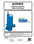
Port LEDs
Port LEDs indicate the current status of the particular port.The switch uses two port
LEDs: SFP Status and Port Bypassed/Port Activity. The Port Bypassed and Port Activity
LEDs share the same yellow/green LED.
Figure 2-3. Port LEDs
7
Vixel Model 335 Installation & Configuration Guide
CHAPTER 2 Installation
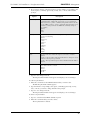
An explanation of the Port LED indicators is listed below:
SFP
Status
LED
Port
Bypassed/
Activity
LED
Off
Off
Normal status of operation for ports in which SFPs
are not installed.
The port will be in the bypass state, which precludes
the port from participating in the network.
On
Off
Normal operation. Port and device are operational.
On
On
(Yellow)
Bypass. The port is non-operational due to loss of
signal, poor signal integrity, or the attached node is
sending LIP(F8,xx).
This is the normal status condition when the SFP is
present but not attached to a FC-AL node, or if it is
only attached to a cable assembly with nothing
attached at the opposite end. Replacing such a port
(or replugging the same port twice) is considered to
be a configuration change, which should initiate the
Loop Initialization Procedure by the attached device.
Off
On
(Yellow)
Tx Fault. The port is non-operational due to an SFP
transmitter fault or improperly-seated SFP.
Off
Blinking
(Yellow)
The port is being manually controlled by a
management entity.
Blinking
Blinking
(Yellow)
A management entity is forcing a port beacon to
locate a particular port on the switch.
On
On
(Green)
A connection has been made with the port.
Note: This LED is only applicable when the port is
operating in switching mode. If the port is in
switching mode and the LED is off, the port is not
currently involved in a transaction.
Indication
8
CHAPTER 2 Installation
Vixel Model 335 Installation & Configuration Guide
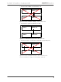
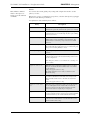
C a s ca d i ng S w i t c h e s
Cascading allows you to connect two or more switches together to increase the number
of ports and available devices. The switch allows you to link up to 12 switches. Multiple
cascades between switches provide link and communication redundancy. You may have
up to three cascades between a pair of switches.
Note: The primary switch
disables the transceivers on
all redundant connections,
so only the primary cascade
is enabled. If the primary
cascade goes down, another
cascade is then enabled.
The primary cascade is determined by the order of discovery in the primary switch (the
switch with the lower Serial Number). If the primary cascade fails in either switch, an
automatic failover occurs on one of the other cascades.
Zone 1
Zone 1
Zone 1
Figure 2-4. Cascading Switches in Overlapping Zones
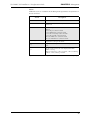
Cascading with Non-Overlapping Zones
There are certain cascade restrictions when using non-overlapping zones. The following
examples outline these restrictions.
1. You may only have multiple cascades between switches in Zone 1.
Zone 1
Zones 2-12
Zone 1
Zones 2-12
Figure 2-5. ACCEPTABLE: Multiple Cascades in Zone 1
9
CHAPTER 2 Installation
Vixel Model 335 Installation & Configuration Guide
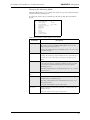
2. You may not have multiple cascades in Zones 2-12.
Zone 1
Zones 2-12
Zone 1
Zones 2-12
Figure 2-6. NOT ACCEPTABLE: Multiple cascades in Zones 2-12
3. You may have a single cascade in Zones 2-12 only.
Zone 1
Zones 2-12
Zone 1
Zones 2-12
Figure 2-7. ACCEPTABLE: Single Cascade in Zones 2-12 Only
4. You may not create a cascade in Zone 1 and another cascade in Zones 2-12.
Zone 1
Zones 2-12
Zone 1
Zones 2-12
Figure 2-8. NOT ACCEPTABLE: Cascades in Zone 1 and Zones 2-12
For more information on zoning, see “Zone Settings” on page 31.
10
CHAPTER 3
Management
Overview 11
Using the Web Manager 11
Using the Command Line Interface (CLI) 36
O v e rv i e w
The switch utilizes both a Web Manager interface and a Command Line Interface (CLI)
to manage the switch. You can change the switch’s device identification, upgrade
firmware, configure switch settings and policies, define severity levels for event
messages, and configure zoning.
U s i n g t he We b M a n a g e r
The Web Manager enables you to manage and monitor a switch from any networkconnected computer. (Supported browsers are Netscape Navigator 4.7 or higher and
Microsoft Internet Explorer 5.0 or higher. The browser needs to be Javascript-enabled.)
With the Web Manager, you have the added benefits of easy navigation, simultaneous
configuration of multiple ports, and named—rather than enumerated values within
complex tables.
Connecting to the Web Manager
For a workstation to connect to the Web Manager, it must have access to the network
on which the switch is connected.
If you need to verify the switch’s IP address, log into the switch’s command line interface
through a serial link (see “Connecting to the CLI” on page 36).
To connect to the Web Manager:
1. Make sure the switch is connected to your network.
2. On a network-connected computer, open a web browser (such as Netscape
Navigator or Microsoft Internet Explorer); in the URL text box, enter the switch’s
address (DNS name or IP Address).
11
Vixel Model 335 Installation & Configuration Guide
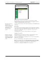
CHAPTER 3 Management
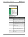
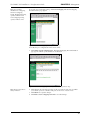
Figure 3-1. Web Manager Home Page
The Web Manager for the selected switch appears, and monitoring is available.
Configuration links and elements are visible only when you are logged in, as noted in
“Using the Command Line Interface (CLI)” on page 36.
Note: The web browser’s
appearance and
information depends on the
switch’s active firmware
version and may change
without notice in
subsequent firmware
versions.
To display updated information while using the Web Manager, click the Refresh button
on the page.
Navigation
To ensure that refreshed information is displayed, use the navigation links and buttons
(such as “Back”) that are on the Web Manager web pages. (The browser’s “Back” and
“Next” buttons usually display cached copies, which do not reflect the current
information on the switch.)
The highlighted button at the top of the page indicates your current location.
Logging On and Off
Note: For security, passwords (for accessing the
Web Manager & CLI) can
only be changed through a
serial connection to the
switch.
The Web Manager does not require log-on unless you want to modify the switch’s
parameters or configuration (such as zone or policy configurations).
To log on to the Web Manager, click Log In, type the correct password (the default is
password), and click Log On.
To log out of the Web Manager, click Log Out or close the browser window.
Note: One password is used to access both the Web Manager and the Command Line
Interface. You can change the password through the Command Line Interface (CLI)
only. Make sure you change the password after you log on the first time (for
instructions, see “Changing the CLI/Web Password” on page 43).
12
CHAPTER 3 Management
Vixel Model 335 Installation & Configuration Guide
Configuring the Switch
A quick list of frequent configuration tasks and their locations is shown here. More
detailed information on each configuration task follows the table. Once you reach the
location, you may need to click Change Settings and/or other links or buttons before
configuration parameters are available for changing.
Configuration Task
Change the switch speed
Location in Web Manager
System > Change Settings
(See “Switch Speed” on page 16.)
Change device identification, contact, and
location
System > Change Settings
(See “Switch Identification” on page 16.)
Upgrade firmware
(See “Firmware Settings” on page 18.)
Change the network settings (IP Address,
Gateway, and Netmask)
System > Firmware
(click Load New Firmware Image)
System > Change Settings
(See “Network Settings” on page 15.)
Change the time settings
System > Time > Change Time Settings
(See “Time Settings” on page 17.)
Configure zoning
Zoning
(See “Zone Settings” on page 31.)
View & download event log
System > Event Log
(See “Event Log Messages” on page 19.)
Reset switch
Home (click Reset Switch)
(See “Resetting the Switch” on page 13.)
View & update policies
Policy
(See “Policy Settings” on page 29.)
Note: To configure switch
settings, you must be
logged into the Web
Manager.
General switch status is shown on the Home page (click Home). You can click the
options at the top of the page to view additional information and configure the switch.
These options are discussed in more detail on the following pages.
Resetting the Switch
Changes to certain switch settings require you to reset the switch for those changes to
occur. You must be logged into the Web Manager to reset the switch.
To reset the switch, click Reset Switch on the Home page.
13
CHAPTER 3 Management
Vixel Model 335 Installation & Configuration Guide
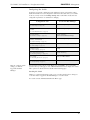
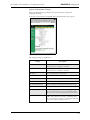
System Information Settings
The System Informations page displays the switch’s parameters and general
configuration settings.
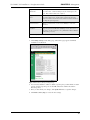
To view the system settings, click System. The System Information page appears.
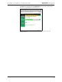
Figure 3-2. System Information Page
The displayed settings are listed below:
Setting
Description
MAC Address
A unique device address assigned to each switch at the
factory. Cannot be configured or modified.
Serial Num(ber)
A unique identification number assigned to each switch at the
factory. Cannot be configured or modified.
IP Address
The current IP Address for the switch.
IP Gateway
The current Gateway address for the switch.
IP Netmask
The current IP Netmask address for the switch.
Speed
The current speed setting for the switch.
Speed Control (Last boot)
The speed setting selected during the last switch power-up.
Speed Control (Next boot)
The speed setting selected for the next switch power-up.
Switching Mode
When "on", allows data to be sent directly to a specified port.
If "off", the data is sent to every port. Disabling Switching
Mode may be necessary when passing data to legacy devices.
Blocking ARB
When two ports start a communication session, the Blocking
ARB is sent to all other ports trying to communicate with
those ports until the connection is terminated. Blocking ARB
is only active when the switching mode is on.
14
CHAPTER 3 Management
Vixel Model 335 Installation & Configuration Guide
Setting
Description
Agent Up Time
The duration of time the switch has been operational.
Name
The name of the switch.
Location
The location where the switch resides.
Contact Name
The person’s name to contact for switch issues.
HW Version
The hardware version of the switch. Cannot be configured or
modified.
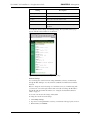
To modify the current settings, click Change Settings. The System Information page
appears with the fields available for modification.
Figure 3-3. System Information (Change Settings) Page
Network Settings
You can change the switch’s network settings (IP Address, Gateway, and Netmask)
through the Web Manager once the switch has established communications with the
network.
Note: To change the network settings of a switch that is not yet communicating with
your network, connect through a null modem serial cable and change the IP Address
through the CLI. For further information, See “Using the Command Line Interface
(CLI)” on page 36.
To view the current network settings, click System.
To change the switch’s network settings:
1. Click Change Settings.
2. Type the new setting (IP Address, Gateway, or Netmask) in the appropriate text box.
3. When finished, click Submit.
15
CHAPTER 3 Management
Vixel Model 335 Installation & Configuration Guide
4. You must reset the switch for the new network settings to become active. To reset the
switch in the Web Manager, click Home and then click Reset Switch. You may also
reset the switch through the CLI. See “Resetting the Switch” on page 51.
Switch Speed
The switch is set to 2.125 Gb/s as the factory default switch speed.
To view the current switch speed, click System.
To change the switch speed:
1. Click Change Settings.
2. From the Speed Control (Next boot) drop-down box, select the desired speed.
Setting
Description
One Gig
Set switch speed to 1.0625 Gb/s.
Two Gig
Set switch speed to 2.125 Gb/s.
3. Click Submit. The next time you reset the switch the new switch speed will be
applied.
Switching Mode
When enabled, switching mode allows data to be sent directly to a specified port. If
switching mode is disabled, the switch sends data to every port. Disabling Switching
Mode may be necessary when passing data to legacy devices.
To view the current mode, click System.
To change the switching mode:
1. Click Change Settings.
2. Select either "on" or "off" from the Switching Mode drop-down box.
3. Click Submit.
Blocking ARB
Note: This setting should
not be modified unless
directed to do so by Vixel
Customer Service.
When two ports start a communication session, the Blocking ARB is sent to any other
ports trying to communicate with those specific ports until their connection is
terminated.
To view the current Blocking ARB value, click System.
Switch Identification
You may modify the switch’s name, location, or contact name.
To view the current information, click System.
To change the switch identification:
1. Click Change Settings.
2. Enter the new value in the appropriate text box.
3. When finished, click Submit.
16
Vixel Model 335 Installation & Configuration Guide
CHAPTER 3 Management
Downloading the Switch Configuration
You can download the current switch configuration to the Web Manager. The
configuration file displays in text format.
To download the switch configuration, click Download Switch Configuration File. A
text file appears displaying the current switch configuration. You can save or print the
information.
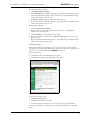
Time Settings
To view the current time settings, click System and then click Time. The Time
Information page appears.
Figure 3-4. Time Information Page
To change the time settings, click Change Time Settings. The Time Information page
appears with the fields available for modification.
Figure 3-5. Time Information (Change Settings) Page
17
CHAPTER 3 Management
Vixel Model 335 Installation & Configuration Guide
To change the Time Mode:
1. From the Time Mode drop-down box, select the desired time setting.
Setting
Description
none
The switch does not set the time.
Server
The switch receives the time from a time server via
Ethernet.
User
The user manually sets the time for the switch.
2. Click Submit.
To use a time server:
1. Select Server in the Time Mode drop-down box.
2. Enter the IP Address for the time server in the Time Server text box.
3. Enter the desired update interval in minutes in the Time Server Update Interval (min)
text box.
4. Click Sync to Server Time to immediately synchronize the server time to the time
server at the designated IP Address.
5. Click Submit.
To set the time setting to the computer connected to the switch, click the Sync to PC
Time Now Sync button and then click Submit.
Note: Clicking Back on the
browser tool bar may not
update settings due to web
browser caching pages in
memory.
To view the new time settings, click Back to Time page.
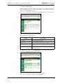
Firmware Settings
The Firmware page displays information on the current firmware version, the alternate
firmware version, and the version of the software that loads the firmware image on boot
up.
To view the current firmware settings:
1. Click System. The System Information page appears.
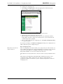
2. Click Firmware. The Firmware Information page appears.
Figure 3-6. Firmware Information Page
18
Vixel Model 335 Installation & Configuration Guide
CHAPTER 3 Management
To change the firmware settings:
1. Click Change Firmware Settings.
2. Click Switch Image for execution on next boot to swap the current firmware image
and the alternate firmware image. The page informs you of which firmware image
will be loaded on the next boot cycle.
3. Click Back to Firmware page to return to the Firmware page.
4. Review the Firmware Information display to ensure that the proper firmware image
will be loaded on the next boot cycle.
To upgrade the firmware:
1. Click Load New Firmware Image.
2. Enter the directory path to the specific file in the text box, or click Browse to
navigate to the appropriate file.
3. Click Load Image to download the firmware image.
4. Once the new image is downloaded, click Back to Firmware page to return to the
Firmware page.
5. Review the Firmware Information display to ensure that the proper firmware image
will be loaded on the next boot cycle.
Event Log Messages
The Event Log Messages page displays a list of event log messages generated by the
switch. The event log holds approximately 500 messages at a time. For a complete list of
event messages, see E VENT MESSAGES (APPENDIX C) on page 63.
To view the event log:
1. Click System. The System Information page appears.
2. Click Event Log. The Event Log Messages page appears.
Figure 3-7. Event Log Messages Page
To save the event log messages:
1. Click Download Event Log.
2. Click OK to save the file to the disk.
3. Select the appropriate directory to save the event log messages and click Save.
To clear the current list of event log messages, click the Yes button next to Clear ALL
Events.
19
CHAPTER 3 Management
Vixel Model 335 Installation & Configuration Guide
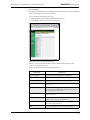
FC Switch Information
The FC Switch Information page displays the switch view by ports. Each port displays
the zone, utilization percentage, and associated ALPA(s). You can identify all ports in a
specific zone by highlighting that zone.
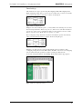
To view the switch settings, click FC Switch. The FC Switch Information page appears.
Figure 3-8. FC Switch Information Page
The displayed settings are listed below:
Setting
Description
Port number
The port number on the switch.
Zone number
The zone number to which the port is assigned.
Utilization percentage
Measures the amount of traffic that is flowing through the
port.
ALPA(s)
The Arbitrated Loop Physical Address for each device
connected to the port.
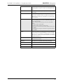
To highlight a specific zone, click the Highlight Zone drop-down box and select the
desired zone. The highlighted zone displays in color.
Figure 3-9. FC Switch Information Page with Highlighted Zones
You can also view Ordered Set and Port Usage information.
20
CHAPTER 3 Management
Vixel Model 335 Installation & Configuration Guide
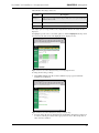
OS Information
The Ordered Sets Information page displays the Ordered Sets that are being transmitted
on the switch by their associated port number.
To view the Ordered Sets Information page:
1. Click FC Switch. The FC Switch Information page appears.
2. Click OS Info. The Ordered Set Information page.
Figure 3-10. Ordered Set Information Page
If there is a connection, then the Ordered Set transmission information for that
connection is depicted by an "X".
A list of the Ordered Sets and their indications follows:
Detection
Indication
Non-Overlap Zone
Displays the zone for which the port is configured.
Transceiver
Displays the status of the inserted transceiver in the port.
Sync
A stable signal has been detected and IDLEs transmitted.
Match
The ordered set or pattern selected under the Match area has
been detected.
EOF
An End-of-Frame (EOF) delimiter has been detected; frames are
present on the loop. (An EOF immediately follows the CRC of a
frame and signals the frame’s end.)
SOF
A Start-of-Frame (SOF) delimiter has been detected; frames are
present on the loop.
IDLE
Sequences of IDLEs are being transmitted to maintain link
activity; no other data is being transmitted.
ARBff
ARB(FF)s are being transmitted to maintain link activity; no
other data is being transmitted.
ARB
A port is arbitrating for loop access to perform a task.
21
Vixel Model 335 Installation & Configuration Guide
CHAPTER 3 Management
RRDY
The receiving node on this port has sent an R_RDY signal,
indicating that it is ready for a frame to be transmitted over the
link.
CLS
The port is attempting to begin the process of closing the current
loop circuit.
OPN
The port is attempting to open communications with another
port on the loop. Note: As is the case with some ordered sets, an
OPN may not go all the way around the loop, instead stopping
at its destination.
LIP F8
A non-switching port has detected a loop failure on its receive
input, is notifying other ports, and is determining whether the
loop is still operational.
Some events that could cause the port to detect loop failure
follow:
• A device in the loop has failed.
• A device in the loop has been powered off.
• The physical connection between the transmitter and receiver
is broken.
• Activating the port bypass circuit does not typically result in a
loop failure.
LIP F7
A loop port is in the non-participating mode and is attempting
to win arbitration and begin initialization, possibly because the
port was reset or is powering up. Sometimes the port is sending
this sequence to another, hot-cascaded switch like a new initiator
being inserted in the loop.
LIP
A Loop Initialization Primitive (LIP) sequence has been detected
and action has been taken.
Unknown
The switch can not determine what is being transmitted.
InvTxWd
An invalid transmit word has been detected.
CRC Err
A Frame CRC error has been detected.
Pt-to-Pt
A point-to-point connection has been detected.
22
Vixel Model 335 Installation & Configuration Guide
CHAPTER 3 Management
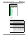
To highlight a specific zone, click the Highlight Zone drop-down box and select the
desired zone. The highlighted zone displays in color.
Figure 3-11. Ordered Set Information Page with Highlighted Zones
Port Usage Information
The Received Port Utilization page displays the ports and enables you to view the
utilization percentages to determine which ports are busy.
To view the Received Port Utilization page:
1. Click FC Switch. The FC Switch Information page appears.
2. Click Port Usage. The Received Port Utilization page appears.
Figure 3-12. Received Port Utilization Page
23
Vixel Model 335 Installation & Configuration Guide
CHAPTER 3 Management
The Utilization Percentages values are:
Value
Description
Average %
The average percentage data for the port in the zone over a period of Average
Window Size seconds.
Peak %
The Peak data communication rate usage for the port
Low %
The Low data communication rate usage for the port.
The sample period, average windows size, and peak/low window size values are also
displayed.
To highlight a specific zone to view traffic patterns, click the Highlight Zone drop-down
box and select the desired zone. The highlighted zone displays in color.
Figure 3-13. Received Port Utilization Page with Highlighted Zones
To change the Port Usage settings:
1. Click Change Settings. The Received Port Utilization page appears with fields
available for modification.
Figure 3-14. Received Port Utilization (Change Settings) Page
2. You may change the Average Sample Period and Peak/Low Sample Period values (in
seconds) by entering new values in the appropriate text boxes. The Sample Period
value cannot be modified.
24
CHAPTER 3 Management
Vixel Model 335 Installation & Configuration Guide
3. Click Submit to accept the changes.
4. Click Back to Port Usage to view the new settings.
Port Settings
The Port Information page displays the port status for each port on the switch.
To view the port settings, click Port. The Port Information page appears.
Figure 3-15. Port Information Page
The displayed settings are listed below:
Setting
Description
Port
The actual port on the switch.
Transceiver
The type of transceiver inserted in the port.
Trcvr LED
If a transceiver is inserted properly, the LED is on.
Fault LED
The port is bypassed due to a problem detected by either the
transceiver’s transmit logic or the SFP transceiver itself.
Transceiver problems include unconnected fiber, remote node
not transmitting, LIP(F8), or a faulty transceiver.
State
The current state of the selected port.
TX
The state of the transmitter on the selected port.
Inserts
The number of times a transceiver has been inserted into the
port since the last switch reset.
Freq
The port locked in on the communicating frequency for which
the switch is configured.
Zone
The zone in which the port is located.
Cascade Mode
Displays the cascade mode for the specified port.
Cascade State
Displays the cascade state for the specified port.
25
Vixel Model 335 Installation & Configuration Guide
CHAPTER 3 Management
To highlight a specific zone, click the Highlight Zone drop-down box and select the
desired zone. The highlighted zone displays in color.
Figure 3-16. Port Information Page with Highlighted Zones
To view information on a transceiver connected to a port, click serial mod def in the
transceiver column. The specific transceiver’s information displays to the right of the
current switch information.
Figure 3-17. Port Information Page with Transceiver Information
26
Vixel Model 335 Installation & Configuration Guide
CHAPTER 3 Management
To modify the port cascade settings:
1. Click Change Port Cascade Settings. The Cascade Information page appears.
Figure 3-18. Cascade Information Page
2. On this page, you can view the port settings, highlight a specific zone, or change the
port cascade mode.
3. Select the port to modify by clicking the Cascade Mode drop-down box for the
specific port.
4. Select the port cascade mode, which configures the port’s operation in the switch.
The different port cascade modes are:
Mode
Description
auto
This setting automatically configures the connection type based on
information sent by other InSpeed switches. The default setting is
Auto for InSpeed-based managed switches.
none
The port is disabled.
tree
A port that allows arbitration fairness to other cascaded InSpeedbased switches or ports connected to end devices. If the port is a tree
port then the ARB (Arbitrate) is sent down the port and, when the
ARB is received back at the ASIC, a connection is made between the
source and destination ports. All ports are viewed as 100% FC_AL
compliant.
string
A specially pre-allocated port designed to maintain fairness when
two or more InSpeed-based storage switches are serially cascaded.
When the destination port is a string and an OPN is received on the
ASIC, an ARB is transmitted throughout the total string cascade
loop to alert all devices to enforce the Loop fairness rules. Therefore,
if two devices try to ARB for the loop at the same time, the higher
Priority AL_PA will win the cascade first, the lower priority one will
follow.
Note: There must be two string ports on a zone. The port is
configured for a pair of string ports to other switches.
Each Port can operate independently of the other ports except in String mode.
27
Vixel Model 335 Installation & Configuration Guide
CHAPTER 3 Management
5. After making changes, click Submit to accept the changes.
To highlight a specific zone, click the Highlight Zone drop-down box and select the
desired zone. The highlighted zone displays in color.
Figure 3-19. Cascade Information Page with Highlighted Zones
28
CHAPTER 3 Management
Vixel Model 335 Installation & Configuration Guide
Policy Settings
Policies define switch operation and determine how the switch handles error recovery.
The Policies page displays the switch policies that are enabled or disabled.
To view the policy settings, click Policy. The Policies page appears.
Figure 3-20. Policies Page
The displayed settings are listed below:
Switch Policy
Description
Smart Insertion
When this policy is enabled, the switch LIPs on the insert of a new
port and waits for LIP(f7)s to return prior to insertion. Also ensures
that data meets the requirements of Fibre Channel Arbitrated Loop
(FC-AL) and allows sub-policies to be enabled.
Auto Cascade*
When a port is connected to another Vixel Model 335 switch, the
switch will automatically configure the port to the connected device
type.
Bad Zone recovery*
The switch reinitializes the zone and will bypass zone ports that are
down. The switch will bypass all ports when:
•
Zone 1 has a least one transceiver with a signal and the port is in
auto mode.
•
No ports in the zone are in forced insert mode (Port Control).
•
The zone state is down.
No Data Recovery*
The switch will bypass a port if no K characters (Ordered Sets) are
detected for 100 usecs. The switch will try to reinsert the port upon
detection of valid K characters.
LIP(F8) Recovery*
The switch will bypass a port if a LIP(F8) is received. The switch will
try to reinsert the port when no more LIP (F8)s are received.
LIP on Port Bypass*
When a port is bypassed, it issues LIP(F7)s to other zone members.
Bypass on Bad OS
Threshold*
When a port exceeds the threshold of Ordered Set errors within ten
seconds, the switch bypasses the port. Note: The threshold can be
adjusted. (224 – 1, the maximum expected error rate is one error
within 15 minutes.)
29
Vixel Model 335 Installation & Configuration Guide
CHAPTER 3 Management
Bypass on CRC Error
Threshold*
When a port exceeds the threshold of frame CRC errors within ten
seconds in Zone 1 and in switching mode, the switch bypasses the
port. Note: The threshold can be adjusted.
Bypass on Clock Delta
Error
When this policy is enabled, the switch compares the detected line
clock through the frame and the number of fill words inserted or
deleted versus the switch’s internal clock. If the derived clock delta is
too high, the port is bypassed.
LIP on Insertion*
When a port inserts into a zone, it issues LIP(F7)s to other zone
members.
Port Test Before
Insertion*
Before allowing a port to insert into a zone, the port is monitored for
proper Loop Port State Machine (LPSM) protocols. (At least one of
the devices on the port must be a Loop Initialization Master (LIM) to
follow these protocols.)
* To set this policy, ensure that Smart Insertion is enabled.
To update the switch’s policies:
1. Click Change Settings on the Policy page. The Policies page appears with fields
available for modification.
Figure 3-21. Policies (Change Settings) Page
2. You can select whether to enable or disable a specific policy, set thresholds on certain
policies, and select specific ports for the LIP on Insertion and Port Test Before
Insertion policies.
3. Once you have made your changes, click Update Policies to accept the changes.
4. Click Back to Policy Page to review the new settings.
30
Vixel Model 335 Installation & Configuration Guide
CHAPTER 3 Management
Zone Settings
The switch uses two types of port zoning: Overlapping and Non-Overlapping Zones.
With overlapping zoning, devices on one port are not allowed to see devices on another
port, yet those same devices can both see a device on a third port.
Figure 3-22. Overlapping Zones
In Figure 3-22, Zone 1 includes ports 1, 3, and 4, while zone 2 includes ports 2, 4 and 5.
Port 4 overlaps both zones. Devices on ports 1, 3, and 4 can see each other and devices
on ports 2, 4, and 5 can see each other, but devices 1 and 3 cannot see devices 2 and 5.
Devices on port 4 can see all the devices on ports 1, 2, 3, and 5.
Non-overlapping zoning enables the switch to be divided into separate environments,
where each environment sustains a complete 127-device AL_PA space.
Figure 3-23. Non-overlapping Zones
In Figure 3-23, Zone 1 devices operate independently of devices in Zone 2. Nonoverlapping zoning allows for true LIP isolation. If a LIP occurs in one non-overlapping
zone, it will not affect the operation or traffic occurring in a different zone.
To view the zoning information, click Zoning. The Zone Information page appears.
Figure 3-24. Zone Information Page
31
CHAPTER 3 Management
Vixel Model 335 Installation & Configuration Guide
The Zone Information page displays the current zoning configuration, the ports in each
zone, the zone state, the init count, and the time duration ("up time") for the zone. The
displayed settings are listed below:
Setting
Description
Zone number
The zone number on the switch (1-12).
Port number(s)
The port numbers that are assigned to the specified zone.
Zone state
The current state of the zone; either "up" or "down".
Init Count
The number of times a zone has transitioned from an "down" state to
an "up" state.
Up Time
The amount of time that the zone has been operational.
Overlapping Zones
Overlapping zoning can only be implemented in Zone 1 and the switch must be
operating in switching mode. To participate in overlapping zoning, each port must have
their cascade mode configured to "auto".
If the switch is operating using non-overlapping zoning, you can still configure
overlapping zoning within the default zone. If a LIP occurs on any port in the default
zone, it will affect every port in the default zone, regardless of any overlapping zone
configurations. Overlapping zones do not support LIP isolation.
To view the overlapping zoning, click Overlapping. The Overlapping Zone 1
Information page appears.
Figure 3-25. Overlapping Zone 1 Information Page
32
Vixel Model 335 Installation & Configuration Guide
CHAPTER 3 Management
To configure the overlapping ports:
1. Click Change Overlapping Zones. The Overlapping Zone 1 Information page
appears with the ports available for modification.
Figure 3-26. Overlapping Zone 1 Information (Configuration) Page
2. Click the appropriate check box for the two ports.
If the check box is selected (checked), the two ports can communicate with one
another. If the check box is empty (not checked), the two ports are blocked from
communicating with one another.
3. Once you have configured the overlapping ports, click Update Overlapping Zoning
to accept the changes.
To view the your changes, click Back to Overlapping. Blocked ports are displayed in red,
while non-blocked ports are displayed in gray.
Non-Overlapping Zones
Note: Ports 11 and 12 can
only be in Zone 1.
The non-overlapping zones feature enables you to assign each port on the switch to one
of 12 available zones. Each zone is unique which allows for 6 separate zones to function
on the same switch. With non-overlapping zoning enabled, each zone is totally
independent and LIPs on one zone do not affect the other zones.
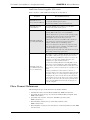
The default zone for the switch is Zone 1. Ports 11 and 12 are always included in Zone
1.
The switch provides LIP isolation through the LIP confinement properties of nonoverlapping zoning. A LIP occurring in one zone will never affect the traffic or
operations in another zone. Each zone operates completely independent of other nonoverlapping zones.
33
Vixel Model 335 Installation & Configuration Guide
Note: You can have
simultaneous overlapping
and non-overlapping
zoning. Overlapping zoning
operates in Zone 1 and
non-overlapping zoning
operates in Zones 2-12.
CHAPTER 3 Management
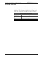
To view the non-overlapping zoning, click Non Overlapping. The Non Overlapping
Zone Information page appears.
Figure 3-27. Non-Overlapping Zone Information Page
To modify the port configurations in the various zones:
1. Click Change Non Overlapping Zones. The Non Overlapping Zones Information
page appears with the ports available for modification.
Figure 3-28. Non-Overlapping Zones Information (Configuration) Page
Note: Ports 11 and 12 are
always in Zone 1.
2. Click the Zone drop-down box for the specific port and select the zone for which
you want the port to be a member. The port can be in one of twelve zones.
3. Click Submit to accept the changes.
4. Click Back to Non-overlapping Zone Info to view the changes.
34
Vixel Model 335 Installation & Configuration Guide
CHAPTER 3 Management
To highlight a specific zone, click the Highlight Zone drop-down box and select the
desired zone. The highlighted zone displays in color.
Figure 3-29. Non-Overlapping Zones Information (Configuration) Page with
Highlighted Zones
35
Vixel Model 335 Installation & Configuration Guide
CHAPTER 3 Management
U s i n g t h e C om m a n d L i n e I n te r fa c e (C L I )
The Command Line Interface (CLI) allows you to complete several switch management
tasks over Ethernet through a telnet session or through a direct serial link. While both
the CLI and Web Manager interfaces allow you to view switch information and
configure switch settings, the CLI also allows you to enable or disable DHCP requests,
change the CLI/Web Manager password, manage traps, and complete several other
switch management functions.
Connecting to the CLI
Note: You may have up to
10 concurrent telnet
sessions accessing the
switch.
You can connect to the CLI over the telnet interface or the serial link interface.
To connect over Ethernet through telnet interface:
1. Make sure the Vixel Managed Switch is connected to an Ethernet network via the
switch’s Ethernet connection and that the monitoring workstation can access this
Ethernet network.
2. Make sure that you know the switch’s IP address before connecting to the CLI. (the
default IP Address is 0.0.0.0)
3. At a command line prompt, type telnet IP (where IP is the switch’s IP address).
You are now connected to the CLI and ready to log on.
To connect through a serial link:
1. Attach one end of an RS-232 null modem cable to the serial port on the workstation;
attach the other end to the RS-232 port on the switch.
2. For Unix workstations, type the following command at a Unix prompt (where
SerialPortDevicePath is the filepath to the serial port used for connection):
cu -s 19200 -b 8 -1 SerialPortDevicePath
3. For Windows® platforms, open a terminal session through a terminal emulation
program (such as HyperTerminal) with the appropriate serial port (for example,
COM1) and the following serial port parameters:
• Bits per second: 19200
• Data bits: 8
• Parity: None
• Stop bits: 1
• Flow control: Xon/Xoff
You are now connected to the CLI and ready to log on.
Logging On and Off
To log onto the CLI (once connected as shown above), type li at the prompt, then type
the password (the default password is password).
To log off the CLI, type lo at the prompt.
Make sure you change the password after you log on the first time.
36
Vixel Model 335 Installation & Configuration Guide
CHAPTER 3 Management
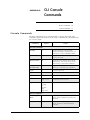
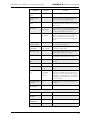
Configuring the Switch
The CLI enables you to configure the switch settings, policies, and zoning.
A list of frequent switch configuration tasks and their commands is shown here. Refer to
the provided page number for more detailed information on each configuration task.
Configuration Task
Change the IP parameters
CLI Command
co
(See “Changing the Switch’s IP Parameters” on page 38.)
Change switch identification, contact, location, etc.
si
(See “Configuring Switch Information” on page 38.)
Upgrade firmware
fw
(See “Managing the Firmware” on page 39.)
Add or delete a trap destination (through the
Configuration menu)
ct
(See “Configuring the Trap Destination Table” on page 41.)
Changing the password
pw
View switch management, policies, error thresholds, and
other switch settings.
mc
(See “Viewing Management, Policy, and Threshold Settings” on
page 43.)
Change the switching mode
sw
(See “Changing the Switching Mode” on page 47.)
Configure zoning
(See “Viewing and Understanding Zoning Information” on
page 52.)
oz
(for overlapping zoning)
noz
(for non-overlapping zoning)
Reset switch
rs
(See “Resetting the Switch” on page 13.)
Reset switch to factory default settings
rc
(See “Resetting the Switch to Factory Default Settings” on
page 51.)
View & modify port settings
po
(See “Displaying Ports” on page 49.)
Change the switch speed
lsp
(See “Changing the Switch’s Operating Speed” on page 52.)
View the event log
ev
(See “Viewing the Event Log” on page 51.)
To view the complete list of available switch commands while using the CLI, type ? or h
at the prompt. For a complete listing of all CLI commands, see CLI C ONSOLE
C OMMANDS (APPENDIX B) on page 60.
37
CHAPTER 3 Management
Vixel Model 335 Installation & Configuration Guide
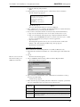
Changing the Switch’s IP Parameters
To view the current switch configuration, type co at the prompt. The Configuration
Menu appears:
CONFIGURATION MENU
1.
2.
3.
4.
IP Address
Netmask
Default Gateway
DHCP
ACTIVE VALUE
172.16.52.2
255.255.240.0
172.16.48.1
Disabled
SAVED VALUE
172.16.52.2
255.255.240.0
172.16.48.1
NEW VALUE
5. Save changes and reset switch
6. Save changes and exit menu
7. Discard changes and exit menu
Before the switch can establish communication with your network, its IP address needs
to be changed from its default value.
To change the switch’s IP parameters:
1. Type the option number (1-4) of the desired setting.
2. Enter a new value for that setting.
3. Type 5 to save changes and reset the switch. (The switch must be reset for the change
to take affect.)
Enabling or Disabling DHCP Requests
When DHCP is enabled, the switch sends a DHCP request for its correct IP parameters
(address, subnet mask, and default gateway) during power on. If a DHCP server
responds, the switch automatically changes its IP settings.
Note: The default setting
for the DHCP option is
"disabled".
If you want to enable DHCP, ensure that there is a DHCP server connected to the same
subnet as the switch. (For instructions on setting the switch’s IP parameters through a
DHCP server, see the server documentation.)
If DHCP is enabled and a DHCP server is not found, the DHCP request will fail and the
switch’s IP parameters will be incorrect. You will then have to connect through the serial
port using the CLI, disable the DHCP mode, and manually configure the switch
parameters.
To enable automatic DHCP requests from the switch:
1. Type co, then type 4.
The DHCP status is toggled to either enable or disable and the current setting is
displayed.
2. Type 5 to save changes and reset the switch. (The switch must be reset for the change
to take affect.)
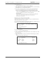
Configuring Switch Information
To change the switch name, location, or contact name, type si at the prompt. The
System Information Menu appears:
SYSTEM INFORMATION MENU
1. Switch Name:
2. Location:
3. Contact Name:
4. Exit menu
demo
lab
John Smith
To change the information:
1. Type the option number (1-3) of the desired setting.
2. Enter a new value for that setting.
3. Type 4 to exit the menu.
38
Vixel Model 335 Installation & Configuration Guide
CHAPTER 3 Management
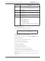
Managing the Firmware
To view the current firmware settings and a complete list of commands, type fw at the
prompt. The Internal Firmware Versions list and Firmware Menu appear:
Internal Firmware Versions:
-----------------------------------------------------CURRENT:
V2.01 (build 79)
Mar 23 2002
00:48:59
ALTERNATE: V2.00 (build 69)
Feb 27 2002
17:30:42
BOOT:
V1.01 (build 55)
Nov 9 2001
11:11:23
FIRMWARE MENU
1. Show versions
2. Select alternate version
3. Load new firmware via Ethernet
4. Load new firmware via serial
5. Reboot
6. Exit menu
The Internal Firmware Versions list displays the current and alternate firmware loaded
on the switch. The Boot firmware is installed during the manufacturing process and
manages the loading of the current firmware on the switch during power-up. The Boot
firmware cannot be configured or modified.
To select the alternate firmware version, type 2 at the prompt. A message appears
informing you that the Alternate firmware version has been selected and will load on the
next switch boot.
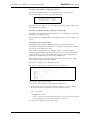
Downloading New Firmware
You can use either of the following available download methods for Windows; for Unix
workstations, use the Ethernet (TFTP) method.
To download firmware from a binary file, type fw and choose the desired downloading
method.
Ethernet (TFTP) Method (Menu Option 3)
Use the Ethernet (TFTP) method for Unix workstations (this method can also be used on
Windows NT workstations).
Note: The “Destination:”
message varies according to
the active firmware image
and the platform you are
using. See Step 2.
1. Type: 3 at the prompt.
The following message appears.
Ready for TFTP file transfer
IP address: IPaddressForYourCard
Destination: ramdisk
2. For Windows:
• Use a command line to move to the directory containing the new firmware and
type the following (where IPaddress is the switch’s IP address and filename is
the name of the binary firmware file) and press Enter.
tftp -i IPaddress PUT filename ramdisk
Within a few seconds, the “Transfer successful” message appears. (If the message
does not appear, verify that the file is good and repeat the transfer.)
3. For Unix workstations:
a. At a Unix prompt, type the following (where IPaddress is the switch’s IP
address) and press Enter.
tftp IPaddress
b. Type the following and press Enter.
binary
c. Type the following (where filename is the name of the binary firmware file) and
press Enter.
put filename /ram
A message appears confirming that the file was sent.
39
Vixel Model 335 Installation & Configuration Guide
CHAPTER 3 Management
d. Type the following and press Enter.
quit
4. In the terminal session window, type 1 to verify and store the new firmware.
The following message appears.
Clearing backup host filename..
Clearing backup host IP address..
Verifying file integrity..
Erasing flash memory..
Programming flash memory..
Verifying..
*PROGRAM LOAD SUCCESSFUL*
Type fw, then type 1.
The active and alternate firmware versions are displayed.
5. If the “alternate version” is anything other than the firmware you just downloaded,
verify that the file is good and repeat the download.
6. If you want to activate the alternate version (the newly downloaded firmware):
a. Type 2 to select the alternate version for execution on the next boot cycle.
b. Type 1 to verify that the following message is displayed under the firmware
versions: “Note: ALTERNATE selected for execution on next boot cycle.” (If this
message is not displayed, repeat steps a and b to toggle back.)
c. Type 5 to reboot.
The management agent disconnects, reboots, and activates the downloaded
firmware. The “Disconnecting and Rebooting” message appears.
The firmware is downloaded.
Serial Method (Menu Option 4)
The Serial method for downloading firmware is available for Windows only.
1. Ensure that the switch and workstation are connected through a serial null modem
cable.
Note: To cancel out of the
file transfer facility, press
CTRL+X several times.
2. Type 4.
The file transfer facility appears.
3. Choose Send File from the Transfer pull-down menu in HyperTerminal.
The Send File dialog box appears.
4. Type (or browse for) the filename, select “1K Xmodem” from the Protocol dropdown list, and click Send.
A status message appears.
5. If the status message says anything other than “File transfer completed,” perform the
action recommended for the appropriate message shown below.
Message
Action
CRC Error
Try another file. The file you are attempting to download may be corrupted.
Time out error
Cycle power to the switch and retry the download procedure.
Access denied
Close and reestablish the connection. Cycle power to the switch and retry the
download procedure.
40
CHAPTER 3 Management
Vixel Model 335 Installation & Configuration Guide
6. Type fw, then type 1.
The active and alternate firmware versions are displayed.
7. If the “alternate version” is anything other than the firmware you just downloaded,
verify that the file is good and repeat the download.
8. If you want to activate the alternate version (the newly downloaded firmware):
a. Type 2 to select the alternate version for execution on the next boot cycle.
b. Type 1 to verify that the following message is displayed under the firmware
versions: “Note: ALTERNATE selected for execution on next boot cycle.” (If this
message is not displayed, repeat steps a and b to toggle back.)
c. Type 5 to reboot.
The management agent disconnects, reboots, and activates the downloaded
firmware. The “Disconnecting and Rebooting” message appears.
The firmware is downloaded.
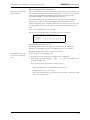
Configuring the Trap Destination Table
Simple Network Management Protocol (SNMP) uses traps to transmit information to
other IP Addressable devices on the network.
To view the current Trap Destination settings and a complete list of commands, type: ct
at the prompt. The Trap Destination Table Menu appears:
TRAP DESTINATION TABLE MENU
IP ADDRESS
Event traps: <none>
FcMgmt traps: <none>
PORT
SEVERITY
COMMUNITY
STATE
1. Create new TRAP destination
2. Delete TRAP destination
3. Exit menu
To create a trap destination:
1. Type 1 to create the new TRAP destination.
2. At the resulting IP address prompt, type the address of the workstation you would
like the trap sent to.
3. At the resulting UDP Port prompt, type the number of the listening port (usually
“162”).
The Edit Trap Destination Menu appears.
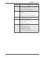
EDIT TRAP DESTINATION MENU
ACTIVE VALUE
IP Address 172.16.52.2
Port
162
1. Community 'public'
2. Severity
Warning
3. State
Inactive
4. Mode
Event
NEW VALUE
172.16.52.2
162
'public'
Warning
Inactive
Event
5. Save changes and exit menu
6. Discard changes and exit menu
41
CHAPTER 3 Management
Vixel Model 335 Installation & Configuration Guide
4. If you want to edit any of the listed options, type the number corresponding to the
desired option (community [password], severity, state, or mode) and follow the
prompts.
Option
Description
Community
Sets the community string to public or private. An SNMP server has a
"community string" which is like a password to get or set information.
Most devices have a "public" community string, which enables read-only
access to MIBs, as well as a "private" community string that enables you to
read and set certain parameters via SNMP. The community strings are
case-sensitive.
Options:
public
private
Severity
Select the severity level at which the traps become operational. The default
severity level is Warning.
Options:
0-Emergency
1-Alert
2-Critical
3-Error
4-Warning
5-Notice
6-Info
7-Debug
8-Mark
State
The state menu choice enables the trap to become active or inactive.
Options:
1-Destroy – the trap will be deleted from the table once changes are saved.
2-Inactive – the trap is not operational.
3-Active – the trap sends messages to the host identified in the IP Address
selection.
Mode
Determines whether the traps are accessed through the Event interface, the
Fibre Alliance interface, or both.
Options:
1-Event
3-FcMgmt
4-Both
5. Type 5 to save changes and exit.
The Trap Destination Table menu appears and displays your saved changes.
To edit a trap destination:
1. Enter the row number for the TRAP destination that you want to edit.
The Edit Trap Destination Menu appears.
2. Type the number corresponding to the option (community [password], severity,
state, or mode) you want to change and follow the prompts.
3. Type 5 to save changes and exit.
The Trap Destination Table menu appears and displays your saved changes.
To delete a trap destination:
1. Type 3 to select the Delete TRAP destination option.
2. Enter the row number that you want to delete.
The trap destination is deleted.
42
Vixel Model 335 Installation & Configuration Guide
CHAPTER 3 Management
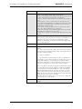
Changing the CLI/Web Password
Note: If you do not
remember your password,
call your customer service
representative.
One password is used to access both the Web Manager and the Command Line
Interface. You can change the password through the Command Line Interface (CLI)
only. The password must be between 6 and 25 characters in length.
To change the password:
1. Type pw at the prompt.
2. Enter the current password (the default password is password).
3. Enter the new password.
4. Confirm the new password by re-entering it.
A message appears confirming that the password was saved and activated.
>pw
enter current password: ********
enter new password
: ******
re-enter new password : ******
The new password is saved and activated.
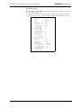
Viewing Management, Policy, and Threshold Settings
The Management Agent menu displays the current settings for the switch parameters,
switch policies, and thresholding. To view the current Management Agent settings and a
complete list of commands, type mc at the prompt. The Management Agent Menu
appears.
MANAGEMENT AGENT 00-10-9b-01-0c-dd
Product
: Vixel 335 Managed Storage Switch
Firmware
: 2.01 (build 79)
Hardware
: 3
IP address
: 172.16.71.14
Netmask
: 255.255.240.0
Default gateway
: 172.16.64.1
DHCP
: disabled
Management URL
: http://172.16.71.14
POLICIES:
(1)
Smart insertion
: enabled
(2)
Bad zone recovery
: disabled
(3)
No data recovery
: disabled
(4)
LIP F8 recovery
: enabled
(5)
LIP on port bypass
: enabled
(6)
Auto cascade
: enabled
(7)
Bypass at max OS err
: disabled
(8)
Bypass at max CRC err
: disabled
(9)
Bypass on clock delta err : disabled
(10)
Bypass on switch stall
: disabled
(11)
Clear conn on sw stall
: disabled
HW I/F:
ASIC build number
: 0x0001
(12)
OS error threshold
: 3 (0x3)
(13)
CRC error threshold
: 3 (0x3)
(14)
Switch stall threshold
: 65535 (0xFFFF)
(15)
Clk error thresh (ppm)
: 200 (0xC8)
(16)
Clk error prescale (1-16) : 6
(17)
Err count thresh (CSecs) : 1000
(18)
Bad zone thresh (CSecs) : 500
(19)
Bad zone bypass (CSecs) : 10
ACTIONS:
(20)
Reset switch
(21)
Reset HW
(22)
Reset counters
(23)
Event log
(24)
Fibre Alliance event log
(25)
Fibre Alliance event sev : Info
43
CHAPTER 3 Management
Vixel Model 335 Installation & Configuration Guide
Policies
Note: The mc command
must be entered prior to
issuing one of the submenu
commands.
You can view the current global policy settings and configure the switch to use the
policies you select.
Note: Before you type a command for port policies, select the desired port by typing po
# (where # is the desired port number).
An explanation of the available policies follows:
Policy
Description
Smart insertion
Ensures that data meets the requirements of Fibre Channel
Arbitrated Loop (FC-AL) and allows sub-policies to be enabled.
Bad zone recovery
Reacts to bad zone indications by putting all ports through the
normal insertion process and allowing only those ports sending
ordered sets to insert.
No data recovery
The switch will automatically bypass a port if no K characters
(Ordered Sets) are detected within a certain timeframe. The
switch will try to reinsert the port upon detection of valid K
characters.
LIP F8 recovery
Reacts to LIP(F8)s (indicating non-functional zones) by putting
all ports through the normal insertion process and allowing only
those ports not sending LIP(F8)s to insert.
LIP on port bypass
Requires bypassed ports to send LIP(F7)s to other zone
members.
Auto cascade
When this policy is enabled, the switch will automatically
configure itself and any other detected Vixel Inspeed devices in a
cascade configuration.
Note: This policy must be set to enabled if auto cascading on a
port is enabled.
Bypass at max OS err
When this policy is enabled, the switch bypasses a port when
that port exceeds the threshold of Ordered Set errors within a
certain timeframe.
(This policy applies to Zone 1 only.)
The default timeframe is 10 seconds (see the Error Count
Threshold setting).
Bypass at max CRC err
When this policy is enabled, the switch bypasses ports that
exceed the set threshold of frame CRC errors. Compares the
CRC transmitted with a frame to the CRC calculated in the
switch.
(This policy applies to Zone 1 only.)
Bypass on clock delta
err
When this policy is enabled, the switch compares the detected
line clock through the frame and the number of fill words
inserted or deleted versus the switch’s internal clock. If the
derived clock delta is too high, the port is bypassed.
Bypass on switch stall
When this policy is enabled and switching mode is on, the switch
bypasses a stalled port if the connection is not terminated within
a certain timeframe (see the Switch Stall Threshold setting).
Clear conn on sw stall
When this policy is enabled, the switch clears the port
connection on a switch stall after a certain timeframe (see the
Switch Stall Threshold setting).
44
CHAPTER 3 Management
Vixel Model 335 Installation & Configuration Guide
To enable or disable a policy:
1. Enter the number for the desired policy.
2. Enter 2 to enable the policy or 3 to disable the policy.
To view your changes, type mc and an updated list appears.
Threshold Information
Note: The Threshold
settings should not be
modified unless directed to
do so by Vixel Customer
Support.
An explanation of the threshold settings follows:
Settings
Description
ASIC build number
Assigned number to the internal switch processor. Cannot be
modified or configured.
OS error threshold
Sets the number of Ordered Set errors that the switch will see on
a connection within the Error Count Threshold timeframe.
CRC error threshold
Sets the number of CRC errors the switch sees in frames within
the Error Count Threshold timeframe.
Switch stall threshold
Sets the number of microseconds until a stall is triggered.
Clk error thresh (ppm)
Sets the variance between the line-derived clock of fill words and
the switch internal clock.
Clk error prescale (116)
Note: This setting should not be modified unless directed to do
so by Vixel Customer Support.
Err count thresh
(cSecs)
Sets the amount of time between error counter reads when
threshold errors occur.
Bad zone thresh
(cSecs)
Sets the amount of time that the zone can be down when the
switch thinks the zone should be operational.
Bad zone bypass
(cSecs)
Sets the amount of time the ports remain bypassed before
reinsertion.
To set thresholds:
1. Enter the number for the desired threshold.
2. Enter a value for the threshold.
To view your changes, type mc and an updated list appears.
45
CHAPTER 3 Management
Vixel Model 335 Installation & Configuration Guide
Actions
Additional actions are available from the Management Agent Menu. An explanation of
the actions follows:
Action
Description
Reset switch
Resets the switch.
Reset hardware
Resets the ASIC (control circuitry) inside the switch but not the
switch itself.
Reset counters
Resets all or specific counters to zero.
Options:
6–reset all port counters in switch
7–reset all RX frame counters in switch
8–reset all conn attempt counters in switch
9–reset all conn stall counters in switch
10–reset all CRC error counters in switch
11–reset all bad OS error counters in switch
Event log
Displays the event log for the switch.
Fibre Alliance event
log
Displays the event log for the switch by the assigned severity
level.
Fibre Alliance event
sev
Sets the severity level for the events displayed in the Fibre
Alliance event log.
Options: 2–Emergency, 3–Alert, 4–Critical, 5–Error, 6–Warning,
7–Notice, 8–Info, 9–Debug, 10–Mark
To perform an action, enter the specific number for the action and follow the prompts.
46
CHAPTER 3 Management
Vixel Model 335 Installation & Configuration Guide
Changing the Switching Mode
The Switch Menu allows you to configure the switch, view specific switch information,
and turn on/off the switching mode.
To activate the switch control command, type sw at the prompt. The Switch Menu
appears.
SWITCH
(1)
(2)
(3)
(4)
(5)
(6)
(7)
(8)
(9)
(10)
(11)
MENU
(switch ID=14000147)
Switching Mode
: on
Link speed
: 2 GBPS
Blocking ARB
: 255 (0xFF)
Connect user data : 0
Hardware
Enclosure
Ports
Zones
Sweep
Diagnostics
Reset counters
Additional information on the available options follows:
Command
Description
Switching Mode
When "on", allows data to be sent directly to a specified port. If "off", the
data is sent to every port. Disabling Switching Mode may be necessary
when passing data to legacy devices.
To change the switching mode, type 1 and then enter 2 ("on") or 3 ("off")
for the desired setting.
Link Speed
Displays the current switch speed.
To change the switch speed, type 2 and then enter 1 to set the link speed
for the next boot. Select 2 (1 Gbps) or 3 (Gbps) for the desired speed
setting.
Blocking ARB
When two ports start a communication session, the Blocking ARB is sent
to any other ports trying to communicate with those specific ports until
their connection is terminated. Blocking Arb is only active when the
switching mode is on.
Note: This setting should not be modified unless directed to do so by Vixel
Customer Service.
Connect user
data
Non-functional feature designated for future use.
Hardware
Displays the switch hardware information. Also allows you to configure
thresholds and error count time period.
Note: These settings should not be modified unless directed to do so by
Vixel Customer Service.
To view the switch hardware, type 5 at the prompt.
Enclosure
Displays information on fan status, temperature, controller status, and
management status.
To view the switch enclosure, type 6 at the prompt.
47
Vixel Model 335 Installation & Configuration Guide
Command
Ports
CHAPTER 3 Management
Description
Displays all information concerning a specific port. When a port number
(e.g., 2) is entered, the default port number (1) is changed to the new port
number. You can also change the port policies.
To view port information, type 7 at the prompt. To see additional
information for a port, enter the desired port number.
Zone
Displays information for the default switch's zone (e.g., 1, 2, etc.),
including general and port-specific information. A menu selection is
available for each zone.
To view zone information, type 8 at the prompt.
When the user chooses to view a zone, all information for that zone is
displayed along with a port menu listing the ports in that zone.
Sweep
Displays ordered sets and error detectors for each port on the switch.
To perform a switch sweep, type 9 at the prompt.
Diagnostics
Displays diagnostic registers for the default port including the detector,
match, control, capture, and tx registers.
Note: These settings should not be modified unless directed to do so by
Vixel Customer Service.
To run diagnostics, type 10 at the prompt.
Reset counters
Resets all or specific counters to zero.
Options:
6–reset all port counters in switch
7–reset all RX frame counters in switch
8–reset all conn attempt counters in switch
9–reset all conn stall counters in switch
10–reset all CRC error counters in switch
11–reset all bad OS error counters in switch
To reset counters, type 11 at the prompt. Type the number for the desired
option.
48
Vixel Model 335 Installation & Configuration Guide
CHAPTER 3 Management
Displaying Ports
The Show Port command displays all information concerning a specific port and allows
you to change the port policies.
To configure the currently selected port, type po at the prompt.To activate the show port
command for a specific port, type po x (where x is the port number) at the prompt.
port 1
(1)
(2)
(3)
(4)
(5)
(6)
(7)
(8)
(9)
(10)
(switch ID=28000070)
module
: none
state
: bypassed
zone
: 1
PLL
: nolock
transceiver LED : off
fault LED
: off
cascade state
: none
connect type
: none
insert count
: 0
clk delta ppm
: 0
rx frame count
: 2
connect attempts : 0
connects busy
: 0
CRC errors
: 2
bad OS errors
: 0
port util avg
: 0
port util high
: 0
port util low
: 0
port util last
: 0
Control
: auto
Beacon
: off
Transmitter
: on
Cascade mode
: tree
LIP on insert
: enabled
Test before insert : disabled
Overlapping zones : 0x004
Util period avg
: 100
Util period stats : 100
Reset counters
49
Vixel Model 335 Installation & Configuration Guide
Setting
CHAPTER 3 Management
Description
Control
Enables you to configure control of the port. Select from:
(2) auto – the default setting. The switch controls the port and prevents the
insertion of incompatible ports which may cause disruption.
(3) bypass – removes a port from the zone. Use this mode to troubleshoot
ports.
(4) extl-loopback – removes a port from the zone and routes the port's
receive signal back through the port's transmitter. Use this mode to isolate
a specific zone for troubleshooting or test a transceiver’s circuitry and
attached media from the node end.
(5) force insert – allows ports whose transceivers cannot derive a valid
clock or "K" character (Ordered Set) to join the zone.
Use this mode cautiously – devices without valid characters may put bad
data into the zone, causing the zone to go down.
(6) diagnostic-tx – allows you to transmit specific Ordered Sets for testing
purposes.
Beacon
When enabled, it forces both port LEDs to flash on and off continuously
on the selected port. You can use the beacon feature to remotely alert a
technician to take action on a specific port as identified by a system
administrator. The blinking overrides the state information display until
the beaconing is turned off.
Transmitter
Turns the transceiver connected to the port on or off.
Cascade mode
The current cascade mode (auto, none, tree, string) selected for the port.
Options:
auto – This setting automatically configures the connection type based on
information sent by other InSpeed switches. This is the default setting for
InSpeed-based managed switches.
none – The port is disabled.
tree – A port that allows arbitration fairness to other cascaded InSpeedbased switches or ports connected to end devices. If the port is a tree port
then the ARB (Arbitrate) is sent down the port and, when the ARB is
received back at the ASIC, a connection is made between the source and
destination ports. All ports are viewed as 100% FC_AL compliant.
string – A specially pre-allocated port designed to maintain fairness when
two or more InSpeed-based storage switches are serially cascaded. When
the destination port is a string and an OPN is received on the ASIC, an
ARB is transmitted throughout the total string cascade loop to alert all
devices to enforce the Loop fairness rules. Therefore, if two devices try to
ARB for the loop at the same time, the higher Priority AL_PA will win the
cascade first, the lower priority one will follow.
Note: There must be two string ports on a zone. The port is configured for
a pair of string ports to other switches.
LIP on insert
If enabled, when a port inserts into a zone, it issues LIP(F7)s to other zone
members.
50
CHAPTER 3 Management
Vixel Model 335 Installation & Configuration Guide
Setting
Description
Test before
insert
Before allowing a port to insert into a zone, the port is monitored for
proper Loop Port State Machine (LPSM) protocols. (At least one of the
devices on the port must be a Loop Initialization Master (LIM) to follow
these protocols.)
Overlapping
zones
Note: This setting should not be modified unless directed to do so by Vixel
Customer Support.
Util period
avg
Note: This setting should not be modified unless directed to do so by Vixel
Customer Support.
Util period
stats
Note: This setting should not be modified unless directed to do so by Vixel
Customer Support.
Reset counters
Resets all or specific counters to zero.
Options:
2: reset all port counters
3: reset port RX frame counter
4: reset port conn attempts counter
5: reset port conn busy counter
6: reset port CRC errors counter
7: reset port bad OS errors counter
To reset counters, type 10 at the prompt. Type the number for the
desired option.
Viewing the Event Log
The event log command enables you to view the event log.
To activate the event log command, type: ev at the prompt.
1: 02/27/02 18:38:12.62 [1] agent up
2: 02/27/02 18:38:12.72 [160] management active
3: 02/27/02 18:38:12.72 [3] switch added, switch ID=14000147
4: 02/27/02 18:38:12.81 [270] Daytime server up, ip=38.244.18.9
The switch event log is very good for troubleshooting, as it shows the events on the
switch including bypass events, LIP F8, clock delta, etc.
For a complete list of event messages, see E VENT M ESSAGES (APPENDIX C) on page 63.
Resetting the Switch
You can reset the switch to implement changes in the CLI.
To reset the switch, type rs at the prompt.
A message stating the switch is resetting appears.
Resetting the Hardware
This feature resets the ASIC in the switch.
To reset the ASIC, type rh at the prompt.
A message stating the control circuitry is resetting appears.
Resetting the Switch to Factory Default Settings
If you want to reset the current switch configuration to the factory default settings, type
rc at the prompt.
A message appears asking you to confirm the reset. Type Y at the prompt to proceed
with the reset.
51
CHAPTER 3 Management
Vixel Model 335 Installation & Configuration Guide
Changing the Switch’s Operating Speed
The link speed command enables you to change the switch’s operating speed.
To activate the link speed control, type lsp at the prompt.
SWITCH LINK
Link
Link
(1)
Link
SPEED
(switch ID=14000147)
speed current : 2 GBPS
speed control : 2 GBPS
speed next
: 2 GBPS
Enter either a "2" for 1 Gbps or a "3" for 2 Gbps. You must reset the switch before the
speed change becomes effective.
Viewing and Understanding Zoning Information
The switch’s command line interface displays the two zone configurations: overlapping
zoning and non-overlapping zoning.
For a description of overlapping and non-overlapping zoning, see “Zone Settings” on
page 31.
Overlapping Zoning Configuration
Overlapping zoning can only be implemented in Zone 1 and the switch must be
operating in switching mode. To participate in overlapping zoning, each port must have
their cascade mode configured to "auto".
If the switch is operating using non-overlapping zoning, you can still configure
overlapping zoning within the default zone. If a LIP occurs on any port in the default
zone, it will affect every port in the default zone, regardless of any overlapping zone
configurations. Overlapping zones do not support LIP isolation.
The overlapping zoning configuration displays the ports in Zone 1 and also displays
which ports are blocked from seeing each other.
To view the overlapping zone configuration, type oz.
The current overlapping zoning configuration, by port, is displayed.
Overlapping Zone Configuration
1
Port
Port
Port
Port
Port
Port
Port
1
2
3
4
5
11
12
.
X
.
.
.
.
2
.
.
X
.
.
.
3
X
.
.
X
.
.
4
.
X
.
.
.
.
(Switch ID=28000070, Switching Mode=on)
5 11 12
. . .
. . .
X . .
. . .
. .
.
.
. .
To block ports from seeing each other:
1. Type oz to view the current overlapping zone configuration.
2. At the prompt, type oz a:p1-p2 a:p1-p2 r:p1-p2 .. (where a=add port
block pair, r=remove port block pair, p1=1st port, and p2=2nd port
The "-" is optional.
Example: oz a:2-4
A device on port 2 is blocked from viewing devices on port 4. The opposite holds
trues as well (devices on port 4 cannot see devices on port 2).
To remove all port blocks, type oz r at the prompt.
52
CHAPTER 3 Management
Vixel Model 335 Installation & Configuration Guide
Non-Overlapping Zoning Configuration
Note: Ports 11 and 12 can
only be in Zone 1.
The non-overlapping zones feature enables you to assign each port on the switch to one
of 12 available zones. Each zone is unique which allows for 6 separate zones to function
on the same switch. With non-overlapping zoning enabled, each zone is totally
independent and LIPs on one zone do not affect the other zones.
You can have simultaneous overlapping and non-overlapping zoning. Overlapping
zoning operates in Zone 1 and non-overlapping zoning operates in Zones 2-12.
The non-overlapping zoning configuration shows the zone status, the port state for each
zone, the number of active ports in each zone, and the port numbers that are in each
zone.
To view zone configuration by zone, type noz.
The current non-overlapping zoning configuration, by zone, is displayed.
Non Overlapping Zone Configuration
Port Number:
1 2 3 4 5 6
Zone Number:
1 1 1 1 1 2
Port State:
B B B B B I
Zone State:
D D D D D U
By
7
2
U
U
Port
8 9 10 11 12
2 2 2 1 1
B B B B B
U U U D D
Zone number: Possible values are 1–12.
Port State: Possible values are "B" (Bypassed), "I" (Inserted), "D" (Diagnostic
Transmit), "E" (External Loopback), "U" (Unknown), and "?" (Access Error).
Zone State: Possible values are "U" (Up) and "D" (Down).
Note: Each port may only
be in one non-overlapping
zone.
To place ports into non-overlapping zones:
1. Type noz to view the current non-overlapping zones configuration.
2. At the prompt, type noz z:p,p,p.. z:p p.. z.. (where z=zone number 1–12
and p=port number 1–12)
Ports on a zone may be separated by a comma or spaces.
Note: Unspecified ports are automatically placed into Zone 1.
Example: noz 2:5,6,7,8 3:9,10
Ports 5-8 are placed in Zone 2, ports 9-10 are placed in Zone 3, and ports 1-4 and
11-12 are placed into Zone 1.
53
CHAPTER 4
Technical
Reference
Technical Support 54
Troubleshooting 55
Small Form-Factor Pluggable (SFP) Issues 56
Fibre Channel References 56
Te ch ni c a l S up po rt
Before contacting Customer Support, check for solutions in this guide. Contact
information for Technical Support is provided in the Welcome Letter that came with
your switch.
54
Vixel Model 335 Installation & Configuration Guide
CHAPTER 4 Technical Reference
Tro ub l e s h oo ti n g
Some common troubleshooting situations are listed below with suggested courses of
action.
Situation*
No LEDs are on.
Recommended Action
Make sure that the switch is plugged into an adequate AC power
source (shown in “Operating Conditions” on page 59).
Cycle power to the switch.
The switch’s Fault
LED is on.
The Mgmt Present
LED is off.
The Mgmt Present
LED is blinking
continuously.
The Enet Active LED
is off during an
ethernet connection.
The Switch Op LED is
off or flashing.
One or more enclosure fans may have failed, or an over-temperature
condition may exist. Contact an authorized service person.
If the switch’s Fault LED remains lit, the switch requires repair.
Contact an authorized service person.
Contact an authorized service person.
Power cycle the switch to see if the condition clears.
If the Mgmt Present LED continues to blink (and POST has already
completed), firmware may be corrupt or hardware may have failed.
Contact an authorized service person.
Check the following items:
• Ethernet RJ-45 connection to the Vixel 335 Managed Storage
Switch.
• Ethernet connection to the Ethernet switch.
• Power status of the Ethernet switch.
• Power status of the Vixel 335 Managed Storage Switch.
Check the following items:
• Ports (LEDs and SFPs).
• Cabling.
• Bad / misbehaving HBA / FC controller at the node end.
Note: The switch automatically recovers all zones for the most
common failure conditions.
* LEDs that are on are illuminated; LEDs that are off are extinguished.
55
Vixel Model 335 Installation & Configuration Guide
CHAPTER 4 Technical Reference
Small Form-Factor Pluggable (SFP) Issues
Items to check for common SFP-related symptoms are listed below.
Problem
SFP installed in one or
more ports but no LEDs lit
SFP installed but only
yellow LED is lit
Recommended Action
Verify power cord is firmly seated into switch and is connected
to a properly earthed receptacle (outlet).
Check the Power LED to ensure switch is turned on.
Re-seat the SFP. If the same condition occurs, the SFP is
probably faulty and should be replaced.
The switch is not receiving a valid Fibre Channel signal from the
end node (HBA or disk array) or is receiving LIP(F8).
1) Ensure that the device is powered on and operating properly.
2) Unplug the fiber cable from the node and verify that an
optical signal is present on the cable receiver lead.
SFP installed with both
green and yellow LEDs lit
3) Examine the connectors on the HBA or disk controller for
correct and proper connection. If optical power meter is
available, verify the device is transmitting a signal.
If there is no signal present, the device may require rebooting,
device drivers may need to be reinstalled, or the HBA or disk
controller hardware may require servicing.
If a signal is present on both the cable lead and the end node, the
HBA or disk controller may require service.
The switch is receiving a valid Fibre Channel signal from the end
device (HBA or disk), but no upper level protocols are active.
1) Verify that the proper HBA device drivers are loaded for the
appropriate operating system and that the host has been
configured to recognize attached disk devices.
SFP installed with only
green LED lit, but devices
are not communicating
2) Check the Switch Op LED. If the Switch Op LED is on, the
devices have completed initialization. If the Switch Op LED is
off, the devices were not initialized. Remove all the devices and
add one device at a time to isolate the device responsible for the
failure.
3) Improper initialization could result from a defective or
inoperative adapter card or device. Run adapter diagnostics with
a loopback connector to see if the adapter is working properly.
4) Unplug the fiber cable from the end node and verify that an
optical signal is present on the cable receiver lead. If no signal is
present, the receiver lead of the cable may be bad and the device
may be streaming LIP(F8). Ensure that all cascaded ports are
correctly configured.
F i b r e C h a n n e l R e fe r e n c e s
The following books give useful information about Fibre Channel.
•
Alan F. Benner, Fibre Channel. McGraw-Hill, 1996. ISBN 0-07-005669-2.
•
Tom Clark, Designing Storage Area Networks. Addison Wesley Longman, 1999,
ISBN 0-201-61584-3.
•
Jan Dedek, Fibre Channel - The Basics. ANCOT Corporation, 1997.
ISBN 0-9637439-3-7.
•
Robert Kembel, Arbitrated Loop. Connectivity Solutions, 1996.
ISBN 0-931836-82-4.
•
Robert Kembel, A Comprehensive Introduction. Connectivity Solutions, 1998. ISBN
0-931836-84-0.
56
Appendixes
57
APPENDIX A
Specifications
Specifications 58
Operating Conditions 59
Specifications
The switch’s specifications are listed below:
Number of Ports
12
Operating Rate
1.0625 or 2.125 Gbps
Port Media Type
SFP
Enclosure
1U full-rack form factor
Management Interface
RS-232 or 10BaseT Ethernet
Operating Mode
Switching or Non-switching modes
Configurability
Management interface configurable
Power On Self Test (POST)
Yes
Dimensions
Approximately 17.2" x 1.72" x 14.54" (W x H x D)
AC Power Input
50 or 60 Hz / 100 – 250 VAC / 0.6 – 0.4 A
AC Power Connector
IEC connector
Weight
Approximately 11 lbs
58
Vixel Model 335 Installation & Configuration Guide
APPENDIX A Specifications
Operating Conditions
The switch must be operated in a clean, dry environment with unrestricted airflow. Air
flows in through the cosmetic end and out through the business end (sometimes called
the transceiver end or “back-of-box”).
To avoid overheating, maintain a minimum clearance of two inches (50.8 millimeters)
on each end of the switch (the cosmetic end and the business end). Allow an adequate
amount of space on the top and sides of the switch for proper air ventilation. Do not
place the switch on heat-generating surfaces. Operating conditions are listed below.
Vixel Model 335 Operating Conditions
Requirement
Value
Operating Temperature
0°C to 40°C normal operation (ambient air temperature)
Storage
-40°C to 80°C non-condensing
Power
50 or 60 Hz / 100 – 250 VAC / 0.6 – 0.4 A
59
CLI Console
Commands
APPENDIX B
General Commands 60
Browse Commands 60
Action Commands 61
C on s ol e C om m a n ds
All of the commands below are ordered generally by category. The format of the
commands is given in the list, however, the “help” command at the command line may
give even more detail.
Command
Syntax
Action
General Commands
Configure
co
Displays information on the switch’s IP
parameters: IP Address, default gateway, and
netmask. You can also enable/disable DHCP.
System Information
si
Displays switch information such as switch name,
location, and contact.
Manage Firmware
fw
Displays the current firmware image and the
alternate image. You can also select to use the
alternate image or download new firmware.
Configure TRAP
Destination Table
ct
Displays the current trap destination table and
allows you to create/delete trap destinations.
Log In
li
Prompts for password.
Log Out
lo
Exits the CLI session.
Set Password
pw
Sets new console password
Ping
ping
ping <x.x.x.x>
Sends packets to specified device to confirm
communication between devices.
Help
?
? <cmd>
h
h <cmd>
help
help <cmd>
Displays all or specific help.
Browse Commands
Show Management
Menu
mc
Displays overall status of the switch and its
policies. Allows configuration of policies and
thresholds.
Show Switch Menu
sw
Displays the current switching mode, blocking
AL_PA, and menu of switch informational
commands.
60
Vixel Model 335 Installation & Configuration Guide
Command
APPENDIX B CLI Console Commands
Syntax
Action
Show Hardware
Menu
sh
Displays hardware information and versions.
Show Enclosure
Menu
se
Displays information on fan status, temperature,
controller status, and management status.
Show Diagnostics
Menu
sd
Displays diagnostic registers for the default port.
This includes the detector, match, control, capture
and tx registers.
Show Zone
zo
zo <ZoneID>
Displays information for the default switch’ s zone,
including general and port-specific information.
Provides a menu selection for each zone.
Show Port
po
po <port ID>
Displays all information concerning a specific port.
When a port number is entered, the default port
number (1) will be changed to the new port
number. This command also allows changing port
policies.
Show Port Serial
Transceiver Data
sid
Displays the serial ID information of the
transceiver in the default port.
Show Port Clock
Delta Register
pcdr
pcdr <port ID>
Reads the port Clock Delta register. Enter a specific
port number for the portID.
Show Zone Table
sz
Displays general status of all zones on the switch.
Provides a menu selection for each zone.
Show Port Table
sp
Displays general status of all ports for the default
zone. Provides a menu selection for each port.
Show Revision
Table
rev
Displays the revision levels of the installed
firmware.
Show Sensor Table
sen
Displays Fan/PS/Temperature sensor status.
Show Switch Sweep
ss
sweep
Displays the results of a single switch diagnostic
sweep.
Show MIB Event
Log
ev
ev <eventID>
ev cl<ear>
ev re<set>
Displays all event log entries, or all event log
entries after <eventID>. The Clear option clears
events up to the current time – after which a return
will display new events only. The reset starts at the
beginning of the event buffer. Up to 512 events are
stored in the buffer.
Show Fibre Alliance
Event Log
faev
Displays event log entries based upon the selected
severity level.
Show Operating
System Stacks
stack
Displays commands in the operating system stacks.
Reset Switch
rs
Resets the switch and ASIC.
Reset Switch
Hardware
rh
Resets the ASIC.
Reset Switch
Configuration
rc
Resets the switch to factory default settings.
Link Speed
lsp
Sets the switch speed at 1 Gb/s or 2 Gb/s.
Action Commands
61
Vixel Model 335 Installation & Configuration Guide
Command
Configure Nonoverlapping Zones
Syntax
noz
noz z:p,p,p.. z:p
p.. z..
APPENDIX B CLI Console Commands
Action
Configures ports for non-overlapping zones.
Values:
z = zone number 1 to 12
p = port number 1 to 12
Note:
Unspecified ports are placed into zone 1.
Each port must be in one non-overlapping zone
only.
Ports on a zone may be separated by a comma or
spaces.
Configure
Overlapping Zones
(Port blocks in
switching mode)
oz
oz a:p1-p2 a:p1p2 r:p1-p2 ..
Configures ports for overlapping zones.
Values:
a = add port block pair
r = remove port block pair
p1 = 1st port (must be in non overlapping zone 1)
p2 = 2nd port (must be in non overlapping zone 1)
“-” is optional
oz r
r = remove all port blocks
Set Management
URL
url=
url=<value>
Sets the Fibre Alliance URL value. Use "-" to reset
to default.
Set Daytime Server
IP Address
ipt
Sets the IP Address for the daytime server.
Set Daytime Server
Update Period
dlyt
Sets the interval for validating switch time with the
daytime server.
Set Time Mode
time
Sets the switch time manually.
62
APPENDIX C
Event Messages
The event messages are listed by reference number. Also included are the event
descriptions, recommended actions, reference numbers, and the message’s applicable
severity level, which are each defined below:
•
Emergency—immediate action required; system failing
•
Alert—unrecoverable condition reported; major event in progress
•
Critical—event failed with possible loss of integrity
•
Error—condition failed; action required
•
Warning—failed event occurred; no action required
•
Notice—configuration error or abnormal event occurred; no action required
•
Info—event occurred; no action required
•
Debug—internal message for development (excluded in this list)
•
Mark—message marker (excluded in this list)
These severity levels can be used to designate which events trigger trap messages. For
Vixel Switches, you can also designate the minimum severity level of events to be logged
in the Event Log and at which to illuminate the switch’s Fault LED.
Ref
Event
Message
Meaning
Action
Severity
1
Agent up
The switch’s management agent
was up. (This message begins
the event log at each session.)
---
Info
3
Switch added
The switch was added.
---
Info
5
Switch reset
The switch was reset.
---
Info
10
Switch loopback
failure
ASIC failed its power on self
test (internal test).
Contact an authorized
service representative.
Alert
20
Smart insertion
mode on
The Smart Insertion policy is
enabled.
---
Notice
21
Smart insertion
mode off
The Smart Insertion policy is
disabled.
---
Notice
22
Switch in switching
mode
The switch is running in switch- --ing mode.
Notice
23
Switch in normal
The switch is running in normal
mode (switching off) mode (switching is disabled).
---
Notice
100
Fan okay
The state of a switch fan
changed to “okay.”
---
Info
101
Fan fault
The state of a switch fan
changed to “fault.”
Replace the fan.
Alert
110
Temperature okay
The switch temperature
changed to “okay.”
---
Info
111
Temperature warm
The switch temperature
changed to “warm.”
---
Warning
112
Temperature hot
The switch temperature
changed to “hot.” A fan may
have failed or the temperature
of the location may be exceeding the switch’s environmental
requirements.
Power off the switch and
contact an authorized
service representative.
Alert
120
Power okay
The state of the switch power
supply changed to “okay.”
---
Info
121
Power fault
The state of the switch power
supply changed to “fault.”
---
Alert
63
APPENDIX C Event Messages
Vixel Model 335 Installation & Configuration Guide
Ref
Event
Message
132
Zone up then down
The zone state has cycled
through the “up” and “down”
states several times. Current
zone state (at the time of this
message) is down.
---
Warning
133
Zone down then up
The zone state has cycled
through the “up” and “down”
states several times. Current
zone state (at the time of this
message) is up.
---
Warning
140
Port inserted
A port was inserted onto the
zone (after being bypassed).
---
Info
141
Port bypassed
(LIPF8)
A port was bypassed (could not
insert) because a LIP(F8) was
received at port input. (A
LIP(F8) indicates a loop failure.)
Check all connections
for the specified port.
Info
142
Port bypassed (tx
fault)
A port was bypassed because
the switch detected a transmitter fault on the port’s transceiver.
Contact an authorized
service representative.
The transceiver may
need replacing.
Info
143
Port bypassed
(timeout)
A port was bypassed (could not
insert) because no LIP(F7)s
were received after continuous
transmission of LIP(F7)s for
112 milliseconds.
---
Info
145
Port bypassed
A port was bypassed for a reason other than transceiver
transmitter fault, invalid
response, or manual bypass.
---
Info
146
Port bypassed then
inserted
A port was bypassed, then
inserted.
---
Info
147
Port inserted then
bypassed
A port was inserted, then
bypassed.
---
Info
A transceiver was inserted.
Meaning
Action
Severity
150
Transceiver inserted
---
Notice
151
Transceiver removed A transceiver was removed.
---
Notice
160
Management active
Agent is operational.
---
165
Agent task asserted
on prev exec cycle
During normal operations, an
attempt to execute a command
was aborted due to an internal
error in the firmware.
The switch automatically resets
after the occurrence.
Contact an authorized
service
representative.
Critical
166
Agent machine
exception on prev
exec cycle
A task attempted to execute an
unknown command. The
switch automatically resets
after the occurrence.
Contact an authorized
service
representative.
Critical
170
Diagnostic function
aborted
A diagnostic setting is misconfigured and required a firmware override.
Check diagnostic settings for incompatibilities.
Warning
200
CRC error detected
CRC errors were detected in a
frame received on a port.
No action required. You
can modify the CRC
Error threshold through
the Web Manager or
CLI interface.
Info
201
CRC error threshold
exceeded
During the past ten seconds, the
number of CRC errors in
frames received by the specified
port exceeded the current
threshold value.
No action required. You
can modify the Error
Count threshold through
the Web Manager or
CLI interface.
Info
202
OS Error threshold
exceeded
During the past ten seconds, the
number of OS errors (invalid
transmit words, or 8b/10b
encoding errors) in frames
received by the specified port
exceeded the current threshold
value.
No action required. You
can modify the Error
Count threshold through
the Web Manager or
CLI interface.
Info
Info
64
APPENDIX C Event Messages
Vixel Model 335 Installation & Configuration Guide
Ref
Event
Message
Meaning
Action
Severity
203
Port switch connect
overflow
A number of stalls have
occurred in a specific amount
of time.
---
Info
204
Port switch stall
An instance occurred where
two devices could not disconnect communications with one
another.
---
Info
205
Port switch bad
open
A device is trying to send an
--OPN but it cannot be delivered.
Info
206
Port clock delta freq
error
The switch clock or a device
clock are not synchronized. If
the switch clock has failed, the
error should display on multiple ports. If only one port is
logging this error, it is most
likely a problem with that
device.
---
Info
207
Port clock delta freq
ok
The switch clock and a device
are synchronized.
---
Info
208
Bad zone detected
Refers to the zone health.
---
Info
209
Cascade user mode
overridden
A user setting for cascades has
been overridden by the firmware.
---
Info
210
Console password
changed
The command line interface
password was changed. Note:
The password cannot be
changed without supplying the
current password, even if
logged on.
---
Notice
241
Port bypassed
(external loopback)
A port was bypassed manually,
through either the command
line interface or a management
entity.
---
Info
242
Port bypassed
(diagnostic TX)
A port was bypassed manually,
through either the command
line interface or a management
entity.
---
Info
243
Port bypassed (Loss
of RX signal)
Although a transceiver is
present, the port is bypassed
because there is no signal coming into the port.
---
Info
244
Port bypassed (Loss
of Sync)
Although a transceiver is
present, the port is bypassed
because the port lost sync with
the fibre channel signal (no
command characters were
received).
---
Info
250
Port transmitter
enabled
A port transmitter was turned
on, through either the command line interface or a management entity.
---
Notice
251
Port transmitter
disabled
A port transmitter was turned
off, through either the command line interface or a management entity.
---
Notice
260
Key feature enabled
A purchased license key for an
optional feature was entered,
through either the command
line interface or a management
entity.
---
Info
261
Key feature disabled
An optional feature was disabled, through either the command line interface or a
management entity.
---
Notice
270
Daytime server up
The daytime server is running.
---
Info
271
Daytime server
down
The daytime server is not running.
---
Notice
65
APPENDIX C Event Messages
Vixel Model 335 Installation & Configuration Guide
Ref
Event
Message
Meaning
Action
Severity
272
Daytime mode
changed
The current daytime mode
(none, user, server) has
changed.
---
Info
273
Daytime server IP
Address changed
The IP Address for the daytime
server has changed.
---
Info
274
Daytime server
update period
changed
The amount of time the daytime servers waits between
updates has changed.
---
Info
275
MIB Eventlog Reset
The event log has been cleared
out through the Web Manager
interface.
---
Info
66
Loop ID—AL_PA
Cross References
APPENDIX D
Arbitrated Loop Physical Addresses
AL_PA
Loop ID
AL_PA
Loop ID
AL_PA
Loop ID
(hex)
(hex)
(decimal)
(hex)
(hex)
(decimal)
(hex)
(hex)
(decimal)
EF
E8
E4
E2
E1
E0
DC
DA
D9
D6
D5
D4
D3
D2
D1
CE
CD
CC
CB
CA
C9
C7
C6
C5
C3
BC
BA
B9
B6
B5
B4
B3
B2
B1
AE
AD
AC
AB
AA
A9
A7
A6
A5
00
01
02
03
04
05
06
07
08
09
0A
0B
0C
0D
0E
0F
10
11
12
13
14
15
16
17
18
19
1A
1B
1C
1D
1E
1F
20
21
22
23
24
25
26
27
28
29
2A
0
1
2
3
4
5
6
7
8
9
10
11
12
13
14
15
16
17
18
19
20
21
22
23
24
25
26
27
28
29
30
31
32
33
34
35
36
37
38
39
40
41
42
A3
9F
9E
9D
9B
98
97
90
8F
88
84
82
81
80
7C
7A
79
76
75
74
73
72
71
6E
6D
6C
6B
6A
69
67
66
65
63
5C
5A
59
56
55
54
53
52
51
4E
2B
2C
2D
2E
2F
30
31
32
33
34
35
36
37
38
39
3A
3B
3C
3D
3E
3F
40
41
42
43
44
45
46
47
48
49
4A
4B
4C
4D
4E
4F
50
51
52
53
54
55
43
44
45
46
47
48
49
50
51
52
53
54
55
56
57
58
59
60
61
62
63
64
65
66
67
68
69
70
71
72
73
74
75
76
77
78
79
80
81
82
83
84
85
4D
4C
4B
4A
49
47
46
45
43
3C
3A
39
36
35
34
33
32
31
2E
2D
2C
2B
2A
29
27
26
25
23
1F
1E
1D
1B
18
17
10
0F
08
04
02
01
00
-----
56
57
58
59
5A
5B
5C
5D
5E
5F
60
61
62
63
64
65
66
67
68
69
6A
6B
6C
6D
6E
6F
70
71
72
73
74
75
76
77
78
79
7A
7B
7C
7D
7E
7F
---
86
87
88
89
90
91
92
93
94
95
96
97
98
99
100
101
102
103
104
105
106
107
108
109
110
111
112
113
114
115
116
117
118
119
120
121
122
123
124
125
126
127
---
67
APPENDIX E
Glossary
AL_PA or
Arbitrated Loop
Physical Address
A one-byte value used to identify a port in an Arbitrated Loop
topology. The value of the AL_PA corresponds to bits 7:0 of the
24-bit Native Address Identifier.
Arbitrated Loop
A Fibre Channel topology structured as a loop and requiring a
port to successfully arbitrate prior to establishing a circuit to
send and/or receive frames.
Arbitration
The process of selecting one respondent from a group requesting
service at the same time.
Close (CLS)
An Arbitrated Loop protocol used to terminate a loop circuit.
Current Fill
Word
The fill word that the Loop Port State Machine uses when a fill
word is to be transmitted.
DHCP
Dynamic Host Control Protocol. An Internet-based protocol
enabling nodes to dynamically acquire network addresses for
periods of time.
Duplex Cable
Two fibers in one cable suitable for duplex transmission.
Fiber Optics
Light transmission through optical fibers for communication or
signaling
Fibre Channel
Fibre Channel is a data transfer interface technology that maps
several common transport protocols including IP and SCSI,
allowing it to merge high-speed I/O and networking
functionality in a single connectivity technology. Fibre channel
is an open standard as defined by ANSI and OSI standards and
operates over copper and fiber optic cabling at distances of up
to 10 Kilometers. It is unique in its support of multiple interoperable topologies including point-to-point, arbitrated-loop
and switching and it offers several qualities of service for
network optimization. With its large packet sizes, Fibre Channel
is ideal for storage, video, graphic and mass data transfer
applications.
LED
Light-Emitting Diode. A status indicator on a switch.
LIP/LIP sequence
Loop Initialization Primitive. A sequence used to accomplish
one or more of the following objectives:
• Initiate a procedure that results in unique addressing for all
nodes.
• Indicate a switch failure.
• Reset a specific node.
Mb/s
Megabits per second, 1,024,000 bits per second.
MB/s
Megabytes per second, 8,192,000 bits per second.
One byte = 8 bits
Node
An entity with one or more N_Ports or NL_Ports.
68
Vixel Model 335 Installation & Configuration Guide
APPENDIX E Glossary
Non-overlapping
Zones
Enables the switch to be divided into separate environments,
where each environment sustains a complete 127-device AL_PA
space.
Open
An Arbitrated Loop protocol used to establish a switch circuit.
Overlapping
Zones
Devices on one port are not allowed to see devices on another
port, yet those same devices can both see a device on a third
port.
Protocol
A data transmission convention which may include timing,
control, formatting, error detection with correction and data
representation.
SCSI
Small Computer System Interface. Standard interface for storage
modules.
SFP
Small Form-Factor Pluggable transceiver. These transceivers are
fully compliant with the FC-PI and MSA standards and occupy
less than half the board space of the existing GBIC products.
SNMP
Simple Network Management Protocol. A protocol for
managing systems and devices in a network. Supports the
retrieving data, writing data, and setting traps indicating events.
Topology
The logical and/or physical arrangement of stations on a
network. Fibre Channel topologies include point-to-point,
Arbitrated Loop, and switched fabric.
Transceiver
A device that converts one form of signaling to another for both
transmission and reception. SFPs and GBICs are transceivers.
Zoning
Dividing a network into separate areas to group devices and
isolate traffic.
69
Index
A
G
AL_PA-Loop ID Cross References.... 67
attaching devices ................................ 5
glossary............................................ 68
C
cascading switches ............................. 9
Command Line Interface (CLI) ........ 36
configuring switch .................... 37
configuring switch information. 38
configuring traps ...................... 41
connecting to ............................ 36
DHCP requests ......................... 38
downloading firmware ............. 39
event log ................................... 51
event log commands ................. 46
hardware reset .......................... 51
logging on and off .................... 36
management settings................. 43
managing firmware................... 39
non-overlapping zones .............. 53
overlapping zones ..................... 52
password .................................. 43
policy settings ........................... 43
port settings .............................. 49
reset commands ........................ 46
reset factory default settings ..... 51
switch IP parameters................. 38
switch reset ............................... 51
switch speed ............................. 52
switching mode......................... 47
threshold settings ...................... 43
zoning....................................... 52
configuring the network..................... 3
customer support ............................. 54
D
desktop installation............................ 3
DHCP.............................................. 38
I
InSpeed Technology ........................... 2
installation......................................... 3
introduction....................................... 1
L
LEDs.................................................. 6
port ........................................6, 7
system......................................... 6
logging on and off......................12, 36
Loop ID-AL_PA Cross References ... 67
M
managing the switch ..................11, 36
N
network configuration ....................... 3
non-overlapping zones ...............33, 53
O
operating conditions ........................ 59
overlapping zones ......................32, 52
P
password ...................................12, 36
changing ................................... 43
policies.......................................29, 44
port LEDs .......................................... 6
Power On Systems Test (POST) ......... 4
R
references
Fibre Channel ........................... 56
E
event log .......................................... 19
CLI display ............................... 51
event log messages ........................... 63
F
Fibre Channel
references.................................. 56
Fibre Channel-Arbitrated Loop.......... 2
firmware
downloading.......................19, 39
managing ............................18, 39
70
Index
Vixel Model 335 Installation & Configuration Guide
S
W
setup .................................................. 5
SFPs ................................................... 4
shipped contents .............................. 11
specifications ................................... 58
switch ................................................ 5
attaching devices......................... 5
cascading .................................... 9
changing the password ............. 43
CLI ........................................... 36
configuration ......................13, 37
configuring traps ...................... 41
desktop installation .................... 3
DHCP requests ......................... 38
downloading firmware ............. 39
event log messages .................... 63
features ....................................... 1
installation.................................. 3
LEDs .......................................... 6
management ............................. 11
operating conditions ................. 59
overview ..................................... 1
policy settings .....................29, 44
port LEDs ................................... 7
port settings ........................25, 49
reset hardware .......................... 51
resetting ..............................13, 51
resetting to factory defaults ...... 51
shipped contents ....................... 11
specifications ............................ 58
system LEDs ............................... 6
unpacking ................................... 3
web manager ............................ 11
zone settings ............................. 31
switching mode ..........................16, 47
web manager ................................... 11
configuring the switch .............. 13
connecting to ............................ 11
downloading configuration....... 17
downloading firmware ............. 19
event log ................................... 19
FC switch information.............. 20
firmware settings ...................... 18
logging on and off .................... 12
navigation................................. 12
network settings ....................... 15
non-overlapping zones.............. 33
OS information......................... 21
overlapping zones ..................... 32
policy settings ........................... 29
port settings.............................. 25
port usage information ............. 23
switch identification ................. 16
switch reset............................... 13
switch speed ............................. 16
switching mode......................... 16
system information settings ...... 14
time settings.............................. 17
zone settings ............................. 31
Z
zoning
non-overlapping zones........33, 53
overlapping zones ...............32, 52
settings in CLI .......................... 52
settings in web manager............ 31
T
technical support ............................. 54
terms
see glossary ............................... 68
transceivers ........................................ 4
traps ................................................ 41
troubleshooting................................ 54
SFP issues ................................. 56
U
unpacking the switch ......................... 3
71