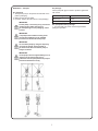
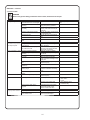
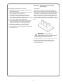
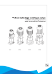
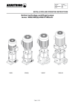
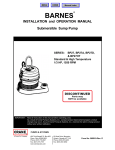
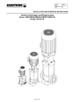
1
Manual Index
INSTALLATION AND OPERATION MANUAL
BPV Pumps
Series: BPV, BPV85, BPLHS
IMPORTANT!
A Crane Co. Company
Read all instructions in this manual before operating pump.
As a result of Crane Pumps & Systems, Inc., constant product improvement program,
product changes may occur. As such Crane Pumps & Systems reserves the right to
change product without prior written notification.
420 Third Street
Piqua, Ohio 45356
Phone: (937) 778-8947
Fax: (937) 773-7157
www.cranepumps.com
83 West Drive, Bramton
Ontario, Canada L6T 2J6
Phone: (905) 457-6223
Fax: (905) 457-2650
Form No. 127906-Rev. C
SAFETY FIRST!
Please Read This Before Installing Or Operating Pump. This
information is provided for SAFETY and to PREVENT EQUIPMENT
PROBLEMS. To help recognize this information, observe the
following symbols:
CAUTION ! Do not block or restrict discharge hose, as
discharge hose may whip under pressure.
IMPORTANT! Warning about hazards that can result
in personal injury orIndicates factors concerned with
assembly, installation, operation, or maintenance which
could result in damage to the machine or equipment if
ignored.
WARNING ! Do not wear loose clothing that may
become entangled in moving parts.
WARNING ! Keep clear of suction and discharge
openings. DO NOT insert fingers in pump with power
connected.
CAUTION! Warning about hazards that can or will cause minor
personal injury or property damage if ignored. Used with symbols
below.
Always wear eye protection when working on pumps.
WARNING! Warns about hazards that can or will cause serious
personal injury, death, or major property damage if ignored. Used
with symbols below.
Hazardous fluids can
cause fire or explosions, burnes or death
could result.
Biohazard can cause
serious personal injury.
Rotating machinery
Amputation or severe
laceration can result.
Make sure lifting handles are securely fastened each
time before lifting. DO NOT operate pump without safety
devices in place. Always replace safety devices that
have been removed during service or repair. Secure the
pump in its operating position so it can not tip over, fall
or slide.
Extremely hot - Severe burns
can occur on contact.
Hazardous fluids under pressure, eruptions or explosions
could cause personal injury
or property damage.
DO NOT exceed manufacturers recommendation for
maximum performance, as this could cause the motor
to overheat.
Hazardous voltage can
shock, burn or cause death.
DO NOT remove cord and strain relief. DO NOT connect
conduit to pump.
Only qualified personnel should install, operate and repair
pump. Any wiring of pumps should be performed by a qualified
electrician.
WARNING ! Cable should be protected at all times to
avoid punctures, cut, bruises and abrasions. Inspect
frequently. Never handle connected power cords with
wet hands.
WARNING ! To reduce risk of electrical shock, pumps and
control panels must be properly grounded in accordance
with the National Electric Code (NEC) or the Canadian
Electrical Code (CEC) and all applicable state, province,
local codes and ordinances. Improper grounding voids
warranty.
WARNING ! To reduce risk of electrical shock, all wiring
and junction connections should be made per the NEC
or CEC and applicable state or province and local
codes. Requirements may vary depending on usage
and location.
WARNING! To reduce risk of electrical shock, always
disconnect the pump from the power source before
handling or servicing. Lock out power and tag.
WARNING! Pumps are not approved for use in
swimming pools, recreational water installations
decorative fountains or any installation where human
contact with the pumped fluid is common.
WARNING! Operation against a closed
discharge valve will cause premature bearing
and seal failure on any pump, and on end
suction and self priming pump the heat build
may cause the generation of steam with resulting dangerous
pressures. It is recommended that a high case temperature
switch or pressure relief valve be installed on the pump body.
WARNING! Products returned must be cleaned,
sanitized, or decontaminated as necessary prior
to shipment, to insure that employees will not be
exposed to health hazards in handling said material. All
Applicable Laws And Regulations Shall Apply.
Bronze/brass and bronze/brass fitted pumps may
contain lead levels higher than considered safe for
potable water systems. Lead is known to cause cancer
and birth defects or other reproductive harm. Various
government agencies have determined that leaded
copper alloys should not be used in potable water
applications. For non-leaded copper alloy materials of
construction, please contact factory.
CAUTION ! Never operate a pump with a plug-in type
power cord without a ground fault circuit interrupter.
CAUTION ! Pumps build up heat and pressure
during operation-allow time for pumps to cool
before handling or servicing.
Crane Pumps & Systems is not responsible for losses,
injury, or death resulting from a failure to observe
these safety precautions, misuse or abuse of pumps or
equipment.
WARNING ! Do not pump hazardous materials
(flammable, caustic, etc.) unless the pump is specifically
designed and designated to handle them.
Other brand and product names are trademarks or registered trademarks of their respective holders.
®Burks is a registered trademark of Crane Pumps & Systems, Inc.
1998, 2001, 2003, 1/2006, 9/06
2
Alteration Rights Reserved
SECTION: A - Manual Introduction
A-1) Preface:
This manual contains important information for reliable
proper and efficient operation. Compliance with the
operating instructions is of vital importance to ensure
reliability and a long service life of the product and to avoid
any risks.
ATTENTION
Is used to introduce safety instructions
whose non-observance may lead to damage
to the product and its functions.
ENVIRONMENTAL INSTRUCTION
Remarks with respect to the environment
The first chapters contain information about this manual
and safety in general. The following chapters provide
information about normal use, installation, maintenance
and repairs of the product. The annexes contain the
technical data, the parts drawings and the declaration(s) of
conformity.
• Make yourself familiar with the content.
• Accurately follow the directions and instructions.
• Never change the sequence of the operations to be
carried out.
• Keep this manual or a copy of it together with the
logbook in a fixed place near the product which can be
accessed by all personnel.
A-2) Icons and symbols:
In this manual and in all accompanying documentation the
following icons and symbols are used.
WARNING
Danger of electric Voltage. Safety sign
according to IEC 417 - 5036.
IMPORTANT
Operations or procedures, if carried out
without caution, may cause personal injury
or damage to the product. General hazard
sign according to ISO 7000-0434.
3
SECTION: B - Identification, service and technical
support
B-1) Preface:
The name plate indicates the type series / size, main
operating data and identification number. Please quote this
information (first two lines*) in all queries, repeat orders
and particularly when ordering spare parts. If you need any
additional information or instructions exceeding the scope
of this manual or in case of damage please contact BPPumps’s nearest customer service center.
The following address data are available for service and
technical support:
Crane Pumps & Systems
service department
420 Third Street
Piqua, Ohio 45356
Tel: +1 937 7732442
Fax: +1 800 3287573
Internet: www.cranepumps.com
B-2) Nominal current:
The maximum allowable current of the motor is mentioned
as I.max. on the motor plate. This maximum allowable
current shows the maximum working range of the motor
and can be used to protect the motor.
IMPORTANT
Be careful in using it this way, because, not
only the motor, but also the pump has to be
protected in its application.
Indication
BPV
Seq. Nr
Ca / Sic / EPDM
PN
Q
H
n
Meaning
Pump type *
Sequence number *
Rotating part mechanical seal (Carbon) *
Stationary part mechanical seal (Siliconcarbide) *
Static sealing, O-Rings (EPDM) *
Pressure class (flange) connection *
Nominal capacity (see Q/H curve above)
Nominal head (see Q/H curve above)
Nominal rotation speed
4-40
Ca
Sic
EPDM
10
GPM
PSI
1/min
On the pump plate (sleeve sticker) this “pump current at
400 Volts” will be mentioned as I nom, and can be used
to pre-set the motor protection switch to protect the pump/
motor combination.
This current value can also be used to determine the
proper electrical equipment such as variable frequency
drive, main switch, wiring diameter etc.
B-3) Supplementary documentation:
Apart from the manual, the documentation given below is
also available.
4
SECTION: C - Safety and environment
C-1) General:
This BP Pumps product has been developed using stateof-the-art technology. It is manufactured with utmost care
and subject to continuous quality control. BP Pumps does
not accept any liability for damage and injury caused
by not observing the directions and instructions in this
manual. This also applies in cases of carelessness during
the installation procedure, use and maintenance of the
product.
ATTENTION
Make sure that the product operates within
its working range. Only then the product
performance is guaranteed.
C-3.1) Labels on the product
The icons, warnings and instructions applied to the product
are part of the safety provisions. The labels may not be
removed or covered. Labels must remain legible during
the entire life of the product. Replace damaged labels
immediately.
Non-compliance with safety instructions can jeopardize the
safety of personnel, the environment and the product itself.
Non-compliance with these safety instructions will also
lead to forfeiture of any and all rights to claim for damages.
C-4) Safety Precautions:
C-4.1) During normal use:
• Contact the local electricity company for questions
about the power supply.
• Shield parts, that can become hot in such a way, that
direct contact is impossible.
• When applicable, always place undeformed coupling
protection plates to protect the coupling, before putting
the pump into use. Make sure that the coupling
protection plates are never in contact with the
running coupling.
• Always close the terminal box on the pump.
For example, in particular non-compliance can result in:
• failure of important processes
• failure of prescribed performance
• injury
• hazard
• explosions.
Depending on specific activities, extra safety measures
may be required. Contact BP Pumps if a potential danger
arises during use.
ATTENTION
The owner of the product is responsible
for compliance with the local safety
regulations and internal company guidelines.
C-4.2) During installation, maintenance and repair:
Only authorized personnel may install, maintain and
inspect the product and repair electrical components.
Observe the local safety regulations.
ATTENTION
Not only must the general safety instructions
laid down in this chapter on “Safety” be
compiled with, but also the safety
instructions outlined under specific
headings.
WARNING
Always disconnect the energy supply to the
product first, before installation, maintenance
and repairs. Secure this disconnection.
IMPORTANT
Surfaces of a pump can be hot, after
continuous operation.
C-2) Users:
All personnel involved in the operation, maintenance,
inspection and installation of the product must be
fully qualified to carry out the work involved. Personal
responsibilities, competence and supervision must be
clearly defined by the operator. If the personnel in question
is not already in possession of the required know-how,
appropriate training and instruction must be provided. If
required, the operator may commission the manufacturer
/ supplier to take care of such training. In addition, the
operator is responsible for ensuring that the contents
of the operating instructions are fully understood by the
responsible personnel.
IMPORTANT
Make sure that no one can be near rotating
components when starting a pump.
IMPORTANT
Handle a pump with dangerous liquids with
the utmost care. Avoid danger for persons or
the environment when repairing
leakages, draining liquids and venting. it is
strongly recommended to place a relief barge
under the pump.
C-3) Safety Provisions:
The product has been designed with the greatest possible
care. Original parts and accessories meet the safety
regulations. Modifications in the construction or the use of
non-original parts may lead to a safety risk.
IMPORTANT
Immediately following completion of the
work, all safety-relevant and protective
devices must be re-installed and/or
re-activated.
5
SECTION: D - Intended Use
IMPORTANT
Please observe all instructions set out in the
chapter “Commissioning/Start-up” before
returning the product to servie.
D-1) Intended use:
The pumps BPV(S), BPVCF and BPLHS are suitable to
transport and increase the pressure of cold and hot water
without wear to parts within the indicated working range.
The transport of liquids with a different viscosity or density
than water is possible as well. For this a motor with an
adjusted power is used. Ask BP Pumps or your distributor
for advice.
C-5) Environmental aspects:
C-5.1) General:
The products of BP Pumps are designed to function in
an environmentally friendly way during their entire life.
Therefore, when applicable, always use biodegradable
lubricants for maintenance.
Any other or further use of the pump is not in conformity
with its intended use. BP Pumps does not accept any
liability for any damage or injury that results from this.
The pump is produced in accordance with the current
standards and guidelines. Use the pump only in a perfect
technical state, in conformance with the intended use
described below.
ENVIRONMENTAL INSTRUCTION
Always act according to the laws, by-laws
regulations and instructions with respect to
health, safety and the environment.
The intended use as laid down in EN 12100-1 is the use
for which the technical product is intended according to
the specifications of the manufacturer. The use of the
product has been described in the sales brochure and in
the user manual. When in doubt the product must be used
as becomes evident from its construction, version and
function.
C-5.2) Dismantling:
Dismantle the product and dispose of it in an
environmentally friendly way. The owner is responsible for
this.
ENVIRONMENTAL INSTRUCTION
Ask at the local government about the reuse or the environmentally friendly
processing of discarded materials.
Overload Protection: All motors must be installed with
magnetic starter which provides full overload protection
on all legs. Failure to use correct starter and overloads will
void motor warranty.
6
SECTION: E - Transport
E-2) Storage:
Fill the pump with glycol in order to protect it against the
risk of frost.
E-1) Transport:
1. Transport the pump in the position as indicated on the
pallet or packaging.
2. Make sure the pump is stable.
3. If present, observe the instructions on the packaging.
Storage
IMPORTANT
Lift the pump, if necessary using a hoist and
suitable slings. Attach the slings to
the transport lugs on the packaging, where
present.
tambient (ºC)
-10/40
max. rel. humidity (%)
80% at 20ºC not condensing
E-2.1) Inspection during storage:
1. Turn the shaft every three months and just before
putting into operation.
IMPORTANT
The pump must be lifted according to the
current hoist guidelines. Only qualified
personnel are allowed to lift the pump.
IMPORTANT
Do not lift the pump by using the frequency
converter (if placed), electrical parts or
the motor cover. Be sure that the pump is
always in balance.
IMPORTANT
All the pumps will turn approximately 2 to 15
degrees. Do not remove the lever or
protection from the pump before the pump is
placed and mounted correctly.
7
SECTION: F - Installation
F-1) Setting up the pump:
Allowable moment BPVCF
Allowable forces BPVCF
DN
inches
Fx
Force (kN)
Fy
Fz
Σ F
BPVCF 2
0.98
36
6.8
10.4
38.1
BPVCF 4
1.26
38
7.2
11
40.2
BPVCF 10
1.58
45
18
20
52.4
BPVCF 18
1.97
70
25
23
77.8
BPVCF 32
2.56
54
25
44
74
BPVCF 45
3.15
48
17
31
59.6
BPVCF 65
3.94
60
21
33
71.6
DN
inches
Mx
My
Mz
Σ M
BPVCF 2
0.98
700
800
1200
1600
1600
BPVCF 4
1.26
700
800
1200
BPVCF 10
1.58
1100
1000
2600
3000
BPVCF 18
1.97
2200
1300
2600
3600
BPVCF 32
2.56
2300
1700
2000
3500
BPVCF 45
3.15
2700
2700
2300
4500
BPVCF 65
3.94
3300
3600
3000
5700
ATTENTION
The values mentioned in the tables above
are given for the point at which a maximal
tension of between 200 and 205 MPa occurs.
It is assumed that the 3 forces or
the 3 moments as given in the drawing below
occur simultaneously.
ATTENTION
Make sure that the pump connections are
stress-less installed (e.g. no heavy load on
the inlet and outlet connections).
It is to be advised to use pipe-compensators,
see drawing above. Only on the
condition that the pump is provided
with a reinforced cast casing, model
BPVCF, the top/down force on the flanges
can be in accordance with the table below.
Type
Moment (Nm)
Type
8
ATTENTION
Pumps that do not stand steady or stable on
their own, should be mounted on a rigid
and stable base.
F-1.2) Install bypass:
Install a bypass if the pump operates against a closed
valve. The required capacity of the bypass is at least
10% of the optimum volume flow. At high operating
temperatures a higher volume flow is required. Refer to the
table “Minimum volume flows” in the paragraph “Working
range”
ATTENTION
Place the pump there where there is the
lowest risk for noise nuisance.
F-2) Mounting a motor on the pump:
1. Place and install the pump on a level, stable surface in
a dry and frost-proof room.
2. Make sure that sufficient air can reach the cooling fan
of the motor. For this purpose the free space above the
cooling fan should be at least ¼ of the diameter of the
fan cover air intake.
3. Install the pump with counter flanges. Pumps with nonstandardised connections; counter flanges are delivered
separately.
4. Install a valve on the supply and on the delivery
connection of the pump.
5. If there is a chance that when the pump is standing still
the medium can flow back, it is advised to install a nonreturn valve.
6. Make sure that the inlet of the pump is never clogged.
The motor has to conform to the following conditions:
• Increased power output (to limit the standard installed
motor power)
• Reinforced bearing at driven end (to withstand the axial
force)
• Fixed bearing at driven end (to minimize the axial play)
• Smooth shaft, no key lock (to improve the coupling grip
and to improve the motor balance)
F-1.1) Indicators:
The advised bearings per motor type are:
ATTENTION
It is to be advised to use a special designed
BP Pumps motor. Before installing an other
brand/standard IEC-norm motor, BP Pumps
has to be consulted to judge the applicability.
(HP)
The arrow (A) on the pump foot indicates the flow direction
of the liquid. The arrow (B) on the top bracket indicates the
rotating direction of the motor.
9
Axial Bearing
(HP)
Co-axial Bearing
0.50
6203-2RS
7.50
6308-2Z-C3
0.75
6203-2RS
10.00
6308-2Z-C3
1.00
6204-2RS
15.00
7309-BEP
1.50
6204-2RS
20.00
7309-BEP
2.00
6305-2Z-C3
25.00
7309-BEP
3.00
6305-2Z-C3
30.00
7311-BEP
5.00
6306-2Z-C3
40.00
7312-BEP
50.00
7312-BEP
F-2.1) Install the motor on pumps, supplied without
motor, with a standard mechanical seal:
6. Lift the pump assembly to the maximum upwards
position put a tyre lever under the coupling.
ATTENTION
For motors of 15HP or higher, block the
rotor when adjustments are made to
the coupling. This ensures that the rotor will
not come out of its bearings.
IMPORTANT
Correct seal tension max, -1mm lower than
the maximum upwards position!
1. Remove the “transport fixation assembly” together
with the coupling guards (681) and the coupling shells
(862). For some models the coupling shells are
delivered separately.
2. Thoroughly clean the motor stool (341), the shaft (210),
the coupling shells (862) and the motor shaft.
3. Loosely fasten the coupling shells (862) with the
coupling pin (560) on the shaft (210). Use the hexagon
socket head cap screw (914.01) and the nut (920.01)
for this purpose. (When the pump is equipped with a
steel coupling, never use the same coupling twice but
order a new one).
4. Place the motor on the motor stool (341).
5. Tighten the lower bolts of the coupling shells (862)
so far that the coupling slightly clamps around the
motor shaft.
7. Position the pump assembly 1mm lower than the
maximum upwards position as mentioned earlier.
8. Fully tighten the couplings to the correct torque (See
“Torques” in the annexes). Make sure that the gaps
between the couplings are equally divided on both
sides (see drawing).
9. Attach the coupling guards (681) with the hexagon
head bolts (901.01) to the motor stool (341).
10. Connect the electricity supply to the motor.
10
F-2.2) Installing the motor on pumps, supplied without
motor, with a cartridge seal:
ATTENTION
For motors of 15HP or higher, block the rotor
when adjustments are made to the coupling.
This ensures that the rotor will not come out
of its bearings.
IMPORTANT
Correct seal tension max. -1mm lower than
the maximum upwards position!
10. Position the pump assembly 1mm lower than the
maximum upwards position as mentioned earlier.
11. Fully tighten the couplings to the correct torque (see
“Torques” in the annexes). Make sure that the gaps
between the couplings are equally divided on both
sides (see drawing).
1. Remove the “transport fixation assembly” together
with the coupling guards (681) and the coupling shells
(862). For some models the coupling shells are
delivered separately.
2. Thoroughly clean the motor stool (341), shaft (210),
coupling shells (862) and the motor shaft.
3. Loosely fasten the coupling shells (862) with the
coupling pin (560) on the shaft (210). Use the hexagon
socket head cap screw (914.01) and the nut (920.01)
for this purpose. (When the pump is equipped with a
steel coupling, never use the same coupling twice but
order a new one).
4. Place the motor on the motor stool (341).
5. Loosen the three cartridge grub screws (904) one turn.
6. Push the hydraulic pump assembly in the lowest
position.
7. Tighten the three cartridge bolts (904) firmly to the shaft.
8. Tighten the lower bolts of the coupling shells (862) so
that the coupling clamps slightly around the motor shaft.
9. Lift the pump assembly to the maximum upwards
position and mark the shaft. For this purpose put a tyre
lever under the coupling
12. Install the coupling guards (681) with the hexagon
head bolts (901.01) to the motor stool (341).
13. Electrically connect the motor.
11
F-4) Commissioning:
IMPORTANT
The pump must not be switched on when it is
not completely filled up.
ATTENTION
Seen from the top of the motor the pump
should rotate clockwise (B) See G-1 Setting
up the pump 145. In case of a 3-phase motor
the rotating direction can be changed by
exchanging two of the three phase wires.
F-4.1) In an open or closed circuit with sufficient
supply pressure:
1. Partly loosen the drain lug (A). For BPVE, BPVCF, and
BPLHS the drain plug must be fully removed.
2. Remove the fill plug (B) from the top bracket.
3. Block the entry of the drain plug on the outside of the
pump foot.
4. Close the outlet shut-off valve.
5. Fill the pump housing to the maximum through the fill
plug with the liquid that is to be pumped.
6. Screw the drain plug into the pump foot.
7. Insert the fill plug in the top bracket.
8. Check the rotational direction of the pump.
9. Open the outlet shut-off valve.
F-4.3) After an extended period of non-operation or
storage:
During first start-up, be sure to check the mechanical seals
for leakage due to seizure or dehydration of he lubricating
film. if this is the case, please proceed as follows:
1. Turn shaft manually or;
2. Start up the pump, then open and close the outlet shutoff valve quickly during operation.
3. Check if the mechanical seal is still leaking.
If the shaft is still leaking:
1. Disassemble the mechanical seal.
2. Thoroughly clean and degrees the running surfaces.
3. Assemble the mechanical seal again ad retry start-up.
If this doesn’t solve the shaft leakage, replacement of the
mechanical seal is necessary.
1. Close the suction shut-off valve (A) and the outlet shutoff valve (B).
2. Open the fill plug (C).
3. Gradually open the suction shut-off valve until the liquid
flows from the fill plug (C).
4. Close the fill plug.
5. Fully open the suction shut-off valve.
6. Check the rotational direction of the pump.
7. Fully open the outlet shut-off valve.
SECTION: G - Operation:
G-1) Operation:
The pump is controlled externally and therefore does not
need any operation guidance.
F-4.2) In an open circuit with a liquid level lower than
the pump:
12
SECTION: H - Maintenance:
H-3) Maintaining the pump for an extended period of
non-operation:
Turn the shaft every three months. This protects the sales
from seizure.
H-1) Introduction:
WARNING
Observe the general safety precautions for
installation, maintenance and repair.
Protect the pump against if there is a risk of frost. Proceed
as follows:
Regular maintenance is necessary for the correct
operation a pump. For maintenance of the pump, please
contact your supplier.
1.
2.
3.
4.
H-2) Lubrication:
Standard motors, with a maximum power of 10HP, are
provided with maintenance free sealed bearings.
Close all pump valves.
Drain
Remove
Open
H-4) Replace BPVE non-return valve:
Motors with lubricating nipples must be lubricated after
2000 hours. If the pump works under extreme conditions,
such as vibrations and high temperatures, the motors
must be lubricated more often.
Use a lithium based -30ºC/160ºC bearing lubricant (about
15 gram).
When the pump is delivered without a motor and fitted
with an other brand or the standard motor is replaced
by an other brand than BP Pumps, please consult the
maintenance instructions of the motor supplier.
To replace the non-return valve of the pump types BPVE,
proceed as follows:
1.
2.
3.
4.
13
Use a pair of pliers to remove the non-return valve.
Remove the O-ring.
Install a new O-ring.
Install the new non-return valve.
SECTION: J - Failures:
J-1) Failure table:
WARNING
Observe the general safety precautions before install, maintenance and repair.
Problem
Leakage along the shaft
Possible Cause
Running surfaces of the
mechanical seal worn or damaged
New pump: seal stuck due to
assembly
Mechanical seal mounted
incorrectly
Elastomers affected by medium
Pressure too high
Shaft worn
Pump has been operating without
water
Leakage along the
O-ring worn
shroud at the top bracket O-ring not resistant to the medium
or at the pump foot
to be pumped
Too much tension on the pump
foot; it becomes oval
Pump is vibrating or noisy Coupling mounted incorrectly
Faulty settling of the hydraulic
assembly
There is no water in the pump
No supply
Bearings of pump and/or motor
worn
Available NPSH too low
(cavitation)
Pump does not operate in its
working range
Malfunction
Pump does not start
Pump is standing on an uneven
surface
Internal blockage in the pump
Possible Solution
Replace the mechanical seal
Open and close the outlet shut-off
valve quickly during operation
Install the mechanical seal
correctly. Use water and soap as
a lubricant
Use the right rubber compound for
the mechanical seal
Use the right type of mechanical
seal
Replace shaft and mechanical seal
Replace the mechanical seal
Replace the O-ring
Replace O-ring by an O-ring with
better resistance
Decrease tension on piping
Mount the pump foot tensionless
Support the connections
Install the coupling in parallel
Adjust the assembly according to
the manual
Fill and vent the pump
Make sure there is sufficient
supply. Check for blockages in the
supply line
Have the bearings replaced by a
certified company
Improve suction condition
Select another pump or adjust the
system to work within its working
range
Level the surface
Have the pump inspected by a
certified company
No voltage on the terminal clamps Check the power supply
Check the motor safety relay
Thermal motor safety switch
triggered
The motor is running, but The motor shaft has been broken
the pump does not work The pump shaft has been broken
The coupling between pump and
motor shaft is loose
Checkpoints
Check the pump for dirt-abrasive
parts
Reset the thermal motor-safety.
Contact the supplier, if this
problem occurs more often.
Contact the supplier
Contact the supplier
Tighten the connecting screws to
the recommended torque
14
•
•
•
•
•
Circuit
Main Switch
Fuses
Earth leakage switch
Protective relay
Problem
Pump supplies
insufficient capacity and/
or pressure
Possible Cause
Outlet and/or inlet shut-off valve
is closed
There is air in the pump
The suction pressure is insufficient
Pump rotates in the wrong
direction
The suction line has not been
vented
Air bubble in the suction line
Pump sucks air because of
leakage in the suction line
Too little water consumption so air
bubbles clog up in the pump
The diameter of the suction line is
too small
Capacity of water meter in the
supply line is too small
Foot valve blocked
The impeller or the diffuser is
blocked
O-ring between impeller and
diffuser is gone
O-ring not resistant to the medium
to be pumped
Possible Solution
Open both shut-off valves
Vent the pump
Increase the suction pressure
Change over L1 and L2 of the
three phase supply
Vent the suction line
Install the suction line with pump
end higher than the other end
Repair the leakage
Make sure the consumption
increases or use a smaller pump
Increase the diameter of the
suction line
Increase the capacity of the water
meter
Clean the foot valve
Clean the inside of the pump
Replace the O-rings
Replace O-ring by an O-ring with
better resistance
15
Checkpoints
SECTION: K - Spare Parts:
K-1) Recommended spare parts BPV(S)(C)(F)(V):
This recommendation includes all parts required to
rebuild a disassembled pump with replacement of all
stage casings/diffusers with bearing (108.02/171.02),
bearing sleeves (529) and all sealings. Major parts such
as impellers, diffusers, shafts, castings etc. are normally
not required for overhaul but are of course available on
request.
The number of parts needed for a specific type of pump
can be found in either the Bill of Materials or the Spare
Parts List. The position number refers to the cut away
drawing.
* Mechanical Seal Kits include ALL gaskets necessary for
seal replacement.
BPV(S)(C)(F) 2/4
Quantity
2
2
2
2
2
B
B
N
N
1
1
B
1
1
1
1
Item No.
412.01
108.02
412.03
* 433
529
525.04
920.02
930
Description
O-ring EPDM (Circular groove)
O-ring EPDM (Rectangular groove)
O-ring EPDM E425 (Rectangular groove)
O-ring Viton (Circular groove)
O-ring Viton (Rectangular groove)
Stage casing with ceramic bearing BPV, BPVC 2/4
Stage casing with ceramic bearing BPVS 2/4
O-ring EPDM
O-ring Viton
Mechanical bellow seal BPV 2/4, EPDM
Mechanical bellow seal BPVS 2/4, Viton
Bearing Sleeve d=12mm
Spacer sleeve end BPV(S)(E) 2/4
Lock-nut with non metallic insert A2 (BPV)
Lock-nut with non metallic insert A4 (BPVS)
Safety device A4 Nord-lock M10
Part No.
18030201
19120200
19120205
18030209
19120208
18030260
18030212
18030211
18030212
127932
127933
18020377
13030374
76052010
76052011
76940110
Description
O-ring EPDM (Circular groove)
O-ring EPDM (Rectangular groove)
O-ring EPDM E425 (Rectangular groove)
O-ring Viton (Circular groove)
O-ring Viton (Rectangular groove)
Stage casing with ceramic bearing BPV 10
Stage casing with ceramic bearing BPVS 10
Stage casing with ceramic bearing BPV 18
Stage casing with ceramic bearing BPVS 18
O-ring EPDM BPV 10
O-ring Viton BPVS 10
O-ring EPDM BPV 18
O-ring Viton BPVS 18
Mechanical bellow seal BPV, BPVC 10/18, EPDM
Mechanical bellow seal BPVS 10/18, Viton
Bearing sleeve d=16mm
Spacer sleeve end BPV(S) 10/18
Lock-nut with non metallic insert A2 (BPV)
Lock-nut with non metallic insert A4 (BPVS)
Safety device Nord-lock M10
Part No.
18110200
18110201
18110202
18110208
18110209
18112260
13112260
18192260
13192260
18110211
18110212
18190211
18190212
127934
127935
18100377
13110374
76052010
76052011
76940110
BPV(S)(C)(F)10/18
Quantity
2
2
2
2
2
B
B
B
B
N
N
N
N
1
1
B
1
1
1
1
Item No.
412.01
108.02
412.03
* 433
529
525.04
920.02
930
16
BPV(S)(C)(F) 32-10, 32-20, 45-10 with standard mechanical seal
Quantity
B
B
2
2
2
1
1
B
B
B
B
B
1
1
1
1
Item No.
171.02
412.01
* 433
525.01
529
525.03
525.04
920.02
930
Description
Diffuser with ceramic bearing BPVF 32/45
Diffuser with ceramic bearing BPVSF 32/45
O-ring EPDM
O-ring EPDM E425 (Rectangular groove)
O-ring Viton
Mechanical bellow seal BPV 32/45, EPDM
Mechanical bellow seal BPVS 32/45, Viton
Spacer sleeve short BPVF 32/45
Spacer sleeve short BPVSF 32/45
Bearing Sleeve d=12mm
Spacer sleeve long BPVF 32/45
Spacer sleeve long BPVSF 32/45
Spacer sleeve end BPV(S) 32/45/65
Lock-nut with non metallic insert A2 (BPV)
Lock-nut with non metallic insert A4 (BPVS)
Safety device Nord-lock M12
Part No.
18330260
13330260
18660200
18660201
18660208
127936
127937
18330379
13330379
18320377
18330375
13330375
13330374
76052012
76052013
76940112
BPV(S)(C)(F) 32-30, 32-40, 32-50, 32-60, 32-70, 32-80, 32-90, 45-20, 45-30, 45-40, 45-50, 45-60
with mechanical cartridge seal
Quantity
1
1
1
1
1
1
2
2
2
B
B
1
1
B
B
B
B
B
1
1
1
1
Item No.
412.05
412.06
412.01
171.02
* 433
525.01
529
525.03
525.04
920.02
930
Description
O-ring EPDM
O-ring EPDM E425
O-ring Viton
O-ring EPDM
O-ring EPDM E425
O-ring Viton
O-ring EPDM
O-ring EPDM E425 (Rectangular groove)
O-ring Viton
Diffuser with ceramic bearing BPVF 65
Diffuser with ceramic bearing BPVSF 65
Mechanical bellow seal BPVF 32/45/65, EPDM
Mechanical bellow seal BPVSF 32/45/65, Viton
Spacer sleeve short BPVF 65
Spacer sleeve short BPVSF 65
Bearing sleeve d=22mm
Spacer sleeve long BPVF 65
Spacer sleeve long BPVSF 65
Spacer sleeve end BPV(S) 32/45/65
Lock-nut with non metallic insert A2 (BPV)
Lock-nut with non metallic insert A4 (BPVS)
Safety device A4 Nord-lock M12
17
Part No.
18660171
18660175
18660172
18660170
18660179
18660178
18660200
18660201
18660208
18660260
13660260
127938
127939
18660379
13660379
18320377
18660375
13660375
13330374
76052012
76052013
76940112
BPV(S)(C)(F) 65 with mechanical cartridge seal
Quantity
1
1
1
1
1
1
2
2
2
B
B
1
1
B
B
B
B
B
1
1
1
1
Item No.
412.05
412.06
412.01
171.02
* 433
525.01
529
525.03
525.04
920.02
930
Description
O-Ring EPDM
O-Ring EPDM E425
O-Ring Viton
O-Ring EPDM
O-Ring EPDM E425
O-Ring Viton
O-Ring EPDM
O-Ring EPDM E425
O-Ring Viton
Diffuser with ceramic bearing BPVF 65
Diffuser with ceramic bearing BPVSF 65
Mechanical bellow seal BPVF 24/32/45/65, EPDM
Mechanical bellow seal BPVF 24/32/45/65, Viton
Spacer sleeve short BPVF 65
Spacer sleeve short BPVSF 65
Bearing sleeve d-22mm
Spacer sleeve long BPVF 65
Spacer sleeve long BPVSF 65
Spacer sleeve end BPV(S) 24/32/45/65
Lock-nut with non metallic insert A2 (BPV)
Lock-nut with non metallic insert A4 (BPVS)
Safety device A4 Nord-lock M12
Part No.
18660171
18660175
18660172
18660170
18660179
18660178
18660200
18660201
18660208
18660260
13660260
127938
127939
18660379
13660379
18320377
18660375
13660375
13330374
76052012
76052013
76940112
BPV(S)(C)(F) 85 with mechanical cartridge seal
Quantity
1
1
Item No.
* 433
Description
Mechanical Seal BPVF
Mechanical Seal BPVSF
Part No.
127940
127941
Consult factory for additional part numbers if needed
BPLHS 6
Quantity
1
2
N
B
B
Item No.
* 433
412.01
412.03
108.02
529
Description
Mechanical seal 40 bar
O-ring, for sleeve
O-ring, for diffuser
Stage casing with ceramic bearing
Bearing sleeve
18
Part No.
19390182
18060200
18060207
13400260
18100377
SECTION: L - Service Tools:
L-1) Service tool kits:
Pump de-aeration kit
Vacuum de-aeration kit:
Hand pump
Clamp
Hose pipe 25mm
Hose connection 1” x 25mm
Adapter piece 1” x 22mm
Pipe 22mm
Knee coupling ¾” x 22mm
Reducing ring ¾” x ½mm
Reducing nipple ¼” x ½”
Quantity
1
2
1 (m)
1
1
20 (cm)
1
1
1
Pump (dis)assembling kit
Coupling Adjustment
Socket head wrench screwdriver 3mm
T-grip socket head wrench 5mm
T-grip socket head wrench 6mm
T-grip socket head wrench 8mm
Tyre lever 300
Socket wrench screw driver
Quantity
1
1
1
1
1
1
De-aeration and draining
Wrench 17mm
Quantity
1
Motor Mounting
Wrench 10mm
Wrench 13mm
Wrench 19mm
Wrench 22mm
Wrench 24mm
Quantity
1
1
1
1
1
(Dis) assembling of hydraulic parts
Mounting plate
Davel pin 5 x 70mm
Quantity
1
1
Torque wrench
Torque wrench 10-100 Nm
Socket 13mm
Socket 17mm
Socket 24mm
Quantity
1
1
1
1
Mounting plate
Mounting plate dimensions
19
SECTION: M - Condensed Repair Instructions:
M-1) General:
These instructions concern the repairs which can be
handled by a local service engineer. Please note that
during all mentioned repairs all precautions are to be taken
and the pump always has to be disconnected from the
electrical supply. The numbers mentioned after the parts
refer to the position numbers of these parts in the cut
away drawing of the pump concerned.
IMPORTANT
Never allow the pump to run dry
M-2) Replacement of standard mechanical seal
BPV(S):
1. Check if pump is drained and if not, drain it.
2. Remove the hexagon head bolts and coupling guards
(901.01, 681), disassemble the coupling shell (862) and
the pin (560), unscrew hexagon head bolts and washer
(901.02, 554.02) and take the motor (800) off the motor
stool (341).
3. Loosen the 4 nuts (920.03) crosswise and equally lift
the motor stool (341) and the cover (160) from
the upper stage casing (108.05/108.06/171.03) and
the pump-shroud (10-6). If necessary use a screwdriver
(flat and narrow) to remove the motor stool (341) from
the pump-shroud (10-6). Push the screwdriver in the
groove of the pump-shroud (10-6) and rotate it around
the edge of the motor stool (341). Repeat this action
several times until the two parts are separated.
4. Pull the rotating part of the mechanical seal (433)
from the shaft (210). Clean the shaft (210) and check
for damages.
5. Wet the shaft-end (210) with water or a soap solution.
Push the rotating part of the new mechanical seal (433)
on the shaft (210).
6. Remove the old static part of the mechanical seal (433)
from the cover (160) assembly. Wet the new part of the
mechanical seal (433) with water or a soap solution and
put it in the motor stool (341). Slide this cover (160) into
the motor stool (341) and over the mechanical seal.
7. Finish the pump assembly as described in xx.xx.x
Finishing the pump assembly all BPV(S)(C)(F) with
standard mechanical seal 195.
8. Install the motor (800) on the motor stool (341) and
assemble pin (560) and coupling shell (862) on the
shaft (210) as described in xx.xx.x BPV(S)(F)
2/4/10/18/32/45/65 with standard mechanical
seal 196.
9. De-aerate pump and pipe work. Check for the correct
rotation (clockwise). See xx.x Setting up the pump 145.
10. Test run the pump and retighten the tie-rods crosswire
and equally on torque.
M-3) Replacement of standard mechanical cartridge
seal BPV(S)F 32/45/65:
1. Carefully relieve any pressure in the pump.
2. Remove hexagon head bolts (901.01) and coupling
guard (681), disassemble the coupling shell (862) and
the pin (560)
3. Unscrew the three grub screws (904) partly and the four
hexagon socket head cap screws (914.01) completely.
4. Place a screwdriver between the seal cover (471) and
the motor stool (341) and lift the cartridge seal from the
shaft (210)
5. Unscrew the grub screws (904) completely and remove
the ring (500), if present the flat ring and the seal cover
(471), from the spacer sleeve cartridge (525.07).
6. Remove the old static part of the mechanical seal (433)
from the seal cover (471) with water or a soap solution
and place the new static part.
7. Remove the old rotating part of the mechanical seal
(433) from the spacer sleeve cartridge (525.07).
Clean the spacer sleeve cartridge (525.07) and check
for damages.
8. Wet the spacer sleeve cartridge (525.07) with water or
a soap solution and place the new rotating part.
9. Remove the O-rings (412.05, 412.06) from the spacer
sleeve cartridge (525.07) and the seal cover (471) and
replace them by new ones.
10. Slide the seal cover (471) on the spacer sleeve
cartridge (525.07) and the ring (500) and screw grub
screws (904) partly in. Do not replace the flat ring.
11. Wet the shaft (210) with water or a soap solution and
place the new cartridge seal.
12. Assemble pin (560) and coupling shells (862) on the
shaft (210) as described in xx.xx.x BPV(S)F
32/45/65 with mechanical cartridge seal 197.
13. De-aerate pump and pipe work. Check for the correct
rotation (clockwise). See xx.x Setting up the pump 145.
14. Test run the pump.
20
SECTION: N - Assembling and disassembling
BPV(S)(C)(F)(V):
M-4) Change of terminal box connection:
1. Disassemble the hexagon head bolts (901.01) and the
coupling guards (681).
2. Remove the bolts/screws (901.02/914.02) of the motor
and if necessary the electrical wiring.
3. Lift the motor (800) a little with a tyre lever placed
underneath the coupling shell (862). If this fails
disassemble the coupling as described in xx.x.x BPV(S)
F 32/45/65 with mechanical cartridge seal 197.
4. Turn the motor (800) into preferred position.
5. Fasten the bolts/screws (901.02/914.02) of the motor
crosswire and equally, if necessary reassemble the
coupling as described in xx.x.x BPV(S)F 32/45/65
with mechanical cartridge seal 197, reconnect the
electrical wiring and check rotation (clockwise).
6. Reassemble the coupling guard (681) and the hexagon
head bolts (901.01).
N-1) General:
The starting point of the following procedure is a pump
taken out of an installation. The hydraulic assembly of a
BPV(S) pump is to be assembled or disassembled with the
coupling side of the shaft directing downwards. A simple
aid for this method is a jaw bench, provided with tension
plates. For larger series a special mounting plate can be
used. The shaft (coupling side) is to be placed in the bush
and locked with a pin diameter 5mm through the coupling
hole.
IMPORTANT
Before starting the assembling or
disassembly, make sure the correct type of
O-rings and shroud are present!
For determination of the correct O-ring and shroud to be
used for the assembling and disassembling of the
BPV(S)(C)(F)(V), carefully select them using the
proceeding diagrams.
21
Selection O-ring and shroud BPV(S)2-4
Selection O-ring and shroud BPV(S)(F)(V) 10-18
22
N-2) Disassembling BPV(S):
1. Remove the coupling guards (681).
2. Remove motor bolts/screws (901.02/914.02) and
washers (554.02) and lift the motor (800) with a tyre
lever placed under the coupling shells (862) to loosen it
from the motor stool (341).
3. Remove hexagon socket head cap screws (914.01)
and nuts (920.01) from the coupling shells (862) and
take the coupling shells (862) and the pin (560) from the
shaft (210).
4. Remove the motor (800) from the motor stool (341).
5. Only for V(S)F 32/45/65 with cartridge seal:
thoroughly clean the top end of the shaft (210),
loosen the three grub screws (904) partly and remove
the four hexagon socket head cap screws (914.03),
place a screwdriver between the seal cover (471) and
the motor stool (341) and lift the cartridge seal from the
shaft (210).
6. Loosen the 4 nuts (920.03) fitted on the tie-bolts
(905) crosswire and equally, lift the motor stool (341)
and the cover (160) from the upper stage casing/
diffuser (108.05/108.06/171.03) and the pump-shroud
(10-6). If necessary use a screwdriver (flat and narrow)
to remove the motor stool (341) from the pump-shroud
(10-6). Push the screwdriver in the groove of the pumpshroud (10-6) and rotate it around the edge of the motor
stool (341). Repeat this action several times until the
two parts are separated.
7. Lift the pump shroud (10-6) from the pump casing (101).
8. Lift the hydraulic parts from the pump casing (101) by
means of a pin diameter 5mm through the coupling
pinhole at the top of the shaft (210).
9. Only for V(S) 2/4/10/18 and V(S)F 32/45/65 with
standard mechanical seal: Clean the top end of the
shaft (210) thoroughly before removing the rotating part
of the mechanical seal (433) from the shaft.
10. Place the shaft with the top end facing downwards
in a jaw bench or place and lock it into a shaft support
accessory.
11. Remove the lock nut with non metallic insert (920.02)
from the shaft (210) and take all hydraulic parts from
the shaft. It is recommended to number the different
parts in sequence of disassembling.
N-3) Assembling BPV(S):
A BPV(S) pump consists of the assembly of three subassemblies. First prepare the subassemblies before
commencing with the assembly. For the subassembly
of the pump casing see. Assembling the pump casing
BPV(S)(F) 2/4/10/18/32/45. Assembling the pump casing
BPV(S)F 65. Assembling the pump casing all BPVCF.
For all subassembly of the hydraulic parts. Assembling
the hydraulic parts BPV(S)(C)(F) 2/4/10/18. Assembling
the hydraulic parts BPV(S)(C)F 32/45. Assembling the
hydraulic parts BPV(S)(C)F 65. For the subassembly of
the motor stool assembly. Assembling the motor stool all
BPV(S)(C)(F) with standard mechanical seal. Assembling
the motor stool all BPV(S)(C)(F) with standard mechanical
seal. Finishing the pump assembly all BPV(S)(C)F with
mechanical cartridge seal. While reading the assembling
instruction you are well advised to have a copy available of
a cut away drawing and/or an exploded view of the pump.
N-3.1) Assembling the pump casing BPV(S)(F)
2/4/10/18/32/45:
1. Place the pump casing (101) on top of the base plate
(890). The hole for the screwed plug (903.02) should be
directed opposite to the arrow.
2. Slide the joint ring (411.03) on the screwed plug
(903.02).
3. Mount the screwed plug (903.02) into the pump casing
(101).
4. Insert the stage csing/disc (108.04/550) into the pump
casing (101) and wet the O-ring (412.01) with water or a
soap solution.
5. Check if stage casing/disc (108.04/550) is level with the
pump csing (101). If not tap gently with a rubber or plastic
hammer.
6. Mount 4 tie bolts (905) in the base plate (890).
For reassembly of the pump. Assembling BPV(S).
23
N-3.2) Assembling the pump casing BPV(S)(F) 65:
1. Place the pump casing (101) on top of the base plate
(890). The hole for the screwed plug (903.02) should be
directed towards the arrow.
2. Slide the O-ring (411.03) on the screwed plug (903.02).
3. Mount the screwed plug (903.02) into the pump casing
(101).
4. Insert the stage casing/disc (108.04/550) into the pump
casing (101) with the letter “T” upwards.
5. Check if the stage casing/disc (108.04/550) is level with
the pump casing (101). If not tap gently with a rubber or
plastic hammer.
6. Mount 4 tie bolts (905) in the base plate (890).
N-3.3) Assembling the pump casing all BPVCF:
1. Place the pump casing (101) on the table.
2. Slide the joint ring (411.03) on the socket head cap
screw (914.03).
3. Mount the socket head cap screw (914.03) into the
pump casing (101).
4. Insert the stage casing/disc (108.04/550) into the pump
casing (101) and wet the O-ring (412.01) with water or
a soap solution.
5. Check if stage casing/disc (108.04/550) is level with the
pump casing (101). If not tap gently with a rubber or
plastic hammer.
6. Mount 4 tie bolts (905) in the pump casing (101).
N-3.4) Assembling the hydraulic parts BPV(S)(C)(F)
2/4/10/18:
1. Place the shaft (210) with the top end facing
downwards, into a shaft support accessory or clamp the
top end in a jaw bench fitted with soft jaws.
2. Slide the spacer sleeve (525.05) on the shaft (210)
and lock it with the circlip (932). For BPV 2 and 4 the
circlip (932) is one part and for all other models the
circlip (932) should be completely covered by the
spacer sleeve (525.05). If necessary a piece of pipe,
slightly larger in diameter than the shaft (210), can be
used to apply a force to the spacer sleeve (525.05).
3. Slide the upper stage casing (108.05/108.06) on the
shaft (210). The end opening of the upper stage casing
(108.05/108.06) should be directed downwards. (For
V(S) 2/4/10/18-10 pumps, the upper stage casing
(108.06) is one without vanes).
4. Slide an impeller (230) on the shaft (210). the inlet of
the impeller (230) should be pointed upwards.
(For V(S) 2/4/10/18-10 pumps, the upper impeller is to
be replaced by a spacer ring). the top stage of the
pump is now assembled.
ATTENTION
Depending on the specific pump and
the number of stages that need to be
assembled the next step is to assemble
either a stage casing (108.01/108.03) or a
stage casing with ceramic bearing (108.02).
5. Check the bearing position number in chapter 33
Bearing positions 205 and check if this stage will need
a bearing.
6. When the next stage needs a bearing, first put a spacer
sleeve short (525.01) on the shaft followed by a bearing
sleeve (529). Before a diffuser with bearing can be
placed, the inside of the bearing must be greased with
acid free vaseline.
7. When the next stage does not need a bearing, only a
spacer sleeve long (525.03) has to be placed on
the shaft (210) (with the thin part of the spacer sleeve
long (525.03) up).
8. Place the stage casing (with ceramic bearing)
(108.02/108.03) on the shaft (210) with a rotating
movement followed by an impeller (230).
9. Repeat assembly until all impellers (230) are mounted.
10. Slide the spacer sleeve end (525.04) and the safety
device nord-lock (930) on the shaft (210). Make sure
you mate the similar sides of the safety nord-lock (930)
and the spacer sleeve end (525.04).
11. Lock the impeller (230), spacer sleeve (short/long/end/
bearing sleeve (525.01, 529, 525.03, and 525.04) and
spacer sleeve seal (525.05) with a new lock-nut
with non metallic insert (920.02). The maximum torque
is mentioned in xx.x Torques (all pump types) 204.
N-3.5) Assembling the hydraulic parts BPV(S)F 32/45:
1. Place that shaft (210) with the top end facing
downwards, into a shaft support accessory or clamp the
top end in a jaw bench fitted with soft jaws.
24
2. Slide the spacer sleeve seal (525.05) on the shaft (210)
and lock it with the circlip (932). The circlip (932)
should be completely covered by the spacer sleeve
seal (525.05). If necessary a piece of pipe, slightly
larger in diameter than the spacer sleeve seal (525.05).
11. Lock the impellers (230/230.01), spacer sleeve (short/
long/end) or bearing sleeve (525.01, 525.03, 525.04, or
529) and spacer sleeve seal (525.05) with a new locknut with non metallic insert (920.02). The maximum
torque is mentioned in xx.x Torques (all pump types)
204.
N-3.6) Assembling the hydraulic parts BPV(S)(C)F 65:
1. Place the shaft (210) with the top end facing
downwards, into a shaft support accessory or clamp the
top end in a jaw bench fitted with soft jaws.
2. Slide spacer sleeve seal (525.05) on the shaft (210) and
lock it with the circlip (932) (fig. 3, Appendix 1). The
circlip (932) should be completely covered by the
spacer sleeve seal (525.02). If necessary a piece of
pipe, slightly larger in diameter than the shaft (210), a
force can be applied to the spacer sleeve seal (525.05).
3. Assemble on a bench the sharp innerside of the upper
intermediate ring (509.02) to the discharge opening
of the diffuser (with ceramic bearing) (171.02 or 171.01)
and push it (in one piece) over the shaft (210) with
discharge opening downwards.
4. Slide an impeller (230) on the shaft (210). The inlet of
the impeller (230) should be pointed upwards. The top
stage of the pump is now assembled.
3. Assemble on a bench the upper intermediate ring
(509.02) to the discharge opening of the upper diffuser
(171.03) and push them (in one piece) over the shaft
(210) with the discharge facing opening downwards.
4. Slide an impeller (230/230.01 or 320.02) on the shaft
(210). The inlet of the impeller (230/230.01 or (230.02)
should point upwards. In case of a pump with a half
stage impeller (230.02), this impeller must be fitted
first. Assemble an intermediate ring (509.01) to the
upper diffuser (171.03). The top stage of the pump is
now assembled.
ATTENTION
Depending on the specific pump and the
number of stages that need to be assembled
the next step is to assemble with an
interstage casing with diffuser (171.01) or a
diffuser with ceramic bearing (171.02).
ATTENTION
Depending on the specific pump and the
number of stages that need to be assembled
the next step will be to assemble either a
diffuser with ceramic bearing (171.02) or a
diffuser (171.01).
5. Check the bearings position number in chapter 33
Bearing positions 205 and check if this stage will need a
bearing.
6. When a diffuser without bearing (171.01) is used, slide
a spacer sleeve long (525.03) over the shaft (210) “into”
the impeller (230.230.01 or 230.02).
7. When a diffuser with ceramic bearig (171.02) is used,
the inside of the bearing must be greased with acid-free
vaseline and a spacer sleeve short (525.01) must be
fitted followed by a bearing sleeve (529).
8. Slide an impeller (230/230.01) on the shaft (210).
The inlet of the impeller (230/230.01) should be
pointed upwards. Assemble intermediate ring (509.01)
to the diffuser (with ceramic bearing) (171.01/171.02),
the welding seams on the distance ring rotated 90
degrees with respect to the previous one.
9. Repeat assembly 5-8 until all impellers (230/230.01) are
mounted.
10. Slide the spacer sleeve end (525.04) and the safety
device nord-lock (930) on the shaft. Make sure you
mate the similar sides of the safety device nord-lock
(930) and the spacer sleeve end (525.04).
5. Check the bearing position number in chapter 33
Bearing positions 205 and check if this stage will need a
bearing.
6. (Not for BPV(S)F 65-10) Push the spacer sleeve long
(525.03) over the shaft (210) “into” the impeller (230)
(with the thin side down).
7. When a diffuser with ceramic bearing (171.02) is used,
the inside of the bearing must be greased with acid-free
vaseline and a spacer sleeve short (525.01) must be
fitted followed by a bearing sleeve (529).
8. When a diffuser without bearing (171.01) is used, a
spacer sleeve middle (525.02) must be fitted.
9. Assemble on a bench the sharp innerside of a distance
ring to the discharge opening of the diffuser (171.02
or 171.01) and push it (in one piece) over the shaft
(210) (with a rotating movement) with discharge
opening downwards. Have the intermediate ring (509.01
connected to the previous diffuser (171.02 or 171.01),
the welding seams on the distance rings rotated 90
degrees with respect to each other.
25
10. Place the next impeller (230) on the shaft (210).
11. Repeat assembly 5-10 until all impellers (230) are
mounted.
12. Slide the spacer sleeve end (525.04) and the safety
device nord-lock (930) on the shaft. Make sure you
mate the similar side of the safety device nord-lock
(930) and the spacer sleeve end (525.04).
N-3.9) Assembling the motor stool all BPV(S)(C)(F)
with mechanical cartridge seal:
1. Put two O-rings (412.01) around the pump-shroud
(10-6). Wet the O-rings (412.01) with water or a soap
solution.
2. Insert the pump-shroud (10-6) into the pump casing
(101).
3. Turn the pump-shroud (10-6) so that the welding seam
is hidden behind a tie bolt (905).
4. Insert the hydraulic parts assembly with the bottom end
into the bottom stage casing/bottom disc (108.04/550)
already assembled into the pump casing (101).
5. Wet the top end of the shaft (210) with water or a soap
solution.
6. Slide the rotating part of the mechanical seal (433) on
the shaft (210).
13. Lock the impellers (230), spacer sleeve (short/middle/
long/end) and bearing sleeve (525.01, 525.02, 525.03,
525.04 and 529) and spacer sleeve seal (525.05)
with a new lock-nut with non metallic insert (920.02).
The maximum torque is mentioned in. Torques (all
pump types).
14. Place the lower distance ring on the last diffuser.
N-3.7) Assembling the motor stool all BPV(S)(C)(F)
with standard mechanical seal:
1. Slide the O-ring (412.02) on the cover (160).
2. Place the screwed plug (903.01) and the joint ring
(411.01) in the cover (160).
3. Clean the seal area on the motor stool (341).
4. Wet the static part of the mechanical seal (433) with
water or a soap solution and put it in the motor stool
(341).
5. Slide the cover (160) into the motor stool (341).
N-3.8) Assembling the motor stool all BPV(S)(C)(F)
with mechanical cartridge seal:
1. Slide the O-ring (412.02) on the cover (160).
2. Place the screwed plug (903.01) and the joint ring
(411.01) in the cover (160).
3. Slide the cover (160) into the motor stool (341).
7. Check if the rotating part of mechanical seal (433) can
slide freely over the shaft (210).
8. Slide the prepared motor stool (341) carefully
over the pump-shroud (10-6) and the upper diffuser
(108.05/108.06/171.03). The screwed plug (903.01)
should be on the same side as the screwed plug
(903.02) and the name plate (if available on support
plate).
9. Fasten the washers (554.01) and nuts (920.03)
manually on the tie bolts (905).
10. Tighten the nuts (920.03) crosswire and equally.
the maximum torque is mentioned in xx.x Torques 9all
pump types) 204. Make sure that the motor stool (341)
is horizontal.
11. Lift the shaft (210) manually. Axial clearance of the
shaft (210) should be approximately 3 millimeters. If
this is not the case, check the hydraulic parts assembly
for errors.
N-3.10) Finishing the pump assembly all BPV(S)(C)F
with mechanical cartridge seal:
1. Put two O-rings (412.01) around the pump-shroud
(10-6). Wet the O-rings (412.01) with water or a soap
solution.
2. Insert the pump-shroud (10-6) into tthe pump casing
(101).
3. Turn the pump-shroud (10-6) so that the welding seam
is hidden behind a tie bolt (905).
26
4. Insert the hydraulic parts assembly with the lower
intermediate ring (509.03) into the bottom stage casing/
bottom disc (108.04/550) already assembled into the
pump casing (101).
5. Slide the prepared motor stool (341) carefully over
the pump-shroud (10-6) and the upper intermediate
ring (509.02). The screwed plug (903.01) should be on
the same side as the screwed plug (903.02).
6. Fasten the nuts (920.03) and washers (554.01)
manually on the tiw bolts (905).
7. Fasten the nuts (920.03) crosswise and equally. (For
maximum torque. Torques (all pump types). Make sure
that the motor stool (341) is horizontal.
8. Firmly fasten the screwed plug (903.02) in the pump
casing (101).
9. Wet the top end of the shaft (210) with water or a soap
solution.
10. Slide the mechanical seal (433) on the shaft (210) into
the motor stool (341).
11. Screw the four hexagon socket head cap screws
(914.03) into the motor stool (341). (For maximum
torque. Torques (all pump types).
12. Lift the shaft (210) manually. Axial clearance of the
shaft (210) should be aprrox. 5mm. If this is not the
case, check the hydraulic parts assembly for errors.
ATTENTION
For motors of 15HP or higher, block the rotor
when adjustments are made to the coupling.
This ensures that the rotor will not come out
of its bearings.
IMPORTANT
Correct seal tension max. -1mm lower thn the
maximum upwards position!
7. Position the pump assembly 1mm lower than the
maximum upwards position as mentioned earlier.
8. Fully tighten the couplings to the correct torque.
(The maximum torque is mentioned in. Torques (all
pump types). Make sure that the gaps between the
couplings are equally divided on both
sides (see drawing).
N-4) Motor assembly and adjustment of the pump shaft
BPV(S):
After assembling the motor (800), the shaft (210) has to be
carefully adjusted because improper adjustment can cause
damage to the pump.
N-4.1) BPV(S)(F) 2/4/10/18/32/45/65 with standard
mechanical seal:
1. Remove the coupling guards (681) and the coupling
shells (862).
2. Remove all possible paint, preservation means and/
or grease found on the face of the motor stool (641), the
shaft (210), the coupling shells (862) and the motor
shaft. If present remove the key from the motor shaft.
3. Loosely fasten the coupling shells (862) with the
coupling pin (560) on the shaft (210). Use the hexagon
socket head cap screw (914.01) and he nut (920.01)
for this purpose. (When the pump is equipped with a
steel coupling, never use the same coupling twice but
order a new one).
4. Place the motor on the motor stool (341).
5. Tighten the lower bolts of the coupling shells (862) so
far that the coupling slightly clamps around the motor
shaft.
6. Lift the pump assembly to the maximum upwards
position and mark the shaft. For his purpose put a tyre
lever under the coupling. Make sure the coupling
can move smoothly over the motor shaft, so that
the shaft will not be lifted out of the bearing.
9. Attach the coupling guards (681) with the hexagon head
bolts (901.01) to the motor stool (341).
10. Connect the pump to the electrical power and put the
pump into operation according to the procedures
stated. Safety precautions. Electrical install.
N-4.2) BPV(S)(F) 32/45/65 with mechanical cartridge
seal:
1. Remove the coupling guards (681) and the coupling
shells (862).
2. Remove all possible paint, preservation means and/
or grease found on the face of the motor stool (341), the
shaft (210), the coupling shells (862) and the motor
shaft. If present remove the key from the motor shaft.
3. Mount the four hexagon socket head cap screws
(914.03) for the seal disc in the motor stool (341). The
maximum torque is mentioned. Torques (all pump
types).
27
4. Loosely fasten the coupling shells (862) with the
coupling pin (560) on the shaft (210). Use the hexagon
socket heaad cap screw (914.01) and the nut (920.01)
for this purpose. (When the pump is equipped with a
steel coupling, never use the same coupling twice but
order a new one).
5. Place the motor on the motor stool (341).
6. Wih the pump shaft in the lowest position tightly mount
the cartridge ring with three grub screws (904) on the
shaft (210). The cartridge seal is now assembled
correctly.
7. Tighten the lower bolts of the coupling shells (862) so
that the coupling clamps slightly around the motor shaft.
8. Lift the pump assembly to the maximum upwards
position and mark the shaft. For this purpose put
a tyre lever under the coupling. Make sure the coupling
can move smoothly over the motor shaft, so that
the shaft will not be lifted out of the bearing.
ATTENTION
For motors of 15HP or higher, block the rotor
when adjustments are made to the coupling.
This ensures that the rotor will not come out
of its bearings.
11. Install the coupling guards (681) with the hexagon
head bolts (901.01) to the motor stool (341).
12. Connect the pump to the electrical power and put
the pump into operation according to the safety
precautions. Electrical install.
IMPORTANT
Correct seal tension max. -1mm lower thn the
maximum upwards position!
9. Position the pump assembly 1mm lower than the
maximum upwards position as mentioned earlier.
10. Fully tighten the couplings to the correct torque.
(The maximum torque is mentioned. Torques (all
pump types). Make sure that the gaps between
the couplings are equally divided on both sides (see
drawing).
28
SECTION: P - Assembling and disassembling
BPLHS):
BPLHS 201. While reading the assembling instructions you
are well advised to have a copy available of a cut-away
drawing and/or an exploded view of the pump.
P-1) General:
The starting point in this description is a pump taken out of
an installation. The hydraulic assembly of a BPLHS pump
is to be assembled or disassembled with the coupling side
of the shaft (210) directing downwards. A simple aid for
this method is a jawbench, provided with tension-plates.
For larger series a special mounting plate can be used. the
shaft (coupling side) is to be places in the bush and locked
with a pin diameter 5mm, through the coupling hole.
P-3.1) Assembling the pump casing BPLHS:
1. Place an O-Ring (412.01) in the pump casing (101).
2. Mount the screwed plug (903.02) and joint ring (411.04)
in the pump casing (101).
3. Insert the bottom stage casing (108.04) in the pump
casing (101).
4. Check if bottom stage casing (108.04) is level with the
pump casing (101). If not tap gently with a rubber or
plastic hammer.
5. Mount 4 tie bolts (905) in the pump casing (101).
P-3.2) Assembling the hydraulic parts BPLHS:
1. Place the shaft (210) with the top end facing
downwards, into a shaft support accessory or clamp the
top end in a vice fitted with soft jaws.
2. Slide the seal bush (525.05) on the shaft (210) and
lock it with the circlip (932) (Fig. 5, Appendix 1). The
circlip (932) should completely be covered by the
spacer sleeve (525.05). With a piece of pipe,
slightly larger in diameter than the shaft (210) a force
can be applied to the seal bush.
P-2) Disassembling BPLHS:
1. Remove hexagon head bolts and coupling guard
(901.01, 681).
2. Remove hexagon head bolts (901.02) and washers
(554.02) and lift the motor (800) by means of a tyrelever underneath the coupling shell (862).
3. Remove the hexagon socket head cap screws and
nuts (914.01, 920.01). Separate the coupling halves
and remove the pin (560) from the shaft (210).
4. Remove the motor (800) from the motor stool (341).
5. Loosen the 4 tie bolt nuts (920.03) crosswire and
equally and remove them with the washers (554.01)
and lift the motor stool (341) from the pump-shroud
(10-6). Please note that you will possible lift the upper
stage casing (108.05) together with the motor stool
(341). Separate these parts, otherwise the mechanical
seal (433) will be damaged.
6. The hydraulic part of the pump can be lifted out of the
pump-shroud (10-6) by means of a pin diameter 5mm,
through the coupling pinhole.
7. Clean the shaft (210) thoroughly before removing the
rotating part, including the spring, of the mechanical
seal (433) from the shaft (210).
8. The hydraulic parts can now be taken from the shaft
(210) part by part. It is recommended to number the
different parts in sequence of demounting.
3. Slide the upper stage casing (108.05) on the shaft
(210). The end opening of the upper stage casing
(108.05) should be directed downwards.
4. Slide an impeller (230) on the shaft (210). The inlet
of the impeller (230) should be pointed upwards. the top
stage of the pump is now assembled.
ATTENTION
Depending on the specific pump and the
number of stages that need to be assembled
the next step will be to assemble either a
stage casing with ceramic bearing (108.02) or
a stage casing without bearing (108.01).
For re-assembly of the pump. Assembling BPLHS 199.
P-3) Assembling BPLHS:
A BPLHS pump consists of the assembly of three subassemblies. First prepare the subassemblies before
commencing with the assembly. For the subassembly
of the pump casing. Assembling the pump casing
BPLHS 200. For the subassembly of the hydraulic parts.
Assembling the hydraulic parts BPLHS 200. For the
subassembly of the motor stool assembly. Assembling the
motor stool BPLHS 200. Finishing the pump assembly
5. Check the stage position number in bearing
positions BPLHS 6 (210) and check if this stage needs
a bearing.
6. Place a stage casing (with ceramic bearing)
(108.01/108.02) on the shaft (210) with a
rotating movement followed by an impeller (230). Before
a stage casing with bearing must be greased with acid
free vaseline.
29
7. Repeat assembly until all impellers (230) are mounted.
8. Lock the spacer sleeve seal (525.05), impellers (230),
spacer sleeve long/middle/short/end, bearing sleeve
(525.03, 525.02, 525.01, 525.04, 529) and the safety
device nord-lock (930) with a new lock-nut with nonmetallic insert (920.02). The maximum torque is
mentioned in torques (all pump types).
R-3.3) Assembling the motor stool BPLHS:
1. Place screwed plug (903.01) and joint ring (411.01) in
the motor stool (341).
2. Check the seal area in the motor stool (341).
3. Wet the static part of the mechanical seal (433) with
water or a soap solution and push it into the motor stool
(341).
4. Insert an O-Ring (412.01) into the motor stool (341).
P-3.4) Finishing the pump assembling BPLHS:
1. Insert the pump-shroud (10-6) into the pump casing
(101).
2. Turn the pump-shroud (10-6) so that the welding seam
is hidden behind a tie bolt (905).
3. Insert the hydraulic parts assembly with the bottom end
into the bottom stage casing (108.04)
already assembled into the pump casing (101).
4. Slide the spring of the mechanical seal (433) on the
shaft (210)
5. Wet the top end of the shaft (210) with water or a soap
solution.
6. Slide the rotating part of the mechanical seal (433) on
the shaft (210) into the spring until a “click” is heard
and/or felt.
7. Check if the rotating part of the mechanical seal (433)
can slide freely over the shaft (210).
8. Slide the prepared motor stool (341) carefully over the
pump-shroud (10-6) and the upper stage
casing (108.05). For correct orientation check the cutaway drawing.
9. Fasten the nuts (920.03) and washers (554.01)
manually on the tie bolts (905).
10. Fasten the nuts (920.03) crosswire and equally. The
maximum torque is mentioned in torques (all
pump types).
11. Lift the shaft (210) manually. Axial clearance of the
shaft (210) should be approximately 4mm. If this is not
the case check the hydraulic parts assembly for errors.
P-4) Assembly of the motor and adjustment of the
shaft BPLHS:
After assembling the motor (800), the shaft (210) has to be
adjusted carefully because it may affect a proper operation
of the pump.
1. Remove the coupling guards (681) and the coupling
shells (682).
2. Remove all possible paint, preservation means and/or
grease found on the seating of the motor stool (341),
the shaft (210), the coupling shell (862) and the shaft
(210). If necessary remove the key from the shaft (210).
3. Loosely fasten the coupling shells (862) with the
coupling pin (560) on the shaft (210). Use the hexagon
socket head cap screw (914.01) and the nut (920.01)
for this purpose. (When the pump is equipped with a
steel coupling, never use the same coupling twice but
order a new one).
4. Place the motor on the motor stool (341).
5. Tighten the lower bolts of the coupling shells (862)
so far that the coupling slightly clamps around
the motor shaft.
6. Lift the pump assembly to the maximum upwards
position and mark the shaft. For this purpose put
a tyre lever under the coupling. Make sure the coupling
can move smoothly over the motor shaft, so that
the shaft will not be lifted out of the bearing.
ATTENTION
For motors of 15HP or higher, block the rotor
when adjustments are made to the coupling.
This ensures that the rotor will not come out
of its bearings.
IMPORTANT
Correct seal tension max. -1mm lower thn the
maximum upwards position!
7. Position the pump assembly 1mm lower than the
maximum upwards position as mentioned earlier.
30
8. Fully tighten the couplings to the correct torque.
the maximum torque is mentioned in torques (all
pump types). Make sure that the gaps between the
couplings are equally divided on both
sides (see drawing).
wing).
Shafts (pos. 920.02)
Bolt or nut
Shaft Diameter
Bolt M6
Torque
11Nm
Bolt M8
0.47 inches
25Nm
Bolt M8
0.63 inches
30Nm
Bolt M10
70Nm
Lock nut M10 V(C/S)
28Nm
Lock nut M10 LHS 6
40Nm
Lock nut M12
50Nm
Tie bolts (pos. 920.03)
Pump
9. Attach the coupling guards (681) with the hexagon head
bolts (901.01) to the motor stool (341).
10. Connect the pump to the electrical power and put
the pump into operation according to the safety
precautions. Electrical install.
Types
Torque
V(C/S) 2/4
12Nm
V(C/S) 10/18
20Nm
V(C/S) 32/45/65
70Nm
LHS 6
80Nm
Coupling shells (pos. 914.01)
SECTION: R - Torques:
R-1) Torques (all pump types):
Type
IMPORTANT
The torques given in the table below are
valid for materials at 69ºF, therefore it
is essential that pumps are assembled at
69ºF ambient temperature.
Bolt size
Torque
Steel
M6
16Nm
Steel and Cast Iron
M8
30Nm
Aluminum
M8
22Nm
Cast Iron
M10
70Nm
Screwed plugs (pos. 903.02)
IMPORTANT
Never tighten nuts and bolts to the required
amount of torque at once. Always make sure
to increase torque using at least 3 attempts
before reaching the required amount.
Pump
IMPORTANT
Always make sure to tighten nust and bolts
crosswire!
Bolt Size
Torque
V(C/S) 2/4/10/18
M12
20Nm
V(C/S) 32/45/65
M12
10Nm
Seal cover (pos. 901.05)
Pump
V(C/S) 32/45/65
IMPORTANT
The torques given in the tables below already
take into account possible frictional
resistance of windings and materials.
Therefore, never use grease, copper paste or
oil on the nuts and bolts when applying the
torques!
Bolt Size
M6
Torque
10Nm
Motor stool (pos. 914.02)
Pump
VE 2/4/10
31
Bolt Size
M6 / M8
Torque
10Nm
SECTION: S - Sectional Drawings:
S-1) Sectional drawing BPV(S)(C)(F) 2/4/10/18:
32
S-2) Sectional drawing BPV(S)(C)(F) 32-10, 32-20:
33
S-3) Sectional drawing BPV(S)(C)(F) 32-30, 32-40, 32-50, 32-60, 32-70, 32-80, 32-90 with cartridge seal:
34
S-4) Sectional drawing BPV(S)(C)(F) 45-10:
35
S-5) Sectional drawing BPV(S)(C)(F) 45-20, 45-30, 45-40, 45-50, 45-60 with cartridge seal:
36
S-6) Sectional drawing BPV(S)(C)(F) 65:
37
S-7) Sectional drawing BPV(S)(C)(F) 85:
38
S-8) Sectional drawing BPVLHS 6:
39
SECTION: T - Exploded Views:
T-1) Exploded View BPV(S) 2/4/10/18:
40
T-3) Exploded View BPV(S)F 32/45:
41
T-4) Exploded View BPV(S)F 32/45 with cartridge seal:
42
T-5) Exploded View BPV(S)F 65:
43
T-7) Exploded View BPLHS 6:
44
SECTION: U - Bill of Materials:
U-1) References in bill of materials:
B = Number of stages with bearing.
C = Number of stages without bearing.
N = Number of stages.
U-2) Bill of materials BPV(S) 2/4/10/18:
Motor Stool Assembly
Number (ZN)
Description
Quantity
800
Electric motor
722
Taper piece flanged
1
554.02
washer
4
901.02
Hexagon head bolt
4
341
Motor stool
1
920.01
Nut
4
914.01
Hexagon socket head cap screw
4
862
Coupling shell
2
560
Pin
1
681
Coupling guard
2
901.01
Hexagon head bolt
4
(1)
Stationary Hydraulic Parts Assembly
Number (ZN)
Description
Quantity
903.01
Screwed plug
1
411.01
Joint ring
1
412.02
O-Ring
1
160
Cover
1
412.01
O-Ring
2
10-6
Pump-shroud
1
108.05
Upper stage casing
1
108.02
Stage casing with ceramic bearing
B
108.01/108.03
Stage casing (without vanes)
C
Stationary Hydraulic Parts Assembly
Number (ZN)
Description
Quantity
108.04
Bottom stage casing
1
412.03
O-Ring
N
905
Tie bolt
4
920.03
Nut
4
554.01
Washer
4
45
Rotating Hydraulic Parts Assembly
Number (ZN)
Description
Quantity
210
Shaft
1
433
Mechanical seal
1
932
Circlip
1
525.05
Spacer sleeve
1
230
Impeller
N
525.08
Spacer sleeve
525.01
Spacer sleeve short
529
Bearing sleeve
525.03
Spacer sleeve long
C
525.01
Spacer sleeve short
1/B
525.04
Spacer sleeve end
1
920.02
Lock-nut with non metallic insert
1
930
Safety device nord-lock
1
(1)
B/7
B1
1. The shaft protection bush tungsten carbide consists of two parts for BPV(S)(F) 2/4/10/18 pumps.
Pump Casing Assembly
Number (ZN)
Description
Quantity
890
Baseplate
1
101
Pump casing
1
400
Gasket
2
903.02
Screwed plug
1
411.02
Joint ring EPDM
1
412.04
O-Ring
1
901.03
Hexagon head bolt
4
723/840
Flange (oval/round/slide oval/slide round) / Victaulic coupling
2
82-5
Adapter (for slide flange / victaulic weld on / victaulic thread)
2
920.04
Nut
4
554.03
Washer
4
46
U-3) Bill of materials BPV(S)F 32/45:
Motor Stool Assembly
Number (ZN)
Description
Quantity
800
Motor
722
Flanged tap piece
(1)
1
901.04
Hexagon head bolt
(4)
554.04
Washer
(4)
920.05
Nut
(4)
914.02
Hexagon socket head cap screw
4
341
Motor Stool
1
471
Seal cover
(1)
525.07
Spacer sleeve
(1)
500
Ring
(1)
904
Grub screw
(3)
412.05
O-Ring
(1)
412.06
O-Ring
(1)
914.03
Hexagon socket head cap screw
(4)
920.01
Nut
4
914.01
Hexagon socket-head cap screw
4
862
Coupling shell
2
560
Pin
1
681
Coupling guard
2
901.01
Hexagon head bolt
4
Stationary Hydraulic Parts Assembly
Number (ZN)
Description
Quantity
903.01
Screwed plug
1
411.01
Joint ring
1
412.02
O-Ring
1
160
Cover
1
412.01
O-Ring
2
10-6
pump-shroud
1
509.02
Upper intermediate ring
1
171.03
Upper diffuser
1
509.01
Intermediate ring
1
171.02
Diffuser with ceramic bearing
B
171.01
Diffuser
C
108.04
Bottom stage casing
1
412.03
O-Ring
N
905
Tie bolt
4
920.03
Nut
4
554.01
Washer
4
47
Rotating Hydraulic Parts Assembly
Number (ZN)
Description
Quantity
210
Shaft
1
433
Mechanical seal
1
932
Circlip
1
525.05
Spacer sleeve seal
525.06
Spacer sleeve seal extension
230/230.01
Impeller
N
230.02
Half head impeller
(1)
1
(1)
525.01
Spacer sleeve short
529
Bearing sleeve
B/1
B
525.03
Spacer sleeve long
C
525.04
Spacer sleeve end
1/B
920.02
Lock-nut with non metallic insert
1
930
Safety device nord-lock
1
Pump Casing Assembly
Number (ZN)
Description
Quantity
890
Baseplate
1
101
Pump casing
1
400
Gasket
2
903.02
Screwed plug
1
412.04
O-Ring
1
901.03
Hexagon head bolt
16
723
Flange (round)
2
920.04
Nut
16
554.03
Washer
32
U-4) Bill of materials BPV(S)F 65:
Motor Stool Assembly
Number (ZN)
Description
Quantity
800
Electric motor
722
Taper piece flanged
1
554.02
Washer
4
914.02
Hexagon socket head cap screw
4
341
Motor stool
1
471
Seal cover
(1)
525.07
Spacer sleeve cartridge
(1)
500
Cartridge ring
(1)
904
Grub screw
(3)
412.05
O-Ring
(1)
412.06
O-Ring
(1)
914.03
Hexagon socket head cap screw
(4)
(1)
48
Motor Stool Assembly
Number (ZN)
Description
Quantity
920.01
Nut
4
914.01
Hexagon socket head cap screw
4
862
Coupling shell
2
560
Pin
1
681
Coupling guard
2
901.01
Hexagon head bolt
4
Stationary Hydraulic Parts Assembly
Number (ZN)
903.01
Description
Quantity
Screwed plug
1
411.01
Joint ring
1
412.02
O-Ring
1
160
Cover
1
412.01
O-Ring
2
10-6
Pump-shroud
1
509.02
Upper intermediate ring
1
509.03
Lower intermediate ring
1
509.01
Intermediate ring
171.02
Diffuser with ceramic bearing
B
171.01
Diffuser
C
550
Bottom disc
1
412.03
O-Ring
N
905
Tie bolt
4
920.03
Nut
4
554.01
Washer
4
N-1
Rotating Hydraulic Parts Assembly
Number (ZN)
Description
Quantity
210
Shaft
1
433
Mechanical seal
1
932
Circlip
1
525.05
Spacer sleeve seal
1
230
Impeller
N
525.01
Spacer sleeve seal
B
529
Bearing sleeve
525.03
Spacer sleeve long
N-1
525.02
Spacer sleeve middle
C-1
525.04
Spacer sleeve end
1
920.02
Lock-nut with non metacllic insert
1
930
Safety device nord-lock
1
B
49
Pump Casing Assembly
Number (ZN)
Description
Quantity
890
Baseplate
1
101
Pump casing
1
400
Gasket (oval/round)
2
903.02
Screwed plug
1
412.04
O-Ring
1
901.03
Hexagon head bolt
16
723
Flange (round)
2
920.04
Nut
16
554.03
Washer
32
U-6) Bill of materials BPLHS 6:
Motor Stool Assembly
Number (ZN)
Description
Quantity
800
Electric motor
1
341
Motor stool
1
722
Taper piece, flanged
1
901.04
Hexagon head bolt
4
554.04
Washer
8
920.05
Nut
4
554.02
Washer
4
901.02
Hexagon head bolt
4
914.01
Hexagon socket head cap screw
4
920.01
Nut
4
862
Coupling shell
2
681
Coupling guard
2
901.01
Hexagon head bolt
4
560
Pin
1
Stationary Hydraulic Parts Assembly
Number (ZN)
903.01
Description
Quantity
Screwed plug
1
411.01
Joint ring
1
412.01
O-Ring
2
10-6
Pump-shroud
1
108.05
Upper stage casing
1
108.02
Stage casing with ceramic bearing
B
108.01
Stage casing
C
108.04
Bottom stage casing
1
Stationary Hydraulic Parts Assembly
Number (ZN)
Description
412.03
O-Ring
905
Tie bolt
920.03
Nut
554.01
Washer
50
Quantity
Rotating Hydraulic Parts Assembly
Number (ZN)
Description
Quantity
210
Shaft
1
433
Mechanical seal
1
932
Circlip
2
525.05
Spacer sleeve seal
1
230
Impeller
N
525.03
Spacer sleeve long
C
525.02
Spacer sleeve middle
525.01
Spacer sleeve short
529
Bearing sleeve
525.04
Spacer sleeve end
930
Safety device nord-lock
920.02
Lock-nut with non-metallic insert
0/1
901.05
Hexagon head bolt
1/0
B+1 / B
B
B
0/1
1
Pump Casing Assembly
Number (ZN)
Description
Quantity
101
Pump casing
1
903.02
Screwed plug
411.04
Joint ring
1/0
412.04
O-Ring
0/1
400
Gasket
2
1
51
Limited 24 Month Warranty
Crane Pumps & Systems warrants that products of our manufacture will be free of defects in material and workmanship
under normal use and service for twenty-four (24) months after manufacture date, when installed and maintained
in accordance with our instructions.This warranty gives you specific legal rights, and there may also be other rights
which vary from state to state. In the event the product is covered by the Federal Consumer Product Warranties Law
(1) the duration of any implied warranties associated with the product by virtue of said law is limited to the same
duration as stated herein, (2) this warranty is a LIMITED WARRANTY, and (3) no claims of any nature whatsoever
shall be made against us, until the ultimate consumer, his successor, or assigns, notifies us in writing of the defect,
and delivers the product and/or defective part(s) freight prepaid to our factory or nearest authorized service station.
Some states do not allow limitations on how long an implied warranty lasts, so the above limitation may not apply.
THE SOLE AND EXCLUSIVE REMEDY FOR BREACH OF ANY AND ALL WARRANTIES WITH RESPECT TO ANY
PRODUCT SHALL BE TO REPLACE OR REPAIR AT OUR ELECTION, F.O.B. POINT OF MANUFACTURE OR
AUTHORIZED REPAIR STATION, SUCH PRODUCTS AND/OR PARTS AS PROVEN DEFECTIVE. THERE SHALL BE
NO FURTHER LIABILITY, WHETHER BASED ON WARRANTY, NEGLIGENCE OR OTHERWISE. Unless expressly
stated otherwise, guarantees in the nature of performance specifications furnished in addition to the foregoing material
and workmanship warranties on a product manufactured by us, if any, are subject to laboratory tests corrected for
field performance. Any additional guarantees, in the nature of performance specifications must be in writing and such
writing must be signed by our authorized representative. Due to inaccuracies in field testing if a conflict arises between
the results of field testing conducted by or for user, and laboratory tests corrected for field performance, the latter
shall control. RECOMMENDATIONS FOR SPECIAL APPLICATIONS OR THOSE RESULTING FROM SYSTEMS
ANALYSES AND EVALUATIONS WE CONDUCT WILL BE BASED ON OUR BEST AVAILABLE EXPERIENCE AND
PUBLISHED INDUSTRY INFORMATION. SUCH RECOMMENDATIONS DO NOT CONSTITUTE A WARRANTY OF
SATISFACTORY PERFORMANCE AND NO SUCH WARRANTY IS GIVEN.
This warranty shall not apply when damage is caused by (a) improper installation, (b) improper voltage (c) lightning
(d) excessive sand or other abrasive material (e) scale or corrosion build-up due to excessive chemical content. Any
modification of the original equipment will also void the warranty. We will not be responsible for loss, damage or labor
cost due to interruption of service caused by defective parts. Neither will we accept charges incurred by others without
our prior written approval.
This warranty is void if our inspection reveals the product was used in a manner inconsistent with normal industry practice
and\or our specific recommendations. The purchaser is responsible for communication of all necessary information
regarding the application and use of the product. UNDER NO CIRCUMSTANCES WILL WE BE RESPONSIBLE FOR
ANY OTHER DIRECT OR CONSEQUENTIAL DAMAGES, INCLUDING BUT NOT LIMITED TO TRAVEL EXPENSES,
RENTED EQUIPMENT, OUTSIDE CONTRACTOR FEES, UNAUTHORIZED REPAIR SHOP EXPENSES, LOST
PROFITS, LOST INCOME, LABOR CHARGES, DELAYS IN PRODUCTION, IDLE PRODUCTION, WHICH DAMAGES
ARE CAUSED BY ANY DEFECTS IN MATERIAL AND\OR WORKMANSHIP AND\OR DAMAGE OR DELAYS IN
SHIPMENT. THIS WARRANTY IS EXPRESSLY IN LIEU OF ANY OTHER EXPRESS OR IMPLIED WARRANTY,
INCLUDING ANY WARRANTY OF MERCHANTABILITY OR FITNESS FOR A PARTICULAR PURPOSE.
No rights extended under this warranty shall be assigned to any other person, whether by operation of law or otherwise,
without our prior written approval.
A Crane Co. Company
420 Third Street
Piqua, Ohio 45356
Phone: (937) 778-8947
Fax: (937) 773-7157
www.cranepumps.com
83 West Drive, Brampton
Ontario, Canada L6T 2J6
Phone: (905) 457-6223
Fax: (905) 457-2650
IMPORTANT!
WARRANTY REGISTRATION
Your product is covered by the enclosed Warranty.
To complete the Warranty Registration Form go to:
http://www.cranepumps.com/ProductRegistration/
If you have a claim under the provision of the warranty, contact your local
Crane Pumps & Systems, Inc. Distributor.
RETURNED GOODS
RETURN OF MERCHANDISE REQUIRES A “RETURNED GOODS AUTHORIZATION”.
CONTACT YOUR LOCAL CRANE PUMPS & SYSTEMS, INC. DISTRIBUTOR.
Products Returned Must Be Cleaned, Sanitized,
Or Decontaminated As Necessary Prior To Shipment,
To Insure That Employees Will Not Be Exposed To Health
Hazards In Handling Said Material. All Applicable Laws
And Regulations Shall Apply.
Notes