1
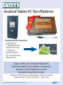
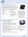
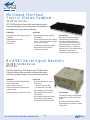
SOLUTIONS
FOR THE
WIRELESS WORLD
SOLUTIONS
POUR UN
MONDE SANS-FILS
Your account representative is:
2012
TABL E O F C O N T E N T S
Telecommunications
Guisys. . . . . . . . . . . . . . . . . . . . . . . . . . . . . . . . . . . . . . . . . . . . . . . . . . . . . . . . . . . . . 2-3
General Purpose Test and Measurement Instruments
Rohde & Schwarz . . . . . . . . . . . . . . . . . . . . . . . . . . . . . . . . . . . . . . . . . . . . . . . . . . . . 4-7
Rohde & Schwarz HAMEG . . . . . . . . . . . . . . . . . . . . . . . . . . . . . . . . . . . . . . . . . . . . 8-11
RF Site Measurement Products
Bird® Technologies Group – Bird Electronics Brand Products . . . . . . . . . . . . . . . . 12-14
dBm . . . . . . . . . . . . . . . . . . . . . . . . . . . . . . . . . . . . . . . . . . . . . . . . . . . . . . . . . . . . . . . 15
General Dynamics. . . . . . . . . . . . . . . . . . . . . . . . . . . . . . . . . . . . . . . . . . . . . . . . . . 16-17
Bird® Technologies Group – TX RX Systems Brand Products . . . . . . . . . . . . . . . . 19-27
RF Site Management Products
Trilogy – RF Cables (PCS, Cellular, Paging Broadcast and Microwave) . . . . . . . . . 28-31
Citel – RF Surge Protection . . . . . . . . . . . . . . . . . . . . . . . . . . . . . . . . . . . . . . . . . . 32-33
Android Tablet-PC Test Platform:
Existing GUISYS Innovation...
• Android v2.2
• 7” 800x480 WVGA
• Touchscreen GUI
..meets
• 3 USB ports
• Ethernet & Wi-Fi
• SD card expansion
• Web browser
State-of-the-Art Android Tablet-PC
based portable Test-system provides a
peerless User Experience with
exceptional performance.
Supports Android app’s: Web Browser, Maps, Streamed
Video & Audio, Contacts & Notes, ...and more!
See our web site for a full catalog: www.navair.com
2
NAVAIR
TECHNOLOGIES
Guisys GB 310 RITS
Intelligent Timing Test Set
GUISYS GB101: DS1 Test Set
Features
Features
eatures
•
•
•
•
•
•
•
•
•
•
•
•
•
•
•
•
•
•
Test and qualify your DS1 Timing & 64K Composite clocks
Verify both Tip & Ring pair
Measure Frequency, Voltages, Phase 360 deg. & uSec
Simple Pass/Fail display
Auto Fault Detection (Tip/Ring Open, No BPVs)
Auto 10-channel test and/or Single Channel
Local or Remote Interface Control
Fully-Integrated with DS1/DS0 or DS310 Test BRIC
Palm PDA or PC/Laptop Graphical User Interface
Comprehensive DS1 Test BRICK (3”x9”x1” <2lbs)
Single or Dual-Independent DS1 Test sets in 1 Package
Monitor both CO and Station or Drop DS0 to Butt-set
Complete Generic & 16-bit HDSL Loopback Codes
Smart or Intelligent Line Repeater Codes
Add DS3, PRI-ISDN, DS0-Data & DDS circuit testing
Add DS0-Voice, Signaling, 2-wire Signaling-TIMS
Test and Log Results using Circuit-ID’s
Uses Wired or BlueTooth Communication
GUISYS GB104: Signaling Test Set with
Wideband TIMS
GUISYS Pri-ISDN Test Set
FFeatures
t
FFeatures
t
•
•
•
•
•
•
•
•
•
•
•
•
•
•
•
Palm PDA or PC/Laptop Graphical User Interface (GUI)
Station (PBX) and CO Modes
Loop-Start, Ground-Start, DID, Immediate and WINK Signaling
Generate -48vDC Battery, RINGING and Dial-tone
Generate Tones and Measure Frequency, Level and Noise
2-wire 600, 900 and 1200 ohm Termination
Monitor Line Voltages and Current
Fully-Integrated with DS1/DS0, DS310 or PRI-ISDN Test BRICK
Run Three to Five Independent Circuit Tests with One BRICK!
Optional 100/135ohm Wide-band module measures to 2MHz
Programmed tones and Auto-Sweep from 20Khz to 2MHz simplify
insertion loss measurements for xDSL line qualification
See our web site for a full catalog: www.navair.com
•
•
•
•
•
•
3
PBX (TE) or CO (NT) Modes: Emulate the CPE or the Network
Up to 23 Simultaneous Calls on any B-Channel
Place and Receive Voice, Data or Audio Calls
Quick-TAP Q.931 Protocol Decodes into easy-to-read ASCII text
quickly identifies the cause of Call failures.
BERT the selected B-Channel (2047, 511, all-1’s, etc.)
Use Telset/Butt-set to Listen & Talk on any B-Channel
Fully-Integrated with DS1/DS0 or DS310 Test BRICK
Up to SIX Independent Test sets in One small test set!
Test and Log Results using Circuit-ID’s
Uses Wired or Wireless Communication
NAVAIR
TECHNOLOGIES
R&S®FSH4/8 Handheld Spectrum Analyzer
Key Features
• Frequency range from 9 kHz to 3.6 GHz or 8 GHz
• High sensitivity (<–141 dBm (1 Hz), with preamplifier
<–161 dBm (1 Hz))
• Low measurement uncertainty (<1 dB)
• Measurement functions for all important measurement
tasks related to the startup and maintenance of transmitter systems
• Internal tracking generator and VSWR bridge with built-in
DC voltage supply (bias)
• Two-port network analyzer
• Easy-to-replace Li-ion battery for up to 4.5 h of operation
• Rugged, splash-proof housing for rough work in the field
• Easy handling due to low weight (3 kg with battery) and
easy-to-reach function keys
• Saving of measurement results on SD card
• LAN and USB interface for remote control and transfer of
measurement data
• R&S®FSH4View software for simple documentation of
measurement results
R&S® FSH18 Spectrum Analyzer
Spectrum analysis anywhere, anytime –
on earth and in space
The R&S®FSH is the ideal spectrum analyzer for costeffective signal investigations in the field. It provides
a large number of measurement functions and so can
handle anything from the installation or maintenance of
a mobile radio base station up to on-site fault location in
RF cables to development and service — an extensive
range of applications.
Key Features
• Frequency range up to 18 GHz
• Easy operation, low weight and rugged design for field
use
• Four hours operating time on battery power
• Storage of up to 256 traces and setups
• Easy data transfer to PC
• High measurement accuracy
Keep an eye on it.
The R&S®FSL Spectrum Analyzer:
to see it is to want it.
The R&S®FSL is an extremely lightweight and compact spectrum analyzer that is
ideal for a large number of applications in development, service and production.
Despite its compact size, it offers a wealth of functions more typical of the highend range, thus ensuring an excellent price/performance ratio. The R&S®FSL
is the only instrument in its class that features a tracking generator up to
18 GHz and can analyze signals with a bandwidth of 28 MHz. In addition, the
R&S®FSL18, which operates at frequencies up to 18 GHz, supports applications
in the microwave range.
• 9 Khz to 3, 6 or 18GHz, with or without tracking generator
• Best performance in its class: DANL –142 dBm, IP3 typ. +10 dBm,
phase noise typ. –103 dBc
• Comprehensive measurement routines: TOI, OBW, Time Domain Power,
CCDF, channel/adjacent channel power
• LAN interface and USB host adapter
• Unique slide-in upgrade design: all hardware options are user-installable
without opening the housing
• FSL-K93 (option) WiMAX Application Firmware for spectrum and
modulation measurements on stationary and mobile WiMAX signals.
See our web site for a full catalog: www.navair.com
Note: there is one vital accessory for your R&S®FSL that we don’t carry. You’ll have to visit the
hardware store for that.
4
NAVAIR
TECHNOLOGIES
R&S®ZVH Cable and Antenna Analyzer
R&S®NRP2 Power Meter
Key Features
• Frequency range from 100 kHz to 3.6 GHz or 8 GHz
• 100 dB (typ.) dynamic range for filter and antenna isolation measurements
• Built-in DC voltage supply (bias) for active components such as amplifiers
• Power meter option
• Saving of measurement results on SD memory card or USB memory stick
• Easy operation with user-configurable test sequences (wizard)
• Easy-to-replace Li-ion battery for up to 4.5 h of operation
• Rugged, splash-proof housing for rough work in the field
• Easy handling due to low weight (3 kg with battery) and easy-to-reach
function keys
Key Features
• Power measurements with a base unit or with cost-efficient USB
power sensors alone
• Average, peak and peak-to-average power measurements from DC to
67 GHz
• Versatile USB power sensors with superior performance
• Accurate measurements for GSM/EDGE, 3G, WLAN, WiMAX™, LTE
and beyond
• Complex signals with digital modulation are handled as easily as are
CW signals, carriers with analog modulation and pulsed RF
• Solutions for radar and EMC applications
• Ultra-fast statistical analysis
• Flexible use with signal generators, signal analyzers and network
analyzers from Rohde & Schwarz
R&S®CTH100A/R&S®CTH200A Portable Radio Test Set
Key Features
• Frequency measurement
• Power measurement
• Over-the-air measurement (R&S®CTH200A)
• Distance-to-fault measurement (R&S®CTH200A)
• Voice reporting (R&S®CTH200A)
R&S®NRP-Z Sensors
R&S®FSC Spectrum Analyzer
Brief Description
No matter whether you work in the lab or in production – the Microwave
Power Meter R&S®NRP is always the right choice. The versatility of
the novel Power Meter Series R&S®NRP is due to the newly developed
sensors. These sensors are intelligent standalone instruments that
communicate with the base unit or a PC via a digital interface. The SMART
SENSOR TECHNOLOGY™ now implemented for the first time, sets new
standards in terms of universality and accuracy.
Key Features
• Frequency range 9 kHz to 3 GHz or 6 GHz
• Resolution bandwidths 10 Hz to 3 MHz
• High sensitivity (< –141 dBm (1 Hz), with optional preamplifier
< –161 dBm (1 Hz ))
• High third order intercept (> 10 dBm, typ. 15 dBm)
• Low measurement uncertainty (< 1 dB)
• Internal tracking generator (model .13/.16)
• Compact dimensions
• Low power consumption (12 W)
See our web site for a full catalog: www.navair.com
Key Features
• Dynamic range: up to 90 dB (sensor dependent)
• Level range: -67 dBm to +45 dBm (sensor dependent)
• Frequency range: DC to 67 GHz (sensor dependent)
• Measurement speed: 1500 measurements per second in the buffered mode
• Linearity uncertainty: 0.0007 dB
• Precise average power measurements irrespective of modulation type and
bandwidth
• Flexible measurements on up to 128 time slots per power sensor (26 time
slots with base unit)
• Direct USB connection from sensor to a PC
• S parameter correction of components between sensor and test object
• 2 years calibration cycle for base unit as well as for the sensors
5
NAVAIR
TECHNOLOGIES
Analog & Vector Signal Generators
ZVL Vector Network Analyzer
The cost-efficient compact class in network analysis
•
•
•
•
•
•
• Digital communications standards
• Accurate power measurement (USB connector for R&S® NRP-Z power
sensor series)
• Compact size and low weight (<7 kg)
• 12 V DC operation and internal battery
• Connection for external monitor
Frequency ranges from 9 kHz to 3 GHz/6 GHz/13.6 GHz
Wide dynamic range: >115 dB, typ. 123 dB
Bidirectional test set: display of all four S-parameters
75 Ω version from 9 kHz to 3 GHz for TV/CATV
Complete spectrum analyzer as an option
Compact size and low weight (<7 kg)
The New Standard of Excellence
in Analog Signal Generation
R&S®SMA100A
Key Features
Setting Standards in Mid-range
Analog Signal Generation
R&S®SMB100A
Key Features
• Frequency range from 9 kHz to 3 GHz or 6 GHz
with or without an electronic attenuator
• CW signal and all common types of analog
modulations (AM, FM, φM, PM)
The R&S®SMA100A combines superior signal
•
Very low phase noise
quality with a very high setting speed, making it
•
High power output as standard
the ideal generator for any task in development,
• Optional removable mass memory card
production, service or maintenance.
The R&S®SMB100A sets new standards in its
class due to its outstanding characteristics. The
instrument combines excellent signal quality with
very high output power, which makes it ideal for
any task.
• Wide frequency range from 9 kHz to
1.1/2.2/3.2/6 GHz or from 100 kHz to
12.75/20/40 GHz
• Excellent signal characteristics with low
SSB phase noise of typ. –128 dBc
(at 1 GHz, 20 kHz offset)
• High output power of typ. up to +27 dBm
• All important analog modulations with AM,
FM/φM and pulse modulation supported
• Compact size with only two height units,
3/4 19” width and low weight
Best Price/Performance Ratio and Key Features
• Frequency range from 9 kHz to 1.1 GHz
Smallest Size in its Class
R&S®SMC100A
The R&S®SMC100A is the newest analog
signal generator that Rohde & Schwarz has
to offer. It has a very small size and is priced
very attractively to reduce overall total cost
of ownership.
See our web site for a full catalog: www.navair.com
6
or 3.3 GHz
• Outstanding signal quality
• All analog modulation types and high output
power as standard
• Electronic attenuator
• Low phase noise and fast switching time
NAVAIR
TECHNOLOGIES
Analog & Vector Signal Generators
Generating Signals for Today
and Tomorrow
R&S®SMBV100A
The R&S®SMBV100A is a state-of-the art vector
signal generator that has been designed with a
future-proof hardware concept.
Compact, cost-effective
measuring receiver
R&S®ESL EMI Test Receiver
The R&S®ESL EMI test receiver combines
two instruments in one, measuring EMC
disturbances in accordance with the latest
standards and also serving as a full-featured
spectrum analyzer for diverse lab applications.
The R&S®ESL is the ideal instrument for small
budgets.
Key Features
• Frequency range from 9 kHz to 3.2 GHz
or 6 GHz
• Excellent characteristics and high output power
as standard
• Wide RF signal bandwidth of up to 120 MHz with
internal signal generation
• Maximum supported external RF bandwidth is
500 MHz
• Supports all of the important digital standards
available now such as WiMAX, 3GPP and LTE,
as well as any future digital standards still in
development
Key Features
• Frequency range from 9 kHz to 3 GHz or 9 kHz
to 6 GHz covering almost all commercial EMC
standards
• First-ever combination of an EMI test receiver
and spectrum analyzer in the entry-level class
• All major functions of an advanced EMI test
receiver, including fully automated test sequences
• Weighting detectors: max./min. peak, average,
RMS, quasi-peak as well as average with meter
time constant and rms-average in accordance
with the latest version of CISPR 16-1-1
• Compact, lightweight instrument, can be batterypowered for mobile applications
R&S®HE300
Active Directional Antenna
20 MHz (optional 9 kHz) to 7.5 GHz
Key Features
The practical and very wideband R&S®HE300
active directional antenna locates transmitters
and interference sources when combined with
portable receivers (e.g. the R&S®PR100).
• Very wideband performance in a practical size
Three exchangeable antenna modules that are
supplied with the antenna cover the 20 MHz to
7.5 GHz frequency range. An additional module
(R&S®HE300HF for 9 kHz to 20 MHz) is available
as an option.
• Unambiguous radiation pattern
• Direction is found by orienting antenna toward
maximum field strength
• Low weight, due to optimized selection of
materials, ensures fatigue-proof handling
• Horizontal and vertical polarization
• Wide dynamic range
• Passive antenna if amplifier is switched off
The modules can be plugged into the handle
with the correct orientation for vertical or
horizontal polarization and then mechanically
locked in place.
A built-in, low-noise wideband amplifier can be
activated to enhance system sensitivity (active
mode).
In passive mode, the amplifier is bypassed so
that the R&S®HE300 can also be used in the
vicinity of strong signal sources.
See our web site for a full catalog: www.navair.com
7
NAVAIR
TECHNOLOGIES
Oscilloscopes
250MHz 4 Channel Digital Oscilloscope
HMO2524
350MHz 2[4] Channel Digital Oscilloscope
HMO3522 [HMO3524]
❑ 4 GSa/s Real Time, 50 GSa/s Random Sampling, Low Noise Flash A/D Converter
(Reference Class)
❑ 4 MPts Memory, Memory
oom up to 100,000:1
❑ MSO (Mixed Signal Opt. HO3508 [HO3516]) with 8 [16] Logic Channels
❑ Serial Bus Trigger and Hardware accelerated Decode incl. List View, I2C, SPI, UART/
RS-232, CAN, LIN (optional)
❑ Automatic Search for User defined Events
❑ Pass/Fail Test based on Masks
❑ Vertical Sensitivity 1 mV/div., Offset Control ±0.2...±20 V
❑ 12 div. x-Axis Display Range, 20 div. y-Axis Display Range (VirtualScreen)
❑ Trigger Modes: Slope, Video, Pulsewidth, Logic, Delayed, Event
❑ 6 Digit Counter, Automeasurement: max. 6 Parameters incl. Statistic, Formula Editor,
Ratiocursor, FFT: 64 kPts
❑ Crisp 16.5 cm (6.5”) TFT VGA Display, DVI Output
❑ Lowest Noise Fan
❑ 3 x USB for Mass Storage, Printer and Remote Control optional IEEE-488 (GPIB) or
Ethernet/USB
❑ 2.5 GSa/s Real Time, 25 GSa/s Random Sampling, Low Noise Flash A/D Converter
(Reference Class)
❑ 4 MPts Memory, Memory
oom up to 100,000:1
❑ MSO (Mixed Signal Opt. HO3508 [HO3516]) with 8 [16] Logic Channels
❑ Serial Bus Trigger and Hardware accelerated Decode incl. List View, I2C, SPI, UART/
RS-232, CAN, LIN (optional)
❑ Automatic Search for User defined Events
❑ Pass/Fail Test based on Masks
❑ Vertical Sensitivity 1 mV/div., Offset Control ±0.2...±20 V
❑ 12 div. x-Axis Display Range, 20 div. y-Axis Display Range (VirtualScreen)
❑ Trigger Modes: Slope, Video, Pulsewidth, Logic, Delayed, Event
❑ 6 Digit Counter, Automeasurement: max. 6 Parameters incl. Statistic, Formula Editor,
Ratiocursor, FFT: 64 kPts
❑ Crisp 16.5 cm (6.5”) TFT VGA Display, DVI Output
❑ Lowest Noise Fan
❑ 3 x USB for Mass Storage, Printer and Remote Control optional IEEE-488 (GPIB) or
Ethernet/USB
70MHz/100MHz 2[4] Channel
Digital Oscilloscope
HMO722 [HMO724]/HMO1022 [HMO1024]
150MHz/200MHz 2[4] Channel
Digital Oscilloscope
HMO1522 [HMO1524]/HMO2022 [HMO2024]
NEW
❑
❑
❑
❑
❑
❑
❑
❑
❑
❑
❑
❑
❑
NEW
❑
❑
❑
❑
2 GSa/s Real Time, Low Noise Flash A/D Converter (Reference Class)
2 MPts Memory, Memory
oomoom up to 50,000:1
MSO (Mixed Signal Opt. HO3508) with 8 Logic Channels
Serial Bus Trigger and Hardware accelerated Decode incl. List View, I2C, SPI, UART/
RS-232, CAN, LIN (optional)
Automatic Search for User defined Events
Pass/Fail Test based on Masks
Vertical Sensitivity 1 mV/div., Offset Control ±0.2...±20 V
12 div. x-Axis Display Range, 20 div. y-Axis Display Range (VirtualScreen)
Trigger Modes: Slope, Video, Pulsewidth, Logic, Delayed, Event
Component Tester, 6 Digit Counter, Automeasurement: max. 6 Parameters incl.
Statistic, Formula Editor, Ratiocursor, FFT: 64 kPts
Crisp 16.5 cm (6.5”) TFT VGA Display, DVI Output
Lowest Noise Fan
3 x USB for Mass Storage, Printer and Remote Control optional IEEE-488 (GPIB) or
Ethernet/USB
See our web site for a full catalog: www.navair.com
❑
❑
❑
❑
❑
❑
❑
❑
❑
8
2 GSa/s Real Time, Low Noise Flash A/D Converter (Reference Class)
2 MPts Memory, Memory
oomoom up to 50,000:1
MSO (Mixed Signal Opt. HO3508) with 8 Logic Channels
Serial Bus Trigger and Hardware accelerated Decode incl. List View, I2C, SPI, UART/
RS-232, CAN, LIN (optional)
Automatic Search for User defined Events
Pass/Fail Test based on Masks
Vertical Sensitivity 1 mV/div.
12 div. x-Axis Display Range, 20 div. y-Axis Display Range (VirtualScreen)
Trigger Modes: Slope, Video, Pulsewidth, Logic, Delayed, Event
Component Tester, 6 Digit Counter, Automeasurement: max. 6 Parameters incl.
Statistic, Formula Editor, Ratiocursor, FFT: 64 kPts
Crisp 16.5 cm (6.5”) TFT VGA Display, DVI Output
Lowest Noise Fan
3 x USB for Mass Storage, Printer and Remote Control optional IEEE-488 (GPIB) or
Ethernet/USB
NAVAIR
TECHNOLOGIES
HMO – Innovations in Oscilloscopes
VirtualScreen — a HAMEG only and industry first
in oscilloscopes.This feature make the handling of
many signals easy. The extension to 20 Division is
access able with one button and the universal knob.
Built in signal source for square wave, serial pattern
(I2C, SPI, UART) or 4 bit wide parallel (random
or counter pattern ) — again a HAMEG only and
industry first.
HMO – sensitive, low noise and fast
All HMO scopes have hardware sensitivity of
1mV/div and have the lowest noise — required
for accurate measurements at small signals.
See our web site for a full catalog: www.navair.com
The new HMO series have an update rate of up
to 2000 waveforms per second. For example this
enables the display of modulated signals.
9
NAVAIR
TECHNOLOGIES
Spectrum Analysis
1GHz [3GHz] Spectrum Analyzer
HMS1000 [HMS3000]
❑ Frequency Range 100 kHz…1 GHz [3 GHz]
❑ Tracking Generator HMS1010 [HMS3010] -20…0 dBm
❑ Amplitude Measurement Range -114…+20 dBm DANL -135 dBm with Preamp.
Option HO3011
❑ Sweep Time 20 ms…1000s
❑ Resolution Bandwidth 100 Hz…1 MHz in 1–3 Steps, 200 kHz (-3 dB); additional
200 Hz, 9 kHz, 120 kHz, 1 MHz (-6 dB)
❑ Spectral Purity <-100 dBc/Hz (@100 kHz)
❑ Video Bandwidth 10 Hz…1 MHz in 1–3 Steps
❑ Integrated AM and FM Demodulators (Phone and int. Speaker)
❑ Detectors: Auto-, Min-, Max-Peak, Sample, RMS, Quasi-Peak
❑ 8 Markers with Delta Marker, miscellaneous Peak Functions
❑ Crisp 16.5 cm (6.5”) TFT VGA Display, DVI Output
❑ 3 x USB for Mass-Storage, Printer and Remote Control
1GHz Spectrum Analyzer
HMS1000E
NEW
❑ Frequency Range 100 kHz…1 GHz
❑ Amplitude Measurement Range -104…+20 dBm
❑ Sweep Time 20 ms…1000s
❑ Resolution Bandwidth 10 kHz…1 MHz in 1–3 Steps, 200 kHz (-3 dB)
❑ Spectral Purity <-100 dBc/Hz (@100 kHz)
❑ Video Bandwidth 1 kHz…1 MHz in 1–3 Steps
❑ Integrated AM and FM Demodulator (Phone and int. Speaker)
❑ Detectors: Auto-, Min-, Max-Peak, Sample, RMS
❑ 8 Marker with Delta Marker, miscellaneous Peak Functions
❑ Crisp 16.5 cm (6.5”) TFT VGA Display
❑ 3 x USB for Mass-Storage, Printer and Remote Control,
EMC-PCS1
EMC Precompliance Set 1 (1 GHz)
The EMI pre compliance Set from HAMEG consist of all necessary instruments and software to measure typical EMI
problems. It includes the modern spectrum analyzer HMS1000, the Line Impedance Stabilization Network HM6050-2,
the HZ530 probe set and the HM Explorer software for Windows.
HMS1000
❑ 1 GHz Spectrum Analyzer
❑ Frequency Range 100kHz…1GHz
❑ Sweep Time 20ms…1000s
❑ Resolution Bandwidth 1kHz…1MHz in 1–3 Steps,
200kHz (-3dB), additional 9kHz, 120kHz, 1MHz (-6dB)
❑ Video Bandwidth 10Hz…1MHz in 1–3 Steps
HM6050-2
❑ Line Impedance Simulation Network
❑ Measurement of Line-conducted Interference
within the Range from 9kHz…30MHz (CISPR 16)
Switchable Transient Limiter
❑ Artificial Hand Connector
See our web site for a full catalog: www.navair.com
10
HZ530
❑ The HZ530 Probe Set consists of three active
broadband probes for EMI diagnosis.
❑ H-field probe
❑ High-impedance probe
❑ E-field probe
HM Eplorer
Spectrum Analyzer software HM Explorer to make the
EMI pre complicance measurements.( support Standard
Interface HO720 RS232/USB and Windows®)
NAVAIR
TECHNOLOGIES
Power Supplies
Programmable 3[4] Channel
High-Performance Power Supply
HMP4030 [HMP4040]
❑ 3 x 0…32 V/0…10 A 384 W max.
[4 x 0…32 V/0…10 A 384 W max.]
❑ 384 W Output Power realized by intelligent Power Management
❑ Low Residual Ripple: <150 µVrms due to linear Post Regulators
❑ High Setting- and Read-Back Resolution of 1 mV up to 0.2 mA
❑ Keypad for direct Parameter Entry
❑ Galvanically isolated, earth-free and short circuit protected Output Channels
❑ Advanced Parallel- and Serial Operation via V/I Tracking
❑ EasyArb Function for free definable V/I Characteristics
❑ FuseLink: Individual Channel Combination of Electronic Fuses
❑ Free adjustable Overvoltage Protection (OVP) for all Outputs
❑ All Parameters clearly displayed via LCD/Illuminated Buttons
❑ Rear Connectors for all Channels including Sense
❑ USB/RS-232 Interface, optional Ethernet/USB or IEEE-488 (GPIB)
Programmable 2[3] Channel
High-Performance Power Supply
HMP2020 [HMP2030]
❑ 1 x 0…32 V/0…10 A
[3 x 0…32 V/0…5 A
1 x 0…32 V/0…5 A
188 W max.]
188 W max.
❑ 188 W Output Power realized by intelligent Power Management
❑ Low Residual Ripple: <150 µVrms due to linear Post Regulators
❑ High Setting- and Read-Back Resolution of 1 mV up to 0.1 mA
❑ Galvanically isolated, earth-free and short circuit protected Output Channels
❑ Advanced Parallel- and Serial Operation via V/I Tracking
❑ EasyArb Function for free definable V/I Characteristics
❑ FuseLink: Individual Channel Combination of Electronic Fuses
❑ Free adjustable Overvoltage Protection (OVP) for all Outputs
❑ All Parameters clearly displayed via LCD/Illuminated Buttons
❑ Rear Connectors for all Channels including Sense
❑ USB/RS-232 Interface, optional Ethernet/USB or IEEE-488 (GPIB)
Triple Power Supply
HM7042-5
❑ 2 x 0…32 V/0…2 A 1 x 0…5.5 V/0…5 A
❑ High-Performance and inexpensive Laboratory Power Supply
❑ Floating, overload and short-circuit proof Outputs
❑ Separate Voltage and Current Displays for each Output 4 Digits at Channel 1+3; 3 Digits at Channel 2
❑ Display Resolution: 10 mV/1 mA at Channel 1+3; 10 mV/10 mA at Channel 2
❑ Protection of sensitive Loads by Current Limit or Electronic Fuse
❑ Pushbutton for activating/deactivating all Outputs
❑ Low Residual Ripple, high Output Power, very good Regulation
❑ Parallel (up to 9 A) and Series (up to 69.5 V) Operation
❑ Temperature-controlled Fan
See our web site for a full catalog: www.navair.com
11
NAVAIR
TECHNOLOGIES
Programmable Measuring
25MHz [50MHz] Arbitrary
Function Generator
HMF2525 [HMF2550]
6½ – Digit Precision Multimeter
HM8112-3 [HM8112-3S]
❑ Frequency Range 10 µHz…25 MHz [50 MHz]
❑ 6½-Digit Display (1,200,000 Counts)
❑ Output Voltage 5 mVpp…10 Vpp (into 50 Ω) DC Offset ±5 mV…5 V
❑ Resolution: 100 nV, 100 pA, 100 µΩ, 0.01 °C/F
❑ Arbitrary Waveform Generator: 250 MSa/s, 14 Bit, 256 kPts
❑ DC Basic Accuracy 0.003 %
❑ Sine, Square, Pulse, Triangle, Ramp, Arbitrary Waveforms incl. Standard Curves
(white Noise, Cardiac etc.)
❑ 2-Wire/4-Wire Measurements
❑ Total harmonic Distortion 0.04 % (f <100 kHz)
❑ Up to 100 Measurements per Second transmitted to a PC
❑ Burst, Sweep, Gating, external Trigger
❑ True RMS Measurement, AC and DC+AC
❑ Rise Time <8 ns, in Pulse Mode 8…500 ns Variable-Edge-Time
❑ Mathematic Functions: Limit Testing, Minimum/Maximum, Average and Offset
❑ Pulse Mode: Frequency Range 100 µHz…12.5 MHz [25 MHz], Pulse Width
15 ns…999 s, Resolution 5 ns
❑ Temperature Measurements with Platinum (PT100/PT1000) and Ni (K and J types) Sensors
❑ Measurement Intervals adjustable from 0.1…60 s
❑ Internal Data Logger for up to 32,000 Measurement Results
❑ Modulation Modes AM, FM, PM, PWM, FSK (int. and ext.)
❑ Offset Correction
❑ 10 MHz Timebase: ±1 ppm TCXO, rear I/O BNC Connector
❑ Galvanically isolated USB/RS-232 Interface, optional IEEE-488 (GPIB)
❑ Front USB Connector: Save and Recall of Waveforms and Settings
❑ [HM8112-3S]: HM8112-3 incl. Scanner
❑ 8.9 cm (3.5”) TFT: crisp Representation of the Waveform and all Parameters
❑ USB/RS-232 Dual-Interface, optional Ethernet/USB or IEEE-488 (GPIB)
3GHz Programmable Counter
HM8123
200kHz LCR-Bridge
HM8118
❑ Basic Accuracy 0.05 %
❑ Measurement Range 0 Hz…3 GHz
❑ Measurement Functions L, C, R, |Z|, X, |Y|, G, B, D, Q, , , M, N
❑ 2 Measurement Inputs DC…200 MHz, 1 Measurement Input 100 MHz…3 GHz
❑ Test Frequencies 20 Hz…200 kHz
❑ Input Impedance A/B: 1 MΩ/50 Ω (switchable), Sensitivity 25 mVrms
❑ Up to 12 Measurements per Second
❑ Input Impedance C: 50 Ω, Sensitivity 30 mVrms
❑ Parallel and Series Mode
❑ 400 MHz Time Base with 0.5 ppm Stability
❑ Binning Interface HO118 (optional) for automatic Sorting of Components
❑ 10-Digit Resolution at 10 s Gate Time
❑ Internal programmable Voltage and Current Bias
❑ 9 Measurement Functions, external Gate and Arming
❑ Transformer Parameter Measurement
❑ Input for external Time Base (10 MHz)
❑ External Capacitor Bias up to 40 V
❑ Kelvin Cable and 4-Wire SMD Test Adapter included in Delivery
❑ Standard: TCXO (Temperature Stability: ±0.5 x 10⁻⁶) Optional: OCXO (Temperature
Stability: ±1 x 10⁻⁸)
❑ Galvanically isolated USB/RS-232 Interface, optional IEEE-488 (GPIB)
❑ Intuitive One-Pushbutton Operation. Each Function directly Addressable
❑ Galvanically isolated USB/RS-232 Interface, optional IEEE-488 (GPIB)
See our web site for a full catalog: www.navair.com
12
NAVAIR
TECHNOLOGIES
SignalHawktm
SIGNALHAWKTM VNA | Spectrum Analyzer with Power Meter Option
MODEL SH-362S: Spectrum Analyzer & 2-Port VNA
MODEL SH-361S: Spectrum Analyzer & 1-Port VNA
MODEL SH-362: 2-Port VNA (1.6MHz-3.6GHz)
MODEL SH-36S: Spectrum Analyzer (100kHz to 3.6GHz)
Bird Technologies SignalHawkTM Analyzes radio frequency spectrum.
Measures intended and interfering signals. Allows setup of parameters
such as frequency, amplitude, and markers. Graphically displays signal
amplitude vs. frequency and saves traces.
KEY FEATURES
• Fast, Accurate, and Sensitive: -42 dB Directivity and-135 dBm Noise Floor
• Large High-Resolution Display: Full Color, Indoor/Outdoor Viewable
• Easy-to-Use: Intuitive Menus, One-Button Setup, and On-Board Help
• Long Battery Life: 5.5 Hours per Charge, Field Replaceable Battery
• Rugged: Drop Tested per Military and European Standards
• USB Connectivity: USB Drive Stores 90,000 Traces
• Spectrogram
• GPS
• Power measurement interface
• Internal Bias – Tee
Model SH-36S SignalHawkTM
ALSO AVAILABLE
Bird®Rack-Mount SignalHawkTM Spectrum Analyzer
Model SH-36S-RM: 100kHz to 3.6 GHz
Remotely analyzes the radio frequency spectrum. From your office: measures
intended and interfering signals, allows setup of parameters such as frequency and
amplitude markers. Also, remotely displays signal amplitude vs. frequency and saves
traces to your PC.
Bird®PC SignalHawk Spectrum Analyzer
Model SH-36S-PC: 100kHz to 3.6 GHz
Analyzes the radio frequency spectrum. Measures intended and interfering signals, allows
setup of parameters such as frequency and amplitude markers. Also, displays signal
amplitude vs. frequency and saves traces on your PC.
WORLDWIDE APPLICATIONS
Cellular, PCS, DCS, 2G, 3G, 4G, CDMA, cdmaOne, CDMA 2000, 1x, 1x EV-DO, GSM, GPRS, EDGE, UMTS, HSDPA,W-CDMA, TDMA,
AMPS 802.11, Bluetooth, Broadcast, Emergency, Fire, GPS, HDTV, IBOC, In-Building, Lab, Microwave, NPSPAC, Paging, Police, Private,
Project 25, Public Safety, Tactical Military, Telematics, Tetra, Trunking, Utilities,WiMAX,WLAN and WLL.
See our web site for a full catalog: www.navair.com
13
NAVAIR
TECHNOLOGIES
Bird® Model 5000-XT
Hand-Held Digital Power Meter
The hand-held digital power meter has been completely redesigned with the new Bird® 5000-XT. Ideally suited
for field techs and engineers who need to make power measurements anywhere they go, the 5000-XT’s new
user interface has an intuitive, menu-driven design, making it the easiest to use on the market. It’s operable
even with one hand and compatible with all our field and legacy sensors.
Bird® AT Series
AT-500 & AT800
Antena Testers
The Bird AT-Series Antenna Testers provide a cost-effective, fast, graphical
way of determining the quality of mobile and base station antennas.
• Rugged, easy-to-use, hand-held design with extended battery life makes it ideal
for use in the field.
• Tests the system in VSWR, Return Loss, Match Efficiency, or Reflection
Coefficient (Rho)
• Single frequency readings and frequency sweeps allow for everything from
pinpointests to system optimization and tuning.
• Can save up to 12 traces for comparison and tracking over time
• RS232 Interface allows communication with a PC for saving traces using
the optional software.
Frequency Characteristics:
Frequency Range
AT 500
2 to 520 MHz
Minimize
Downtime
®
Bird Antenna
Keep Your Critical
Antenna Sites
Up & Running
BIRD® ANTENNA & CABLE MONITOR
Accurately detects antenna system degradation and failures
Cable Monitor
•
•
•
•
•
•
Compatible with analog or digital cellular and two-way radio systems
Worldwide applications include Tetra, Cellular, PCS and many others
Monitors VSWR and power levels and provides alarm outputs
Sensitive to antenna faults that internal transmitter VSWR monitors may not detect
Local or remote operation via PC software
Ideal for multi-carrier applications
See our web site for a full catalog: www.navair.com
14
Antenna &
Cable Monitor
PC Software Tool
7005A970
(Optional Accessory)
NAVAIR
TECHNOLOGIES
Bird®Wideband Power Sensor
5012A, 5016, 5017, 5018, 5019
Bird’s® Wideband Power Sensor (WPS) never requires field calibration, only
requires calibration once per year and is traceable to National Institute of Standards
and Technology (NIST). The WPS measures True Average Power, Peak Power, and
Duty Cycle directly with exceptional accuracy and uses these precise measurements
to calculate a wide range of other important factors, such as VSWR, Return Loss,
Reflection Coefficient, Crest Factor, Average Burst Power, and CCDF.
PROBLEMS
Downtime is necessary
Have analog, digital, and multi-carrier signals
to measure
Tight budgets
Varying field tech skill levels
Need greater confidence in measurement
SOLUTIONS
Monitor and perform maintenance for
monitoring while DUT is in-service
Measure forward and reflected power to
troubleshoot system failures
Modulation independent measurements
USB connectivity, no meter required
Sensor plugs and plays with 5000-XT meter
No field calibration required
NIST traceable calibration
APPLICATIONS
WPS measures: Analog Cellular, Digital
Cellular, 3G, 4G, Tetra, APCO/P25, Trunking,
CDMA, TDMA, WCDMA, GSM, Transportation,
Tactical Military, Radar, Avionics, Marine, LMR,
Analog Broadcast, Digital Broadcast, GSM,
GPRS, EDGE, UMTS, HSDPA, Bluetooth, Fire,
GPS, NPSPAC, Paging, Project 25, Public
Safety, Telematics, Utilities, WIMAX and WLAN.
Measurements performed: Peak power, true
average power and Duty Cycle.
Calculations Performed: VSWR, Return Loss,
Reflection Coefficient, Crest Factor, Average
Burst Power and CCDF.
Bird®Site Analyzer XT Series
SA-3600XT (25-3600 MHz)
SA-6000XT (25-6000 MHz)
• One unit covers the entire 25-6000 MHz range!
• Easy to operate and field ready for first-time, occasional and experienced users.
• Other applications include 3G, Broadcast, Government, Tactical Military,
Microwave, Paging, Public Safety, Trunking, WLAN and WLL, and TETRA.
• Color display is clearly visible in direct sunlight.
• With a single download you can view data as Distance to Fault or Measurement
Match-no need to store two traces.
• FDR (Frequency Domain Reflectometry) measurement method results in a
highly reliable assessment of the health of critical components in your system;
ultimately providing a “heads-up” before a failure occurs.
• Fault location or DTF mode indicates VSWR or Return Loss levels at each point
along the cable and antenna system length.
• Cable Loss function measures insertion loss of the cable system over a given
frequency range.
• USB communication ports for connection to PC, field sensors and storage devices.
See our web site for a full catalog: www.navair.com
15
APPLICATIONS
Suitable for use in Worldwide Cellular and
PCS/DCSsystems; supporting measurement
of CDMA, GSM, TDMA and AMPS modulation
schemes.
Other applications include 3G,
Broadcast,Government, Tactical Military,
Microwave, Paging,Public Safety, Trunking,
WLAN and WLL, and TETRA.
NAVAIR
TECHNOLOGIES
Carrier to Noise Generator CNG-70/140
RF Converter Series UDC-172-302-2
APPLICATIONS:
• Bit error rate/SINAD testing
• SATCOM modems
• Channel impairment tests
• Development, qualification, and verification testing
• Manufacturing test
APPLICATIONS:
• A laboratory workhorse
• Programmable LO for frequency converters
• Frequency hopping source
• RF device characterization
• Tracking generator source
FEATURES:
• C/N, C/No, Eb/No, and C/I modes
• 1 or 2 independent RF channels
• Continuous input power monitoring
• Un-interrupted signal path during calibration cycle
• IEEE-488.2 and RS-232 interface
• Easy to read VFD display
FEATURES:
• Low noise (-103 dBc/Hz 1 kHz offset @ 1GHz)
• Fast switching (<2msec typ.)
• Small and lightweight (10” x 10” x 3”)
• Non-volatile memory for storage/recall of instrument settings
• IEEE-488.2, LAN, and RS-232 interfaces standard
Satellite Link Emulator SLE9000 Series
Precision White Gaussian Noise Generator
OPTIONS:
• Fast switching speed (200 usec)
• File driven hopping/swept frequency mode
APPLICATIONS:
• Bit error rate (BER) and SINAD testing
• Component and subsystem linearity characterization
• Wireless link emulation
APPLICATIONS:
• Earth terminal testing
• Satellite payload testing
• Satellite system integration test beds
• Mobile transceiver testing
• UAV Testing
FEATURES:
• Calibrated noise density over entire operating frequency
• Noise power/bandwidth and noise density control
• Solid state noise attenuator with 0.0156 dB resolution
• IEEE-488.2 interface
Optional
• Multipath Fading, 6 paths
• Digitally generated AWGN
Multiple Orbit Models
Emulates earth-to-satellite-to-earth, earth-to-satellite links; Low Earth
Orbit; Medium Earth Orbit, Geostationary and Geosynchronous, satellite
to satellite links and satellite to UAV testing.
Test Data Generation
dBm’s standard SATGEN software data generation package or Analytical
Graphics STKTM package may be used to generate the necessary test
data. SLEControl, a windows based applet will automatically format
download the test files for execution in dynamic mode.
See our web site for a full catalog: www.navair.com
16
NAVAIR
TECHNOLOGIES
R8000B Communications System Analyzer
“General Dynamics is pleased to announce the second generation of its
revolutionary R8000 communications system analyzer. The R8000B delivers a
previously unimaginable result: a truly portable radio test set with more functions
than yesterday’s bench top analyzers. And it now offers industry-leading spectral
purity, surpassing that of comparably priced and even much more expensive radio
test sets.
The R8000’s 14 pound weight gives technicians power and flexibility never before
attainable – or currently attainable with any other instrument. This, combined
with the unit’s feature-packed spectrum analyzer and bright 8.4” color LCD,
makes it ideal for taking to sites for infrastructure maintenance and interference
measurement.
Firmware upgrades are available free via web download for the life of the unit,
and new capabilities are being constantly added — so your R8000B actually
becomes more powerful over time! Software and protocol options can also be
added directly from the front panel in less than 30 seconds; so it is clear that the
R8000B is the most flexible, robust future-proofed radio test set the industry has
ever seen. The R8000B will change the way you perform radio service forever.”
A Compact and Lightweight Solution
You no longer need to lug multiple pieces of heavy equipment to perform service at remote locations. The R8000 has everything you need in
one compact, 14 lb. package! Among the instruments included in the R8000 are:
• AM Modulation Meter
• Receive Signal Strength Meter
• Broadband and Narrowband Power Meters
• Audio Counter
• Audio Generator
• AC / DC Voltmeters
• DMR (MOTOTRBO™) test mode (optional)
• NXDN test mode (optional)
• TETRA Subscriber Test (optional)
• P25 test mode (optional)
• Spectrum Analyzer
• Signal Generator
• Sensitive Measurement Receiver
• Tracking Generator (optional)
• SINAD Meter
• Distortion Meter
• Modulation Scope
• Oscilloscope
• Frequency Error Meter
• Cable Fault Locator (optional)
• FM Deviation Meter
The R2600 Series: The industry proven test solution for APCO™ Project 25
SMARTNET/ SmartZone®, ASTRO®, SECURENET®, and conventional two way radio.
The R2600 family of Communications System
Analyzers performs tests normally associated with
these instruments:
• RF Signal Generator
• Sensitive Measurement Receiver
• Spectrum Analyzer
• Full Band Duplex Offset Generator
• Frequency Counter
• AC/DC Voltmeter
• 50 kHz Oscilloscope
• RF Wattmeter
• Signal Strength Meter
• Frequency Error Meter
• SINAD Meter
• Distortion Meter
• Sweep Generator
• Audio Generator
• Modulation Analyzer
• Signaling Simulator
• RF Scan/Counter
• High Performance Spectrum Analyzer with Markers
Optional in R2600 & R2625; standard in R2670:
APCO is a registered trademark of the Association of Public Safety Officials ASTRO,
SECURENET and SMARTNET/SAMARTZONE is a registered trademark of Motorola Inc.
• Cable Fault Locator
• Tracking Generator
See our web site for a full catalog: www.navair.com
17
• Programmable Test Set-Ups
NAVAIR
TECHNOLOGIES
R2660 iDEN™ Digital
Communications System Analyzers
R2600D – For Conventional Radio and Paging Service
FEATURES:
• RF Signal Generator
• Sensitive Measurement Receiver
• Spectrum Analyzer
• Duplex Offset Generator
• Frequency Counter
• AC/DC Voltmeter
• 50 kHz Oscilloscope
• RF Wattmeter
• Signal Strength Meter
FEATURES:
• Average power meter
• Frequency error meter
• SQE (Signal Quality Estimate)
• Tracking generator
• Cable fault locator
• High stability oscillator
• Enhanced spectrum analyzer with markers
• Test memory presets
• BER (Bit Error Rate)In addition to offering all the standard system features,
the R2660 also includes several high performance features for testing
more sophisticated systems. R2660 Standard System Capabilities
iDEN-Specific Test Capabilities
• Supports both 6:1 and 3:1 TDMA format
• Subscriber unit testing in dynamic call simulation mode including vocoder
for live voice testing
• Subscriber unit testing in test mode
• Base site transmitter testing under operating conditions
• Base site receiver BER testing General Diagnostic Features
R2670B Communications System Analyzer
Radio and Paging
g g Service
Frequency Error Meter
SINAD Meter
Distortion Meter
Sweep Generator
Audio Generator
Modulation Analyzer
Signaling Simulator
RF Scan/Counter
R2680 – MPT1327 Trunking Communications
System Analyzer
MPT1327 Test Parameter Entries:
(Dependent on Test Selection)
• Signaling Type
• System ID
• Control Channel Number
• Traffic Channel Number
• Call Sequence
• Emergency Priority
• Call Set-up
FEATURES:
• Both VSELP and IMBE compatible vocodes
• SMARTNET/SmartZone Type 1,1}Ipe I EP II,1}Type II)
• SECURENET Secure Voice
• Multiple encryption formats: AES, DES, DES-XL, DES-OFB, DVI.XL
& DVP-XL
• Programmable with compatible KVL – no need to only utilize the built-in
test keys
• ASTRO trunking with! both VSELP and IMBE vocoders
• Project 25 digital trunking with support for Linear Simulcast Modulation
(LSM) -flash upgrade to system release 6.1 coming soon. The R2670 can
stand up to heavy field use with a proven 33,000 hour MTBF, and a choice
of AC, DC, or battery operation.
See our web site for a full catalog: www.navair.com
•
•
•
•
•
•
•
•
18
• Radio ID2 (for System Initiated
Tests)
• Group ID
• Group Call Type
• Status Code
• Data Codewords
• Signaling Parameters
NAVAIR
TECHNOLOGIES
RF INFRASTRUCTURE PRODUCTS
Broadband
RX Antenns
700/800 MHz
T-Pass TX Combiner
Tower Top
Amplifier
Repeater #1
Broadband
TX Antenns
Repeater #2
Repeater #3
Repeater #4
Repeater #5
792-824 MHz
Preselector
746-901 MHz Receive Multicoupler
COMPLETE SYSTEMS SOLUTIONS
Multiband Shorthaul
Control Station Combiner
43-05-01 Series
BTG, TX RX System multi-channel multi-band combiners provide
frequency-agile operation across multiple bands. Interoperability can
be combined into a single network for efficiency.
PROBLEMS
SOLUTIONS
Many bands on site with frequencies from VHF
to 900 MHz
- Multiband combiner allows operation in
multiple bands
Standardization across all sites
- Advance coupler technology with no need for
tuning — control stations can be connected
without regard to frequency
Space constraints
Cost reduction
- Low Profile for space efficient installation
- Multiple bands can utilize the same
combiner for cost reduction
APPLICATIONS
Control Station Combiners operating in
multiplebands may be used to reduce
the number of antennas required on a
communications site while also ensuring
that predictable radio-to-radio isolation is
maintained at all times — irrespective of
individual radio’s Tx or Rx operating mode or
antenna isolation characteristics.
Is ideally used with multiband coupler
Bird®SB I Series Signal Boosters
62-89B, 62-90A Series
NPSPAC
Bird Technologies Group, TX RX Systems brand, SB I Series family
of signal boosters provides an exceptional balance of performance
and value for extended coverage of radio communications networks.
PROBLEMS
SOLUTIONS
RF coverage is required for different building
sizes and configurations
- Bird® SB I is available in two output
power models:
System monitoring is required
- High power model (+35 dBm)
Need to eliminate potential interference and
unwanted coverage
- Low power model (+25.5 dBm)
Reliable in-building communications is a must
- Alarm and sampler port are available
- Gain is adjustable from 0 to 30 dB in
2 dB increments
- Bird invented the signal booster and has
been a leader in providing reliable inbuilding wireless solutions since 1980
APPLICATIONS
Cost effective in-building coverage solutions
for applications in critical communications
systems
Public Safety, Private Wireless networks
Excellent selectivity for operation in a shared
frequency band
See our web site for a full catalog: www.navair.com
20
NAVAIR
TECHNOLOGIES
Bird®SB I Series Signal Boosters
62-83E-Series
Dual Band 700/800 MHz
Bird Technologies Group, TX RX Systems brand, SB I Series family of
signal boosters provides an exceptional balance of performance and
value for extended coverage of radio communications networks.
PROBLEMS
SOLUTIONS
RF coverage is required for different building
sizes and configurations
- Bird SB I is available in two output
power models:
System monitoring is required
Need to eliminate potential interference and
unwanted coverage
Reliable in-building communications is a must
Need to provide coverage for both 700 MHz
and 800 MHz
- High power model (+34 dBm)
- Low power model (+25.5 dBm)
- Alarm and sampler port are available
- Gain is adjustable from 0 to 30 dB in
2 dB increments
- Bird invented the signal booster and has
been a leader in providing reliable inbuilding wireless solutions since 1980
- SB I dual band provides coverage of both
frequencies in one unit
APPLICATIONS
Cost effective in-building coverage solutions
for applications in critical communications
systems
Public Safety, Private Wireless networks
Excellent selectivity for operation in a shared
frequency band
Bird®SB I Series Signal Boosters
62-91-Series
Cellular A, B, & A/B Bands
Bird Technologies Group, TX RX Systems brand, SB I Series family
of signal boosters provides an exceptional balance of performance
and value for extended coverage of radio communications networks.
PROBLEMS
SOLUTIONS
RF coverage is required for different building
sizes and configurations
- Bird SB I is available in two output
power models:
System monitoring is required
- High power model (+34 dBm)
Need to eliminate potential interference and
unwanted coverage
- Low power model (+25.5 dBm)
Reliable in-building communications is a must
- Alarm and sampler port are available
- Gain is adjustable from 0 to 30 dB in
2 dB increments
- Bird invented the signal booster and has
been a leader in providing reliable inbuilding wireless solutions since 1980
APPLICATIONS
Cost effective in-building coverage solutions
for applications in critical communications
systems
Coverage of full Cellular A/B bands or each
band individually
Excellent selectivity for operation in a shared
frequency band
See our web site for a full catalog: www.navair.com
21
NAVAIR
TECHNOLOGIES
Bird® Signal Booster II Series
61-65-50
Mission Critical Reliability for In-building Coverage . . .
The New Signal Booster II provides Public Safety grade reliability and coveragein
disadvantaged RF locations for First Responders, Public Safety/Governmental
agencies and Private System Users. Reliable RF coverage is gained in basements,
parking garages, correctional facilities, courthouses, hospitals, malls and schools.
Other challenging environments covered by the Signal Booster II product include
subways and rapid transit systems, airports, stadiums/arenas, high-rise buildings
and large private enterprise facilities and campuses.
Whether you are on the front line and depend on a reliable communication
system or you are the systems integrator responsible for implementing
adependable system, this new compact design facilitates installation and system
optimization for rock solid operation via a simple man-machine interface.
Imbedded features for ease of initial setup include decoupled test points for
signal level detection, menu driven gain setting, front panel LED monitors for
amplifier and power status, and an at-a-glance LED bargraph to indicate relative
level of Output Level Control (OLC). Additionally, this product offers a unique
on-board OLC Data Log feature thatarchives a User Signal Profile to facilitate
optimumsystem configurationand performance.
Output Level Control (OLC) Circuit Monitors and
Controls RF Output Power
Microprocessor Controlled Fault Monitoring and Alarming
Ensures Reliable Operation and Flexible Configuration
• Maintains maximum required output power while preventing damage
and excessive emissions per FCC requirements
• Control system continuously monitors parameters including voltage,
current, temperature and OLC activity
• Easy-to-read LED bar graph
• LEDs on each module quickly annunciate source of fault
• Unique OLC DataLog feature facilitates system maintenance and
optimization
• Simple, back-lit liquid crystal display (LCD) and switch control
Decoupled RF Test Points For Simplified Service
• Fault triggers annunciation on panel, alarm contact closure and internal
recording of failed subsystem
• Allow fast system measurements in both uplink and downlink directions
Programmable Gain Setting
• Monitor signals for performance optimization
• Ease of initial configuration via front panel
• Integrated design facilitates non-intrusive measurements
• When used in conjunction with OLC DataLog, simplifies post installation
adjustments
Secure, Non-Vented NEMA Enclosure Suitable for Extreme
Indoor and Outdoor Environments
Three Major Gain Ranges Available
Optional Features Available
Low:+ 45 dB, Medium:+ 60 dB, High:+ 80 dB
• Comm Card II for remote communications and control
• Fiber optic link interface
• Redundant PA configuration
• -48 VDC input
All Signal Booster II products comes with a 5 year OEM warranty
See our web site for a full catalog: www.navair.com
22
NAVAIR
TECHNOLOGIES
Bird® Digital Signal Booster
Model 613-8-Series
Bird Technologies Group (BTG), TX RX Systems Digital Signal
Boosteroperates in the 700/800 MHz range with 1-60 programmable
digitalfilters for both uplink and downlink. Filter bandwidth is
user programmablefrom 6.25 kHz to 15 MHz. Allstate-of-the-art
productcomponents are protected by a NEMA 4 style enclosure to meetthe
demands of the NFPA requirements. Intuitive web browser interfaceallows
booster to be easily configured for changing RF environments.
PROBLEMS
SOLUTIONS
APPLICATIONS
Noise and Interference that cause communication
problemsin a crowded spectrum.
- Digital booster can amplify severalindividual
channels or narrow bands offrequencies
(amplifying the desiredspectrum and
preventing interferenceto other users).
The Digital booster provides Public Safety
gradereliability and coverage in challenging
disadvantagedRF conditions.
Changes in RF environment.
System coverage is difficult toassess.
- An intuitive web browser user interfaceoffers
not only local but also remoteaccess
from any compatible PC on the net-work
maximizing flexibility to easilyimplement
system changes such asoutput power, center
frequency, filtershape, and group delay.
Use as head-end booster for a system that
isdonored “off the air” in an RF congested area.
One digital booster can connect to any
numberofbroadband boosters (SBII or SBI).
Minimizes noise and interference potential in
urbanRF congested areas.
- Built-in pilot signal capability. The1 kHz
FM modulated carrier allowssimple SINAD
qualification testing.
Bird® Compact Ceramic TX Combiner
Model 611-70-Series
BTG, TX RX System brand UHF Ceramic TX Combiner combines up to 6
transmitters onto a single antenna. With a footprint that’s more than 50% smaller
than comparably performing 10” cavities. This optimizes valuable space for your
radio equipment, which in an era of escalating lease costs, makes it the perfect
solution for expansion. And because of our modular design, you can purchase
in single-channel increments. Plus, it delivers the kind of high performance and
minimum interference you’ve come to expect from Bird®.
PROBLEMS
May need to minimize the number of antennas
at a communication site
Need to maintain or minimize additional
costs associated with space in a radio shack/
transmitter shelter
Need to minimize interference with competing
communication systems
And may lack the time or expertise to integrate
the solution into the overall radio system
SOLUTIONS
Can combine up to six transmitters onto a
single antenna which efficiently utilizes valuable rack and shelter space
Our units provide valuable real estate in small
shelters where traditional T-Pass combiners are
too large
System-level signal analysis (including
interference mitigation) for each customer
application
Offer complete solutions from system design
through individualized configurations, installation support, and maintenance programs.
See our web site for a full catalog: www.navair.com
23
APPLICATIONS
Any communications system installation where
you need to reduce the number of antennas on
a tower.
Any communications system designed to
minimize tower size and maximize site space
Secured applications that require equipment
under lock and key
NAVAIR
TECHNOLOGIES
Bird®Compact AutoQuadTM
Tower Top Amplifier System
429B-83H-01
Bird Technologies Group, TX RX Systems brand, Auto Quad Tower-Top Amplifier (TTA)
system is a high performance, quadrature-coupled low noise amplifier (LNA).
The TTA operates independently, monitoring LNA current and automatically switching to
a redundant LNA in the rare event of failure. Status reportingis accomplished via AISG
compliant telemetry between the controlling processor in the Tower Box and the base
control unit. The base control unithas an on board AISG modem device which does not
require the use of anexternal data cable. This telemetry does not interfere with RF Signals
in anyway and communicates the LNA currents, temperature and operational status to the
base control unit LCD display. Test modes and manual switching between LNA’s is also
accomplished by way of the telemetry system.
The TTA consists of two components: the tower top amplifier mounted close to the antenna and
the control unit. The control unit is available in two styles, either with or without a receiver multicoupler. In order to reduce the size of
the TTA and simultaneously provide 120 dB of isolation of a TX carrier, filtering has been split between the TTA and the base unit.
PROBLEMS
SOLUTIONS
APPLICATIONS
Reliability
Fault Detection
All tower top ports protected byinternal surge
supressors
System Testing
Two independent Quad LNA’s inthe tower top
The TTA is designed to increase the
performanceof a Base Transceiver Station (BTS)
while ensuringreliable communications for
critical Public Safetyapplications.
Microprocessors continuouslymonitor amplifiers
and will switchtower top LNA’s when fault detected. At a glance status report-ing and form-C
contacts switchingwhen alarm detected
This increase in sensitivity can make up for
theimbalance between mobile and handheld
users incritical systems.
The TTA is used when cable losses exceeds 1.5 dB
Bird®7020 Series Power Sensor
Bird’s® new 7020 Power Sensor is an economical plug andplay solution to
your power measurement needs. The 7020 determines and reports Forward
and Reflected True Average Power and VSWR over a wide frequency range
of 350 MHz to 4.0 GHz. It also never requires field calibration, only requires
factory calibration once per year, and is traceable to National Institute of
Standards and Technology (NIST).
PROBLEMS
SOLUTIONS
APPLICATIONS
Have analog, digital, and multi-carrier signals to
measure
Modulation independent measurements
Tight budget
Complimentary Virtual Power Meter
(VPM2) application
WPS measures: Analog Cellular, Digital Cellular,
3G, 4G,Tetra, APCO/P25, Trunking, CDMA,
TDMA, WCDMA, GSM,Transportation, Tactical
Military, Radar, Avionics, Marine, LMR, Analog
Broadcast, Digital Broadcast, GSM, GPRS,EDGE,
UMTS, HSDPA, Bluetooth, Fire, GPS, NPSPAC,
Pag-ing, Project 25, Public Safety, Telematics,
Utilities, WIMAX and WLAN.
Downtime is unacceptable
Varying field tech skilllevels
Need confidence inmeasurement
Inline device, no directional coupler required
Monitor and perform maintenancefor monitoring
while DUT is in-service
Measure forward and reflectedpower to
troubleshoot system failures
Sensor plugs and plays with multiple
display devices.
Measurements performed: Forward and Reflected
Calculations Performed: VSWR and True Average
Power
No field calibration required
NIST traceable calibration
See our web site for a full catalog: www.navair.com
24
NAVAIR
TECHNOLOGIES
Compact Receiver
Multicouplers
Compact
Receiver
Multicouplers
Receiver Multicouplers
TX RX Systems Inc. has designed a new series of Compact Receiver Multicouplers that offer superior specifications in
a one rack unit package. By utilizing broadband preamps and power supplies, three basic products cover most
applications in the 118 - 901 MHz range.
Receiver Multicoupler Features:
Sleek, 19” 1 RU rack mount design
Low noise, high performance amplifiers
AC & DC power input
Auto-Ranging AC Power, 85-264 VAC
DC Power Input, 12-24 VDC
Receiver Multicoupler Specifications
MODEL
NUMBER
NUMBER
OF
CHANNELS
BANDWIDTH
SYSTEM
GAIN
(TYPICAL)*
PREAMP
NOISE
FIGURE
PREAMP
3RD ORDER
OUTPUT
INTERCEPT
POINT
POWER
REQUIREMENT
42-33-01-04N
4
118-174 MHz
22 dB
2.0 dB
41 dBm
85-264 VAC, 47-63 Hz
12-26 V
N(f)/N(f)
1.75"H x 19"W x 14"D
42-33-01-08N
8
118-174 MHz
15 dB
2.0 dB
41 dBm
85-264 VAC, 47-63 Hz
12-26 V
N(f)/N(f)
1.75"H x 19"W x 14"D
42-33-01-12N
12
118-174 MHz
15 dB
2.0 dB
41 dBm
85-264 VAC, 47-63 Hz
12-26 V
N(f)/N(f)
1.75"H x 19"W x 14"D
42-33-01-08
8
118-174 MHz
17 dB
2.0 dB
41 dBm
85-264 VAC, 47-63 Hz
12-26 V
N(f)/BNC(f)
1.75"H x 19"W x 14"D
42-33-01
16
118-174 MHz
10 dB
2.0 dB
41 dBm
85-264 VAC, 47-63 Hz
12-26 V
N(f)/BNC(f)
1.75"H x 19"W x 14"D
42-57-01-04N
4
380-520 MHz
22 dB
1.7 dB
41 dBm
85-264 VAC, 47-63 Hz
12-26 V
N(f)/N(f)
1.75"H x 19"W x 14"D
42-57-01-08N
8
380-520 MHz
15 dB
1.7 dB
41 dBm
85-264 VAC, 47-63 Hz
12-26 V
N(f)/N(f)
1.75"H x 19"W x 14"D
42-57-01-12N
12
380-520 MHz
15 dB
1.7 dB
41 dBm
85-264 VAC, 47-63 Hz
12-26 V
N(f)/N(f)
1.75"H x 19"W x 14"D
42-57-01-08
8
380-520 MHz
17 dB
1.7 dB
41 dBm
85-264 VAC, 47-63 Hz
12-26 V
N(f)/BNC(f)
1.75"H x 19"W x 14"D
42-57-01
16
380-520 MHz
10 dB
1.7 dB
41 dBm
85-264 VAC, 47-63 Hz
12-26 V
N(f)/BNC(f)
1.75"H x 19"W x 14"D
42-83A-01-08
8
746-901 MHz
19 dB
1.5 dB
41 dBm
85-264 VAC, 47-63 Hz
12-26 V
N(f)/BNC(f)
1.75"H x 19"W x 14"D
42-83A-01
16
746-901 MHz
12 dB
1.5 dB
41 dBm
85-264 VAC, 47-63 Hz
12-26 V
N(f)/BNC(f)
1.75"H x 19"W x 14"D
DC
CONNECTORS
BACKUP
(IN/OUT)
DIMENSIONS
Combline Preselector
792-824 MHz
COMBLINE PRESELECTOR 792-824 MHz
TX RX Systems Inc. Manufacturers a comprehensive line of Preselectors and filters for a broad
ranges of applications. Contact your Navair representative for specific product information.
See our web site for a full catalog: www.navair.com
25
Model Number
89-83C-01-32
Power Rating
Rx Only
Pass Bandwidth
792-824 MHz
Passband Insertion Loss
1.5 dB nominal
Selectivity @ 776 & 851 MHz
>110 dB
VSWR
1.5:1 max.
Connectors (Input/Output
N-female
Mounting
19” Rack Mount Panel
Dimensions
3.5”H x 19”W x 7”D
Weight
8 lbs est.
NAVAIR
TECHNOLOGIES
Duplexers
Duplexers
Model Number
30-37-01A
Model Number
28-37-02A
144-174 MHz • 6.625” Diameter
144-174 MHz • 2” Square
Model Number
Power Rating
Minimum Separation
Channel Isolation
Insertion Loss
Connectors ( Tx & Rx / Ant.)
Mounting
Dimensions
Model Number
Power Rating
Minimum Separation
Channel Isolation
Insertion Loss
Connectors
Mounting
Dimensions
30-37-01A
100 Watts
3 MHz
100 dB
1.5 dB
BNC(F) / N(F)
19" Rack Mount Bar
5.25"H x 19"W x 7.25"D
Model Number
28-70-02A
Model Number
28-70-15H
450-470 MHz • 4” Diameter
Model Number
Power Rating
Minimum Separation
Channel Isolation
Insertion Loss
Connectors
Mounting
Dimensions
28-37-02A
400 Watts
500 KHz
85 dB
1.5 dB
N-female
19” Rack Mount Bars
33"H x 19"W x 15"D
450-470 MHz • 1.25”x 2” Rectangular
Model Number
Power Rating
Minimum Separation
Channel Isolation
Insertion Loss
Connectors
28-70-02A
350 Watts
5 MHz
100 dB
0.6 dB
N-female
19" Rack Mount Bars
5.25"H x 19"W x 12"D
28-70-15H
100 Watts
5 MHz
80 dB
1.2 dB
BNC(F) / UHF(F)
(Tx & Rx / Ant.)
Mounting
Dimensions
Mobile Mount Plate
2.7"H x 5.2"W x 7.4"D
Model Number
28-89-01A
Model Number
26-89-03A
806-869 MHz • Single Frequency Pair
806-866 MHz • Trunking Combline
Model Number
Power Rating
Minimum Separation
Channel Isolation
Insertion Loss
Connectors
Mounting
Dimensions
Model Number
Power Rating
Minimum Separation
Channel Isolation
Insertion Loss
Connectors
Mounting
Dimensions
28-89-01A
125 Watts
45 MHz
90 dB
0.8 dB
N-female
19" Rack Mount Bars
5.25"H x 19"W x 10"D
See our web site for a full catalog: www.navair.com
26
26-89-03A
600 Watts
45 MHz
45 dB Tx / 77 dB Rx
0.5 dB Tx / 1.0 dB Rx
N-female
19" Rack Mount Panel
5.25"H x 19"W x 9"D
NAVAIR
TECHNOLOGIES
T-PASS® EXPANDABLE
T-PASS EXPANDABLE
TRANSMITTER
COMBINERS
TRANSMITTER
COMBINERS
®
746-869 MHz
T-Pass® combiner systems can be expanded one
channel at a time with factory-tuned, easy-to-install
expansion channel assemblies. Expansion is usually
accomplished without modifications to the existing
system, and it amounts to nothing more than placing a
new channel assembly, or several, on top of the existing system. New channel frequencies can be above,
below, or between existing channel frequencies.
TX RX Systems T-Pass® transmitter combiners utilize
innovative, three-port bandpass cavities of patented
design (U.S. Patents No. 4,249,147 and 4,493,422)
and dual ferrite isolators to provide all the benefits of
ordinary cavity/ferrite combiners:
• Significantly lower channel insertion loss than
hybrid/ferrite combiners;
• High isolation between transmitters;
• High antenna-to-transmitter isolation;
• High intermodulation suppression
• Excellent transmitter noise suppression.
Unlike ordinary cavity/ferrite combiners, T-Pass®
transmitter combiners are inherently expandable,
broadband and easily adaptable to the most difficult
duplex system design requirements.
Superior Expandability and Bandwidth
Ordinary cavity/ferrite combiners rely upon quarterwave cable transformers, resonant stubs and star
junctions for combining groups of two, four or five
channels. Mechanical problems quickly develop in the
process of trying to locate several groups of cavities in
close proximity to each other. Additionally, because of
the frequency-sensitive, narrowband nature of the
cable transformers, operating bandwidth is usually
restricted to about 6% of system center frequency.
NEW
T-Pass® channel interconnect cables are individually
optimized to their own channel frequency. No compromises are necessary to accommodate other channel
frequencies. Each channel can therefore be anywhere
in a very broad frequency range. T-Pass® coupling
loops and interconnect cables are elegantly designed
to operate together as a broadband 50-ohm transmission line. Individual channel frequencies are therefore
not restricted to a narrow operating bandwidth, as in
the case of ordinary cavity or cavity/ferrite combiners.
T-Pass® transmitter combiners are inherently capable
of operating over bandwidths that span the entire 746869 MHz frequency range.
Expansion Channel
746-869 MHz T-Pass® transmitter combiner channel
assemblies consist of the following items:
• A 6.625” 3-quarterwave T-Pass® cavity filter;
• A dual ferrite isolator, with RF loads and coaxial
cable for connection to cavity.
• An RF sampler to measure RF power reflected
into the isolator output load
• Isolator and channel mounting hardware
Expansion assemblies (channel 2 and higher) are supplied with a thruline of the correct length for the new
and existing channel frequencies. Starter channels
(channel 1, bottom) are supplied with a short circuit on
the T-Pass loop.
All T-Pass Expandable Transmitter Combiners comes with a 5 year OEM warranty.
See our web site for a full catalog: www.navair.com
27
NAVAIR
TECHNOLOGIES
Trilogy’s AirCell® cables embody innovative, waterproof air-dielectric design, consistent manufacturing, and quality assurance
techniques in accordance with ISO-9001 procedures. The result is a coaxial cable with superior electrical and mechanical
performance that completely eliminates water migration.
Trilogy’s AirCell® Transline cable is designed for base station applications and is field proven in cellular, PCS, ESMR, paging,
broadcast, and microwave applications. AirCell® Transline cables are available with impedances of 50 Ohms in 1/2", 5/8", 7/8",
1-1/4", and 1-5/8" sizes and with impedances of 75 Ohms in 1/2", 5/8", and 7/8" sizes.
To accompany our cables,Trilogy offers a complete line of connectors, accessories, and cable assemblies for all your wireless
application needs.
AirCell® Transline cable is designed for the following applications:
PCS, Cellular, and Paging
Trilogy’s cables and connectors are ideally suited to the high performance requirements of cellular and PCS applications.
Transline cable’s excellent insertion loss,VSWR, and intermodulation characteristics enhance both digital and analog systems.
Water migration problems are non-existent because of the unique AirCell® design. Trilogy’s high performance connectors are
easily attached to form a solid watertight assembly that will provide trouble free communications for the life of your system.
Broadcast
Having the easiest installation in the industry makes AirCell® Transline cable the best choice for radio and television broadcast
antenna feeders and for AM, FM, shortwave,VHF, and UHF frequencies.
Microwave
Trilogy’s AirCell® Transline cable is perfect for all private and PTF microwave applications. Transline cable’s superior VSWR
performance has been specifically tested for microwave applications. The cable’s strong, rugged design as well as flexibility
makes it easy to install in any climate, and its weatherproof properties result in a life expectancy of over 15 years.
Enhanced Specialized Mobile Radio (ESMR)
The low attenuation and high shielding effectiveness of AirCell® Transline make it an ideal replacement for braided cable.
The low insertion loss of Trilogy’s AirCell® Transline cables typically provides double the coverage area for the same transmit
power, or it can provide coverage to the same area and use lower transmit power.
Level of Fire Retardancy
The standard Transline cable construction uses a weather-resistant, black polyethylene jacket suitable for indoor, outdoor, or
underground installations. For additional requirements regarding flame retardancy, AirCell® Transline cables are available with a
non-halogenated, flame retardant jacket, which meets the most stringent fire retardancy requirements of UL, NEC, IEC, MSHA.
See our web site for a full catalog: www.navair.com
28
NAVAIR
TECHNOLOGIES
Best Plenum Cable
For In-Building Applications
AirCell® Plenum Cable
The wireless solution for in-building broadband communication
WORLD’S LEADING
PLENUM CABLE
Applications:
x Corporate Offices
x Hospitals
x Arenas
x Government
x Airports
x High Rise Buildings
x Shopping Centers
x Universities
x Hotels and Casinos
Full Broadband Capability
One Cable 75 MHz to 6 GHz
World Class Installations:
x NASA
x AOL Time Warner Headquarters
x Rockefeller Center
x Harvard University
x London’s Heathrow Airport
x Apple Computer Headquarters
x U.S. Library of Congress
x Children’s Memorial Hospital
Chicago
x Las Vegas City Center
See our web site for a full catalog: www.navair.com
Meets Most Stringent Fire Codes
Complies With UL, NEC Fire Retardancy Requirements
Provides Continuous RF Coverage
Eliminating Dead Spots for Higher Quality Performance
Greater Flexibility and Durability
5 Inch Bend Radius and Endures Multiple Bends
Easiest Installation and Connectorization
Reduces Labor Time and Costs by up to 75%
100% Made in U.S.A.
29
NAVAIR
TECHNOLOGIES
50 Ohm Plenum, 1/2”
Description
Product Number
Standard
Cable*
*
&RUUXJDWHG-DFNHWHG8/
&$793
$3-
Physical Dimensions
&HQWHU'LDLQPP
'LD2YHU'LHOHFWULFLQPP
'LD2YHU2XWHU&RQGXFWRULQPP
'LD2YHU-DFNHWLQPP
&HQWHU&RQGXFWRU
2XWHU&RQGXFWRU
-DFNHW&RORU
&RSSHU&ODG$OXPLQXP
&RUUXJDWHG$OXPLQXP
2IIZKLWH
Electrical Characteristics
0D[LPXP)UHTXHQF\*+]
3HDN3RZHU5DWLQJ.:
'&5HV2KPVIWP
&HQWHU
2XWHU
'&%UHDNGRZQN9
&DSDFLWDQFHS)IWP
,QGXFWDQFHP+IWP
-DFNHW6SDUNN9506
,PSHGDQFH2KPV
9HORFLW\RI3URSDJDWLRQ
Mechanical Characteristics
0LQ%HQG5DGLXVLQPP±6LQJOH 0LQ%HQG5DGLXVLQPP±0XOWLSOH &DEOH:HLJKWOEIWNJP
.
%HQGLQJ0RPHQWIWOE1 P
7HQVLOH6WUHQJWKOENJ
)ODW3ODWH&UXVKOELQNJPP
1XPEHURI%HQGVPLQLPXP
1XPEHURI%HQGVW\SLFDO
R
R
7HPSHUDWXUH
)
&
*Direct Substitute/Equivalent to Andrew LDF4-50
5HFRPPHQGHG,QVWDOO
WRWR
5HFRPPHQGHG6WRUDJH
2SHUDWLQJ
Attenuation and Average Power
Frequency
Attenuation
Avg. Pwr.
MHz
dB/100 ft dB/100m
kW
WRWR
WRWR
Standard conditions:
R
)RUDWWHQXDWLRQ96:5DPELHQWWHPSHUDWXUH &
R
)
R
)RUDYHUDJHSRZHU96:5DPELHQWWHPSHUDWXUH &
R
R
R
)LQQHUFRQGXFWRUWHPSHUDWXUH & )QR
VRODUORDGLQJ
*Conduit cable (UL-444) is also available upon
request.
See our web site for a full catalog: www.navair.com
30
NAVAIR
TECHNOLOGIES
PLENUM CABLES
Cable Selection Guide
50 and 75 Ohm, Plenum and Plenum Radiating
50-Ohm
Cable Size, 1/2”
Jacketing
75 Ohm
Plenum
Plenum
Plenum Radiating
Plenum Radiating
Plenum
Product Code
Product Code
Product Code
Product Code
Product Code
AP012J50
AP012U50
APC012J50
AQ012J50
AQC012J50
AP012J75
AP012U75
Aluminum
0.540 (13.72)
0.615 (15.62)
Copper
0.540(13.72)
0.615 (15.62)
Aluminum
0.540 (13.72)
0.615 (15.62)
Copper
0.540 (13.72)
0.615 (15.62)
Aluminum
0.540 (13.72)
0.615 (15.62)
0.129 (0.192)
0.082 (0.122)
5 (127)
50
93%
10
35
0.19 (0.28)
0.122 (0.181)
0.17 (0.25)
5 (127)
50
96%
10
40
5 (127)
50
93%
10
35
5 (127)
50
96%
10
40
0.104 (0.155)
0.058 (0.086)
5 (127)
75
95%
12
35
0.51 (1.74)
0.72 (2.47)
0.88 (3.03)
1.57 (5.32)
2.33 (7.64)
2.40 (8.10)
3.20 (10.0)
3.50 (11.7)
3.76 (12.6)
3.92 (12.9)
4.38 (14.5)
0.44 (1.44)
0.63 (2.05)
0.77 (2.53)
1.36 (4.46)
1.95 (6.41)
2.07 (6.78)
2.74 (9.00)
2.99 (9.82)
3.23 (10.59)
3.22 (10.57)
3.73 (12.25)
0.64 (2.11)
0.97 (3.19)
1.27 (4.15)
2.60 (8.52)
4.09 (13.4)
4.27 (14.0)
5.66 (18.6)
6.43 (21.1)
7.10 (23.32)
7.34 (24.1)
8.82 (29.0)
0.65 (2.12)
0.92 (3.01)
1.12 (3.69)
1.96 (6.42)
2.78 (9.13)
2.94 (9.63)
3.85 (12.63)
4.18 (13.72)
4.49 (14.74)
4.59 (15.07)
5.15 (16.90)
5.66
3.98
3.20
1.85
1.29
1.21
0.98
0.84
0.78
0.77
0.68
6.34
4.46
3.63
2.06
1.43
1.35
1.02
0.93
0.86
0.82
0.75
Jacketed UL-910, CATVP
Unjacketed UL-910
Characteristics
Outer Conductor
Dia. Over Outer Conductor, in (mm)
Dia. Over Jacket, in (mm)
Cable Weight, lb/ft (kg/m)
Jacketed
Unjacketed
Min. Bending Radius, in (mm)
Impedance, Ohms
Velocity of Propagation
Maximum Frequency, GHz
Peak Power Rating, Kw
Attenuation, dB/100 ft (dB/100 m)
50 MHz
100 MHz
150 MHz
450 MHz
900 MHz
1000 MHz
1700 MHz
2000 MHz
2300 MHz
2400 MHz
3000 MHz
Avg Pwr Rating, kW
50 MHz
100 MHz
150 MHz
450 MHz
900 MHz
1000 MHz
1700 MHz
2000 MHz
2300 MHz
2400 MHz
3000 MHz
Coupling Loss, dB, at 6ft (2m)
See our web site for a full catalog: www.navair.com
31
49
49
49
61
63
64
65
68
69
70
70
55
55
56
63
65
65
66
67
68
68
69
0.48
0.71
0.87
1.48
2.14
2.26
3.01
3.29
3.52
3.60
4.03
(1.57)
(2.32)
(2.85)
(4.87)
(7.03)
(7.41)
(9.88)
(10.8)
(11.6)
(11.8)
(13.2)
Avg Pwr Rating, kW
2.93
1.97
1.61
0.94
0.65
0.62
0.46
0.43
0.40
0.39
0.35
NAVAIR
TECHNOLOGIES
RF Surge Protection
Table below allows comparison between the 3 technologies of RF coaxial surge protectors, in order to select the right
solution regarding the application and the requirements.
Technology
Gas tube
DC Block
Quarter wave
CITEL series
P8AX
CXP-DCB
PRC
Principle
Sparkover
Sparkover + Filtering
Adapted short-circuit/selective band filter
Residual voltage
from 70V to 600 V in relation with the
dV/dt , then arc regime (short - circuit
of the line in the full bandwidth). RF
signal disturbed during the protection
o peration.
< 100 V
< 20 V
Short-circuit of the line in the full
bandwidth : RF signal disturbed during
the protection operation.
RF signal not disturbed during the
protection operation.
Bandwidth
DC to 3GHz (dependent of the coaxial
connector and of the impedance)
125-1000 MHz
Narrox band (GSM, DCS1800, PCS,
DECT, GPS) Wide band (e.i. 1,3 - 2,8 GHz)
DC injection
8/20s discharge
current capability
Life expectancy
Connedtors
Compatible
Not compatible
Not compatible
10 kA
10 kA
Linked to the GDT stress N, BNC,
TNC, UHF, SMA, 7/16
Linked to the GDT stress
Fonction de la connectique : 100 kA
pour le 7/16, 50 kA pour le N
N, BNC, TNC, F
Illimited
7/16, N, TNC....
The efficiency of coaxial protectors is highly dependent on proper
installation, in particular their connection to the earthing network of the
installation.
Feedthrough mounting
The following installations rules must be strictly observed to insure the
efficiency:
– perfect connection to the bonding network
Equipotential bonding network : all the bonding conductors of the
installation must be interconnected and connected to the installation
earthing network.
Optimized connection of the protector to the bonding network: to reduce
the residual voltages during lightning discharge currents, the connection
of the protector to the bonding network must be as short as possible (less
than 50 cm) and has a proper cross section (at least 4 mm).
Direct mounting of the surge protector on the grounded frame at the installation entrance:
– best location (conduction of the surge currents at the entrance of the
installation)
– good mechanical withstand.
Alternative mounting
– connection to the bonding network by wire (4 mm minimum and shortest
length possible).
The ’feedthrough mounting‘ versions meet perfectly all these requirements.
Warning: for good contact, remove carefully all paintings or insulating
coatings.
Location of the protectors: they should preferably be placed at the
entrance of the installation (to limit the penetration of lightning currents)
and also near sensitive equipment (to enhance protection).
See our web site for a full catalog: www.navair.com
32
NAVAIR
TECHNOLOGIES
RF Coaxial Protectors
PRC – P8AX – CXP
PRC1800-7/16MF
P8AX25-B/MF
CXP Series
Citel’s PRC Series is a Quarter Wave
Stub (QWS) surge arrestor designed
for specific frequency bands. The PRC
does not utilize any active components
and allows only the specified frequency
to pass thus eliminating low frequency
transients. This design allows for very
high surge handling capacity up to
100kA 8/20us. The PR is conveniently
installed in series with the line and can
be mounted via the standard grounding
screw or bulkhead.
The P8AX series coaxial surge protectors
have been designed to protect antennas,
microwaves, broadband applications,
two-way radios, cellular, GPS and CATV
equipment against lightning surges and
electrical transients. They are a first line of
defense for your sensitive equipment.
The CXP Series has been designed to
protect radio-base communications systems
from lightning and electrical transients.
This device is a dc blocked protector not
to be used where transmitter combining is
performed.
Available with the most commonly
used connectors including BNC, F, N,
SMA, TNC, and 7/16 Din connectors
or it can be custom made for your
application with any combination of
connector and gender types to eliminate
the need for any adapters. .
The P8AX series employs a patented
replacable gas tube, are waterproof
(IP65) and available with three grounding
options: M6 ground screw, bulkhead or
optional mounting bracket.
High-Frequency Surge
Protection
The CXP Series is designed to protect
terminals connected to coaxial cables
against transient overvoltages due to
lightning strikes. The CXP Series is a
combination of Gas Tubes and clamping
diodes which allows a high discharge
current with a low residual voltage and
low insertion losses.
• 20kA transient amps protection
(8/20µs)
• 5kA transient amps protection
(10/350µs)
• DC Pass to +/-48V
• VSWR < 1.2 Insertion Loss < 0.1dB
• Bi-directional, series installed
• Waterproof
• Removable GDT
See our web site for a full catalog: www.navair.com
33
NAVAIR
TECHNOLOGIES
Components
Attenuators
Bidirectional Couplers
Dividers/Couplers
Filters
Loads RF Switches
Signal Samplers
See our web site for a full catalog: www.navair.com
34
NAVAIR
TECHNOLOGIES
Navair National Sales/Service Team
Customer Service Programs
Navair Service Solutions
Maximize on your capital product purchasing through an extended service plan
from Navair. Selection of the right plan for your organization allows you to purchase
with confidence knowing you have full support from factory trained technicians.
Direct OEM Warranty Service
Navair is the factory service centre for Bird Electronics, General Dynamics,
Tele-Instruments. Navair is the only Canadian service centre authorized to
perform factory level modifications ensuring your instruments remain current.
Navair Direct Service
Navair offers product repair, calibration and certified calibration services to ensure
your instruments are maintained to all OEM specifications. Navair staff have
over seventy (70) years combined experience in the Communications, Test and
Measurement Industry a tradition you can depend on. Navair Direct offers the
following value added services:
• Service Report
• Repair Estimate
• Factory supplied hardware and software upgrades, which enhance your
instrument performance.
• Ninety (90) day warranty on labour and parts replaced
• Direct factory replacement parts to ensure compliance with all OEM
specifications.
• “Preferred” Customer Status
Place all your instrumentation under an annual or multiple year service agreement
with Navair and enjoy a discounted labour rate on repair.
NAVAIR CALIBRATION SERVICES
Navair is a registered ISO 9002 company with state of the art calibration facilities.
We offer complete calibration services coast to coast on most products sold by
Navair in Canada.
In addition to Navair supplied products, we offer complete calibration services
on Motorola, Wavetek, Helper, Bird, Tektronix, and Agilent products. Our “Depot
Express” program was developed with our customers who demand the very best
this industry can offer. As the factory authorized service centre in Canada for Bird
Technologies, General Dynamics and Tel-Instuments products we will ensure full
support for all your Test and Measurement products for yers to come.
“Depot Express” Calibration Service
• Four day turn around on all IFR/General Dynamics calibration
• Certificate of Calibration traceable to National standards
• Pick up and delivery service coast to coast
• Shipping carton available
• Automatic annual recall for calibration
• Instrument loaner available (subject to availability)
A complete "turnkey" operation let our customer service representatives manage
your calibration requirements as a complete operation from pick up through
final delivery.
MONTREAL/OTTAWA
800-668-7440
Extension 303
TORONTO/MARITIMES
Tel: (905) 565-1583
Fax: (905) 565-8325
VANCOUVER
800-668-7440
Extension 301
NATIONAL SALES SERVICE 1-800-668-7440
Visit us at www.navair.com
Over 30 YEARS of Product & Service Excellence