1
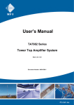
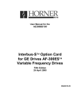
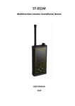
SOLUTIONS FOR THE WIRELESS WORLD SOLUTIONS POUR UN MONDE SANS-FILS Your account representative is: 2010/11 TA B L E O F C O N T E N T S Telecommunications Guisys . . . . . . . . . . . . . . . . . . . . . . . . . . . . . . . . . . . . . . . . . . . . . . . . . . . . . . . . . . . . . . 2 General Purpose Test and Measurement Instruments Rohde&Schwarz . . . . . . . . . . . . . . . . . . . . . . . . . . . . . . . . . . . . . . . . . . . . . . . . . . . . . 3-6 RF Site Measurement Products Bird® Technologies Group – Bird Electronics Brand Products . . . . . . . . . . . . . . . . . . . 7-9 dBm . . . . . . . . . . . . . . . . . . . . . . . . . . . . . . . . . . . . . . . . . . . . . . . . . . . . . . . . . . . . . . . 10 General Dynamics . . . . . . . . . . . . . . . . . . . . . . . . . . . . . . . . . . . . . . . . . . . . . . . . . . 11-12 Bird® Technologies Group – TX RX Systems Brand Products . . . . . . . . . . . . . . . . . 13-18 G-Wave . . . . . . . . . . . . . . . . . . . . . . . . . . . . . . . . . . . . . . . . . . . . . . . . . . . . . . . . . . 19-20 Bird® Technologies Group – TX RX Systems Brand Products . . . . . . . . . . . . . . . . . 21-23 RF Site Management Products Trilogy – RF Cables (PCS, Cellular, Paging Broadcast and Microwave) . . . . . . . . . 24-27 Citel – RF Surge Protection . . . . . . . . . . . . . . . . . . . . . . . . . . . . . . . . . . . . . . . . . . . 28-29 DS3, Dual-DS1 Test Set: Gb310 Quickly monitor, test & verify DS3 & DS1 circuits with this Complete DS3, Dual-Independent DS1 test system. Features Integrated BRICK • • • • • • • • Simple Intuitive Use State-of-the-Art Cellular Backhaul Testing DS3 services testing DS1 or Dual-DS1 testing DS0 E911 Data Activity PRI-ISDN 4-wire DDS Comprehensive DS3 • • • • • • • • Auto, M13, C-bit, UnF B3ZS Line Coding Monitor & TERM modes Internal & Loop Timing ALARM Status & History Qualify DS3 Signal Auto-Frame to T3 circuit DS3 Frequency & Level Dual-Independent T1’s • • • • • • • • Test two (2) T1’s at once! Auto, ESF, D4, Unframed B8ZS/AMI Line Coding Monitor, TERM & Bridged Internal & Loop Timing ALARM Status & History DS1 Frequency & Level DS1 Clocking & Slips Signaling-TIMS Test Set: Gb104 Complete Signaling-TIMS Test set. Simple Graphic User Interface is also available for PC’s, Laptops & PDA’s! Features • • • • • • • Upgrade old HP4935’s CO/PBX Emulation RING & Dial-tone! Wideband Mode Add DS3/DS1/PRI/DDS Rack-mount Version Simple Intuitive Interface with onetouch operation! • • • • • State-of-the-Art Technology Upgraded HP4935A replacement! Voiceband: 600, 900, 1200 ohm Wideband: 100 and 135 ohm CO Modes with internal -48VDC bat, provides Dial-Tone and RINGING! • PBX /Station Emulation Modes • Loop-Start and Ground-Start modes See our web site for a full catalog: www.navair.com 2 • • • • • • • • DID-immediate and DID-wink modes Supports E911 services Real-time Signaling State Display! Monitors Line Voltages and Current Built-in User Manual with HELP & Tips Auto Frequency Sweep to 2MHz! Internal Speaker and Butt-set Jack Rugged Handheld and Rack mount NAVAIR TECHNOLOGIES R&S®FSH4/8 Handheld Spectrum Analyzer Key Features • Frequency range from 9 kHz to 3.6 GHz or 8 GHz • High sensitivity (<–141 dBm (1 Hz), with preamplifier <–161 dBm (1 Hz)) • Low measurement uncertainty (<1 dB) • Measurement functions for all important measurement tasks related to the startup and maintenance of transmitter systems • Internal tracking generator and VSWR bridge with built-in DC voltage supply (bias) • Two-port network analyzer • Easy-to-replace Li-ion battery for up to 4.5 h of operation • Rugged, splash-proof housing for rough work in the field • Easy handling due to low weight (3 kg with battery) and easy-to-reach function keys • Saving of measurement results on SD card • LAN and USB interface for remote control and transfer of measurement data • R&S®FSH4View software for simple documentation of measurement results R&S®FSH3/6/18 Spectrum Analyzer Spectrum analysis anywhere, anytime – on earth and in space The R&S®FSH is the ideal spectrum analyzer for rapid, high-precision, cost-effective signal investigations. It provides a large number of measurement functions and so can handle anything from the installation or maintenance of a mobile radio base station up to on-site fault location in RF cables to development and service – an extensive range of applications. Key Features • Robust edge protection, stable carrying handle • Easy operation • Four hours operating time on battery power • Storage of up to 256 traces and setups • Easy data transfer to PC • High measurement accuracy • Best RF characteristics in its class Keep an eye on it. The R&S®FSL Spectrum Analyzer: to see it is to want it. There are many good reasons to keep an eye on the new R&S®FSL. For one thing, it’s very transportable – at under 17 lbs, compact, and with battery operation, it can quickly turn up in places you might not expect. For another thing, you won’t be the only one who wants to use it. After all, what analyzer in its class gives you an I/Q-demodulation bandwidth of 20 MHz? Or the functions of a high-end box at a midrange price? Or a measurement uncertainty of just <1 dB? And looks this good doing it? None but the R&S®FSL. • FSL-K93 (option) WiMAX Application Firmware for spectrum and modulation measurements on stationary and mobile WiMAX signals. See our web site for a full catalog: www.navair.com • 9 Khz to 3, 6 or 18GHz, with or without tracking generator • Best performance in its class: DANL –142 dBm, IP3 typ. +10 dBm, phase noise typ. –103 dBc • Comprehensive measurement routines: TOI, OBW, Time Domain Power, CCDF, channel/adjacent channel power • LAN interface and USB host adapter • Unique slide-in upgrade design: all hardware options are user-installable without opening the housing Note: there is one vital accessory for your R&S®FSL that we don’t carry. You’ll have to visit the hardware store for that. 3 NAVAIR TECHNOLOGIES RF-Reflection Power Meters Power Meter R&S NRP Key Features Directional Power Meter NAS is the ideal servicing unit wherever power and SWR of all kinds of radio equipment have to be measured. Insertion units for the whole field of mobile radio - including GSM applications – make the NAS a versatile unit and an investment for the future. Key Features • Dynamic range up to 90 dB (sensor dependent) • Level range -67 dBm ... +45 dBm (sensor dependent) • Measurement speed 1500 measurements per second in the buffered mode • Linearity uncertainty 1.5 % (20 to 25°C, f = 100 MHz to 4 GHz) • Precise average power measurements irrespective of modulation type and bandwidth • Up to 4 power sensors on one R&S NRP base unit simultaneously • Flexible measurements on up to 128 time slots per power sensor (26 time slots with base unit) • Direct USB connection from sensor to a PC • S parameter correction of components between sensor and test object • 2 years calibration cycle for base unit as well as for the sensors • Small dimensions (WxHxD) 274 mm x 112 mm x 267 mm • Low weight < 3.0 kg Directional Power Meter NRT Key Features Directional power meters are connected between source and load and measure the power flow in both directions. The power applied to the load and the reflection can thus be measured. URV55 Millivoltmeter Compared to low-cost instruments, power meters like NRT provide a number of benefits: most importantly high measurement accuracy through excellent directivity and a measurement method that determines the average power like a thermal power meter. The instruments thus provide correct measurement results even in case of modulation or in the presence of several carriers. Power Sensors NRT-Z43/-Z44 feature low insertion loss, very good matching and excellent intermodulation characteristics: the signal to be measured is virtually unaffected, the sensor is fully transparent. Key Features Millivoltmeter URV55 is suitable for voltage measurements up to 3 GHz as well as for power and level measurements up to 40 GHz. Thanks to probes with calibration data memory and temperature sensors, which make adjustments by the user superfluous, URV55 provides at all times high-precision measurements free of operator’s errors. NRVD Power Meter RF & Microwave NRP-Z Smart Sensors Key Features NRVD functions like two independent NRVS power meters in one enclosure performing simultaneous measurements and exchanging data with each other. The two channels can be set separately so that two completely different measurements can be carried out at the same time. The two measured values can also be related to each other for readout of reflection coefficient, SWR or return loss, for instance. See our web site for a full catalog: www.navair.com Key Features • Precise average power measurements • Direct USB connection to PC or other Rohde & Schwarz instruments • S Parameter correction of components between sensors and test devices • Flexible measurements on up to 128 time slots per power sensor • 2 year calibration cycle 4 NAVAIR TECHNOLOGIES Analog & Vector Signal Generators ZVL Vector Network Analyzer The cost-efficient compact class in network analysis •Frequency ranges from 9 kHz to 3 GHz/6 GHz/13.6 GHz • Wide dynamic range: >115 dB, typ. 123 dB • Bidirectional test set: display of all four S-parameters • 75 Ω version from 9 kHz to 3 GHz for TV/CATV • Complete spectrum analyzer as an option • Compact size and low weight (<7 kg) • Digital communications standards • Accurate power measurement (USB connector for R&S® NRP-Z power sensor series) • Compact size and low weight (<7 kg) • 12 V DC operation and internal battery • Connection for external monitor The New Standard of Excellence in Analog Signal Generation R&S®SMA100A The R&S®SMA100A combines superior signal quality with a very high setting speed, making it the ideal generator for any task in development, production, service or maintenance. Setting Standards in Mid-range Analog Signal Generation R&S®SMB100A The R&S®SMB100A sets new standards in its class due to its outstanding characteristics. The instrument combines excellent signal quality with very high output power, which makes it ideal for any task. Key Features • Frequency range from 9 kHz to 3 GHz or 6 GHz with or without an electronic attenuator • CW signal and all common types of analog modulations (AM, FM, φM, PM) • Very low phase noise • High power output as standard • Optional removable mass memory card Key Features • Frequency range from 9 kHz to 1.1 GHz, 2.2 GHz, 3.2 GHz or 6 GHz • Best signal quality in its class • 3 year calibration cycle • Highest output power in its class • All-purpose RF source Best Price/Performance Ratio and Key Features • Frequency range from 9 kHz to 1.1 GHz Smallest Size in its Class R&S®SMC100A The R&S®SMC100A is the newest analog signal generator that Rohde & Schwarz has to offer. It has a very small size and is priced very attractively to reduce overall total cost of ownership. See our web site for a full catalog: www.navair.com 5 or 3.3 GHz • Outstanding signal quality • All analog modulation types and high output power as standard • Electronic attenuator • Low phase noise and fast switching time NAVAIR TECHNOLOGIES Analog & Vector Signal Generators Generating Signals for Today and Tomorrow R&S®SMBV100A The R&S®SMBV100A is a state-of-the art vector signal generator that has been designed with a future-proof hardware concept. Compact, cost-effective measuring receiver R&S®ESL EMI Test Receiver The R&S®ESL EMI test receiver combines two instruments in one, measuring EMC disturbances in accordance with the latest standards and also serving as a full-featured spectrum analyzer for diverse lab applications. The R&S®ESL is the ideal instrument for small budgets. Key Features • Frequency range from 9 kHz to 3.2 GHz or 6 GHz • Excellent characteristics and high output power as standard • Wide RF signal bandwidth of up to 120 MHz with internal signal generation • Maximum supported external RF bandwidth is 500 MHz • Supports all of the important digital standards available now such as WiMAX, 3GPP and LTE, as well as any future digital standards still in development Key Features • Frequency range from 9 kHz to 3 GHz or 9 kHz to 6 GHz covering almost all commercial EMC standards • First-ever combination of an EMI test receiver and spectrum analyzer in the entry-level class • All major functions of an advanced EMI test receiver, including fully automated test sequences • Weighting detectors: max./min. peak, average, RMS, quasi-peak as well as average with meter time constant and rms-average in accordance with the latest version of CISPR 16-1-1 • Compact, lightweight instrument, can be batterypowered for mobile applications R&S®HE300 Active Directional Antenna 20 MHz (optional 9 kHz) to 7.5 GHz Key Features The practical and very wideband R&S®HE300 active directional antenna locates transmitters and interference sources when combined with portable receivers (e.g. the R&S®PR100). • Very wideband performance in a practical size Three exchangeable antenna modules that are supplied with the antenna cover the 20 MHz to 7.5 GHz frequency range. An additional module (R&S®HE300HF for 9 kHz to 20 MHz) is available as an option. • Unambiguous radiation pattern • Direction is found by orienting antenna toward maximum field strength • Low weight, due to optimized selection of materials, ensures fatigue-proof handling • Horizontal and vertical polarization • Wide dynamic range • Passive antenna if amplifier is switched off The modules can be plugged into the handle with the correct orientation for vertical or horizontal polarization and then mechanically locked in place. A built-in, low-noise wideband amplifier can be activated to enhance system sensitivity (active mode). In passive mode, the amplifier is bypassed so that the R&S®HE300 can also be used in the vicinity of strong signal sources. See our web site for a full catalog: www.navair.com 6 NAVAIR TECHNOLOGIES SignalHawktm SIGNALHAWKTM VNA | Spectrum Analyzer with Power Meter Option MODEL SH-362S: Spectrum Analyzer & 2-Port VNA MODEL SH-361S: Spectrum Analyzer & 1-Port VNA MODEL SH-362: 2-Port VNA (325MHz to 3.6GHz) MODEL SH-36S: Spectrum Analyzer (100kHz to 3.6GHz) Bird Technologies SignalHawkTM Analyzes radio frequency spectrum. Measures intended and interfering signals. Allows setup of parameters such as frequency, amplitude, and markers. Graphically displays signal amplitude vs. frequency and saves traces. KEY FEATURES • Fast, Accurate, and Sensitive: -42 dB Directivity and-135 dBm Noise Floor • Large High-Resolution Display: Full Color, Indoor/Outdoor Viewable • Easy-to-Use: Intuitive Menus, One-Button Setup, and On-Board Help • Long Battery Life: 5.5 Hours per Charge, Field Replaceable Battery • Rugged: Drop Tested per Military and European Standards • USB Connectivity: USB Drive Stores 90,000 Traces • Spectrogram • GPS • Power measurement interface • Internal Bias – Tee Model SH-36S SignalHawkTM ALSO AVAILABLE Bird®Rack-Mount SignalHawkTM Spectrum Analyzer Model SH-36S-RM: 100kHz to 3.6 GHz Remotely analyzes the radio frequency spectrum. From your office: measures intended and interfering signals, allows setup of parameters such as frequency and amplitude markers. Also, remotely displays signal amplitude vs. frequency and saves traces to your PC. Bird®PC SignalHawk Spectrum Analyzer Model SH-36S-PC: 100kHz to 3.6 GHz Analyzes the radio frequency spectrum. Measures intended and interfering signals, allows setup of parameters such as frequency and amplitude markers. Also, displays signal amplitude vs. frequency and saves traces on your PC. WORLDWIDE APPLICATIONS Cellular, PCS, DCS, 2G, 3G, 4G, CDMA, cdmaOne, CDMA 2000, 1x, 1x EV-DO, GSM, GPRS, EDGE, UMTS, HSDPA,W-CDMA, TDMA, AMPS 802.11, Bluetooth, Broadcast, Emergency, Fire, GPS, HDTV, IBOC, In-Building, Lab, Microwave, NPSPAC, Paging, Police, Private, Project 25, Public Safety, Tactical Military, Telematics, Tetra, Trunking, Utilities,WiMAX,WLAN and WLL. See our web site for a full catalog: www.navair.com 7 NAVAIR TECHNOLOGIES NEW Bird® Model 5000-XT Hand-Held Digital Power Meter The hand-held digital power meter has been completely redesigned with the new Bird® 5000-XT. Ideally suited for field techs and engineers who need to make power measurements anywhere they go, the 5000-XT’s new user interface has an intuitive, menu-driven design, making it the easiest to use on the market. It’s operable even with one hand and compatible with all our field and legacy sensors. Bird AT Series AT-500 & AT-800 R ® Bird AT Series AT-500 & AT800 Antenna Testers Antena Testers The Bird AT-Series Antenna Testers provide a cost-effective, fast, graphical way of determining the quality of mobile and base station antennas. • Rugged, easy-to-use, hand-held design with extended battery life makes it ideal foruseinthefield. •TeststhesysteminVSWR,ReturnLoss,MatchEfficiency,orReflection Coefficient(Rho) • Single frequency readings and frequency sweeps allow for everything from pinpointests to system optimization and tuning. • Can save up to 12 traces for comparison and tracking over time • RS232 Interface allows communication with a PC for saving traces using the optional software. Frequency Characteristics: Frequency Range AT-500 2 to 520 MHz AT-800 806 to 960 MHz Frequency Resolution 20 kHz Frequency Accuracy 50 kHz ® Number of points 100 BIRD ANTENNA & CABLE MONITOR General Requirements: Dimensions8”x4-5/8”x1-3/4”(204x118x42mm) Minimize Weight 2.0 lbs (0.9 kg) Downtime Temperature, Operating 0 to 50 C (32 to 122 F) Keep Your Critical Antenna Sites Temperature, Storage -40 to +71 C (-40 to +160 UpF)& Running Humidity 95% 5% max (noncondensing) Compliance Unit complies with MIL-T-28800 Class 5 except for temperature and humidity. Unit is CE-compliant and RoHS compliant. Bird Antenna ® Cable Monitor Accurately detects antenna system degradation and failures Measurements: Rho 0.000 to 1.000 • Compatible with analog 0ortodigital Match Efficiency 100%cellular and two-way radio systems • Worldwide applications Return Loss include -32 to 0Tetra, dB Cellular, PCS and many others 1.00 to 100.00 • Monitors VSWRVSWR and power levels and provides alarm outputs Accessories: • Sensitive toAccuracy antenna faults internal transmitter VSWR monitors may not detect Measurement Rhothat 0.04 Antenna & Interseries Adapter, N (M) 4240-402 Match Efficiency Calculated from Cable Monitor • Local or remote operation via PC software PC Software Tool 4240-403 Interseries Adapter, N (F) Loss applications Rho accuracy 7005A970 • Ideal forReturn multi-carrier (OptionalBNC Accessory) 4240-404 Interseries Adapter, (M) VSWR Test Port: 4240-405 Interseries Adapter, BNC (F) Connector N(F) supplied. N, TNC, UHF, BNC, male 4240-406 Interseries Adapter, TNC (M) 8 See our web site for a full catalog: www.navair.com or female available 4240-407 Interseries Adapter, TNC (F) VSWR 1.25 max 4240-408 Interseries Adapter, UHF (M) NAVAIR TECHNOLOGIES NEW Bird®Wideband Power Sensor 5012A, 5016, 5017 Bird’s® Wideband Power Sensor (WPS) never requires field calibration, only requires calibration once per year and is traceable to National Institute of Standards and Technology (NIST). The WPS measures True Average Power, Peak Power, and Duty Cycle directly with exceptional accuracy and uses these precise measurements to calculate a wide range of other important factors, such as VSWR, Return Loss, Reflection Coefficient, Crest Factor, Average Burst Power, and CCDF. PROBLEMS Downtime is necessary Have analog, digital, and multi-carrier signals to measure Tight budgets Varying field tech skill levels Need greater confidence in measurement SOLUTIONS - Monitor and perform maintenance for monitoring while DUT is in-service - Measure forward and reflected power to troubleshoot system failures - Modulation independent measurements - USB connectivity, no meter required - Complimentary Virtual Power Meter (VPM2) software - Sensor plugs and plays with 5000-XT meter - No field calibration required - NIST traceable calibration APPLICATIONS WPS measures: Analog Cellular, Digital Cellular, 3G, 4G, Tetra, APCO/P25, Trunking, CDMA, TDMA, WCDMA, GSM, Transportation, Tactical Military, Radar, Avionics, Marine, LMR, Analog Broadcast, Digital Broadcast, GSM, GPRS, EDGE, UMTS, HSDPA, Bluetooth, Fire, GPS, NPSPAC, Paging, Project 25, Public Safety, Telematics, Utilities, WIMAX and WLAN. Measurements performed: Peak power, true average power and Duty Cycle. Calculations Performed: VSWR, Return Loss, Reflection Coefficient, Crest Factor, Average Burst Power and CCDF. Site Analyzer EX Series SA-6000EX (25-6000 MHz) SA-2500EX (780-2500 MHz) SA-1700EX (25-1700 MHz) SA-1700EXP (25-1700 MHz) • ONE UNIT covers the entire 25-6000 MHz range! • Easy to operate and field ready for first-time, occasional and experienced users • Suitable for use in Worldwide Cellular and PCS/DCS systems; supporting measurement of CDMA, GSM, TDMA and AMPS modulation schemes • Other applications include 3G, Broadcast, Government, Tactical Military, Microwave, Paging, Public Safety, Trunking, WLAN and WLL, and TETRA. See model matrix below • Color display is clearly visible in direct sunlight • With a single download you can view data as Distance to Fault or Measurement Match-no need to store two traces. • FDR (Frequency Domain Reflectometry) measurement method results in a highly reliable assessment of the health of critical components in your system; ultimately providing a “heads-up” before a failure occurs • Fault location or DTF mode indicates VSWR or Return Loss levels at each point along the cable and antenna system length • Cable Loss function measures insertion loss of the cable system over a given frequency range Model # Frequency Range Frequency Resolution Power Measurement Return Loss site for See our web Test Port Impedance SA-1700EX SA-1700EXP SA-2500EX SA-6000EX 25-1700 MHz 25 kHz; 25-800 MHz 50 kHz; 800-1700 MHz 25-1700 MHz 25 kHz; 25-800 MHz 50 kHz; 800-1700 MHz 780-2500 MHz 50 kHz No Yes Yes 25-6000 MHz 25 kHz; 25-800 MHz 50 kHz; 800-2500 MHz 150 kHz; 2500-6000 MHz Yes a full catalog: www.navair.com 9 0 to -60 dB N-type female connector 50 NAVAIR TECHNOLOGIES Carrier to Noise Generator CNG-70/140 RF Converter Series UDC-172-302-2 APPLICATIONS: • Bit error rate/SINAD testing • SATCOM modems • Channel impairment tests • Development, qualification, and verification testing • Manufacturing test APPLICATIONS: • A laboratory workhorse • Programmable LO for frequency converters • Frequency hopping source • RF device characterization • Tracking generator source FEATURES: • C/N, C/No, Eb/No, and C/I modes • 1 or 2 independent RF channels • Continuous input power monitoring • Un-interrupted signal path during calibration cycle • IEEE-488.2 and RS-232 interface • Easy to read VFD display FEATURES: • Low noise (-103 dBc/Hz 1 kHz offset @ 1GHz) • Fast switching (<2msec typ.) • Small and lightweight (10” x 10” x 3”) • Non-volatile memory for storage/recall of instrument settings • IEEE-488.2, LAN, and RS-232 interfaces standard OPTIONS: • Fast switching speed (200 usec) • File driven hopping/swept frequency mode Satellite Link Emulator SLE700 Precision White Gaussian Noise Generator APPLICATIONS: APPLICATIONS: • Earth terminal testing • Satellite payload testing • Satellite system integration test beds • Mobile transceiver testing • Bit error rate (BER) and SINAD testing • Component and subsystem linearity characterization • Wireless link emulation FEATURES: • Calibrated noise density over entire operating frequency • Noise power/bandwidth and noise density control • Solid state noise attenuator with 0.0156 dB resolution • IEEE-488.2 interface FEATURES: • Precision Test Models Test scenarios are user-defined, based on ephemeris data or satellite orbit models. • Multiple Orbit Models Emulates earth-to-satellite-to-earth, or earth-to-satellite links; Low Earth Orbit; Medium Earth Orbit, Geostationary and Geosynchronous • Two Operating Modes In Static mode, link parameters are set to fixed values. In Dynamic mode, data files are used to vary the link parameters in real time. See our web site for a full catalog: www.navair.com 10 NAVAIR TECHNOLOGIES The R2600 Series: The industry proven test solution for APCO™ Project 25 SMARTNET/ SmartZone®, ASTRO®, SECURENET®, and conventional two way radio. NEW General Dynamics R8000 Radio Communications Analyzer The R2600 family of Communications System Analyzers performs tests normally associated with these instruments: • The R8000 Radio Communications Analyzer utilizes leading-edge software defined radio technology to deliver previously unimaginable results: • A truly portable instrument with more functions than today’s bench top analyzers. • Weighing only 14 pounds, the R8000 gives service technicians power and flexibility not previously available in this type of instrument. • This, combined with the instrument’s feature-packed spectrum analyzer, makes the R8000 ideal for taking to sites for infrastructure maintenance and interference measurement. • The instrument’s bright 8.4” color LCD screen is well visible in sunlight and features wide viewivng angles. MORE • RF Signal Generator • Sensitive Measurement Receiver • Spectrum Analyzer • Full Band Duplex Offset Generator • Frequency Counter • AC/DC Voltmeter • 50 kHz Oscilloscope • RF Wattmeter • Signal Strength Meter • Frequency Error Meter • SINAD Meter • Distortion Meter • Sweep Generator • Audio Generator • Modulation Analyzer • Signaling Simulator • RF Scan/Counter • High Performance Spectrum Analyzer with Markers NEW P-25 Performance The R8000 is the worlds first truly portable test set and delivers fully functional P-25 test capability. The R8000’s P-25 test suite includes: • Patented Voice Playback Test • Generate/Receive V.52 (0.153) test pattern BER test • Generate/Receive 101Hz test pattern BER test • Power Meter • Frequency Error • Modulation Fidelity • Symbol Deviation • Eye test pattern • C4FM generate capability Optional in R2600 & R2625; standard in R2670: • Cable Fault Locator • Tracking Generator • Programmable Test Set-Ups APCO is a registered trademark of the Association of Public Safety Officials ASTRO, SECURENET and SMARTNET/SAMARTZONE is a registered trademark of Motorola Inc. See our web site for a full catalog: www.navair.com 11 NAVAIR TECHNOLOGIES R2660 iDEN™ Digital Communications System Analyzers R2600D – For Conventional Radio and Paging Service FEATURES: • RF Signal Generator • Sensitive Measurement Receiver • Spectrum Analyzer • Duplex Offset Generator • Frequency Counter • AC/DC Voltmeter • 50 kHz Oscilloscope • RF Wattmeter • Signal Strength Meter FEATURES: • Average power meter • Frequency error meter • SQE (Signal Quality Estimate) • Tracking generator • Cable fault locator • High stability oscillator • Enhanced spectrum analyzer with markers • Test memory presets • BER (Bit Error Rate)In addition to offering all the standard system features, the R2660 also includes several high performance features for testing more sophisticated systems. R2660 Standard System Capabilities iDEN-Specific Test Capabilities • Supports both 6:1 and 3:1 TDMA format • Subscriber unit testing in dynamic call simulation mode including vocoder for live voice testing • Subscriber unit testing in test mode • Base site transmitter testing under operating conditions • Base site receiver BER testing General Diagnostic Features • • • • • • • • Frequency Error Meter SINAD Meter Distortion Meter Sweep Generator Audio Generator Modulation Analyzer Signaling Simulator RF Scan/Counter R2680 – MPT1327 Trunking Communications System Analyzer MPT1327 Test Parameter Entries: (Dependent on Test Selection) • Signaling Type • System ID • Control Channel Number • Traffic Channel Number • Call Sequence • Emergency Priority • Call Set-up R2670B Communications System Analyzer Radio and Paging Service • Radio ID2 (for System Initiated Tests) • Group ID • Group Call Type • Status Code • Data Codewords • Signaling Parameters FEATURES: • Both VSELP and IMBE compatible vocodes • SMARTNET/SmartZone Type 1,1}Ipe I EP II,1}Type II) • SECURENET Secure Voice • Multiple encryption formats: AES, DES, DES-XL, DES-OFB, DVI.XL & DVP-XL • Programmable with compatible KVL – no need to only utilize the built-in test keys • ASTRO trunking with! both VSELP and IMBE vocoders • Project 25 digital trunking with support for Linear Simulcast Modulation (LSM) -flash upgrade to system release 6.1 coming soon. The R2670 can stand up to heavy field use with a proven 33,000 hour MTBF, and a choice of AC, DC, or battery operation. See our web site for a full catalog: www.navair.com 12 NAVAIR TECHNOLOGIES RF INFRASTRUCTURE PRODUCTS Broadband RX Antenns 700/800 MHz T-Pass TX Combiner Tower Top Amplifier Repeater #1 Broadband TX Antenns Repeater #2 Repeater #3 Repeater #4 Repeater #5 792-824 MHz Preselector 746-901 MHz Receive Multicoupler COMPLETE SYSTEMS SOLUTIONS Multiband Shorthaul Control Station Combiner 43-05-01 Series BTG, TX RX System multi-channel multi-band combiners provide frequency-agile operation across multiple bands. Interoperability can be combined into a single network for efficiency. PROBLEMS SOLUTIONS Many bands on site with frequencies from VHF to 900 MHz - Multiband combiner allows operation in multiple bands Standardization across all sites - Advance coupler technology with no need for tuning — control stations can be connected without regard to frequency Space constraints Cost reduction - Low Profile for space efficient installation - Multiple bands can utilize the same combiner for cost reduction APPLICATIONS Control Station Combiners operating in multiplebands may be used to reduce the number of antennas required on a communications site while also ensuring that predictable radio-to-radio isolation is maintained at all times — irrespective of individual radio’s Tx or Rx operating mode or antenna isolation characteristics. Is ideally used with multiband coupler Bird®SB I Series Signal Boosters 62-89B, 62-90A Series NPSPAC Bird Technologies Group, TX RX Systems brand, SB I Series family of signal boosters provides an exceptional balance of performance and value for extended coverage of radio communications networks. PROBLEMS SOLUTIONS RF coverage is required for different building sizes and configurations - Bird® SB I is available in two output power models: System monitoring is required - High power model (+35 dBm) Need to eliminate potential interference and unwanted coverage - Low power model (+25.5 dBm) Reliable in-building communications is a must - Alarm and sampler port are available - Gain is adjustable from 0 to 30 dB in 2 dB increments - Bird invented the signal booster and has been a leader in providing reliable inbuilding wireless solutions since 1980 APPLICATIONS Cost effective in-building coverage solutions for applications in critical communications systems Public Safety, Private Wireless networks Excellent selectivity for operation in a shared frequency band See our web site for a full catalog: www.navair.com 14 NAVAIR TECHNOLOGIES Bird®SB I Series Signal Boosters 62-83E-Series Dual Band 700/800 MHz Bird Technologies Group, TX RX Systems brand, SB I Series family of signal boosters provides an exceptional balance of performance and value for extended coverage of radio communications networks. PROBLEMS SOLUTIONS RF coverage is required for different building sizes and configurations - Bird SB I is available in two output power models: System monitoring is required Need to eliminate potential interference and unwanted coverage Reliable in-building communications is a must Need to provide coverage for both 700 MHz and 800 MHz - High power model (+34 dBm) - Low power model (+25.5 dBm) - Alarm and sampler port are available - Gain is adjustable from 0 to 30 dB in 2 dB increments - Bird invented the signal booster and has been a leader in providing reliable inbuilding wireless solutions since 1980 - SB I dual band provides coverage of both frequencies in one unit APPLICATIONS Cost effective in-building coverage solutions for applications in critical communications systems Public Safety, Private Wireless networks Excellent selectivity for operation in a shared frequency band Bird®SB I Series Signal Boosters 62-91-Series Cellular A, B, & A/B Bands Bird Technologies Group, TX RX Systems brand, SB I Series family of signal boosters provides an exceptional balance of performance and value for extended coverage of radio communications networks. PROBLEMS SOLUTIONS RF coverage is required for different building sizes and configurations - Bird SB I is available in two output power models: System monitoring is required - High power model (+34 dBm) Need to eliminate potential interference and unwanted coverage - Low power model (+25.5 dBm) Reliable in-building communications is a must - Alarm and sampler port are available - Gain is adjustable from 0 to 30 dB in 2 dB increments - Bird invented the signal booster and has been a leader in providing reliable inbuilding wireless solutions since 1980 APPLICATIONS Cost effective in-building coverage solutions for applications in critical communications systems Coverage of full Cellular A/B bands or each band individually Excellent selectivity for operation in a shared frequency band See our web site for a full catalog: www.navair.com 15 NAVAIR TECHNOLOGIES signal booster II Signal Booster II 800 MHz Series 800 MHz-Series Mission Critical Reliability for In-building Coverage . . . The New Signal Booster II provides Public Safety grade reliability and coverage in disadvantaged RF locations for First Responders, Public Safety/Governmental agencies and Private System Users. Reliable RF coverage is gained in basements, parking garages, correctional facilities, courthouses, hospitals, malls and schools. Other challenging environments covered by the Signal Booster II product include subways and rapid transit systems, airports, stadiums/ arenas, high-rise buildings and large private enterprise facilities and campuses. Whether you are on the front line and depend on a reliable communication system or you are the systems integrator responsible for implementing a dependable system, this new compact design facilitates installation and system optimization for rock solid operation via a simple man-machine interface. Imbedded features for ease of initial setup include decoupled test points for signal level detection, menu driven gain setting, front panel LED monitors for amplifier and power status, and an at-a-glance LED bar graph to indicate relative level of Output Level Control (OLC). Additionally, this product offers a unique on-board OLC DataLog feature that archives a User Signal Profile to facilitate optimum system configuration and performance. Microprocessor Controlled Fault Monitoring and Alarming Ensures Reliable Operation and Flexible Configuration Output Level Control (OLC) Circuit Monitors and Controls RF Output Power • Maintains maximum required output power while preventing damage and excessive emissions per FCC requirements • Easy-to-read LED bar graph • Unique OLC DataLog feature facilitates system maintenance and optimization • Control system continuously monitors parameters including voltage, current, temperature and OLC activity • LEDs on each module quickly annunciate source of fault • Simple, back-lit liquid crystal display (LCD) and switch control • Fault triggers annunciation on panel, alarm contact closure and internal recording of failed subsystem Decoupled RF Test Points For Simplified Service • Allow fast system measurements in both uplink and downlink directions • Monitor signals for performance optimization • Integrated design facilitates non-intrusive measurements Secure, Non-Vented NEMA Enclosure Suitable for Extreme Indoor and Outdoor Environments • Configured to customer requirements and addresses many specifications requiring custom passbands • Models available with passbands that range from 3 MHz (NPSPAC with excellent out-of-band rejection) to 18 MHz for full band coverage • No Tools Required Programmable Gain Setting Optional Features Available • Ease of initial configuration via front panel • When used in conjunction with OLC DataLog, simplifies post Comm Card II for remote communications and control Fiber optic link interface Redundant PA configuration -48 VDC input installation adjustments Three Major Gain Ranges Available DC Backup Interface Accepts +24 to +30 VDC and optional -48 VDC NEW • Easy “slide-in” replacement process • Facilitates ease of service and system configuration High Performance Bandpass Filters Simple Setup is Achieved Via an Integral, ManMachine Interface • • • • Card Cage Modularity Low:+ 45 dB, Medium:+ 60 dB, High:+ 80 dB All Signal Booster II products comes with a 5 year OEM warranty See our web site for a full catalog: www.navair.com 16 NAVAIR TECHNOLOGIES Bird®Channelized Signal Booster Model 611-70-Series Bird Technologies Group (BTG), TX RX Systems Channelized Signal Booster operates in the 450-512 MHz range available in 1-30+channels. Intuitive user interface allows booster to be easily configured for changing RF environments. Channel bandwidth isuser selectable (12.5, 25, and 50 kHz standard or custom).Tone squelch capability is also available and individually configuredper channel. PROBLEMS SOLUTIONS Noise and Interference that cause communication problems in a crowded spectrum. - Channelized booster amplifies narrow band channels. Amplifying only the desired spectrum prevents interference to other users. Changes in RF environment - Modular design facilitates fast and easy reconfiguration, expansion, and redundant capability. Userinterface also provides maximum flexibility to mplement changes to the system such as output power, center frequency, filter shape, and group delay. System coverage is difficult to assess Bird® Compact Ceramic TX Combiner APPLICATIONS Cost effective in-building coverage solutions for applications in critical communications systems Public Safety, Private Wireless networks Excellent selectivity for operation in a shared frequency band NEW BTG, TX RX System brand UHF Ceramic TX Combiner combines up to 6 transmitters onto a single antenna. With a footprint that’s more than 50% smaller than comparably performing 10” cavities. This optimizes valuable space for your radio equipment, which in an era of escalating lease costs, makes it the perfect solution for expansion. And because of our modular design, you can purchase in single-channel increments. Plus, it delivers the kind of high performance and minimum interference you’ve come to expect from Bird®. PROBLEMS SOLUTIONS May need to minimize the number of antennas at a communication site - Can combine up to six transmitters onto a single antenna which efficiently utilizes valuable rack and shelter space Need to maintain or minimize additional costs associated with space in a radio shack / transmitter shelter Need to minimize interference with competing communication systems And may lack the time or expertise to integrate the solution into the overall radio system - Our units provide valuable real estate in small shelters where traditional T-Pass combiners are too large - System-level signal analysis (including interference mitigation) for each customer application - Offer complete solutions from system design through individualized configurations, installation support, and maintenance programs. See our web site for a full catalog: www.navair.com 17 APPLICATIONS Any communications system installation whereyou need to reduce the number of antennas on atower. Any communications system designed to minimize tower size and maximize site space Secured applications that require equipmentunder lock and key NAVAIR TECHNOLOGIES Tower Top Amplifier System 429-83H-01-T & 429-83H-01-M Tower Top Amplifier System 429-83H-01-T & 429-83H-01-M The new compact Tower-Top Amplifier (TTA) system is a high performance, quadrature-coupled low noise amplifier (LNA) designed to increase the performance of a Base Transceiver Station (BTS) while ensuring reliable communications for critical Public Safety applications. This increase in sensitivity can make up for the imbalance between mobile and handheld users in critical systems. The TTA system consists of two components: the Tower-Top Amplifier mounted close to the antenna and the Receiver Multicoupler base unit. To reduce the size of the TTA and simultaneously provide 120 dB of isolation of a TX carrier, filtering has been split between the TTA and the base unit. Two independent LNA’s, each powered by separate bias circuits, provides component redundancy as well as excellent intermodulation (IM) performance. Microprocessor-controlled fault detection circuitry provides continuous monitoring and switching of each quad-LNA while sending operational data to the base unit for at-a-glance status reporting and form C contact alarm switching. For AISG/EIA-485 data communications between the TTA and base control unit, a custom PolyPhaserTM lightning protector and a CAT-5E cable are installed at the transmission lines building entry-point ground plate. The surge protector not only passes the DC current that powers the TTA but also generates the low frequency subcarrier for AISG/EIA-485. If the data cable is damaged, removed or not installed, the TTA will continue to operate however, the status and alarm functions will not be available at the base. For testing and diagnosing problems on the main receive line, a test transmission line is required. The system will continue to operate if the test line is damaged or not installed however, an alarm will be continuously set. Features: The TTA System consist of two components: Receiver Multicoupler & Tower Top Amplifier • Redundant quadrature LNA’s and automatic solid-state back-up switching ensures reliable communications • PolyPhaserTM impulse suppressors provide protection from lightning damage on all I/O ports • AISG/EIA-485 compatible for data communications between TTA and Receiver Multicoupler • RF test port enables gain, sensitivity and desensitization measurements from ground level • Compact, weather-resistant stainless steel modified NEMA 4X enclosure • Webpage user interface available for controlling and monitoring of amplifier currents, alarms and attenuators • One rack-unit high Receiver Multicoupler (MCU) • Multifunction LCD readout with multicolored LEDs for status reporting • Form C contacts for fault reporting through a supervisory system • Ethernet connector for fast ATP mode switching and alarm details System Specifications Combined Tower Top and Base Deck Filter Response ATTENUATION (dB) 0 13 dB net gain and maximum 6 dB transmission line loss assumed -20 Bandwidth 792-824 MHz -40 System Noise Figure 2.9 dB Typ, 3.5dB Max -60 3rd Order IIP > 15 dBm -80 TTA Net Gain Fully settable by electronic attenuator Rejection 110 dB min, 120 dB nominal at 776 and 851 MHz Net Weight 30.5 lbs for TTA + MCU Ship Weight 42 lbs -100 -120 -140 -160 -180 760 780 800 820 840 860 FREQUENCY (MHz) A steep skirted TEM bandpass filter in the tower box augmented by a ceramic filter in the base unit provide a selective 32 MHz system window. Product Description Part Number TTA, 792-824 MHz, tower top box only 429-83H-01-T Receiver Multicoupler for TTA, 16-port, 792-824 MHz, to be used in conjunction with 429-83H-01-T, 90-240 VAC 429-83H-01-M Receiver Multicoupler for TTA, 16-port, 792-824 MHz, 48 VDC 429-83H-01-M-48 Bird® Technologies Group combines the industry leading brands of both Bird Electronic and TX RX Systems and is a global, innovative supplier of RF products, systems, services and educational solutions. Bird® Technologies Group reserved the right to modify specifications or discontinue any product without notice. 18 See our web site for a full catalog: www.navair.com440.248.1200/866.695.4569 www.bird-technologies.com [email protected] NAVAIR 661-CTAS-DS10212008 TECHNOLOGIES BDA-XXXX-0.5/0.5W-70-A Indoor MINI BDA’s for any 760-960 Bands and PCS / DCS/UMTS/AWS with 0.5W Uplink and 0.5W Downlink (@ 1 dB), and 70dB Gain. Units feature extremely low Noise Figure,Gain and a wide dynamic ALC range. The design is based on a duplexed path configuration with sharp out of band attenuation allowing an improved isolation between the receiving and transmitting paths. These products are the most economical solution for several story buildings with weak signal strength outside the covered structure. Local Visual Alarm indication and Remote alarm interface via D-Sub 9-Pin connector and pigtail are optional. Frequency Band Any Cellular Any Public Safety Any PCS or DCS* or UMTS/AWS Full Band PCS, DCS, UMTS or AWS *NON Contiguous Any Dual Band BDA-XXX-1/1W-80-AB BDA-XXX1/10W-80A B BDA-XXX-1/25W-80-A B Indoor BDA’s for any 760-960 Bands and PCS/DCS/UMTS/ AWS with 1 or 2W Uplink and 1W, 2W, 10W, 25W Downlink (@ 1 dB), and 80dB Gain. Units feature exceptionally low Noise Figure and a wide ALC dynamic range. Options: • 2W uplink or 2W downlink, • External filter capability. • Remote Monitoring Option • 19” rack • S1 – Battery Charger in BDA for External Backup • 90+ dB gain Frequency Band SMR or ESMR800 or SMR900 Any Public Safety* Any Cellular Any GSM Any PCS/DCS/UMTS/AWS Full Band PCS, DCS, UMTS or AWS Dual Band SMR800/900 Dual Band CELL/PCS Dual Band Public Safety *Full Band or NON Contiguous PCS/DCS ANY CELL ANY PCS BANDS Indoor BDA’s for any 760-960 Bands and PCS/DCS/UMTS/ AWS with 1 or 2W Uplink and 10W or 25W Downlink (@ 1 dB), and 80dB Gain. Units feature exceptionally low Noise Figure and a wide ALC dynamic range. Options: • 2W uplink /10W downlink • External filter capability • Remote Monitoring Option • 90+ dB gain • 19” rack • S1 Version – including Battery Back Up Charger ( not the battery pack). Frequency Band SMR or ESMR800 or SMR900 Any Public Safety* Any Cellular Any GSM Any PCS/DCS/UMTS/AWS Full Band PCS, DCS, UMTS or AWS Dual Band SMR800/900 Dual Band CELL/PCS Dual Band Public Safety *NON Contiguous PCS/DCS BDA-XXXX-1/10W-80-O or BDA-XXXX-1/25W-90-O BDA-XXXX-1/50-90-O Outdoor BDA’s for any 760-960 bands and PCS/DCS/ UMTS/AWS with 1 or 2W uplink and 10W or 25W downlink (@ 1 dB), and 90dB gain. The units are built in NEMA 4 enclosures, to withstand the outside environment. All units come with standard AC line Surge protection and local visual alarm indicators. Options: • 2W uplink • Remote monitoring 7 pin connector and Pigtail • External 28 VDC for Battery backup • 90dB gain – for 10W system • Complete UPS. . See our web site for a full catalog: www.navair.com 19 Frequency Band SMR or ESMR or SMR900 Public Safety ANY CELL ANY GSM ANY PCS/ DCS/UMTA/AWS DUAL BAND SMR 800/900 *Non Contiguous CELL ( A+A’ or B+B’) *Non Contiguous DCS or PCS or UMTA /AWS NAVAIR TECHNOLOGIES BDA-UHF or CDMA450-4/4W-70-A and BDA-UHF or CDMA450-4/4W-55-AB UHF,TETRA or CDMA450 BDA’s with 4W uplink and 4W downlink (@1dB) , and 70dB or 55dB gain. Options: Frequency Band UHF/ CDMA 450, 55 dB gain UHF/ CDMA 450 , 70 dB gain • Standard Separation for UHF and CDMA 450 are defined as “Corner to Corner”. Should you require special non standard separation please contact us for availability. • Visual Alarm option • Remote Monitoring Option (with Visual Alarm option) • NEMA 4 for Indoor and Outdoor LINE EXTENDER -BDA-XXXX-0.15/0.15W-35-E or A LINE EXTENDER/BDA’s for CELL or PCS with 0.15W Uplink and 0.15W Downlink (@ 1 dB), and 35dB Gain. In-Line Bi-Directional Amplifiers (Extenders) were designed as Bi-Directional Line Amplifiers for use in Distributed Antenna Systems (DAS) to compensate for cable loss on long cable runs. Extenders are used as indoor repeaters with external AC/DC converters or as In-Line amplifiers when DC power is injected through the BTS port as an option. Options: • Visual Alarm • Remote Monitoring Via 9 Pin Connector and pigtail. • NEMA4 or 19” Rack. Frequency Band SMR GSM L GSM H Cellular AB* PCS AD PCS BE PCS AD PCSF ( full band) Dual Band Dual Band 700/800 Dual Band 800/900 ONE WAY BOOSTER Our INDOOR ONE WAY BOOSTER for, VHF, UHF, GPS, 700, 800, 900, 1800, 1900, 2100 and 2500 MHz, 20dBm power (@ 1 dB) and 70 dB Gain or 25, 27 or 33dBm power (@ 1 dB) and 80dB Gain. Units feature exceptional Low Noise figure and a wide dynamic ALC range. The boosters are an economic solution when ONLY ONE WAY signal boosting is required. 2W or 10W of power (@1dB) and 55 to 70 dB link Gain, superb Noise Figure and Excellent IP3 performance, regardless of the Composite power output for the remote unit. Offered for; VHF, UHF, PSS, SMR, CELL, DCS PCS and UMTS bands as we as Dual Band and Multi Bands on the same DAS. Visual alarms for Laser and Amplifier are included. Fiber Links ONE Way or TWO Ways One-way or Two-way Fiber link are offered in 1:1 and 1:4 Master and Remote configurations. The Master serves not only as a pre-Selector, but as an enhanced selective front End Booster with 35dB Gain. These links offer 0.5W. 1W, See our web site for a full catalog: www.navair.com 20 NAVAIR TECHNOLOGIES Compact Receiver Multicouplers Compact Receiver Multicouplers Receiver Multicouplers TX RX Systems Inc. has designed a new series of Compact Receiver Multicouplers that offer superior specifications in a one rack unit package. By utilizing broadband preamps and power supplies, three basic products cover most applications in the 118 - 901 MHz range. Receiver Multicoupler Features: Sleek, 19” 1 RU rack mount design Low noise, high performance amplifiers AC & DC power input Auto-Ranging AC Power, 85-264 VAC DC Power Input, 12-24 VDC Receiver Multicoupler Specifications MODEL NUMBER NUMBER OF CHANNELS BANDWIDTH SYSTEM GAIN (TYPICAL)* PREAMP NOISE FIGURE PREAMP 3RD ORDER OUTPUT INTERCEPT POINT POWER REQUIREMENT 42-33-01-04N 4 118-174 MHz 22 dB 2.0 dB 41 dBm 85-264 VAC, 47-63 Hz 12-26 V N(f)/N(f) 1.75"H x 19"W x 14"D 42-33-01-08N 8 118-174 MHz 15 dB 2.0 dB 41 dBm 85-264 VAC, 47-63 Hz 12-26 V N(f)/N(f) 1.75"H x 19"W x 14"D 42-33-01-12N 12 118-174 MHz 15 dB 2.0 dB 41 dBm 85-264 VAC, 47-63 Hz 12-26 V N(f)/N(f) 1.75"H x 19"W x 14"D 42-33-01-08 8 118-174 MHz 17 dB 2.0 dB 41 dBm 85-264 VAC, 47-63 Hz 12-26 V N(f)/BNC(f) 1.75"H x 19"W x 14"D 42-33-01 16 118-174 MHz 10 dB 2.0 dB 41 dBm 85-264 VAC, 47-63 Hz 12-26 V N(f)/BNC(f) 1.75"H x 19"W x 14"D 42-57-01-04N 4 380-520 MHz 22 dB 1.7 dB 41 dBm 85-264 VAC, 47-63 Hz 12-26 V N(f)/N(f) 1.75"H x 19"W x 14"D 42-57-01-08N 8 380-520 MHz 15 dB 1.7 dB 41 dBm 85-264 VAC, 47-63 Hz 12-26 V N(f)/N(f) 1.75"H x 19"W x 14"D 42-57-01-12N 12 380-520 MHz 15 dB 1.7 dB 41 dBm 85-264 VAC, 47-63 Hz 12-26 V N(f)/N(f) 1.75"H x 19"W x 14"D 42-57-01-08 8 380-520 MHz 17 dB 1.7 dB 41 dBm 85-264 VAC, 47-63 Hz 12-26 V N(f)/BNC(f) 1.75"H x 19"W x 14"D 42-57-01 16 380-520 MHz 10 dB 1.7 dB 41 dBm 85-264 VAC, 47-63 Hz 12-26 V N(f)/BNC(f) 1.75"H x 19"W x 14"D 42-83A-01-08 8 746-901 MHz 19 dB 1.5 dB 41 dBm 85-264 VAC, 47-63 Hz 12-26 V N(f)/BNC(f) 1.75"H x 19"W x 14"D 42-83A-01 16 746-901 MHz 12 dB 1.5 dB 41 dBm 85-264 VAC, 47-63 Hz 12-26 V N(f)/BNC(f) 1.75"H x 19"W x 14"D DC CONNECTORS BACKUP (IN/OUT) DIMENSIONS Combline Preselector 792-824 MHz COMBLINE PRESELECTOR 792-824 MHz *Attenuator pads are provided for system optimization TX RX Systems Inc. Manufacturers a comprehensive line of Preselectors and filters for a broad ranges of applications. Contact your Navair representative for specific product information. See our web site for a full catalog: www.navair.com 21 Model Number 89-83C-01-32 Power Rating Rx Only Pass Bandwidth 792-824 MHz Passband Insertion Loss 1.5 dB nominal Selectivity @ 776 & 851 MHz >110 dB VSWR 1.5:1 max. Connectors (Input/Output N-female Mounting 19” Rack Mount Panel Dimensions 3.5”H x 19”W x 7”D Weight 8 lbs est. NAVAIR TECHNOLOGIES Duplexers Duplexers Model Number 30-37-01A Model Number 28-37-02A 144-174 MHz • 6.625” Diameter 144-174 MHz • 2” Square Model Number Power Rating Minimum Separation Channel Isolation Insertion Loss Connectors ( Tx & Rx / Ant.) Mounting Dimensions Model Number Power Rating Minimum Separation Channel Isolation Insertion Loss Connectors Mounting Dimensions 30-37-01A 100 Watts 3 MHz 100 dB 1.5 dB BNC(F) / N(F) 19" Rack Mount Bar 5.25"H x 19"W x 7.25"D Model Number 28-70-02A Model Number 28-70-15H 450-470 MHz • 4” Diameter Model Number Power Rating Minimum Separation Channel Isolation Insertion Loss Connectors Mounting Dimensions 28-37-02A 400 Watts 500 KHz 85 dB 1.5 dB N-female 19” Rack Mount Bars 33"H x 19"W x 15"D 450-470 MHz • 1.25”x 2” Rectangular Model Number Power Rating Minimum Separation Channel Isolation Insertion Loss Connectors 28-70-02A 350 Watts 5 MHz 100 dB 0.6 dB N-female 19" Rack Mount Bars 5.25"H x 19"W x 12"D 28-70-15H 100 Watts 5 MHz 80 dB 1.2 dB BNC(F) / UHF(F) (Tx & Rx / Ant.) Mounting Mobile Mount Plate Dimensions 2.7"H x 5.2"W x 7.4"D Model Number 28-89-01A Model Number 26-89-03A 806-869 MHz • Single Frequency Pair 806-866 MHz • Trunking Combline Model Number Power Rating Minimum Separation Channel Isolation Insertion Loss Connectors Mounting Dimensions Model Number Power Rating Minimum Separation Channel Isolation Insertion Loss Connectors Mounting Dimensions 28-89-01A 125 Watts 45 MHz 90 dB 0.8 dB N-female 19" Rack Mount Bars 5.25"H x 19"W x 10"D See our web site for a full catalog: www.navair.com 22 TX RX Systems Inc. 26-89-03A 600 Watts 45 MHz 45 dB Tx / 77 dB Rx 0.5 dB Tx / 1.0 dB Rx N-female 19" Rack Mount Panel 5.25"H x 19"W x 9"D NAVAIR 716-549-4700 www.txrx.com TECHNOLOGIES T-PASS® EXPANDABLE T-PASS EXPANDABLE TRANSMITTER COMBINERS TRANSMITTER COMBINERS ® 746-869 MHz T-Pass® combiner systems can be expanded one channel at a time with factory-tuned, easy-to-install expansion channel assemblies. Expansion is usually accomplished without modifications to the existing system, and it amounts to nothing more than placing a new channel assembly, or several, on top of the existing system. New channel frequencies can be above, below, or between existing channel frequencies. TX RX Systems T-Pass® transmitter combiners utilize innovative, three-port bandpass cavities of patented design (U.S. Patents No. 4,249,147 and 4,493,422) and dual ferrite isolators to provide all the benefits of ordinary cavity/ferrite combiners: • Significantly lower channel insertion loss than hybrid/ferrite combiners; • High isolation between transmitters; • High antenna-to-transmitter isolation; • High intermodulation suppression • Excellent transmitter noise suppression. Unlike ordinary cavity/ferrite combiners, T-Pass® transmitter combiners are inherently expandable, broadband and easily adaptable to the most difficult duplex system design requirements. Superior Expandability and Bandwidth Ordinary cavity/ferrite combiners rely upon quarterwave cable transformers, resonant stubs and star junctions for combining groups of two, four or five channels. Mechanical problems quickly develop in the process of trying to locate several groups of cavities in close proximity to each other. Additionally, because of the frequency-sensitive, narrowband nature of the cable transformers, operating bandwidth is usually restricted to about 6% of system center frequency. NEW T-Pass® channel interconnect cables are individually optimized to their own channel frequency. No compromises are necessary to accommodate other channel frequencies. Each channel can therefore be anywhere in a very broad frequency range. T-Pass® coupling loops and interconnect cables are elegantly designed to operate together as a broadband 50-ohm transmission line. Individual channel frequencies are therefore not restricted to a narrow operating bandwidth, as in the case of ordinary cavity or cavity/ferrite combiners. T-Pass® transmitter combiners are inherently capable of operating over bandwidths that span the entire 746869 MHz frequency range. Expansion Channel 746-869 MHz T-Pass® transmitter combiner channel assemblies consist of the following items: • A 6.625” 3-quarterwave T-Pass® cavity filter; • A dual ferrite isolator, with RF loads and coaxial cable for connection to cavity. • An RF sampler to measure RF power reflected into the isolator output load • Isolator and channel mounting hardware Expansion assemblies (channel 2 and higher) are supplied with a thruline of the correct length for the new and existing channel frequencies. Starter channels (channel 1, bottom) are supplied with a short circuit on the T-Pass loop. All T-Pass Expandable Transmitter Combiners comes with a 5 year OEM warranty. See our web site for a full catalog: www.navair.com 23 NAVAIR TECHNOLOGIES Trilogy’s AirCell® cables embody innovative, waterproof air-dielectric design, consistent manufacturing, and quality assurance techniques in accordance with ISO-9001 procedures. The result is a coaxial cable with superior electrical and mechanical performance that completely eliminates water migration. Trilogy’s AirCell® Transline cable is designed for base station applications and is field proven in cellular, PCS, ESMR, paging, broadcast, and microwave applications. AirCell® Transline cables are available with impedances of 50 Ohms in 1/2", 5/8", 7/8", 1-1/4", and 1-5/8" sizes and with impedances of 75 Ohms in 1/2", 5/8", and 7/8" sizes. To accompany our cables,Trilogy offers a complete line of connectors, accessories, and cable assemblies for all your wireless application needs. AirCell® Transline cable is designed for the following applications: PCS, Cellular, and Paging Trilogy’s cables and connectors are ideally suited to the high performance requirements of cellular and PCS applications. Transline cable’s excellent insertion loss,VSWR, and intermodulation characteristics enhance both digital and analog systems. Water migration problems are non-existent because of the unique AirCell® design. Trilogy’s high performance connectors are easily attached to form a solid watertight assembly that will provide trouble free communications for the life of your system. Broadcast Having the easiest installation in the industry makes AirCell® Transline cable the best choice for radio and television broadcast antenna feeders and for AM, FM, shortwave,VHF, and UHF frequencies. Microwave Trilogy’s AirCell® Transline cable is perfect for all private and PTF microwave applications. Transline cable’s superior VSWR performance has been specifically tested for microwave applications. The cable’s strong, rugged design as well as flexibility makes it easy to install in any climate, and its weatherproof properties result in a life expectancy of over 15 years. Enhanced Specialized Mobile Radio (ESMR) The low attenuation and high shielding effectiveness of AirCell® Transline make it an ideal replacement for braided cable. The low insertion loss of Trilogy’s AirCell® Transline cables typically provides double the coverage area for the same transmit power, or it can provide coverage to the same area and use lower transmit power. Level of Fire Retardancy The standard Transline cable construction uses a weather-resistant, black polyethylene jacket suitable for indoor, outdoor, or underground installations. For additional requirements regarding flame retardancy, AirCell® Transline cables are available with a non-halogenated, flame retardant jacket, which meets the most stringent fire retardancy requirements of UL, NEC, IEC, MSHA. See our web site for a full catalog: www.navair.com 24 NAVAIR TECHNOLOGIES Best Plenum Cable For In-Building Applications AirCell® Plenum Cable The wireless solution for in-building broadband communication WORLD’S LEADING PLENUM CABLE Applications: • Corporate Offices • Hospita ls • Arenas • Government • Airports • High Rise Buildings • Shopping Centers • Universitie s • Hotels and Casinos Full Broadband Capability One Cable 75 MHz to 6 GHz World Class Installations: • N ASA • AOL Time Warner Headquarters • Rockefeller Center • Harvard University • London’s Heathrow Airport • Apple Computer Headquarters • U.S. Library of Congress • Children’s Memorial Hospital Chicago • Las Vegas City Center See our web site for a full catalog: www.navair.com • • Meets Most Stringent Fire Codes Complies With UL, NEC Fire Retardancy Requirements Provides Continuous RF Coverage Eliminating Dead Spots for Higher Quality Performance Greater Flexibility and Durability 5 Inch Bend Radius and Endures Multiple Bends Easiest Installation and Connectorization Reduces Labor Time and Costs by up to 75% 100% Made in U.S.A. 25 NAVAIR TECHNOLOGIES AirCell ® PLENUM CABLES Cable Specifications OhmPlenum, Plenum,1/2” 1/2˝ 5050Ohm Description Product Number * Standard Cable* 1/2", Corrugated, Jacketed UL-910, CATVP Physical Dimensions Center Dia., in (mm) Dia. Over Dielectric, in (mm) Dia. Over Outer Conductor, in (mm) Dia. Over Jacket, in (mm) Center Conductor Outer Conductor Jacket Color AP012J50 0.188 (4.78) 0.470 (11.94) 0.540 (13.72) 0.615 (15.62) Copper Clad Aluminum Corrugated Aluminum Off-white Electrical Characteristics Maximum Frequency, GHz Peak Power Rating, KW DC Res., Ohms/1000 ft (1000m) Center Outer DC Breakdown, kV Capacitance, pF/ft (m) Inductance, mH/ft (m) Jacket Spark, kV RMS Impedance, Ohms Velocity of Propagation 0.46 (1.51) 0.51 (1.67) 4 22 (72.12) 0.057 (0.187) 8 50 94% Mechanical Characteristics Min. Bend. Radius, in (mm) – Single Min. Bend. Radius, in (mm) – Multiple Cable Weight, lb/ft (kg/m) 2 (50.8) 5 (127) 0.129 (0.192) Bending Moment, ft.lb (N.m) Tensile Strength, lb (kg) Flat Plate Crush, lb/in (kg/mm) Number of Bends, minimum Number of Bends, typical o Temperature, F (oC) to Andrew LDF4-50 *Direct Substitute/Equivalent Recommended Install Recommended Storage Operating 10 35 Attenuation and Average Power Frequency Attenuation Avg. Pwr. MHz dB/100 ft dB/100m kW 5 10 20 30 50 88 100 108 150 174 200 300 400 450 500 512 600 700 800 824 894 960 1000 1250 1500 1700 1950 2000 2300 2400 3000 0.159 0.225 0.319 0.391 0.507 0.676 0.722 0.751 0.889 0.960 1.03 1.27 1.48 1.57 1.66 1.68 1.83 1.99 2.13 2.19 2.26 2.35 2.40 2.71 2.99 3.20 3.45 3.50 3.76 3.92 4.38 0.56 0.82 1.10 1.35 1.74 2.30 2.47 2.56 3.03 3.26 3.50 4.32 5.01 5.32 5.62 5.70 6.20 6.70 7.17 7.28 7.61 7.90 8.10 9.09 10.0 10.0 11.6 11.7 12.6 12.9 14.5 17.6 12.0 8.95 7.29 5.66 4.28 3.98 3.84 3.20 3.03 2.80 2.27 1.96 1.85 1.75 1.73 1.58 1.47 1.37 1.35 1.29 1.24 1.21 1.08 0.98 0.98 0.85 0.84 0.78 0.77 0.68 Standard conditions: o For attenuation, VSWR 1.0, ambient temperature 20 C o (68 F) o For average power, VSWR 1.0, ambient temperature 40 C o o o (104 F), inner conductor temperature 100 C (212 F), no solar loading 1 (1.4) 250 (114) 78 (1.39) 15 25 +5 to 194 (-15 to 90) *Conduit cable (UL-444) is also available upon request. +5 to 194 (-15 to 90) +5 to 194 (-15 to 90) See our web site for a full catalog: www.navair.com 26 NAVAIR TECHNOLOGIES PLENUM CABLES Cable Selection Guide 50 and 75 Ohm, Plenum and Plenum Radiating 50-Ohm Cable Size, 1/2” Jacketing 75 Ohm Plenum Plenum Plenum Radiating Plenum Radiating Plenum Product Code Product Code Product Code Product Code Product Code AP012J50 AP012U50 APC012J50 AQ012J50 AQC012J50 AP012J75 AP012U75 Aluminum 0.540 (13.72) 0.615 (15.62) Copper 0.540(13.72) 0.615 (15.62) Aluminum 0.540 (13.72) 0.615 (15.62) Copper 0.540 (13.72) 0.615 (15.62) Aluminum 0.540 (13.72) 0.615 (15.62) 0.129 (0.192) 0.082 (0.122) 5 (127) 50 93% 10 35 0.19 (0.28) 0.122 (0.181) 0.17 (0.25) 5 (127) 50 96% 10 40 5 (127) 50 93% 10 35 5 (127) 50 96% 10 40 0.104 (0.155) 0.058 (0.086) 5 (127) 75 95% 12 35 0.51 (1.74) 0.72 (2.47) 0.88 (3.03) 1.57 (5.32) 2.33 (7.64) 2.40 (8.10) 3.20 (10.0) 3.50 (11.7) 3.76 (12.6) 3.92 (12.9) 4.38 (14.5) 0.44 (1.44) 0.63 (2.05) 0.77 (2.53) 1.36 (4.46) 1.95 (6.41) 2.07 (6.78) 2.74 (9.00) 2.99 (9.82) 3.23 (10.59) 3.22 (10.57) 3.73 (12.25) 0.64 (2.11) 0.97 (3.19) 1.27 (4.15) 2.60 (8.52) 4.09 (13.4) 4.27 (14.0) 5.66 (18.6) 6.43 (21.1) 7.10 (23.32) 7.34 (24.1) 8.82 (29.0) 0.65 (2.12) 0.92 (3.01) 1.12 (3.69) 1.96 (6.42) 2.78 (9.13) 2.94 (9.63) 3.85 (12.63) 4.18 (13.72) 4.49 (14.74) 4.59 (15.07) 5.15 (16.90) 5.66 3.98 3.20 1.85 1.29 1.21 0.98 0.84 0.78 0.77 0.68 6.34 4.46 3.63 2.06 1.43 1.35 1.02 0.93 0.86 0.82 0.75 Jacketed UL-910, CATVP Unjacketed UL-910 Characteristics Outer Conductor Dia. Over Outer Conductor, in (mm) Dia. Over Jacket, in (mm) Cable Weight, lb/ft (kg/m) Jacketed Unjacketed Min. Bending Radius, in (mm) Impedance, Ohms Velocity of Propagation Maximum Frequency, GHz Peak Power Rating, Kw Attenuation, dB/100 ft (dB/100 m) 50 MHz 100 MHz 150 MHz 450 MHz 900 MHz 1000 MHz 1700 MHz 2000 MHz 2300 MHz 2400 MHz 3000 MHz Avg Pwr Rating, kW 50 MHz 100 MHz 150 MHz 450 MHz 900 MHz 1000 MHz 1700 MHz 2000 MHz 2300 MHz 2400 MHz 3000 MHz Coupling Loss, dB, at 6ft (2m) See our web site for a full catalog: www.navair.com 27 49 49 49 61 63 64 65 68 69 70 70 55 55 56 63 65 65 66 67 68 68 69 0.48 0.71 0.87 1.48 2.14 2.26 3.01 3.29 3.52 3.60 4.03 (1.57) (2.32) (2.85) (4.87) (7.03) (7.41) (9.88) (10.8) (11.6) (11.8) (13.2) Avg Pwr Rating, kW 2.93 1.97 1.61 0.94 0.65 0.62 0.46 0.43 0.40 0.39 0.35 NAVAIR TECHNOLOGIES RF Surge Protection Table below allows comparison between the 3 technologies of RF coaxial surge protectors, in order to select the right solution regarding the application and the requirements. Technology CITEL series Principle Residual voltage Gas tube DC Block Quarter wave P8AX CXP-DCB PRC Sparkover Sparkover + Filtering Adapted short-circuit/selective band filter from 70V to 600 V in relation with the dV/dt, < 100 V < 20 V then arc regime (short-circuit of the line in the Short-circuit of the line in the full bandwidth : RF signal not disturbed during the protection full bandwidth). RF signal disturbed during the RF signal disturbed during the protection ope- operation. protection operation. ration. Bandwidth DC injection 8/20 s discharge current capability Life expectancy Connectors DC to 3GHz (dependent of the coaxial con- 125-1000 MHz nector and of the impedance) Compatible Not compatible 10 kA 10 kA Linked to the GDT stress N, BNC, TNC, UHF, SMA, 7/16 Linked to the GDT stress N, BNC, TNC, F Narrox band (GSM, DCS1800, PCS, DECT, GPS) Wide band (e.i. 1,3 - 2,8 GHz) Not compatible Fonction de la connectique : 100 kA pour le 7/16, 50 kA pour le N Illimited 7/16, N, TNC.... Installation 2 types of mounting The efficiency of coaxial protectors is highly dependent on proper installation, in particular their connection to the earthing network of the installation. The following installations rules must be strictly observed to insure the efficiency : Feedthrough mounting Direct mounting of the surge protector on the grounded frame at the installation entrance : - perfect connection to the bonding network - best location (conduction of the surge currents at the entrance of the installation) - good mechanical withstand. Equipotential bonding network : all the bonding conductors of the installation must be interconnected and connected to the installation earthing network. Optimized connection of the protector to the bonding network : to reduce the residual voltages during lightning discharge currents, the connection of the protector to the bonding network must be as short as possible (less than 50 cm) and has a proper cross section (at least 4 mm≤). The ´feedthrough mountingª versions meet perfectly all these requirements. Warning : for good contact, remove carefully all paintings or insulating coatings. Alternative mounting - connection to the bonding network by wire (4 mm≤ minimum and shortest length possible). Location of the protectors : they should preferably be placed at the entrance of the installation (to limit the penetration of lightning currents) and also near sensitive equipment (to enhance protection). See our web site for a full catalog: www.navair.com 28 NAVAIR TECHNOLOGIES RF Coaxial Protectors P8AX - PRC - CXP PRC PRC P8AX CXP-DCB CXP and CXP-DCB series CITEL offers a comprehensive range of surge protectors designed for RF coaxial lines. Various technologies are available to comply the different uses and requirements. . CXP protectors are based on GDT to provide high discharge current capability without destruction. Its particular mounting allows good adaptation to radio and TV system. Typical applications include radio terminals and TV sets (antenna, cable or satellite) CXP-DCB version is built-in with an extra ´DC blockª stage in order to reduce low frequency disturbances (DC and lightning voltages) and decrease significantly the residual voltage. Main characteristics (CXP) : - Insertion losses < 0,5 dB - VSWR < 1,3 - Imax : 20 kA (8/20 s) - Bandwidth : DC - 1000 MHz - Connectors : F, BNC, SE, N .. P8AX series The P8AX series is based on gas discharge tube (GDT) and designed for RF line surge protection. Available for different power and with coaxial connectors (N, BNC, TNC, UHF, SMA, 7/16, 7/8 cable), P8AX units could be provide in feedthrough mounting version (P8AX...W) and with various impedance (50 or 75 ohms). Main characteristics : - Insertion losses < 0,2 dB - VSWR < 1,2 - Imax : 20 kA (8/20 s) - Bandwidth : 0 to several GHz - Connectors: N, BNC, TNC, 7/16, F, SMA, UHF, 7/8 cable. Main characteristics (CXP-DCB) : - ´DC Blockª feature - Insertion losses < 0,15 dB - VSWR < 1,2 - Imax : 5 kA (8/20 s) - Bandwidth : 125 - 1000 MHz - Connectors : N, BNC PRC series PRC protectors are based on ´Quarter-Waveª technology and are available in more than 30 versions : various connectors (7/16, N, TNC, 7/8 cable, BNC) and bandwidth (from 450 MHz to 6 GHz). These devices provide a very low residual voltage and are maintenance free. Main characteristics : - Insertion losses < 0,2 dB - VSWR < 1,2 - Bandwidth : - 430-460 MHz - 870-950 MHz - 1700-1950 MHz - 800-2200 MHz (wide band) - 1700-2200 MHz - Imax : 100 kA (8/20 s) - Connectors : 7/16, N, BNC, TNC, 7/8 cable. Note: Comprehensive information about these ranges could be found in the dedicated CITEL catalog : ´Surge Protective Protection for coaxial linesª. 3 technologies of coaxial protectors : - Gas tube : P8AX series - Quarter wave : PRC series - Gas tube + Filter : CXP-DCB series Various types of coaxial connectors Low insertion losses See our web site for a full catalog: www.navair.com 29 NAVAIR TECHNOLOGIES Components Attenuators Bidirectional Couplers Dividers/Couplers Filters Loads RF Switches Signal Samplers See our web site for a full catalog: www.navair.com 30 NAVAIR TECHNOLOGIES Navair National Sales/Service Team Customer Service Programs Navair Service Solutions Maximize on your capital product purchasing through an extended service plan from Navair. Selection of the right plan for your organization allows you to purchase with confidence knowing you have full support from factory trained technicians. Direct OEM Warranty Service Navair is the factory service centre for Bird Electronics, General Dynamics, Tele-Instruments. Navair is the only Canadian service centre authorized to perform factory level modifications ensuring your instruments remain current. Navair Direct Service Navair offers product repair, calibration and certified calibration services to ensure your instruments are maintained to all OEM specifications. Navair staff have over seventy (70) years combined experience in the Communications, Test and Measurement Industry a tradition you can depend on. Navair Direct offers the following value added services: • Service Report • Repair Estimate • Factory supplied hardware and software upgrades, which enhance your instrument performance. • Ninety (90) day warranty on labour and parts replaced • Direct factory replacement parts to ensure compliance with all OEM specifications. • “Preferred” Customer Status Place all your instrumentation under an annual or multiple year service agreement with Navair and enjoy a discounted labour rate on repair. NAVAIR CALIBRATION SERVICES Navair is a registered ISO 9002 company with state of the art calibration facilities. We offer complete calibration services coast to coast on most products sold by Navair in Canada. In addition to Navair supplied products, we offer complete calibration services on Motorola, Wavetek, Helper, Bird, Tektronix, and Agilent products. Our “Depot Express” program was developed with our customers who demand the very best this industry can offer. As the factory authorized service centre in Canada for Bird Technologies, General Dynamics and Tel-Instuments products we will ensure full support for all your Test and Measurement products for yers to come. “Depot Express” Calibration Service • Four day turn around on all IFR/General Dynamics calibration • Certificate of Calibration traceable to National standards • Pick up and delivery service coast to coast • Shipping carton available • Automatic annual recall for calibration • Instrument loaner available (subject to availability) A complete "turnkey" operation let our customer service representatives manage your calibration requirements as a complete operation from pick up through final delivery. MONTREAL/OTTAWA Tel: (450) 474-8111 Fax: (450) 474-1286 TORONTO/MARITIMES Tel: (905) 565-1583 Fax: (905) 565-8325 VANCOUVER Tel: (604) 525-8555 Fax: (604) 525-8510 NATIONAL SALES SERVICE 1-800-668-7440 Visit us at www.navair.com Over 30 YEARS of Product & Service Excellence