1
ski-doD.
ALPINE
VALMOMT
In 1957 and 1958, tests began on
what IS considered the forerunner of the
Ski-Doo' We experimented with many
different frames and engines-in search
of a light machine for one or two passengers By the fall of '58, the first prototype was ready Initial tests made it
obvious the machine could hold ItS own
in the recreation market. Production began one year later and 225 machines
were sold at about $ 1,000 each.
Like it's predecessors the' 73 Ski-Doo
snowmobile is a combination of lightness, economy, strength and dependability And yet, with all this, it has one
other additional feature ... personality
Each model In each series has a complexity of characteristics that distinguishes itself as part of a bold breed
... the Ski-Doo snowmobiles.
At Bombardier. we fully realize that the
purchase of a snowmobile is a very important decision For this reason, we
have ensured that each Ski-Doo snowmobile is backed up by an international
Ski-Doo Distributor and Dealer Network
whose factory trained personnel are
equipped to give you prompt and efficient service wherever you are in Snow
Country
Furthermore. each dealer is prepared to
serve you with information. parts and
accessories. Feel free to contact him.
At this time we would like to thank you
for your patronage and welcome you to
Winter. Enjoy yourself but remember:
Safety depends on you. the driver. the
condition of your vehicle and nature of
the terrain.
All of the information. illustrations and
component! system descriptions contained in this manual are correct at the
time of publication However, Bombardier Limited reserves the right to
make changes in design and specifications. and / or to make additions to or
improvements in its products Without
imposing any obligations upon Itself to
Install them on its products previously
manufactured.
This manual has been published by the
Technical Information Centre. Bombardier limited. 8600 Decarie Blvd,
Montreal 307, Quebec. Canada.
'Trademark Bombardier Limited
"The touowmo are trade marks of Bombardier
Ski-Doo
Ski-Boose
Nordic
Alpine
Valmont
T'NT
Elan
Blizzard
Skandic
Carry-Boose
Bombardier
LUBRICATION
WHAT YOU SHOULD KNOW
BEFORE FIRST RIDE ,
2
SERVICE AREAS
3
CONTROLS/INSTRUMENTS
4,5
FUEL MIXING
6, 7
PATENTS and DESIGNS
This vehicle
by
or more
tol-
lowing
710,592
-
BREAK-IN PERIOD
7
PRE-START CHECK
8
STARTING PROCEDURE
9
MAINTENANCE
10,11, 12
13, 14, 15, 16, 1 7
EMERGENCY GUIDE
17
TROUBLE SHOOTING
18, 19
OFF-SEASON STORAGE
20, 21
SPECIFICATIONS
22, 23
WARRANTY
AI! rights reserved t["Bomt'ardier
,
24
To many of us, Winter is a revealing experience. Weather, atmospheric conditions, snow surfaces, individual driving
habits and vehicle usage have considerable affects. We ask that you familiarize
yourself with them ... read the owner's
manual; it has been prepared to acquaint you with the operation of your vehicle, its safety aspects and systems as
well as preventative maintenance
procedures that must be periodically
upheld ... all aimed toward a more enjoyable Winter season.
Observe the following precautions:
• Throttle mechanism should be
checked for free movement before
starting engine.
• Engine should be running only when
pulley guard is secured in place.
• Never run engine without drive belt
installed Running an unloaded engine'
2
can prove to be dangerous.
• Never run the engine at high R.P.M.
when the track of the vehicle is raised
off the ground.
• It can be dangerous to run engine
with the cab open.
• Prolonged sitting while riding over
rough terrain may cause kidney and I or
spinal discomfort, specially for the driver
or passenger having an existing back
weakness.
• Gasoline IS flammable and explosive
under certain conditions. Always perform procedures in a well ventilated
area Do not smoke or allow open
flames or sparks in the vicinity. If gasoline fumes are noticed while driving, the
cause should be determined and corrected without delay.
• Under no circumstances should you
wear loose clothing or scarves that
could become entangled with moving
parts of your snowmobile.
• Your snowmobile is not designed to
be operated on public streets, roads or
highways. In most States and Provinces,
it is considered an illegal operation.
• Hidden telephone guy wires or roadside ditches can cause serious accidents.
• Your snowmobile is not designed to
be driven or operated on black top, bare
earth, or other abrasive surfaces Abnormal and excessive wear of critical parts
is inevitable.
• Always wear an approved snowmobile safety helmet. Be informed on
local laws legislating the sport.
• Maintain your vehicle in top mechanical condition at all times.
Please read and understand all other
warnings contained elsewhere in
this manual.
CANADIAN DISTRIBUTORS
AMERICAN DISTRIBUTORS
Name of Distributors
Name of Distributors
DISTRIBUTORS
- 28th Ave. Vernon. BC
Coverage Area
British Columbia
BOMBARDIER EAST !NC:
Railroad
Massachusetts 01238
LTD.
N.B.
BOMEiARDIE:R WEST INC
West Broadwav.
Idaho Falls.
BOMBAR:DIER (lNTARIO LTD
Ont.
BOJVlB)~RD!IERQUE. LTD.
1
Nobel St. Bouchervilla.
Quebec
BROOKS EQUIPMENT LTD.
Box 985, Winnipeg 21 . Man.
Manitoba
Saskatchewan
BAyeD
Hichrnond W.
California New Mexico
Nevada Arizona
Kansas
Nebraska
Washington
Oregon
CO. Alaska
North-West
Territories
Newfoundland
Brook,
North Dakota
Dakota
Coverage Area
Massachusetts
Connecticut
Rhode Island
Missouri
Upper Michigan
INTER~JATIONAl INC.
TIMBERLAND MACHINES INC
Maine
10 Main St
New Hernpshrre
Vermont
New Hampshire
ELUOTT
HUTCHINS INC.
East Mam ~T'l:>cd' O,~"r<
Malone.
Lower Michigan
Indiana
New York
Maryland
Delaware
District of Columbia
VIrginia
3
Steering
Hotation of the handlebar causes a
action on the <:::1",.-,,",""'"
the ski to turn in the l"Clrn,"'c::.,.'l
rection.
in the crash
ded handlebar are the dimmer
kill button, brake and throttle levers.
Throttle Lever (A)
Located on nght side of handlebar.
When depressed, the lever controls the
engine speed and the engagement of
the transmission. When lever is released engine
returns automatto idle.
Brake Lever (B)
Located
left side of handlebar. When
lever is
the brake is aooueo
When released, it autornaucauv
to its ,. ., ..." -e , n·"" n,,,\cl1'jr\/"i
4
Ignition / Light Switch (C)
(Manual Models
Key
ed.
switch
(OFFI
first turn
To stop
wise to
clockwise
nates both
and t::lllilrtl,t
Ignition / Light Switch
(Electric Models
Key operated, 4
(OFF/ L1GHTSI ON I
engine, turn
ful
START n"C~I1'lr\l'"
Return
ON
immediately
To Illuminate both
and taillight turn
to
Headlamp Dimmer Switch (D)
The dimmer switch. located on left side
of ha ndlebar. allows correct
of
hO'::lnl':1l"i"1n beam.
To obtain Hi or Low
beam
deoress SWltC h
Note:
of your
beam has been prE~-a{JIUS!Eld
deShould you
remove
chrome
and turn
screws to obor lower
desired beam nr\0,T,""
Kill Button (E)
A
button switch located on
of handlebar. For emergency stops,
button down into lower
press
button
into
released upper
driver
this vehicle should Jamillarize himself with the function of 1his device
it several times
first
OFF
ON
~I~
for
situations
its
a situation, the source of
use. After
malfunction should be determined and
corrected before
Manual Starter (F)
Auto-rewind
side of
handle. (See
located at lower
To start engine,
Procedure)
Choke (G)
A push-pull button. Pull button
gage choke, push to
choke should always be
cold e
sta rt s After
is
warmed
however, It IS not necessa ry
to use
when C'T".:lrhr"lr"I
Gear Shift Lever (H)
A 3
(FORWARD/PARK; RE" ... ,--,.. . , gear shift lever. Push up for forward, center for
and down for
reverse.
Warning: Do not activate gear shift
lever while snowmobile is in motion.
Never run the engine at high R.P.M.
when lever is in park position.
Tachometer (I)
The tachometer reoisters
of the
Direct reaornq
cates (i n
, the
elutions per
(R.P.M.)
Access Door (J)
To gain access to the carburetor or
lift
lock tab and
spark
open access
To
turn nut in required direction.
Fuel Level
Fuel level can
be checked, at
time, by removing cab and
translucent tank.
,",1-:\1'"\1'.,"-'11""
Seat Compartment
Remove backrest and tilt seat Ideal location for spare
belt. rope, etc.
Tips
Emergency materials should be
wrapped In foam or similar material,
damage to
This will
breakable
over
or
5
40:1
With Ski-Doo snowmobiles, the oil must
be added to the gasoline in
sured amounts then both oil
line should be
before
the ta nk.
Which Gasoline to Use
The correct
is regular uasoline.
less
88
, available
all service stations.
Caution: Never ClV(""\orlrYIt:tnt
than Y''''',,",,'-''VV'i''V"\,,",,",·..jnrl
Never use no lead
methanol or similar r"'oducts.
Which Oil to Use
Use concentrated Ski-Doc" oil available from
Ski-Doo" dealer. This
of oil
formulated oil
to meet
ments of the Bombardier-Rotax 01 1\~11 II:;:;.
6
Caution: The carburetors of the 1973
Ski-Doo snowmobile have been calibrated for a mixture of
and
concentrated Ski-Doo oil.
Unless
do not use
regular
oil.
such oil IS
used, observe mixing instructions on the
container. Never use outboard or
straight mineral oils.
Fuel Mixing Ratio
The
of
the correct fuel
mixture cannot be overstressed. Prior
experience has shown that an incorrect
fuel ratio results in serious
damage. The correct fuel/oil ratio 40/1
5 gallons, recommended gasoline
plus 1 pint Ski-Doo oil =correct fuel
mixture.
Note: To facilitate fuel m
oil
should be kept at room temperature.
Fuel Mixing Procedure
To mix the
and oil
use a
separate
container. Never mix
directly in your snowmobile tank. For
best results, acquire two containers,
ther plastic or metal. Draw from one until empty then use the second one,
Warning: Gasoline is flammable and
explosive under certain conditions.
Always perform procedures in a well
ventilated area. Do not smoke or allow open flames or sparks in the vicinity. If gasoline fumes are noticed
while driving. the cause should be
determined and corrected without
delay. Never add fuel while engine is
running.
• Pour the full amount of Ski-Doo oil required for the total mixture into the
container.
• Add approximately half the amount of
gasoline to be mixed.
• Shake the container +h~.. rA' ,,,,hh,
• Add the remainder of the casoline
• Once again
the
container.
•
a funnel with a fine mesh
of water
screen to prevent the
and foreign
mixture
from container into the snowmobile
tank.
Note: When using
ways shake the ,..,,....""+ r:"n'''r
the oi I has a
to settle.
Warning; Never 'top up' gas tank before placing vehicle in a warm area.
At certain temperatures, gasoline
will expand and overflow.
Fuel Consumption
A good idea is for you to rate the fuel
consumption of your snowmobile at the
first opportunity. Starting with a full fuel
ta nk. mark the time of your
then note time elapsed until
halffull. Repeat on different occasions to
get a mean average of your snowmobiles' consumption and
of
running time under varying
With Ski-Doo snowmobile engines. a
break-in period is required before funning the vehicle at full throttle. Manufacturer's recommendation for the
Bombardier-Rotax engine is 10 to 15
operating hours. During this period,
maximum throttle should not exceed 3,4.
However, brief full accelerations and
variations contribute to a good
Continued wide open throttle
accelerations, prolonged 'cruising'
soaeos and
are detrimental during the nn~rll<'-In
Inspection
After the break-in period, we suggest
that each Ski-Doo snowmobile has an
check. This inspection is at
the discretion and expense of the ve~
hicle owner.
7
Fuel Tank Quantity
Check that there is sufficient fuel in the
tank for your trip. A good habit to acquire is to refill the ta nk before sta rting
out each day.
Since mixed fuel has a tendency to
settle overnight, agitate the fuel in the
tank by standing on the footboards and
rocking the vehicle from side to side.
Steering Operation
Check operation of steering mechanism
by moving the ski several times from
side to side. If roughness or binding is
felt, check for ice or snow that may be
blocking the mecha nism.
8
Throttle and Brake
Depress and release levers several
times to check that they operate easily
and smoothly The throttle lever should
return to the idle position when released. The brake lever should be fully
applied when it has minimum clearance
from the handlebar grip (see Maintenance, Brake). If the levers do not return swiftly, remove cables and/or
housings and replace Re-check lever
operation
Warning: Throttle mechanism
should be checked for free movement before starting engine. Once
all components are checked and
functioning properly, you can start
your Ski-Doo snowmobile.
Tips
By raising the outer attachment of the
bogie wheel sets vehicle manoeuverability in deep snow will increase. You will
note that there are partially drilled
holes, located approx 1 ¥S 11 above the
original cross shaft holes of the frame.
To reposition bogie wheel sets, drill
holes fully through usmq a 5Ae 11 dia drill.
Remove capscrews securing bogie
wheel cross shafts to frame and reinstall
In new position
Note: Once holes have been drilled,
both positions are interchangeable.
OFF
/LIGHTS
OFF
ON
.".,.ON
LIGHTS
-START
Warning: Never run the engine at
high RPM when the tracks of the vehicle are raised off the ground.
Note: Before starting the engine make
sure the kill button is in the released upper
Electric Starting:
1 . Insert key in ignition switch.
2. Engage choke. (Choke is not necessary if engine is warmed
3 Test throttle operation then apply
throttle lever slightly.
4. Turn ignition key clockwise until
starter engages.
Caution: Do not engage starter longer
than 30 seconds. If
does not
turned fully
start on first try, key
back to OFF each time. Allow starter to
cool for 2 minutes before
procedure.
immedl5. Release throttle and
ately engine has started. Disengage
choke.
6, Allow the engine to warm up before
operating at full throttle.
Caution: Never operate the Ski-Doo
snowmobile with the battery removed or
disconnected.
Manual Starting
1. Insert
in ignition and turn to ON
position.
2 Engage choke. (Choke is not necessary if engine is warmed up).
3. Test throttle operation then apply
throttle lever slightly.
4, Grasp manual starter handle firmly
and pull slowly until a resistance is felt
then pull vigorously and engine wit!
start. Allow handle to return slowly to its
original position. If engine does not
start. repeat the procedure.
Note: Do not
its
fullest extent or allow
to
"fly back" to its fHH"lln;;;;1
n.f"\C'lf',r-,r"'\
5. Release throttle and
choke immediately
has
6. Allow the engine to warm up before
operating at full throttle.
9
Code
Page
11
Code Bi-Monthly ~20 hours)
BM1 Drive Pulley
Code Monthly (40 hours)
M1
Driven
Cab Removal
Unlock latches (2), disconnect junction
block at right side of engine, remove
fuel tank cap and lift cab,
Warning: It can be dangerous to run
engine with cab off.
10
Pulley Guard Removal
1. Remove cab.
2. Pullout reta ining clip and push on
spring bolt to disengage pin from
bracket.
3. Move pulley guard toward front of vehicle to disengage it from bracket.
Warning: Engine should be running
only when pulley guard is secured in
place.
Drive Belt Removal
1. Remove cab and pulley guard.
2. Remove hair cotter pin and slacken
brake adjusting screw (A), Disengage
brake housing from lower brake lever (B).
3, Remove the two (2) bolts holding
lower disc brake bracket to the frame
(C). Disconnect light switch connector.
Pivot the brake bracket assembly half a
turn.
4. Open the driven pulley. Twist and
push the sliding half then hold in open
position.
5. Slip the belt out from the drive pulley
and remove from vehicle by passing it
under the driven pulley and disc brake
assembly.
6. To install drive belt follow reverse
procedure. Check brake adjustment,
Warning: Never run the engine without drive belt installed. Running an
unloaded engine can prove to be
dangerous.
(W1) Steering Mechanism
Using light machine oil, lubricate the
spring located on top of steering column housing. Allow oil to run in. Oil the
mobile contact point at bottom end of
steering arm. Using a small brush,
dipped in low
lubricate
Grease the ski
steering arm bail
leg at
fitting until new grease appears
the joint. Lubricate spring coupler bolt with oi I.
(W2) Gear Box Oil Level
All 440R and 440ER models have an
oil capacity of 12 ozs. The 640ER
model has an oil capacity of 16 02S. To
check level:
1 . Remove rubber inspection cover located on bottom right side of gear box.
2. Using a rigid piece of wife as dipstick, check oil level. On 440R and
440ER models, oil level must reach
21,4 /I on dipstick. On 640ER model. oil
level must reach 3 % / I To fill, remove
filler cap (red cap), from top of gear box.
Refill as required using Ski-Doo" chain
case oil.
(W3) Suspension
Grease the suspension bogie wheels
with low-temp grease, using a low pressure grease gun" Pump through the
grease fitting at the centre of each
wheel until new grease appears at the
joint of inner side of shaft. To grease the
inner side bogie wheels tilt vehicle on its
side and apply pressure on track to expose grease fitti nqs. Also grease rear
axles at grease fittings.
"Trademark Bombardier Limited
11
(8M1) Drive Pulley
Note: The drive pulley of the Alpine
640ER model is self-lubricating and requires manual lubrication only at
storage.
1. Remove cab and pulley guard then
slip off drive belt.
2 Remove centrifuga I governor as
follows:
• Remove spark plugs and position
the left side (P.T.O,) piston 3AI/ to
11;4 1/ before top dead ce nter.
making sure that the piston closes
the exhaust port.
• Accede by the spark plug hole and
pack the cylinder with o/t 6 lJ dia.
rope.
• Pull manual starter to rotate crankshaft until piston bears against
"cushioning' .
• Unscrew centrifugal bolt, remove
centrifugal governor, outer half and
12
spring then pull rope from spark
plug hole.
3 Thoroughly clean the inner
shaft using fine steel wool and a clean
cloth.
4. Apply a light coat of low-temp
grease to the four (4) flyweights of the
centrifugal governor.
5 Install spring and outer half. Making
sure that the
mark on inner
pulley half
with the aligning
mark of the outer pulley half, pack inside
of pulley shaft with low-temp. grease.
6 Using light machine oil. lubricate the
governor bolt threads and install governor. Torque bolt to 33-40 ft fibs.
Note: Installation procedure is reversed
insuring that the rope is inserted into
same cylinder when piston is 3A II approx. after top dead center.
Warning: Make sure that the governor bolt is fully tightened before removing rope from cylinder.
(M1) Driven Pulley
With cab removed, grease the driven
pulley shaft as follows:
1 Remove
guard and
driven
drive belt. Open
and twist sliding half)
2 Thoroughly dean the driven pulley
shaft.
3 Apply a light coat of low-temp
on the shaft. Always lubricate
and wipe off surplus.
Note: Activate the sliding half several
times to distribute lubricant over full
length of shaft. Be careful that lubricant
does not get on inner halves of
Carbonized
Normal
(W1) Spark Plugs.
1. Open access door. Disconnect
plug wires and remove plugs.
2 Check condition of plugs.
• A brownish tip reflects ideal conditions, (proper carburetor adjustment. spark plug heat range, etc)
• A black insulator tip indicates fouling caused by, carburetor idle
speed mixture too rich, incorrect
fuel mixing ratio, wrong type of
spark plug (heat range). or excessive idling.
• A light grey insulator
indicates a
lean mixture caused by; carburetor
idle speed mixture adjusted too
lean, wrong spark plug heat range,
incorrect fuel mixing ratio, or a
leaking seal or gasket.
Burnt
Caution: Having a spark plug with too
hot a heat range will cause serious eo
gine damage jf the severity of
operating conditions are greater
the plugs' intended range.
w
3. Check spark plug gap using a wire
feeler gauge. Gap must be .020"
4. Reinsta II plugs a nd connect wires.
Caution: If when checking spark plug
color, you find that the engine is not
running under ideal conditions, contact
your authorized Ski-Doo dealer.
13
(W2) Battery
Remove battery
trolyte level at
then check eleccell. Electrolyte
level must touch bottom of filler hole. If
necessary, add distilled water.
(W3) Suspension Springs
With engine off, visually inspect
sion springs. Replace any weak or
ken spring.
~,W4)
Tracks
Lift rear of vehicle and support it off the
ground. Place gear' shift lever in forward
position. With engine off, rotate tracks
by hand and inspect condition. If bad
cuts or missing track inserts are noted,
see your dealer.
Note: Without these inserts continual
abrasion would wear and cut the track
therefore, always replace a
or
damaged insert as soon as possible.
14
(W5) Track Tension and Alignment
Lift the rear of vehicle and support it off
the ground. Using a rule, check track
tension. On Valmont models, take measure at the middle set of
wheels.
On Alpine model, check measure at the
second set of bogie wheels from rear.
The tension of each track should be
2 %II ±
/I between top inside edge of
track and bottom of footboard.
To adjust track use the following
procedure:
1 Loosen link plate spring lock nuts (4)
located on inner side of link plate
springs.
2. Turn outer side adjuster bolt(s) clockwise to tighten track(s). counter-clockwise to slacken.
3. Start engine and allow tracks to rotate slowly. Check if tracks are well
centered and turn evenly on the rear
sprockets. The distance between track
edges and link plates should be equal.
To correct:
1 . Turn inner SIde
bolt(s) counter-clockwise to bring track closer to
center link
turn clockwise to
withdraw
link plate(s).
2 Tighten link
lock nuts.
3. Rotate
and recheck
alignment.
Warning: Before checking track
alignment, ensure that the track is
free of all particles which could be
thrown out while track is rotating.
Keep hands, feet and clothing clear
of track.
(W6) Carburetor Adjustment
Maximum Throttle Opening
With engine off, unscrew the Idle
Speed Adjusting Screw until a gap exists between screw end and carburetor
shaft lever. Depress the throttle lever at
handlebar a ndhold. Throttle butterfly
should be horizontal when the lever
gently touches the handlebar grip. To
adjust for maximum opening. loosen
screw at point where
joins carburetor lever.
With finger. hold
throttle lever in fully open position
pull cable
downward until taut.
screw.
Warning: Before starting engine,
carburetor throttle lever must return
to idle position by contacting with
the tip of Idle Speed Adjusting
Screw. Never start engine unless
this situation is verified.
Idle Mixture Adjustment (A)
A primary adjustment (with
off)
should be made by first turning
Mixture Screw fully clockwise until closed.
Back off screw 3,4 of a turn counterclockwise.
Note: Do not close too tightly as needle
and lor seat can be damaged.
For final adjustment, start engine and
allow it to warm up. Turn Idle Mixture
Screw until engine reaches maximum
R.P.M and obtain a
idle and a
fast response of the
to the
throttle.
Idle Speed Adjustment (8)
Turn the Idle Speed Adjusting Screw
clockwise to increase idling speed,
counter-clockwise to decrease.
Air Silencer Box
Located in the front section of the storcompartment. When operating the
\1r>~"",,",I!C'> in
temperatures exceeding
0
30 F the two (2) rubber plugs must
block the engine SIde orifices to allow
cold air circulation. In
below 30 0 F the plugs
tioned to block the
side
This will trap the warm air being emitted
from the engine and direct it to the cardetermines circuburetor. Plug
tatinq air temperatures.
Caution: Observe temperature
changes and locate plugs accordingly.
Incorrect location of plugs
cause
carburetor ice-up or engine 11\1,~rhj~~tmn
Clothing. placed in underseat
rnent. can restrict the plug I seat air
flow.
15
(W7) Drive Belt Condition
(M1) Carburetor Flange Nuts
With engine off, inspect drive belt. If
belt is less tha n Ya fI wide or if it shows
abnormal or uneven wear it should be
replaced,
Note: Probable cause of abnormal wear
is pulley misalignment. Contact your
dealer.
After the first 2 hours of operation,
check tightness of carburetor
nuts. Open tab locks, tighten nuts
close tab locks.
Caution: Tab locks must be
after opening them three times.
(W8) Drive Chain Tension
Run vehicle forward so that true freeplay can be taken. Check tension then
turn driven pulley V2 turn counter-clockwise and recheck. Starting from maximum reading, adjust chain tension to
1ft! JI free-play.
1. Remove capscrew locking chain tensioner in place.
is located at
bottom left of
2. Rotate the
as required to
obta In correct cha i n te nsion.
3. Replace capscrew to lock chain tensioner in
16
(M2) Brake
Brake should be
applied when lever
is 1" from handlebar. To adjust:
1 . With cab removed, slacken cable
lock nut located at cable end nearest
frame. Manoeuver the lower brake lever
and brake cable until the pin pushers
are seated directly in the "cam" of
bra ke lever. Lock ca ble in position.
2. Tighten the caliper nut until a
disc I puck friction is felt. Back off nut
slightly.
3. Check operation of brake.
Note: Always check the stop
see if it functions after performing
adjustment. To adjust, loosen sr ori-norrr
switch lock nuts and adjust to proper
length.
(M 3) Steering Adjustment
Ski should be perpendicular to handlebar. To align:
1. Remove bolt
handlebar to
steermo column.
2. Remove handlebar to expose splined
end of steering column.
3. Reposition handlebar on
so
that it is perpendicular with
Install
and fully tighten bolt.
(M4) Engine Head Nuts
With cab removed, check that
head nuts are tight and equally torqued.
{16 to 18 ft / lbs when cold).
(M5) Engine Mount Nuts
With cab and console removed. check
ne mount nuts. Retighten if
necessary,
(M6) Vehicle General Inspection
With cab removed, check electrical wiring and
retighten loose
connections,
for
wires or
rl:::lr'Yi:::lr'lorl insulation,
or replace
inspect the
loose
nuts and
cab and clean the
Burnt light Bulb
If headlamp is burnt, stop engine and
remove cab, Unfasten bulb retainer
clips. Detach bulb and replace, If taillight is burnt expose bulb by removing
red plastic lens. To remover unscrew the
two (2) Phillips head screws.
Broken Throttle Cable
Remove throttle cable and
Check lever operation. If necessary rehousinc. Do not start the
until levers
swiftly.
Broken Rewind Starter Rope
Abuse of the rewind starter may cause
the
to fray and break. Should this
suuanon arise, remove starter unit using
10 mm wrench supplied in tool kit.
Transfer rope grip to your emergency
rope. Place starter unit in seat compartment. Make a knot at the end of emergency starter rope and wind rope
around starter
Pull vigorously as
per usual manual
See your dealer
of starter unit.
for immediate
Emergency Materials
In addition to those tools which the
manufacturer provides, you should also
carry the following:
Tools: General Purpose Pliers-Adjustable Wrench (~" opening)-Flashlight.
Spare Parts: Spark Plug-Drive beltHeadlamp and Taillight bulbs-Throttle
Cable and Housing-Starting and towing
(electric models).
Important: Always carry spare
and drive belt,
17
TROUBLE SHOOTING GUIDE
What To Do
Check the tank level and fill up with correct gas-oil mixture Check for possible
clogging of fuel line, Item 5.
Check for fouled or defective spark plug Disconnect spark plug wire, unscrew
plug and remove from cylinder head Reconnect wire and ground exposed plug on
engine head, being careful to hold away from spark plug hole Follow engine starting procedure and check for spark If no sparks appear, replace spark plug If
trouble persists, check item 3.
Disconnect spark plug wire from plug, unscrew the spark plug cap then hold wire
about Ys// from the cylinder head Follow engine starting procedure and If no
sparks appear, It means a faulty ignition system. Do not attempt to repair. Contact
your dealer.
Disengage choke, wait 60 seconds or more then depress throttle lever fully
and try to start engine Release throttle lever immediately after engine starts.
Remove and clean the fuel filter Change filter cartridge If necessary Check condition and connections of fuel lines. Check the cleanliness of the fuel tank. Clean tank
if necessary. (See Fuel Tank, Storage Section).
First make primary adjustments on carburetor (See Maintenance Section). If carburetor is still faulty, contact your dealer for repair
Drain the fuel tank and refill with the correct gas / oil mixture.
Breaker pornts may be worn or out of adjustment. Contact your dealer
Running with a lean fuel mixture may produce excessive engine wear resulting In
poor engine compression If this occurs, contact your dealer at once.
In the case of a seized enqrne. contact your dealer. Seizure IS a direct result of
poor lubrication.
18
What To Do
Check for loose or corroded battery and starter connections. Tighten and Clean,
also check fuse located on red wire located under seat compartment. Try to restart
If
still does not start, check item 2.
Check condition of
by turning lights ON If
are dim or out,
may be discharged or defective. Contact your dealer to charge or replace.
It wire connections are tight and fuse and battery are all in working order, most
probable cause of trouble is defective starter. Contact your dealer for
Check item 2 of "
turns over but fails to start or starts with difficulty".
Check fuel line condition. (See item 5 of "Engine turns over but fails to start or starts
with difficulty").
Readjust the carburetor. (See Maintenance Section). If trouble
your dealer.
contact
First check item 2 and 3 of "Engine turns over but fails to start or starts with difficulty". If the ignition system still seems defective, contact your dealer.
If unable to locate
symptoms, contact your dealer.
Check item 2 of "Engine turns over but fails to start or starts with difficulty" .
Contact your dealer.
Contact your dealer.
Check for defective or worn drive belt.
if necessary.
Check track tension and alignment. Readjust to
C'r"\i~I"',·t;I"'·~+!I"\nC'
Maintenance
Section).
Check items 1 to 5 of "Engine lacks acceleration or power' ,
Contact your dealer.
19
It is during Summer, or when a vehicle
that
is not in use for a month or
proper storage is a necessity.
you
lack the time or proper
be sure to
see your authorized Ski-Doo
(51) Tracks
1 Inspect tracks for cuts, missino track
inserts or broken rods and
any
necessary re otacement
2. Lift rear
vehicle until tracks are
clear of ground then
with brace
snowmobile
or trestle. The
should be stored in such a way that the
tracks do not stay in contact with cement floor or bare ground.
Note: The tracks should be rotated periodically, (every 40 days).
(52) Suspension
1 Remove the bogie wheel sets from
the vehicle.
2. Remove cross shaft from
wheel set. Clean bogie wheel assernblv
20
and cross shaft of dirt or rust.
wheel until all old
3. Grease each
grease is flushed
4. Spray bogie whee! springs with Ski000* metal protector. If unavailable,
wipe with cloth or rag soaked in oil.
Check condition of shaft and replace if
bent or worn. Apply a coat of low temp.
on cross shaft.
. Reassemble entire bogie wheel set
making sure assembly moves freely.
wheel set:
6. Reinstall
7 Repeat above steps on remaining
bogie wheel sets.
8. Lubricate rear hubs through grease
fittings.
(53) Ski Assam bly
1 . Wash or brush all dirt or rust accumulation from ski and spring.
2. Grease ski leg at grease fitting.
3. Check condition of ski runner. Replace if worn.
4. Apply Ski-Doo" metal protector on ski
assembly. If unavailable, wipe the entire
ski with a cloth soaked in oil to prevent
rust formation.
(54) Fuel Tank
1. Disconnect fuel lines by
tic lines away from ta nk.
2 Remove tank retainer strap bolts,
out fuel tank retainer straps. Lift
tank from vehicle and drain it.
3. Rinse inside of tank thoroughly with
fresh oasotina
4.
fuel tank.
Warning: Gasoline is flammable and
explosive under certain conditions.
Always perform this procedure in a
well ventilated area, Do not smoke
or allow open flames or sparks in the
vicinity.
"Trademark Bombardier Llmited
(85) Carburetor
The carburetor must be dried out completely to prevent gum formation dunng
the storage period.
1 Assure that fuel lines are disconnected then start the
and run it
out of gas.
2. Engage choke then
the carburetor throat with a clean piece of cloth
and turn the engine a few more times.
The suction should eliminate the remaining fuel.
(56) Cylinder lubrication
1. Remove spark plug.
2.
rewind starter to bring
ton at top position,
3. Pour about one spoonful of Ski-Doo"
oil into spark plug hole.
4. Slowly crank engine 10 to 12 times
using manual starter.
Caution: To prevent magneto damage,
make sure that the ignition switch is at
the OFF position.
6. Repeat above steps for other cylinder. Install
plug.
Note: This operation should be repeated every 40
during storage.
(57) Gear Box
Drain gear box and refill with 12 ozs.
(440R and 440ER models). or 16 ozs,
(640ER model). of fresh Ski-Doo' chain
case oil.
on shaft.
. Activate the sliding half several times
to distribute lubricant.
4. Lubricate drive pulley following the
procedure detailed in the Lubrication
Section.
5. Spray internal pulley surfaces with
Ski-Doo" metal protector.
Note: Leave drive belt off
entire
storage period.
(58) Controls
(510) Battery
1 . Open seat, disconnect battery and
1. Oil steering mechanism linkage.
2. Oil moving joints of brake mechanism. Avoid getting oil on brake
pucks.
3. Coat all electrical connections and
switches with Ski-Doo" metal protector
(greaseless) .
(59) Pulleys
1. Remove cab and drive belt.
2. Thoroughly clean the driven pulley
shaft. Apply a light coat of tow-temp.
remove it from vehicle.
2. Clean outside surfaces of battery. Do
not allow cleaning solution to enter
battery.
3. Fulfy
battery (trickle
and store in a cool. dry place.
Note:
battery at least every
40 days to prevent sulphation.
"Trademark Bombardier Limited
21
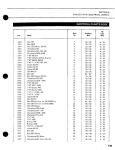
SPECIFICATIONS
--------39
---------
22
2
10 4 1
SPECIFICATIONS
440R
Valmont
440ER
Valmont
440R
Alpine
440ER
Alpine
640ER
Two
Two
Two
Two
67.5mm
61mm
436.6cc
10: 1
HD
Manual
30
67.5mm
61mm
67.5mm
61mm
436.6cc
67.5mm
61mm
436.6cc
10:1
HD
Electric
30
Two
76mm
70mm
635.1cc
9: 1
113 1/2"
35 1/2 u
40"
610
2160
.282
2 X 15"
17/38
436.6cc
10: '1
HD
10: 1
30
HD
Manual
30
103 1/2"
103 1/2"
113 1/2"
35 1/2"
40"
35 1/2"
40"
35 1/2"
40"
506
1756
.294
540
1756
.308
2160
.254
113 1/2"
35 1/2"
40"
584
2160
.270
2 X 15"
17/46
2 X 15"
2 X 15"
17/46
2 X 15"
17/46
23 Watts
75 Watts
60/60
8/23
23 Watts
75 Watts
.020"
.014"
Electric
.018"
Yes
5 gals
6.25 gals
Regular
40:1
548
17/46
35/35
8/23
Contact
.020"
.014"
No
23 Watts
75 Watts
60/60
8/23
your Sk i-Doo dealer
.020"
.018"
.014" - .018"
Yes
5 gals
6.25 gals
Regular
40:1
5 gals
6.25 gals
Regular
40:1
Alpine
HD
Electric
N/A
23 Watts
75 Watts
35/35
8/23
120 Watts
.020"
.014" - .018"
8/23
M-280-T·31
.020"
.014" .018"
No
No
5 gals
5 gals
6.25 gals
Regular
40: 1
6.25 gals
Regular
40: 1
23
1973 SKI~DOO WARRANTY
Bombardier Limited (BombardIer) as manufacturer, warrants every 1973 Ski-Doo snowmobile. Ski-Boose or CarryBoose tow sled, SOLD AS A NEW VEHiCLE, BY AN AUTHORIZED SKI-DOO DEALER, to be free from defects In
material. and workmanship under normal use and service,
for a period of ninety (90) days
to the following
coverage period:
coverage to the affected parts.
3. This warranty does not apply to any defect which results
from:
i) misuse or accident,
ii) Installation of
parts other than genuine Bombardier
parts or:
Repairs by any person other than an authorized SkiDoo snowmobile dealer;
IV) Lack of preventative maintenance;
v) Alterations or modifications other than those approved in writing by Bombardier.
1. Beginning no sooner than from the date of delivery to
the first retail buyer, for a period of ninety (90) consecu-
tive days.
2. Since snow is required for snowmobiling; all deliveries
prior to December 15th, 1972, shall be covered under this warranty from December 15th, 1972 to
March 15th, 1973.
3. All units delivered on or after January 2nd, 1973, but
prior to March 31st, 1973, shall have a warranty
carry-over into the next season, starting on December
15th, 1973, for the unused portion of the ninety (90)
day wa rra nty.
CONDITIONS
1. That ma intenance be performed, at the owner's expense, as set down in the applicable owner's manual.
Any failure which occurs as a result of
maintenance ] or improper use shall not be assumed by this
warranty.
2 Any damages to any part of the above-mentioned vehicles and their components caused through improper
use or maintenance or by any part installed which is not
a genuine Ski-Doo replacement part or not installed by
an authorized Ski-Doo dealer, voids any future warranty
24
4. Proof of ownership and warranty registration must be
submitted to the service dealer by means of the Ski-Doo
Service Card.
Guidelines for proper use and maintenance are detailed in each owner's manual.
t
SKI-DOO * SHOP MANUALS
1970-1971 Completely illustrated,
with over three hundred
full size pages, the content
includes entire sections on
Eng i ne- Ca rbu reto rChassis- SuspensionElectrics-etc. Lists step
by step procedures for Repairs-Servicing and
much much more. Covers
both 1970 and 1971 vehicles. $8.95
1972
Over two hundred pages
of up-to-date information
on Repairs and Servicing.
Completely illustrated. Everything you'll ever need
to know about servicing
your 1972 Ski-Doo snowmobile. $795
1973
Supplement edition of the
, 7 2 S hop Man u aI. I neludes the latest design
cha nq es and servi c ing
techniques for '73 vehicles. $500
Reserve your copy now! Send certified cheque or money order to:
Canada
U.S.A.
Bombardier Limited,
Bombardier East Inc.,
Technical Information Centre.
Railroad Street,
8600 Decarie Blvd.,
Lee, Massachusetts, 01238
Montreal 307, P.O.
To be completed and returned with
a money order or a certified cheque
(Postage included)
NAME
(BLOCK LETTERS)
STREET
CITY
SEND ME
STATE/PROV.
'ZIP CODE
1970-71 SHOP MANUAL $8.95
0
1972SHOPMANUAL$7.95
0
1973 SUPPLEMENT $5.00
(Available December '72)
0
-Trademark Bombardier Limited
NOTE: In the event of change of ownership, complete the notice of
transfer form below m order to qualrfy the new owner for balance of
warranty All such transfers should DA reported to an authorized SkiDoo dealer for modification of the Ski-Doo Service Card
In the event of a lost SeTVIce Card contact the oriqinet sellmg dealer
for completion of the "Request for New Service Card" form. For a
$200 handling charge. Bombardier Will mall your new personalized
Service Card to you.
Bombardier Limited,
Valcourt, Quebec, Canada.
February 1972.
NOTICE OF TRANSFER
DDDD
This warranty is expressly in lieu of all other expressed or
implied warranties of Bombardier, its distributors and the
selling dealer,including any implied warranty of merchantability or fitness for any particular purpose. Neither
Bombardier, its distributors nor the seiling dealer shall be
responsible, under any circumstances, for any loss or damage as a result of hidden defects, accidents, misuses or
other faults.
Neither the distributor, the selling dealer nor any other perSQn has been authorized to make any affirmation, representation or warranty other than those contained in this warranty and if made, such affirmation, representation or
warranty shall not be enforceable against Bombardier or
any other person.
BOMBARDIER LIMITED
FEBRUARY 2, 1972
DDDtoD
Model
Vehicle Serial No.
The ownership of this vehicle IS transferred
From
::-:-------,-- - - , - - - - - - - - - - - _ . -
Signature of registered owner
Full name
Block letters
No
Street or Village
City County
Date
Backrest
• Easily installed on Ski-Doo" snowmobiles
• Can be attached at two locations-center for
driver only rear for passenger.
• Attractive sturdy leatherette and metal
construction also available chrome coated.
• Highly recommendable for all snowmobiles
carrying more than one passenger
Speedometer
Linked directly to the drive axle Direct-reading dial
indicates the speed of the vehicle in miles per
hour (MP.H) 6 digit Odometer records the
number of miles travelled.
Snow Guard
• Prevents snow from blinding trailing
snowmobilers
• Strong thick rubber ensures long lasting
durability
• Perfectly flexible even under extreme cold.
• A must for all racing snowmobiles and an added
precaution for snowmobilers on safari.
• Applicable to all models.
All genuine Ski-Doo parts and accessories are
specificallv designed to provide you with peak
performance. Whether It'S for comfort or safety,
you know that you can depend on genuine SkiDoo parts and accessories available only at SkiDoo dealers across the country.
· .. and the Bombardier corporation is behind
them all.
'Trademark Bombardier Limited
Tachometer
The tachometer registers the Impulses of the
magneto. Direct-reading dial Indicates (in
thousands) the number of revolutions per minute
(RPM) of the engine. Vital towards maximum
performance and engine diaqnosis.
Temperature Gauge
Developed for observing changes in cylinder head
temperatures. Features; high sensitivity
quick
response
special heat compensating bi-metal
internal illumination and quick connect pickup unit Applicable to all models.
480-0056 Lith'd in Canada