1
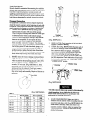
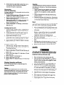
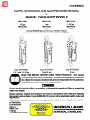
Form MHD56018
PARTS, OPERATION AND MAINTENANCE MANUAL
for
MANUAL CHAIN HOIST MODELS
M E4-005
ME4-010
ME4-015
1/2 ton
1 ton
1-1/2 ton
M E4-020
M E4-030
ME4-050
2 ton
3 ton
5 ton
Including S•COR•E (Spark and Corrosion Resistant) Features
Unless otherwise noted, tons in this manual are metric tons (2,200 Ibs.)
(Dwg. MHTPA0066)
(Dwg. MHTPA0067)
(Dwg. MHTPAO068)
1/2, 1 and 1-1/2 ton
2 and 3 ton
5 ton
READ THIS MANUAL BEFORE USING THESE PRODUCTS. This manual
contains important safety, installation, operation and maintenance information. Make this manual available to all persons responsible for the operation,
installation and maintenance of these products.
Do not use this hoist for lifting, supporting,
loads over people.
or transporting
people or lifting or supporting
Always operate, ins ect and maintain this hoist in accordance with American National
Standards Institute SafetyCode (ASME 830.16) and any other applicable safety codes and
regulations.
Refer all communications to the nearest Ingersoll-Rand Material Handling Products Office
or Distributor.
Form MHD56018
Edition 2
August 1993
71043160
© 1993 Ingersoll-Rand Company
INGERSOLL-RAND,
MATERIAL HANDLING
This manual provides important information for all
personnel involved with the safe installation, operation and
proper maintenance of this product. Even if you feel you
are familiar with this or similar equipment, you should read
and understand this manual before operating the product.
Danger, Warning, Caution and Notice
Throughout this manual there are steps and procedures
which, if not followed, may result in a injury. The following signal words are used to identify the level of potential
hazard.
Danger is used to indicate the
presence of a hazard which will
cause severe injury, death, or
substantial property damage if the
warning is ignored.
Warning is used to indicate the
presence of a hazard which can
cause severe injury, death, or
substantial property damage if the
warning is ignored.
Caution is used to indicate the
presence of a hazard which will or
can cause minor injury or property
damage if the warning is ignored.
Notice is used to notify people of
installation, operation, or maintenance information which is important but not hazard-related.
The National Safety Council, Accident Prevention Manual
for Industrial Operations, Eighth Edition and other recognized safety sources make a common point: Employees
who work near cranes or assist in hooking on or arranging
a load should be instructed to keep out from under the load.
From a safety standpoint, one factor is paramount: conduct
all lifting operations in such a manner that if there were an
equipment failure, no personnel would be injured. This
means keep out from under a raised load and keep out of
the line of force of any load.
Ingersoll-Rand Material Handling hoists are manufactured
in accordance with the latest ASME B30.16 standards.
The Occupational Safety and Health Act of 1970, generally
places the burden of compliance with the owner/employer,
not the manufacturer. Many OSHA requirements are not
concerned or connected with the manufactured product but
are, rather, connected with the final installation. It is the
owner’s responsibility and user’s responsibility to determine the suitability of a product for any particular use. It is
recommended that all applicable industry, trade association, federal, state and local regulations be checked. Read
all operating instructions and warnings before operation.
Rigging: It is the responsibility of the operator to exercise
caution, use common sense and be familiar with proper
rigging techniques. See ASME B30.9 for rigging information, American National Standards Institute, 1430 Broadway, New York, NY 10018.
Using other than genuine Ingersoll-Rand
Handling parts may void the warranty.
l
Safety Summary
Do not use this hoist for lifting, supporting, or transporting people or lifting or supporting loads over
people.
Hoists are designed to provide a 4 to 1 safety factor.
The supporting structures and load-attaching devices
used in conjunction with this hoist must provide
adequate support to handle all hoist operations plus the
weight of the hoist and attached equipment. This is the
customer’s responsibility. If in doubt, consult a
registered structural engineer.
l
l
Material
18. Never insert the point of the hook into a chain link.
19. Be certain the load is properly seated in the saddle of
the hook and the hook latch is engaged.
20. Do not support the load on the tip of the hook.
2 1. Never run the load chain over a sharp edge. Use a
sheave.
22. Pay attention to the-load at all times when operating
the hoist.
23. Always ensure that you, and all other people, are clear
of the path of the load. Do not lift a load over people.
24. Never use the hoist for lifting or lowering people, and
never allow anyone to stand on a suspended load.
25. Ease the slack out of the chain and sling when starting
a lift. Do not jerk the load.
26. Do not swing a suspended load.
27. Never leave a suspended load unattended.
28. Never weld or cut on a load suspended by the hoist.
29. Never use the hoist chains as welding electrodes.
30. Do not operate hoist if chain jumping, excessive noise,
jamming, overloading, or binding occurs.
3 1. Only operate the hoist with manual power.
32. After use, properly secure hoist and all loads.
The following warnings and operating instructions have
been adapted in part from American National (Safety)
Standard ASME B30.16 (Overhead Hoists) and are
intended to avoid unsafe operating practices which might
lead to injury or property damage.
These recommendations apply to hoists used for material
handling of freely suspended unguided loads.
Ingersoll-Rand recognizes that most companies who use
hoists have a safety program in force in their plants. In the
event you are aware that some conflict exists between a
rule set forth in this publication and a similar rule already
set by an individual company, the more stringent of the two
should take precedence.
Safe Operating Instructions are provided to make an
operator aware of dangerous practices to avoid and are not
necessarily limited to the following list. Refer to specific
sections in the manual for additional safety information.
1. Only allow people, trained in safety and operation of
this product, to operate the hoist.
2. Only operate a hoist if you are physically fit to do so.
3. When a “DO NOT OPERATE” sign is attached to the
hoist, do not operate the hoist until the sign has been
removed by designated personnel.
4. Before each shift, the operator should inspect the hoist
for wear or damage.
5. Never use a hoist which inspection indicates is worn or
damaged.
6. Periodically, inspect the hoist thoroughly and replace
worn or damaged parts.
7. Lubricate the hoist regularly.
8. Do not use hoist if hook latch on a hook has been
sprung or broken.
9. Check that the hook latches are engaged before using.
10. Never splice a hoist chain by inserting a bolt between
links.
11. Only lift loads less than or equal to the rated capacity
of the hoist. See warning tags attached to the hoist.
12. When using two hoists to suspend one load, select two
hoists each having a rated capacity equal to or more
than the load. This provides adequate safety in the
event of a sudden load shift.
13. Never place your hand inside the throat area of a hook.
14. Never use the hoist load chain as a sling.
15. Never operate a hoist when the load is not centered
under the hook. Do not “side pull” or “yard.”
16. Never operate a hoist with twisted, kinked, “capsized’
or damaged load chain.
17. Do not force a chain or hook into place by hammering.
3
Each hoist is supplied from the factory with the warning
tag shown. If the tag is not attached to your unit, order a
new tag and install it. See the parts list for the part
number. Read and obey all warnings and other safety
information attached to this hoist. Tag may not be shown
actual size.
Read the latest edition of
ASWE/ANSI 830.16. Comply with
other federal, state and local rules
Model Code Explanation
Model Code Example
Series
ME4
Hoist Capacity
005
010
015
020
030
050
=
=
=
=
=
=
l/2 metric ton (500 kg/l,100 lbs)
1 metric ton (1,000 kg/2,200 lbs)
l-1/2 metric ton (1,500 kg/3,300 lbs)
2 metric ton (2,000 kg/4,400 lbs)
3 metric ton (3,000 kg/6,600 lbs)
5 metric ton (5,000 kg/11,000 lbs)
Lift (Hoist load chain/hook travel)
10 = 10 feet (3 metres) standard
15 = 15 feet (4.5 metres)
20 = 20 feet (6 metres)
XX = Specify length
F = Hoist without chain
Hand Chain Drop (Hand chain is 2 ft. (0.6 m) less than lift)
8 = Lift 10 ft. chain drop 8 ft. (standard)
13 = Lift 15 ft. chain drop 13 ft.
18 = Lift 20 ft. chain drop 18 ft.
XX = Specify length
ME4 - 050 - 10 - 8
Table 1
No. of
chain
falls
Pull to lift rated load
Net Weight
(std. 10 ft. lift)
81
* One metric ton equals 2200 lbs.
Prior to installing the hoist, carefully inspect it for possible
shipping damage.
Hoists are supplied fully lubricated from the factory.
Lubrication of the load chain is recommended before initial
hoist operation.
Owners and users are advised to examine specific,
local or other regulations, including American
National Standards Institute and/or OSHA Regulations
which may apply to a particular type of use of this
product before installing or putting hoist to use.
Hoist Body
l
Hand Chain
A falling load can cause injury or death. Before
installing, read “SAFETY INFORMATION”.
l
(Dwg. MHTPA0490)
Hoists are designed to provide a 4 to 1 safety factor. The
supporting structures and load-attaching devices used in
conjunction with this hoist must provide adequate support
to handle all hoist operations plus the weight of the hoist
and attached equipment. This is the customer’s responsibility. If in doubt, consult a registered structural engineer.
Initial Operating Checks
Run in the hoist with a test load (10% of rated capacity) by
raising and lowering this load several times. Verify the
load brake operation with this light load prior to applying
heavier loads.
The ME4 manual chain hoist must be used in a vertical
position to provide a straight line pull from the top hook to
the bottom hook. The hoist must be positioned so that it
does not contact the support members when in use. When
operating in limited areas suitable lifting attachments or
slings must be used to prevent the hoist body and hand
chain from being obstructed.
Each time a load is lifted, the operation of the load
brake should be checked by raising the load slightly
and stopping to ensure the brake will hold the load
before proceeding to lift the load.
l
Familiarize operators and people responsible for hoist
installation and service with ASME B30.16 specifications
prior to placing the unit into service. All the requirements
of this specification, including testing should be met before
approving the hoist for operation.
5
The four most important aspects of hoist operation are:
1. Follow all safety instructions when operating the hoist.
2. Allow only people trained in safety and the operation
of this hoist to operate the hoist.
3. Subject each hoist to a regular inspection and maintenance procedure.
4. Be aware of the hoist capacity and weight of load at all
times.
The clicking sound of the pawl on the ratchet gear is
normal when a load is being raised.
l
Storing the Hoist
1. Always store the hoist in a no load condition.
2. Wipe off all dirt and water.
3. Oil the chain, hook pins and hook latch pins.
4. Hang in a dry place.
5. Before returning hoist to service follow instructions
for Hoists not in Regular Service in the “INSPECTION” section.
Only allow personnel trained in safety and operation
of this hoist to operate the hoist.
The hoist is not designed or suitable for lifting,
lowering or moving persons. Never lift loads over
people.
l
l
Hoist Operation
When facing the hand chain side of the hoist:
Rotate hand chain clockwise to raise load.
Rotate hand chain counterclockwise to lower load.
All new, altered or modified equipment should be
inspected and tested by personnel trained in safety,
operation and maintenance of this equipment to ensure
safe operation at rated specifications before placing
equipment in service.
l
Frequent and periodic inspections should be performed on
equipment in regular service. Frequent inspections are
visual examinations performed by operators or personnel
trained in safety and operation of this equipment and
include observations made during routine equipment
operation. Periodic inspections are thorough inspections
conducted by personnel trained in the safety, operation and
maintenance of this equipment. ASME B30.16 states
inspection intervals depend upon the nature of the critical
components of the equipment and the severity of usage.
Frequent and periodic inspection intervals for equipment
use under various operating conditions are listed below:
1. Frequent Inspection:
HEAVY
weekly
NORMAL
monthly
Careful inspection on a regular basis will reveal potentially
dangerous conditions while still in the early stages,
allowing corrective action to be taken before the condition
becomes dangerous.
Deficiencies revealed through inspection, or noted during
operation, must be reported to designated personnel trained
in safety, operation and maintenance of this equipment. A
determination as to whether a condition constitutes a safety
hazard must be decided, and the correction of noted safety
hazards accomplished and documented by written report
before placing the equipment in service.
Records and Reports
Inspection records, listing all points requiring periodic
inspection should be maintained for all load bearing
equipment. Written reports, based on severity of service,
should be made on the condition of critical parts as a
method of documenting periodic inspections. These
reports should be dated, signed by the person who performed the inspection, and kept on file where they are
readily available for review.
SEVERE
daily
The external placement of coded marks on equipment
identifying completed inspections and operationally
certified equipment is an acceptable method of documenting periodic inspections in place of written
records.
l
2.
Periodic Inspection:
NORMAL
yearly
HEAVY
semi-annually
SEVERE
quarterly
Load Chain Reports
Records should be maintained documenting the condition
of load chain removed from service as part of a long-range
load chain inspection program. Accurate records will
establish a relationship between visual observations noted
during frequent inspections and the actual condition of the
load chain as determined by periodic inspection methods.
Frequent Inspection
On equipment in continuous service, frequent inspection
should be made by operators at the beginning of each shift.
In addition, visual inspections should be conducted during
regular operation for damage or evidence of malfunction.
1. OPERATION. Operate the hoist by raising a load
approximately 6 inches (150 mm) off the ground.
While lifting and lowering load, check for visual signs
or abnormal noises which could indicate damage.
Check for smooth operation; binding or any malfunctions are not acceptable. Do not operate the hoist
unless the chain feeds through the hoist and hook
block smoothly. Listen for “clicking”. The clicking
sound of the paw1 on the ratchet gear is normal when a
load is being raised. If load chain binds, jumps, or is
excessively noisy, clean and lubricate the chain. If
problem persists, replace the load chain. Hand chain
should move freely; without binding or excessive drag.
Hook should stop moving when hand chain stops
moving.
2. HOOKS. Check for wear or damage, increased throat
width, bent shank or twisting of hook. Replace hooks
which exceed the throad opening discard width (15%)
shown in Table 2 (ref. Dwg. MHTPA0040) or that
exceed a 10” twist (ref. Dwg. MHTPA0l11). If the
hook latch snaps past the tip of the hook, the hook is
sprung and must be replaced. Check hook support
bearings for lubrication and damage. Make sure that
they swivel easily and smoothly. Repair or lubricate as
necessary.
Twisted
DO NOT USE
Normal
Can Be Used
(Dwg. MHTPA0111)
3.
4.
HOOK LATCH. Check operation of the hook latch.
Replace if broken or missing.
CHAIN. (Ref. Dwg. MHTPA0102) Examine each of
the links for bending, cracks in weld areas or shoulders, transverse nicks and gouges, weld splatter,
corrosion pits, striation (minute parallel lines) and
chain wear, including the load bearing surfaces
between chain links. Replace the entire chain if any
part fails inspection. Check lubrication of load chain
and lubricate if necessary. See “Load Chain” in the
“LUBRICATION”
section.
Diameter
Welded Area
Wear in
these areas
Throat Width
(Dwg. MHTPA0102)
The full extent of chain wear cannot be determined by
visual inspection. At any indication of chain wear
inspect chain and load sheave in accordance with
instructions in “Periodic Inspection.
l
(Dwg. MHTPA0040)
Table 2
5.
7
LOAD CHAIN REEVING. Make sure chain is
installed correctly and the welds on standing links are
away from load sheave (ref. Dwg. MHTPAO042). Reinstall chain if necessary. Make sure chain is not
capsized, twisted or kinked. Adjust as required. See
“MAINTENANCE”
section for load chain reeving
detailed information.
Periodic Inspection
Table 3
Model
No.
Refer to “INSPECTION AND MAINTENANCE
REPORT” for guidance on documenting periodic
inspection items.
Part NO.
Chain
Size
Normal
Length
Discard
Length
l
Disassembly may be required as a result of initial indications of inspections or in order to properly inspect the
individual components. Disassembly steps are described in
the “MAINTENANCE”
section. Maintain written records
of periodic inspections to provide an accumulative basis for
continuing evaluation. Inspect all items listed in “Frequent
Inspection.” Also inspect the following:
1. FASTENERS. Check retainer rings, split pins,
capscrews, nuts, and other fasteners on hooks, hoist
body and trolley (as applicable). Replace if missing or
damaged and tighten if loose.
2. ALL COMPONENTS. Inspect for wear, damage,
distortion, deformation and cleanliness. If external
evidence indicates potential damage, disassemble as
required to conduct a detailed inspection. Inspect
gears, shafts, bearings, sheaves, chain guides, springs
and covers. Replace worn or damaged parts. Clean,
lubricate and reassemble.
3. HOOKS. Inspect hooks for cracks. Use magnetic
particle or dye penetrant methods to check for cracks.
Inspect hook retaining parts. Tighten, repair or replace,
if necessary. Refer to ASME B30.10 (HOOKS) for
additional hook inspection information.
4. CHAIN SHEAVES. Check for damage or excessive
wear. Replace damaged parts.
5. BRAKES. Ensure proper operation. Brake should not
slip with test load (10% of capacity). If initial inspection indicates the need, disassemble. Brake discs must
be free of excess oil or grease, must appear unglazed,
must be uniform in thickness and be at least 3/32 inch
(2.5 mm) thick. Check all other brake surfaces for
wear, deformation or foreign deposits. Check paw1
brake. Teeth of ratchet gear should be undamaged, and
should stop gear rotation in the counterclockwise
direction. Check paw1 spring for damage. Clean and
replace components as necessary.
6. TAIL PIN. (End Anchor) Ensure end tail pin on chain
hoist is engaged and unbent. Replace if damaged or
missing. Refer to “Attaching End of Load Chain” in
the “MAINTENANCE”
section to remove, install or
replace.
7. LOAD CHAIN. Inspect chain for stretching by
measuring across five link sections throughout the
length of the chain (ref. Dwg. MHTPA0041). If any
five lengths in the working length reaches or exceeds
the discard length, replace the entire chain. Discard
lengths are shown in Table 3 . Always use a genuine
Ingersoll-Rand Material Handling replacement
chain.
ME4-005
ME4-010
ME4-015
ME4-020
ME4-030
ME4-050
Gauge Length
(Dwg. MHTPA0041)
8.
9.
SUPPORTING STRUCTURE. Check for distortion,
wear and continued ability to support load.
LABELS. Check for presence and legibility of labels.
Replace if damaged or missing.
Equipment Not in Regular Use
1. Equipment which has been idle for a period of one
month or more, but less than one year, shall be given
an inspection conforming to the requirements of
“Frequent Inspection” before being placed in service
for general use.
2. Equipment which has been idle for a period of over
one year shall be given a complete inspection conforming with the requirements of “Periodic Inspection” before being place in service for general use.
3. Standby equipment shall be inspected at least semiannually in accordance with the requirements of
“Frequent Inspection”. In abnormal operating conditions equipment should be inspected at shorter
intervals.
INSPECTION
AND MAINTENANCE
REPORT
ME4 Model Hoists
Model Number:
Date:
Serial Number:
Inspected by:
Reason for Inspection: (Check Applicable Box)
1. Scheduled Periodic Inspeciton ( _
Monthly
_
Quarterly
_
Yearly).
2. Descrepancy(s) noted during Frequent Inspection.
3. Descrepancy(s) noted during maintenance.
4. Other:
Refer to the Parts, Operation and Maintenance Manual “INSPECTION” section for general inspection criteria. Refer to applicable component and unit
American National Standards Institute Safety Codes for specific technical requirements. If in doubt about an existing condition contact the nearest
INGERSOLL-RAND Distributor or the factory for technical assistance.
NOTES
F
Actual Hook Throat Width:
Top
inches /
Hook Twist
Hook Crack Test Method Used . -
Dye Penetrant -
Actual Hook Throat Width:
Bottom
mm (reference Table 2 for maximum acceptable width).
___
HookTwist
(maximum 10%)
inches /
Hook Latch
Brakes
10% Load Test)
Other:
mm (reference Table 2 for maximum acceptable width).
(maximum 10%)
I
Hook Crack Test Method Used: -
Magnetic Particle -
Dye Penetrant ___
Magnetic Particle __
Other:
___
Brakes
Visual Inspection)
rail Pin (End Anchor)
Load Chain
--inches /
Working length(s) maximum stretch:
mm (reference Table 3 for maximum acceptable stretching).
Supporting Structure
LabeIs and Tags
Other Components
list in NOTES section)
Testing:
Pass
Fail
Operational (No Load)
Operational (10% Load)
Operational (Maximum Test Load *)
*
Refer to the Parts, Operation and Maintenance manual “Testing” in the “MAINTENANCE”
9
section to determine Maximum Test Load,
Load Chain
General
Thread lubricant or an anti-seize compound use is recommended for threaded shafts, capscrews and nuts. Unless
otherwise stated, remove old lubricant, clean the part with
an acid free solvent and apply a new coating of lubricant to
the part before assembly.
Failure to maintain clean and well lubricated load
chain may result in chain failure causing injury, death
or substantial property damage.
l
Gears (19)
Unscrew U-nuts (23), on the opposite side of the hoist as
the hand chain, and remove body (11). Remove old grease
and replace with new. See “Accessing Load Gear (19)” in
“MAINTENANCE”
section. For temperatures -20” to 50” F
(-29” to 10” C) use EP 1 grease or equivalent. For temperatures 30” to 120” F (-1” to 49” C) use EP 2 grease or
equivalent.
1. Lubricate load chain weekly, or more frequently,
depending on severity of service.
2. In a corrosive environment, lubricate more frequently
than normal.
3. Lubricate each link of the chain and apply new
lubricant over existing layer.
4. Lubricate hook and hook latch pivot points.
5. Clean chain with acid free solvent to remove rust or
abrasive dust build-up and lubricate the chain.
6. Use Ingersoll-Rand Lubri-Link® or a SAE 50 to 90
EP oil.
This section provides basic troubleshooting information. Determination of specific causes to problems are best identified by
thorough inspections performed by personnel trained in safety, operation and maintenance of this equipment. The chart below
provides a brief guide to common hoist problems, probable causes and solutions.
PROBLEM
SOLUTION
CAUSE
Hoist will not hold
rated load.
Brake may be slipping.
Inspect and repair as described in the “INSPECTION”
“MAINTENANCE”
sections.
Hoist will not lift
load.
Hoist is overloaded.
Reduce load to within rated capacity.
Load Chain Binds.
Damaged load chain, pinion
shaft, gears or sheaves.
Disassemble and inspect components as described in the
“MAINTENANCE”
and “INSPECTION” sections.
Load chain not installed
properly (twisted, kinked or
“capsized”).
Inspect and repair as described in the “INSPECTION”
“MAINTENANCE”
sections.
Hand Chain Binds.
Load Hook Latch
does not work.
and
and
/
Damaged hand chain or hand Disassemble and inspect components as described in the
wheel.
“MAINTENANCE”
and “INSPECTION” sections.
Hand chain not installed
properly (twisted).
Untwist hand chain. Refer to “MAINTENANCE”
additional information.
Latch broken.
Replace hook latch.
Load hook bent or twisted.
Inspect load hook as described in “INSPECTION”
necessary.
10
section for
section. Replace if
Attaching End of Load Chain
1. Remove socket bolt (41) and remove tail pin (40).
2. Make sure load chain (42) is not twisted, kinked or
“capsized.” (ref. Dwg. MHTPA0020)
3. Position end link of load chain (42) between body A
(10) and body B (11) and slide tail pin (40) through
end link. Secure by installing socket bolt (41).
Never perform maintenance on the hoist while it is
supporting a load.
Before performing maintenance, tag hoist:
DANGER - DO NOT OPERATE EQUIPMENT BEING REPAIRED.
Only allow personnel trained in operating and
servicing this product to perform maintenance.
After performing maintenance on the hoist, test unit
to 125% of its rated capacity before returning to
service. Testing to 150% of rated capacity might be
required to comply with standards and regulations set
forth in areas outside of the USA.
l
l
l
l
Installing New Load Chain
Do not remove the old load chain from the hoist. The
old load chain can be used to install the new load chain.
l
Appearance of
chain that is
Not Twisted
Appearance of
chain that
Is Twisted
(Dwg. MHTPA0020)
To prevent a falling load which can cause death,
injury or property damage the hook (4) must be on
right fall of load chain (42) and left fall must be attached to hoist body with tail pin (40). Right and left
are designated when viewed from the hand chain side of
the hoist.
l
General Disassembly
The following instructions provide the necessary information to disassemble, inspect, repair, and assemble the hoist.
Parts drawings of the hoist assembly are provided in the
Parts Section.
If a hoist is being completely disassembled for any reason,
follow the order of the topics as they are presented.
It is recommended that all maintenance work on the hoist
be performed on a bench.
In the process of disassembling the hoist, observe the
following:
1. Never disassemble the hoist any further than is
necessary to accomplish the needed repair. A good
part can be damaged during the course of disassembly.
2. Never use excessive force when removing parts.
Tapping gently around the perimeter of a cover or
housing with a soft hammer, for example, is sufficient
to break the seal.
3. Do not heat a part with a flame to free it for removal.
In general, the hoist is designed to permit easy
disassembly and assembly. The use of heat or excessive force should not be required.
4. Keep the work area as clean as practical, to prevent
dirt and other foreign matter from getting into bearings
or other moving parts.
5. When grasping a part in a vise, always use leathercovered or copper-covered vise jaws to protect the
surface of the part and help prevent distortion. This is
particularly true of threaded members and housings.
1. Ensure welds of “standing” links on the new chain are
facing away from the load sheave (18). (ref. Dwg.
MHTPA0042)
2. Ensure load chain (42) is reeved between load sheave
(18) and chain guides (20 and 20A).
3. Hook (4) must be on right fall of load chain (42) and
left fall must be attached to hoist body with tail pin
(40). Right and left are designated when viewed from
the hand chain side of the hoist.
Load Chain
Load Sheave
Standing Link
(Dwg. MHTPA0042)
11
6.
Do not remove any part which is press fit in or on a
sub-assembly unless the removal of that part is
necessary for repairs or replacement.
Inspection
All disassembled parts should be inspected to determine
their fitness for continued use. Pay particular attention to
the following:
1. Inspect all gears for worn, cracked, or broken teeth.
2. Inspect shafts for ridges caused by wear. If ridges
caused by wear are apparent on shafts, replace the
shaft.
3. Inspect all threaded items and replace those having
damaged threads.
4. Measure the thickness of the brake discs. If brake discs
do not have uniform thickness or are less than 3/32 in.
(2.4 mm) thick replace brake discs.
Disassembly
Brake Disc Replacement
To remove brake discs (32), disassemble the hoist with the
following procedure:
1. Unscrew Phillips head screws (38) and remove spring
washers (39). Remove wheel cover (37).
2. Remove split pin (36) and pull out stopper pin (35).
Remove wheel stopper (34).
3. Remove hand wheel (33) by holding load chain (42)
and rotating hand wheel (33) counterclockwise.
Remove one brake disc (32).
4. Remove ratchet gear (31) bushing (30) and second
brake disc (32).
Repair
Actual repairs are limited to the removal of small burrs and
other minor surface imperfections from gears and shafts.
Use a fine stone or emery cloth for this work.
1. Worn or damaged parts must be replaced. Refer to the
applicable parts listing for specific replacement parts
information.
2. Inspect all remaining parts for evidence of damage.
Replace or repair any part which is in questionable
condition. The cost of the part is often minor in
comparison with the cost of redoing the job.
3. Smooth out all nicks, burrs, or galled spots on shafts,
bores, pins, and bushings.
4. Examine all gear teeth carefully, and remove nicks and
burrs.
5. Polish the edges of all shaft shoulders to remove small
nicks which may have been caused during handling.
6. Remove all nicks and burrs caused by lockwashers.
Accessing Load Gear (19)
1. Follow the steps 1 through 4 under “Disassembly for
Brake Disc Replacement” to access socket bolts (22
and 22A).
2. Loosen socket bolts (22 and 22A) until U-nuts (23)
come off. Remove socket bolts (22 and 22A).
3. Position hoist with body B (11) up.
4. While using cutouts in body B (11) to hold frame (13)
against body A (10), carefully pry body B (11) apart
from frame (13). Remove body B (11).
5. Inspect load gear (19). Repair or replace if necessary.
Lubricate as needed.
Accessing Load Sheave (18)
1. Follow the steps 1 through 4 under “Disassembly for
Brake Disc Replacement” and steps 1 through 5 under
“Accessing Load Gear.”
2. Unscrew friction disc (29) from pinion (14).
3. Remove socket bolts (22) and (22A) then lift body off
body A (10).
4. Remove load chain stripper (21), load sheave (18) and
chain guide (20).
5. Remove top pin (3) and top hook (1).
6. Remove load chain tail pin (40).
7. Remove frame (13). Separate load gear (19) from body
B (11).
Assembly
Brake Discs
The brake will not operate properly if there is oil on
the brake discs (32). Excessive oil or grease on brake
components could cause the load to slip.
l
1. Place one brake disc (32) on friction disc (29).
2. Install bushing (30) and ratchet gear (3 1). Paw1 (27)
and ratchet gear (3 1) must “click” when gear (3 1) is
rotated clockwise and must also stop gear (3 1) from
rotating counterclockwise.
3. Place the other brake disc (32) on ratchet gear (3 1).
4. Ensure hand chain (43) is properly seated in hand
wheel (33). With brake surface towards brake disc
(32), place hand wheel (33) on pinion (14). Rotate
hand wheel (33) clockwise until clicking occurs. Hold
load chain (42) to keep pinion (14) from rotating, if
necessary.
5. Align pilot holes in wheel stopper (34) and pinion
(14).
6. Insert stopper pin (35) through wheel stopper (34).
Install split pin (36) and spread prongs apart.
7. Position wheel cover (37) and secure with spring
washers (39) and screws (38).
Cleaning, Inspection and Repair
Use the following procedures to clean and inspect the
components of the hoist.
Cleaning
Clean all hoist component parts in an acid free solvent
(except for the brake discs). The use of a stiff bristle brush
will facilitate the removal of accumulated dirt and sediments on the gears and frames. Dry each part using low
pressure, filtered compressed air.
17
Load Gear (19) Assembly
1. Lubricate and install load gear (19).
2. Making sure chain stripper (21) is seated in frame
(13), position body B (11) on frame (13).
3. Place U-nuts (23) into indentions in body B (11).
Insert and tighten socket bolts (22 and 22A).
4. Lay hoist on body B (11) and make sure friction disc (29)
is seated. Rotate friction disc (29) clockwise if necessary*
5. Follow steps 1 through 7 under “Assembly of Brake
Discs” to complete assembly of hoist.
Load Sheave (18) Assembly
1. Apply a generous amount of grease to load gear (19)
and install in body B (11).
2. Install frame (13).
3. Install load sheave (18) and load chain. Install load
chain stripper (21) and chain guide (20).
4. Install load chain tail pin (40) and last link of load
chain. Ensure load chain is not twisted.
5. Install top hook (1) with top pin (3).
6. Install pinion (14) so splined end enters first.
7. Install body A (10) and secure with socket bolts (22)
and (22A).
8. Install friction disc (29) by screwing it onto pinion
(14) until snug.
9. Follow steps 1 through 5 under “Load Gear Assembly”
and 1 through 7 under “Assembly of Brake Discs” to
complete assembly of hoist.
Vise(Dwg. MHTPA0014)
2. If you are replacing the hand chain, disconnect it at
the “C” link and carefully remove the hand chain.
3. When replacing a hand chain, cut a length 2 times the
required hand chain drop plus about one foot (305
mm). For adjustments, remove or add a length of
chain twice the difference in hand chain
height. To prevent the hand chain from twisting,
maintain an even number of links, by removing or
adding an even number of links.
4. If you are replacing the hand chain, run the new hand
chain up through the left hand chain guide, around
the handwheel, making sure the hand chain is seated
in the handwheel pockets, and back down through
the right hand chain guide.
5. Connect the hand chain ends with the “C” link(s),
making the total number of links even, and bend the
“C” link(s) shut.
6. Make sure the hand chain is not twisted. If twisted,
untwist or open a “C” link and remove one hand
chain link if necessary.
Hand Chain Adjustment or Replacement
When cutting the weld side of a hand chain link, do
not cut or nick the opposite side. A damaged link must
be replaced to prevent premature failure. A falling
hand chain could cause injury.
l
“C” Link
Load Test
Prior to initial use, all new, extensively repaired, or altered
hoists shall be load tested by or under the direction of a
person trained in the operation and maintenance of this
hoist, and a written report furnished confirming the rating
of the hoist. Test hoist to 125% of its rated capacity.
Testing to 150% of the rated hoist capacity may be
necessary to comply with standards and regulations set
forth in areas outside of the USA.
(Dwg. MHTPA0016)
1. To create a “C” link, cut the welded side of the link with
a hack saw. Clamp one side of the “C” link in a vise
and bend it open by using a pliers to grip the exposed
part of the link. Refer to Dwgs. MHTPA0014 and
MHTPA0016.
13
Model:
ME
ME4
As part of our continuing effort to provide the best available products, the ME underwent a minor redesign. Several
internal parts were changed. The improved version of the
ME was renamed the ME4. From the outside, the ME4
and ME look alike. To determine which model you have,
look at the model label attached to the unit.
Usage:
Soak the brake discs in oil
Use the asbestos-free brake discs dry.
The parts that have been changed are listed below. None
of the parts listed below are interchangeable between the
ME4 and the ME. All other parts are interchangeable.
From the standpoint of maintaining the hoist, the most
important change is the treatment of the brake discs. The
ME brake discs must be soaked in oil. See the ME
Operation and Maintenance manual for duration and oil
type. The asbestos-free ME4 brake discs must be used dry.
COMMENTS:
Brake Disc (ME4)
14
Return Goods Policy
Ingersoll-Rand will not accept any returned goods for
warranty or service work unless prior arrangements have
been made and written authorization has been provided
from the location where the goods were purchased.
Hoists returned with opened, bent or twisted hooks, or
without chain and hooks, will not be repaired or replaced
under warranty.
The use of replacement parts other than genuine
Ingersoll-Rand Material Handling parts may invalidate
the Company’s warranty. For prompt service and genuine
Ingersoll-Rand Material Handling parts provide your
nearest Distributor with the following:
1. Complete model number as it appears on the name
plate: ME4 plus capacity.
2. Part number and part name as shown in manual.
3. Quantity required.
The hoist nameplate is located on the gear cover. Example
shown is for a 3 ton ME4 hoist. Nameplate is not shown
actual size.
Continuing improvement and advancement of design
may cause changes to this hoist which are not included
in this manual. Manuals are periodically revised to
incorporate changes. Always check the manual edition
number on the front cover for the latest issue.
If your hoist has special finish requirements for
painted parts, please specify when ordering.
l
l
When the life of the hoist has expired, it is recommended
that the hoist be disassembled, degreased and parts
separated as to materials so that they may be recycled.
For additional information contact:
Manual Chain Hoist
Ingersoll-Rand Material Handling
2724 Sixth Avenue South
Seattle, Wa 98124 USA
Phone: (206) 624-0466
Fax: (206) 624-6265
or
Ingersoll-Rand Material Handling
Samiia, Douai Operations
111, avenue Roger Salengro
59450 Sin Le Noble, France
Phone: (33) 27-93-08-08
Fax: (33) 27-93-08-00
For your convenience and future reference it is recommended that the following information be recorded.
Hoist Model Number ..........................................................
Hoist Serial Number ...........................................................
Date Purchased ....................................................................
Description
Orange Touch-Up Paint
Chain Lubricant
Chain Lubricant (Food Grade)
Part No.
MHD-OR
LUBRI-LINK
LUBRI-LINK
GREEN
15
.
2 and 3 ton Top and Bottom Hooks
5 ton Top and Bottom Hooks
(Dwg. MHTPB0069)
ITEM
NO.
1
2
I
DESCRIPTION
OF PART
PART NO.
QTY
Top Hook Assembly
Hook Latch T
1
1
24
25
26
27
28
29
30
31
Paw1 Pin
U-Nut
Paw1 Spring
Paw1 - Snap Ring
Friction Disc
Bushing
Ratchet Gear
1
1
1
1
1
1
1
1
33
34
35
36
37
38
39
Hand Wheel
Wheel Stopper 1
Wheel Stopper Pin
Split Pin
Wheel Cover
Screw
Spring Washer
1
1
1
1
1
3
3
40
41
42
Tail Pin
Socket Bolt
Load Chain
1
1
1
1 ton
71307
71306
71255
71256
71627
71628
2 ton
3 ton
___
- __
___
___
- __
___
5 ton
I
13
--I_
/
71236
71239
71234
71233
71232
71941
71944
7 1036446
72053
73Mh
,--I-
71036495 1 71036503 1 71036495
71654
71225
71224
71223 1 71655 1 71656 ( 71655
71222
71221
71657 1 71658 1 71657
71220
71659
71219
LCCF005
LCCF010 1 LCCF015 [ LCCF010
1 71036487
1 71226
Recommended spares.
17
1
7 1036503
1
71656
1
71658
1
LCCF015
I
*
77
78
79
80
8l
Warning Tag
Tag Ring
Chain Installation Label
Brake Disc Label
Parts, Operation and
Maintenance Manual
*
Recommended spares
Not illustrated
1
1
1
1
71038863
50040
T-6
71043871
1
Form No. MHD560 18
18
HOIST AND WINCH LIMITED WARRANTY
Ingersoll-Rand Company (I-R) warrants to the
original user its Hoists and Winches (Products)
to be free of defects in material and workmanship for a period of one year from the date of
purchase. I-R will repair, without cost, any
Product found to be defective, including parts
and labor charges, or at its option, will replace
such Products or refund the purchase price less a
reasonable allowance for depreciation, in
exchange for the Product. Repairs or replacements are warranted for the remainder of the
original warranty period.
I-R makes no other warranty, and all implied
warranties including any warranty of
merchantability or fitness for a particular
purpose are limited to the duration of the
expressed warranty period as set forth above.
I-R’s maximum liability is limited to the
purchase price of the Product and in no event
shall I-R be liable for any consequential,
indirect, incidental, or special damages of any
nature rising from the sale or use of the Product, whether based on contract, tort, or otherwise.
If any Product proves defective within its
original one year warranty period, it, should be
returned to any Authorized Hoist and Winch
Service Distributor, transportation prepaid with
proof of purchase or warranty card.
Note: Some states do not allow limitations on
incidental or consequential damages or how long
an implied warranty lasts so that the above
limitations may not apply to you.
This warranty gives you specific legal rights and
you may also have other rights which may vary
from state to state.
This warranty does not apply to Products which
I-R has determined to have been misused or
abused, improperly maintained by the user, or
where the malfunction or defect can be attributed
to the use of non-genuine I-R parts.
IMPORTANT NOTICE
apparent good condition, but upon opening the
crate or container, loss or damage has taken place
while in transit, notify the carrier’s agent immediately.
It is our policy to promote safe delivery of all
orders.
This shipment has been thoroughly checked,
packed and inspected before leaving our plant
and receipt for it in good condition has been
received from the carrier. Any loss or damage
which occurs to this shipment while enroute is
not due to any action or conduct of the manufacturer.
VISIBLE
DAMAGE
LOSS OR DAMAGE
If any of the goods called for on the bill of lading
or express receipt are damaged or the quantity is
short, do not accept them until the freight or
express agent makes an appropriate notation on
your freight bill or express receipt.
CONCEALED
CLAIMS
You must file claims for damage with the carrier.
It is the transportation company’s responsibility to
reimburse you for repair or replacement of goods
damaged in shipment. Claims for loss or damage in
shipment must not be deducted from the
Ingersoll-Rand invoice, nor should payment of
Ingersoll-Rand invoice be withheld awaiting
adjustment of such claims as the carrier guarantees
safe delivery.
You may return products damaged in shipment to
us for repair, which services will be for your
account and form your basis for claim against the
carrier.
LOSS OR DAMAGE
When a shipment has been delivered to you in
19
For Order Entry and
Order Status
Ingersoll-Rand
Distribution Center
P.O. Box 618
5 10 Hester Drive
White House, TN 37188
Phone: (615) 672-0321
Telex: 786573
Fax:
(615) 672-0801
Regional Sales Offices
Atlanta, GA
111 Ingersoll-Rand Drive
Chamblee, GA 3034 1
Phone: (404) 936-6230
Detroit, MI
23 192 Commerce Drive
Farmington Hills, MI 48335
Phone: (3 13) 476-6677
(3 13) 476-6670
Fax:
For Technical Support
Ingersoll-Rand
Material Handling
P.O. Box 24046
2724 Sixth Avenue South
Seattle, WA 98 124-0046
Phone: (206) 624-0466
Telex: 328795
(206) 624-6265
Fax:
Houston, TX
Suite 150
2500 East T.C. Jester
Houston, TX 77008
Phone: (7 13) 864-3700
Los Angeles, CA
5533 East Olympic Blvd.
Los Angeles, CA 90022
Phone: (213) 725-2826
Milwaukee, WI
12311 W. Silver Spring Dr.
Milwaukee, WI 53225
Phone: (414) 461-0973
Philadelphia, PA
P.O. Box 425
900 E. 8th Ave., Suite 103
King of Prussia, PA 19406
Phone: (215) 337-5930
Offices and distributors in
principal cities throughout
the world. Contact the
nearest Ingersoll-Rand
office for the name and
address of the distributor
in your country or write/
fax to:
Ingersoll-Rand
Material Handling
P.O. Box 24046
2724 Sixth Avenue South
Seattle, WA 98 124-0046
USA
Phone: (206) 624-0466
Telex: 328795
Fax:
(206) 624-6265
Canada
National Sales Office
Regional Warehouse
Toronto, Ontario
5 1 Worcester Road
Rexdale, Ontario
M9W 4K2
Phone: (416) 675-5611
Fax:
(416) 675-6920
Order Desk
Fax:
(4 16) 674-6549
Regional Sales Offices
Calgary, Alberta
44 Harley Road S.E.
Calgary, Alberta
T2V 3K3
Phone: (403) 252-4 180
Fax:
(403) 252-4462
Edmonton, Alberta
1430 Weber Center
5555 Calgary Trail N.W.
Edmonton, Alberta
T6H 5G8
Phone: (403) 438-5039
Fax:
(403) 437-3 145
Montreal, Quebec
3501 St. Charles Blvd.
Kirkland, Quebec
H9H 4S3
Phone: (5 14) 695-9040
Fax:
(514) 695-0963
Printed in USA
British Columbia
201-635 1 Westminster Hwy
Richmond, B. C.
v7c 5c7
Phone: (604) 278-0459
Fax:
(604) 278-25 19
Latin America Operations
Ingersoll-Rand
Production Equipment
Group
730 N.W. 107 Avenue
Suite 300, Miami, FL
33 172-3 107
Phone: (305) 559-0500
Telex: 441617TLS UI
Fax:
(305) 559-7505
Europe, Middle East and
Africa
Ingersoll-Rand
Material Handling
Samiia, Douai Operations
111, avenue Roger Salengro
59450 Sin Le Noble, France
Phone: (33) 27-93-08-08
Fax:
(33) 27-93-08-00
Asia Pacific Operations
Ingersoll-Rand (Japan) Ltd.
Kawa Bldg. No. 17
2-7 Nishi-Azabu 1-Chrome
Minato-ku, Tokyo 106 Japan
Phone: (03) 3403-0641/7
Fax:
813 3401-2409
Russia
Ingersoll-Rand Company
World Trade Center
Office 1101
Krasnopresnenskaya Nab. 12
Moscow, Russia 123610