1
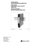
User´s Manual Model RAKD Small Metal ROTAMETER IM 01R01B30-00E-E Rota Yokogawa GmbH & Co. KG Rheinstr. 8 D-79664 Wehr Germany IM 01R01B30-00E-E 4th edition, April 2007 Blank Page CONTENTS Contents 1. Introduction ......................................................................................... 1-1 1.1 Template ........................................................................................................1-3 1.2 ATEX Documentation ...................................................................................1-6 1.3 General description ......................................................................................1-8 1.4 Principle of measurement ............................................................................1-8 1.5 Overview ........................................................................................................1-9 2. Precautions .......................................................................................... 2-1 2.1 Transportation and Storage .........................................................................2-1 2.2 Installation .....................................................................................................2-1 3. Installation ........................................................................................... 3-1 3.1 Installation in the pipeline ............................................................................3-1 3.2 Wiring .............................................................................................................3-1 3.2.1 Connecting diagrams ....................................................................................... 3-1 3.2.2 Conductor connection (Quickon) .................................................................... 3-4 4. Start of operation ................................................................................ 4-1 4.1 Hints on flow rate measurement .................................................................4-1 4.2 Pulsation and pressure shock .....................................................................4-1 4.3 Start of operation of electronic transmitter ................................................4-1 5. Limit switches (Option /K1 to /K8) ..................................................... 5-1 6. Maintenance......................................................................................... 6-1 6.1 Function test .................................................................................................6-1 6.2 Measuring tube, float ....................................................................................6-1 6.3 Explosion drawings ......................................................................................6-2 6.4 Electronic transmitter ...................................................................................6-3 6.5 Exchange of scale ........................................................................................6-3 6.6 Exchange of indicator ..................................................................................6-3 6.7 Troubleshooting............................................................................................6-4 7. Technical Data ..................................................................................... 7-1 7.1 RAKD Type-, Suffix-codes and Options......................................................7-1 7.2 Specifications ...............................................................................................7-6 7.3 Dimensions and weights ..............................................................................7-9 7.4 Temperatue curves .....................................................................................7-13 All Rights Reserved, Copyright 2003. Rota Yokogawa GmbH & Co. KG i IM 01R01B30-00E-E 4th edition, April 2007 CONTENTS 8. Explosion-protected Type Instruments ............................................. 8-1 8.1 General .........................................................................................................8-1 8.2 Intrinsically safe ATEX certified RAKD (/KS1) ...........................................8-2 8.2.1 Technical data ................................................................................................... 8-2 8.2.2 Installation ......................................................................................................... 8-4 8.3 Non incendive RAKD for Category 3 (ATEX) (/KN1) ..................................8-5 8.4 Dust proofed limt switches (ATEX) (/KS2) ..................................................8-6 8.5 Intrinsically safe SAA (Australia) certified limit switches (/SS1) .............8-6 8.6 Intrinsically safe CSA (USA + Canada) limit switches (/CS1) ...................8-6 8.7 Intrinsically safe NEPSI (China) certified RAKD (/NS1) .............................8-9 IM 01R01B30-00E-E 4th edition, April 2007 ii 1. INTRODUCTION 1. Introduction Before use, read this manual thoroughly and familiarize yourself fully with the features, operations and handling of Rotameter RAKD to have the instrument deliver its full capabilities and to ensure its efficient and correct use. The following safety symbols and cautionary notes are used on the product and in this manual: WARNING This symbol is used to indicate that a hazardous condition will result which, if not avoided, may lead to loss of life or serious injury. This manual describes how the operator should exercise care to avoid such a risk.. Notices Regarding This Manual • This manual should be passed to the end user. • The contents of this manual are subject to change without prior notice. • All rights reserved. No part of this document may be reproduced or transmitted in any form or by any means without the written permission of Rota Yokogawa (hereinafter simply referred to as Yokogawa). • This manual neither does warrant the marketability of this instrument nor it does warrant that the instrument will suit a particular purpose of the user. • Every effort has been made to ensure accuracy in the contents of this manual. However, should any questions arise or errors come to your attention, please contact your nearest Yokogawa sales office that appears on the back of this manual or the sales representative from which you purchased the product. • This manual is not intended for models with custom specifications. • Revisions may not always be made in this manual in conjunction with changes in specifications, constructions and/or components if such changes are not deemed to interfere with the instrument’s functionality or perfor-mance. CAUTION This symbol is used to indicate that a hazardous condition will result which, if not avoided, may lead to minor injury or material damage. This manual describes how the operator should exercise care to avoid a risk of bodily injury or damage to the instrument. IMPORTANT This symbol is used to call your attention to a condition that must be observed in order to avoid the risk of damage to the instrument or system problems. NOTE This symbol is used to call your attention to information that should be referred to in order to know the operations and functions of the instrument. Notices Regarding Safety and Modification • For the protection and safety of personnel, the instrument and the system comprising the instrument, be sure to follow the instructions on safety described in this manual when handling the product. If you handle the instrumentin a manner contrary to these instructions, Yokogawa does not guarantee safety. • If this instrument is used in a manner not specified in this manual, the protection provided by this instrument may be impaired. • As for explosionproof model, if you yourself repair or modify the instrument and then fail to return it to its original form, the explosionprotected construction of the instrument will be impaired, creating a hazardous condition. Be sure to consult Yokogawa for repairs and modifications. For Safe Use of Rotameter RAMC WARNING • If the process fluid is harmful to personnel, handle Rotameter RAKD carefully even after it has been removed from the process line for maintenance or other purposes. Exercise extreme care to prevent the fluid from coming into contact with human flesh and to avoid inhaling any residual gas. • In case of Explosion proof type instrument, further requirements and differences are described in Chapter 8 " INSTRUCTIONS FOR EXPLOSION PROTECTED RAKD”. The description in Chapter 8 is prior to other descriptions in this instruction manual. 1-1 IM 01R01B30-00E-E 4th edition, April 2007 1. INTRODUCTION CAUTION WARNING • When carrying Rotameter RAKD around, exercise extreme care to avoid dropping it accidentally and causing bodily injury. Warranty • The warranty of this instrument shall cover the period noted on the quotation presented to the Purchaser at the time of purchase. The Seller shall repair the instrument free of charge when the failure occurred during the warranty period. • All inquiries on instrument failure should be directed to the Seller’s sales representative from whom you purchased the instrument or your nearest sales office of the Seller. • Should the instrument fail, contact the Seller specifying the model and instrument number of the product in question. Be specific in describing details on the failure and the process in which the failure occurred. It will be helpful if schematic diagrams and/or records of data are attached to the failed instrument. • Whether or not the failed instrument should be repaired free of charge shall be left solely to the discretion of the Seller as a result of an inspection by the Seller. The Purchaser shall not be entitled to receive repair services from the Seller free of charge, even during the warranty period, if the malfunction or damage is due to: • improper and/or inadequate maintenance of the instrument in question by the Purchaser. • handling, use or storage of the instrument in question beyond the design and/or specifications requirements. • use of the instrument in question in a location not conforming to the conditions specified in the Seller’s General Specification or Instruction Manual. • retrofitting and/or repair by an other party than the Seller or a party to whom the Seller has entrusted repair services. • improper relocation of the instrument in question after delivery. • reason of force measure such as fires, earthquakes, storms/ floods, thunder/lightning, or other reasons not attributable to the instrument in question. IM 01R01B30-00E-E 4th edition, April 2007 1-2 • When removing the instrument from hazardous processes, avoid contact with the fluid and the interior of the meter. • In case of Explosion proof type instrument, further requirements and differences are described in Chapter 8 " INSTRUCTIONS FOR EXPLOSION PROTECTED RAKD”. The description in Chapter 8 is prior to other descriptions in this instruction manual.. Restriction on Use of Radio Transceiver IMPORTANT Although the transmitter has been designed to resist high frequency electrical noise, if a radio transceiver is used near the transmitter or it external wiring, the transmitter may be affected by high frequency noise pickup. To test for such effects, bring the transceiver in use slowly from a distance of several meters from the transmitter, and observe the measurement loop for noise effects. Thereafter, always use the transceiver outside the area affected by noise. 1. INTRODUCTION 1.1 Template Sending an instrument back to service Installation and operation of the Rotameter RAKD in compliance with this manual is generally trouble-free. In case a RAKD has to be sent for repairs or checking to our service, please observe the following: Due to legislation for the protection of the environment and for the safety of our staff, YOKOGAWA may only ship, repair and check sent devices on the condition that this does not constitute any risk to environment and staff. YOKOGAWA can only process your returned RAKD if you attach a certificate of harmlessness according to the following sample. If the unit has been in contact with corrosive, poisonous, flammable or water polluting substances, you must, - ensure that all parts and hollow spaces of the unit are free of these dangerous substances. - attach a certificate of harmlessness to the returned unit. Please understand that YOKOGAWA cannot process your returned unit without such a certificate. 1-3 IM 01R01B30-00E-E 4th edition, April 2007 1. INTRODUCTION Receiver : Sender : Delivery Note (for EU-Countries) Date : Ref. REPAIR for comm. no. __________________________ We are sending following type of article via forwarding agent : Yusen Air ; Raunheim/Frankfurt Item Article Unit Price Total Price Type (MS-Code) ________________________________ € __________ €__________ (nominal value) Charges for airworthy packing and delivery FOB €___________ Total value € ___________ Value for customs purpose only € _________ (current value) Gross weight . Net weight : Customs Tariff No. : Country og origin : _____________________kg _____________________kg _____________________ Federal Republic of Germany Delivery note 2-fold accompanis the goods SPECIMEN Certificate Company : Department : Telephone : ________________________ ________________________ ________________________ Address : Name : Fax : ______________________ ______________________ ______________________ Comm. no.. ___________ Der beiliegende Durchflussmesser : Type : ______________________________ has been operated with following liquids: ___________________________________________ Because the liquid is we have water-endangeringnd toxic caustic flammable checked, that all cavities in the flowmeter are free fromsuch substances flushed out and neutralised all cavities in the flowmeter Please check applicable description We confirm that there is no risk to man or enviroment through any residual liquid containes in this flowmeter. Date : _____________________ Signature : _______________________ Company stamp: IM 01R01B30-00E-E 4th edition, April 2007 1-4 1. INTRODUCTION Receiver : Sender : PROFORMA INVOICE (for Third-party-Countries) Date : Ref. REPAIR for comm. no. __________________________ We are sending following type of article via forwarding agent : Yusen Air ; Raunheim/Frankfurt Item Article Unit Price Total Price Type (MS-Code) ________________________________ € __________ €__________ (nominal value) Charges for airworthy packing and delivery FOB €___________ Total value € ___________ Value for customs purpose only € _________ (current value) Gross weight . Net weight : Customs Tariff No. : Country og origin : _____________________kg _____________________kg _____________________ Federal Republic of Germany Delivery note 2-fold accompanis the goods SPECIMEN Certificate Company : Department : Telephone : ________________________ ________________________ ________________________ Address : Name : Fax : ______________________ ______________________ ______________________ Comm. No. ___________ Der beiliegende Durchflussmesser : Type : ______________________________ has been operated with following liquids: ___________________________________________ Because the liquid is we have water-endangeringnd toxic caustic flammable checked, that all cavities in the flowmeter are free fromsuch substances flushed out and neutralised all cavities in the flowmeter Please check applicable description We confirm that there is no risk to man or enviroment through any residual liquid containes in this flowmeter. Date : _____________________ Signature : _______________________ Company stamp: 1-5 IM 01R01B30-00E-E 4th edition, April 2007 1. INTRODUCTION 1.2 ATEX Documentation This procedure is only applicable to the countries in European Union. GB All instruction manuals for ATEX Ex related products are available in English, German and French. Should you require Ex related instructions in your local language, you are to contact your nearest Yokogawa office or representative. DK Alle brugervejledninger for produkter relateret til ATEX Ex er tilgængelige på engelsk, tysk og fransk. Skulle De ønske yderligere oplysninger om håndtering af Ex produkter på eget sprog, kan De rette henvendelse herom til den nærmeste Yokogawa afdeling eller forhandler. Kaikkien ATEX Ex -tyyppisten tuotteiden käyttöhjeet ovat saatavilla englannin-, saksan- ja ranskankielisinä. Mikäli tarvitsette Ex -tyyppisten tuotteiden ohjeita omalla paikallisella kielellännne, ottakaa yhteyttä lähimpään Yokogawa-toimistoon tai -edustajaan. P Todos os manuais de instruções referentes aos produtos Ex da ATEX estão disponíveis em Inglês, Alemão e Francês. Se necessitar de instruções na sua língua relacionadas com produtos Ex, deverá entrar em contacto com a delegação mais próxima ou com um representante da Yokogawa. F Tous les manuels d’instruction des produits ATEX Ex sont disponibles en langue anglaise, allemande et française. Si vous nécessitez des instructions relatives aux produits Ex dans votre langue, veuillez bien contacter votre représentant Yokogawa le plus proche. I Tutti i manuali operativi di prodotti ATEX contrassegnati con Ex sono disponibili in inglese, tedesco e francese. Se si desidera ricevere i manuali operativi di prodotti Ex in lingua locale, mettersi in contatto con l’ufficio Yokogawa più vicino o con un rappresentante. D E Todos los manuales de instrucciones para los productos antiexplosivos de ATEX están disponibles en inglés, alemán y francés. Si desea solicitar las instrucciones de estos artículos antiexplosivos en su idioma local, deberá ponerse en contacto con la oficina o el representante de Yokogawa más cercano. Alle Betriebsanleitungen für ATEX Ex bezogene Produkte stehen in den Sprachen Englisch, Deutsch und Französisch zur Verfügung. Sollten Sie die Betriebsanleitungen für Ex-Produkte in Ihrer Landessprache benötigen, setzen Sie sich bitte mit Ihrem örtlichen Yokogawa-Vertreter in Verbindung. S Alla instruktionsböcker för ATEX Ex (explosionssäkra) produkter är tillgängliga på engelska, tyska och franska. Om Ni behöver instruktioner för dessa explosionssäkra produkter på annat språk, skall Ni kontakta närmaste Yokogawakontor eller representant. NL Alle handleidingen voor producten die te maken hebben met ATEX explosiebeveiliging (Ex) zijn verkrijgbaar in het Engels, Duits en Frans. Neem, indien u aanwijzingen op het gebied van explosiebeveiliging nodig hebt in uw eigen taal, contact op met de dichtstbijzijnde vestiging van Yokogawa of met een vertegenwoordiger. IM 01R01B30-00E-E 4th edition, April 2007 SF 1-6 1. INTRODUCTION GR PL Ολα τα εγχειριδια λειτουργιαζ τωυ προιουτϖυ µε ΑΤΕX Εx διατιΘευται στα Αγγλικα, Γερµαυικα και Γαλλικα. Σε περιπτωση που χρειαζεοτε οδηγιεζ σχετικα µε Ex στηυ τοπικη γλωσσα παρακαλουµε επικοιυωυηστε µε το πλησιεστερο γραϕειο τηζ Yokogawa η αντιπροσωπο τηζ. Wszystkie instrukcje obsługi dla urządzeń w wykonaniu przeciwwybuchowym Ex, zgodnych z wymaganiami ATEX, dostępne są w języku angielskim, niemieckim i francuskim. Jeżeli wymagana jest instrukcja obsługi w Państwa lokalnym ję zyku, prosimy o kontakt z najbliższym biurem Yokogawy. SK Všetky návody na obsluhu pre prístroje s ATEX Ex sú k dispozícii v jazyku anglickom, nemeckom a francúzskom. V prípade potreby návodu pre Exprístroje vo Vašom národnom jazyku, skontaktujte prosím miestnu kanceláriu firmy Yokogawa. SLO Vsi predpisi in navodila za ATEX Ex sorodni pridelki so pri roki v anglišèini, nemšèini ter francošèini. Èe so Ex sorodna navodila potrebna v vašem tukejnjem jeziku, kontaktirajte vaš najbliši Yokogawa office ili predstaunika. CZ H Všechny uživatelské příručky pro výrobky, na něž se vztahuje nevýbušné schválení ATEX Ex, jsou dostupné v angličtině , němčině a francouzštině . Požadujete-li pokyny týkající se výrobků s nevýbušným schválením ve vašem lokálním jazyku, kontaktujte prosím vaši nejbližší reprezentační kancelář Yokogawa. Az ATEX Ex mûszerek gépkönyveit angol, német és francia nyelven adjuk ki. Amennyiben helyi nyelven kérik az Ex eszközök leírásait, kérjük keressék fel a legközelebbi Yokogawa irodát, vagy képviseletet. BG Всички упътвания за продукти от серията АТЕХ Ех се предлагат на английски, немски и френски език. Ако се нуждаете от упътвания за продукти от серията Ех на родния ви език, се свържете с най-близкия офис или представителство на фирма Yokogawa. LT Visos gaminiø ATEX Ex kategorijos Eksploatavimo instrukcijos teikiami anglø, vokieèiø ir prancûzø kalbomis. Norëdami gauti prietaisø Ex dokumentacijà kitomis kalbomis susisiekite su artimiausiu bendrovës “Yokogawa” biuru arba atstovu. RO LV Toate manualele de instructiuni pentru produsele ATEX Ex sunt in limba engleza, germana si franceza. In cazul in care doriti instructiunile in limba locala, trebuie sa contactati cel mai apropiat birou sau reprezentant Yokogawa. Visas ATEX Ex kategorijas izstrâdâjumu Lietoðanas instrukcijas tiek piegâdâtas angïu, vâcu un franèu valodâs. Ja vçlaties saòemt Ex ierîèu dokumentâciju citâ valodâ, Jums ir jâsazinâs ar firmas Jokogava (Yokogawa) tuvâko ofisu vai pârstâvi. M Il-manwali kollha ta’ l-istruzzjonijiet għal prodotti marbuta ma’ ATEX Ex huma disponibbli bl-Ingliż, bil-Ġermaniż u bil-Franċiż. Jekk tkun teħtieġ struzzjonijiet marbuta ma’ Ex fil-lingwa lokali tiegħek, għandek tikkuntattja lill-eqreb rappreżentan jew uffiċċju ta’ Yokogawa. EST Kõik ATEX Ex toodete kasutamisjuhendid on esitatud inglise, saksa ja prantsuse keeles. Ex seadmete muukeelse dokumentatsiooni saamiseks pöörduge lähima Iokagava (Yokogawa) kontori või esindaja poole. 1-7 IM 01R01B30-00E-E 4th edition, April 2007 1. INTRODUCTION 1.3 General description This manual describes installation, operation and maintenance of the RAKD. Please read it carefully before using this device. Further, please note that customer features are not described in this manual. When modifying specifications, construction or parts, this manual is not necessarily revised unless it can be assumed that these changes will impair RAKD functions or performance. All units are thoroughly tested before shipping. Please check the received units visually to ensure that they have not been damaged during transport. In case of defects or questions please contact your nearest YOKOGAWA service centre or sales office. Please describe any defect precisely and indicate model code as well as com. no. number. YOKOGAWA refuses any liability for units which have been repaired by the user without prior consent and do not meet the specifications as a consequence.. 1.4 Principle of measurement The RAKD is a Variable Area Flow Meter for volume and mass measurements of gases and liquids. A float, whose movement is nearly independent of viscosity is guided concentrically in a specially shaped cone. The position of the float is transferred magnetically to the indicator, which shows the measurement values by a pointer on a scale. The indicator can be equipped with limit switches and an electronic transmitter. F10.EPS Fig. 1.1 All units are calibrated with water or air by the manufacturer. By adjusting the calibration values to the measured substance’s state of aggregation (density, viscosity), the flow rate scale for each measuring tube can be determined. IM 01R01B30-00E-E 4th edition, April 2007 1-8 1. INTRODUCTION 1.5 Overview Tube Limit switch MAX below scale Indicator Cable connection Quickon Pointer Limit switch MIN below scale Scale F11.EPS Skalenbeispiel : Com. no.. Flow scale 100 Flow unit Manufactured: 2000 Kom.Nr.: 200000/001 MS-Code: RAKD41-T6SS-33NNNE80NNN*A/K1/XE Wasser 0,99831 g/cm 1 mPas 20 Grad C 1.1 bar abs. 50 Ex-marking Ex-data electronic transmitter Limit switch Ex-data limit switch Model code Made in Germany D-79660 Wehr Medium data l/h 10 KEMA 00ATEX 1037X EEx ia IIC T6 Transmitter Ui= 30V Ii= 100mA Pi= 0.75W Li= 0.73mH Ci= 2.4nF Limit Switch: SC2-N0 KEMA 00ATEX 1037X EEx ia IIC T6 see certificate for data 0344 II2G Ex-marking F12.EPS 1-9 IM 01R01B30-00E-E 4th edition, April 2007 Blank Page 2. PRECAUTIONS 2. Precautions 2.1 Transportation and Storage Before transporting the unit, it is recommended to fix the float with a card-board strip in the same way as when shipped from factory. Prevent foreign objects from entering the tube (e.g. by covering openings). To protect the unit and especially the tube’s interior from soiling, store it only at clean and dry locations 2.2 Installation Ambient temperature and humidity of the installation location must not exceed the specified ranges. Avoid locations in corrosive environments. If such environments are unavoidable, ensure sufficient ventilation. Although the RAKD features a very solid construction, the instrument should not be exposed to strong vibration or impact stress. Please note that the RAKD is magnetic sensing system can be influenced by external inhomogeneous magnetic fields (such as solenoid valves). Alternating magnetic fields (≥ 10Hz) as well as homogeneous, static magnetic fields (in the area of the RAKD), like the geomagnetic field have no influence. Asymmetric ferromagnetic bodies of considerable mass (e.g. steel girders) should be kept at a distance of at least 250 mm from the RAKD. To avoid interference, the distance between two adjacent RAKDs must be at least 300 mm. Do not expose the unit to pressures higher than the indicated maximum operating pressure (refer to specifications) Make sure that wetted parts are resistante against the process medium. Ambient- and process-temperature may exceed specified maximum values. Note the temperature curves in fig. 2-1 and chapter 7 "Technical data". The Rotameter must be mounted verticaly. The flow direction is upwards. Illustration of maximum allowable operation temperature depending on ambient temperature for Rotameter type RAKD 275 250 Max. operation temperature [°C] 225 200 175 150 125 100 75 50 55 60 65 70 75 80 Ambient temperatur [°C] Version without valve Fig. 2-1. Version with valve F21.EPS For option /KS!1or /KN1 (Ex-version) the maximum values for ambient and process temperature according to the respective temperature class mentioned in fig. 3-2 and tables 7-2 to 7-5 must be regarded. The minimum ambient temperature is -25°C. 2-1 IM 01R01B30-00E-E 4th edition, April 2007 2. PRECAUTIONS Check movability of the float (5)* by watching the pointer. The pointer should follow the movement of the float. If this is not the case, float and measuring tube (1;21) should be cleaned. Check the movability of the pointer by careful moving it with your fingers and watching whether it responds to the scale value. If it does not work properly, the mechanical display unit (14) must be changed. To avoid damage of the float and of the stopper do not use magnetic valves. In the phase of start up increase the flow slowly to the desired flow rate.If a sudden rise of the pressure can not be avoides (with use of magnetic valves) the flow must be limited to the maximum used value (e.g by valve). *: Position numbers are illustrated in the explosion drawings in chapter 6. IM 01R01B30-00E-E 4th edition, April 2007 2-2 3. INSTALLATION 3. Installation 3.1 Installation in the pipeline The pipe has to be so stabilized that vibrations on the pipe are avoided. Additional recommendations can be found in guideline VDI/VDE 3513 sheet 3. If pollution of the metering tube may appear a bypass-pipe is recommended, which permits the removal (see. chapter 6 “maintenance”) of the Rotameter for cleaning without interruption of the flow. Before installing the Rotameter, make sure there are no parts of packing or securing inside the Rotameter. It has to be taken care at the connection of units with internal thread that no residues of the sealing compound come into the tube (e.g. remains of the PTFE sealing compound). In case of devices without valve but with process connection internal thread the float shaft of tubes with cone 44 and bigger sizes may move into the range of the threaded joint. Keep attention not to bend the guide bar when screwing up the connection. The inner diameter of the connector must be at least 8 mm for cone sizes 44 - 51 resp. 10 mm for cone sizes 52 and 53. To avoid float bouncing in case of gas applications, attend to VDI/VDE 3515 sheet 3. For devices without valve use a throttle either in the inlet or outlet (to install at that side with the bigger volume). For installation of several instruments in parallel tubes take care that the distance between the middle axis is at least 300 mm to avoid magnetic influence. The distance to other ferritic material should not be less than 250 mm. Take care that the strength of external magnetic fields is approximately 0 mT. 3.2 Wiring 3.2.1 Connecting diagrams Please regard the drawings of this chapter. RAKD with electrinic transmitter or with limit switches have one or two Quickon connectors at the rear. In the connecting diagramst he lower one is named "S" and the upper une "T". Not used connector positions are closed with a blind plug. The following table shows the connections for the respective equipment configuration. Type T without contact Type T with MIN contact /K1 or /K6 Type T with MAX contact /K2 or /K7 Quickon upper "T" --- --- MAX contact Quickon lower "S" --- MIN contact --- Type T with MIN/MAX contact / K3 or /K8 Type E without contact without pulse Type E with MIN contact /K1 or /K6 Type E with MAX contact /K2 or /K7 Type E with pulse output /CP MAX contact Current output Current output Current output Current output MIN contact --- MIN contact MAX contact Puls output T31.EPS The load resistance of metering or indicating instruments, which are connected serial to the current output, may not exceed (U- 13.5 V) / 20 mA . 3-1 IM 01R01B30-00E-E 4th edition, April 2007 3. INSTALLATION RAKD-E80 G 2 + + T - Power supply U RL 1 4-20mA F Power supply U / V RL / Ω 13.5V ...30V < (U-13.5V) / 20mA T = QUICKON connector Fig. 3-1 RAKD with electronic Transmitter Hazardous Area Safe Area Supply 230V AC 14 ~ RAKD - T80 15 ~ U 9 MAX 1 + BU - T 1 2 + 3 - BN 1 4 BN 8 Limit MAX 7 12 MIN F + BU - S + 6 - 2 Limit Switches EN 60947-5-6 (NAMUR) 11 Limit MIN 10 Transmitter Relay KFA6-SR2-Ex2.W KFA6-SR2-Ex2.W Limit Switch Type 2 EEx ia IIC T6...T5 Ui = 16V Ii = 25mA Pi = 64mW Ci = 150nF Li = 0.15mH EEx ia IIC Uo = 10.6V Io = 19,1mA Po = 51mW Co = 2320nF Lo= 97mH KEMA 00ATEX 1037X PTB 00ATEX 2081 T; S = QUICKON Connector Fig. 3-2 F3.EPS RAKD with 2 limit switches in combination with transmitter relay in Ex- version IM 01R01B30-00E-E 4th edition, April 2007 3-2 3. INSTALLATION Hazardous Area Safe Area SINEAX B 811 4-20mA output EEx ia IIC T6...T5 Ui = 30V Ii = 100mA Pi = 0.75W Ci = 2.4nF Li = 0.73mH EEx ia IIC Uo = 21V Io = 75mA Po = 660mW Co = 178nF Lo = 6.7mH Tamax = 55°C PTB 97 ATEX 2083 KEMA 00ATEX 1037X Transmitter power supply Option: /U2F RAKD-E80 Option /XE G SINEAX B 811 2 L+ 6 + OUT - OUT T Output T L- F BN + - S 1 1 -/~ 5 1 15 K 14 2 ~ +/~ 10 15 Limit switch or pulse output EN 60947-5-6 (NAMUR) 4 Supply 230V AC ~ 1 P+ S P2 4-20mA - IN BU 1K 9 + IN U 9 1 3 + - 8 Limit / Pulse 7 Transmitter Relay KFA6-SR2-Ex1.W KFA6-SR2-Ex1.W Pulsoutput EEx ia IIC T6...T5 Ui = 16V Ii = 20mA Pi = 64mW Ci = 0nF Li = 0mH KEMA 00ATEX 1037X Limit Switch Type 2 EEx ia IIC T6...T5 Ui = 16V Ii = 25mA Pi = 64mW Ci = 150nF Li = 0.15mH KEMA 00ATEX 1037X EEx ia IIC Uo = 10.6V Io = 19.1mA Po = 51mW Co = 2320nF Lo = 97mH PTB 00ATEX 2081 T; S = QUICKON connector Fig. 3-3 RAKD in Ex-version with electronic transmitter in combination with power supply and additional limt switch or pulse output with transmitter relay. 3-3 IM 01R01B30-00E-E 4th edition, April 2007 3. INSTALLATION 3.2.2 Conductor connection (Quickon) To connect the conductor, please observe in particular the following steps : - Strip the sheath to a length of approx. 15 mm (fig. 3-4) and slide the union nut (1), the cap (2) and the rubber seal (3) onto the conductor. 5 3 2 4 1 15 mm Fig. 3-4 F6.EPS F7.EPS Fig. 3-5 - Slide the rubber seal as far as the rim of the insulation and then slide the cap onto the rubber seal. This provides the strain relief for the conductor (fig. 3-5). IM 01R01B30-00E-E 4th edition, April 2007 3-4 3. INSTALLATION - insert the core ends into the feed through of the splice ring (fig. 3-6). In order to guarantee a clear assignment of the cores, the individual core feed throughs of the splice ring are numbered (1, 2,…). Fig. 3-6 - Cut off the projecting core ends. Make sure that the core ends are flush with the splice ring (5): they can protrude by up to 3 mm, but must not be too short. F8.EPS - Insert the prepared conductor into the QUICKON contact carrier (4). Turn the conductor with the splice ring until the coding noses fit exactly into the corresponding guides (fig. 3-7). Fig. 3-7 - Close the gland by tightening the union nut. This presses the core ends into the insultation displacement terminal blocks, cuts open the core insultation and creates the electrical contact (IDC connection system). F9.EPS 3-5 IM 01R01B30-00E-E 4th edition, April 2007 Blank Page 4. START OF OPERATION 4. Start of operation 4.1 Hints on flow rate measurement The measured fluid should neither consist of a multi-phase mixture nor contain ferrite ingredients or large solidmass particles. The RAKD scale is adjusted to the state of operation/aggregation of the measured fluid by the manufacturer. If the state of operation changes, it might become necessary to establish a new scale. This depends on several factors: - If the RAKD is operated in the given viscosity independent range, only the density of the float as well as the operational density of the previous and new substance have to be considered. In case the operational density only changes marginally (≤ 0.5%), the present scale can be used. - If the RAMC is operated outside the given viscosity independent range, the viscosities at the previous and new state of operation as well as the mass and diameter of the float have to be taken into account. To establish a new scale, please refer to the folder “Anweisung zur Skalenumrechnung” (Instructions for Scale Conversion) as well as the conversion table or order a new scale. 4.2 Pulsation and pressure shock Strong pressure impact or flow pulsations can impair measuring operation considerably and should be avoided (→ open valves slowly, raise operating pressure slowly). 4.3 Start of operation of electronic transmitter Ensure that the device has been connected correctly according to section 3-2 and that the used power supply meets the requirements indicated on the scale. Switch on the power supply.. The RAMC is now ready for operation.. The transmitter is prepared and calibrated according to its model code as a 2 wire unit. 4-1 IM 01R01B30-00E-E 4th edition, April 2007 Blank Page 5. 5. LIMIT SWITCHES (OPTION /KN) Limit switches (Option /K1 to /K8) The optional limit switches are available as maximum or minimum type switches. They are proximity switches according to EN 60947-5-6 (NAMUR). Maximal two switches can be installed. The option (/W__) includes the respective transmitter relay. These switches have been specified for hazadous area. However, the transmitter relay has to be installed outside any hazadous area. The limit switches are connected to the transmitter relays via Quickon connectors as indicated in section 3-2. The terminals for the limit switches are on a small board on top of the transmitter case. The MIN-MIN and MAX-MAX functions (refer to option /K3) have been integrated at the factory as MIN-MAX switches in the RAMC. The MIN-MIN or MAX-MAX function is set by adjusting the switching direction of the transmitter relay. The following table shows the assignment: Switching direction of transmitter relay Function Channel 1 Channel 2 Channel 1 Channel 2 MIN MAX normal normal MIN MIN normal inverted MAX MAX inverted normal T50.EPS Note: switching direction “normal” means : inversion “OFF” “inverted switching” means : inversion “ON”. When using limit switches as a safety option, the switching directions hould be always set to normal (inversion “OFF”) on the transmitter relay. To ensure functional safety the transmitter relay has to be applied as protection technology. Please notice chapter 7.2 "Standard specifications". For questions regarding protection technology, please consult your YOKOGAWA service centre. 5-1 IM 01R01B30-00E-E 4th edition, April 2007 Blank Page 6. MAINTENANCE 6. Maintenance 6.1 Function test Checking free movement of pointer: - Remove housing cover (4 screws). - After deflecting the pointer by hand, it must return to measurement value. If the pointer pivots to different values upon repeated deflections, there is too much friction in the bearings. In this case, send indication unit to service. Checking free movement of float: - First, free movement of pointer has to be ascertained. - Check visually if pointer follows each flow rate change. If not, clean float and measuring tube. Unit with electronic transmitter: - Without flow, the output current must be 4 mA. At a flow rate of 100% the current must be 20 mA. 6.2 Measuring tube, float The Rotameter does not normally require any maintenance. However cleaning is necessary if the measuring cone or flat has been contaminated by the process. To clean, the Rotameter must be removed from the pipeline. For all kind of intervention in the Rotameter like tightening the packing of the valve the pressures in pressurized pipelines has to be reduced. Take care that the counter screw is tighten after screwing the valve. Disassembling the tube Please perform the following steps to clean the measuring tube and the float: • Disassemble the Rotameter from the pipe • Unscrew hollowed top threaded bolt (6) (for cone 31 – 43) resp. remove top snap ring and socket (for cone 44 – 51) resp. only top snap ring (for cone 52 – 53) • Remove top float stop (3) • Disassemble float – Attention: Do not bend the float • For version with valve in the inlet remove first the top head pipe plug (8) • For version with valve in the outlet remove first the lower head pipe plug; in that case the disassembling of all parts start from down to top • Cleaning of metering tube and float • To clean the valve loose screw nut (10) in the head. Afterwards you can unscrew spindle (12) with PTFE packing box plus thrust collar (9) IMPORTANT Please don’t expose the float to any strong magnetic alternating fields.The floating body and particularly its measuring edge may not be damaged. Assembling the tube Mounting starts in opposite sequence. Assembling the float take care that the lower guide bar of the float is fixed in the middle boring of the lower stop. The guide bar should not be bended. 6-1 IM 01R01B30-00E-E 4th edition, April 2007 6. MAINTENANCE 6.3 Explosion drawings No. in Fig. 6-1 and 6-2 Part 1 Tube for unit with valve and controller 2 Socket 3 Float stop 4 Cone 5 Float 6 Threaded bolt 7 Gasket 8 Screw sealing plug 9 ; 10 ; 11 ; 12 ; 13 14 Packing for valve Indicator 15 Nut M5 16 ; 19 Nozzle 17 ; 20 Cutting ring fitting 18 Controller 21 Tube for unit without valve and controller F61.EPS Fig. 6-1 RAKD without valve and controllerr T61.EPS F62.EPS Fig. 6-2 RAKD with valve and IM 01R01B30-00E-E 4th edition, April 2007 6-2 6. MAINTENANCE 6.4 Electronic transmitter The electronic transmitter is maintenance-free. The electronic section is sealed and can not be repaired. The transmitter is tuned with the mechanical components in factory, therefore sigle components can be replaced only by loss of accuracy. 6.5 Exchange of scale Preparations : · Check commision no., code, and data of new parts. · Switch off power supply. · Remove the cover of the indicator IMPORTANT Do not bend or twist the pointer on its axis ! Exchange of scale: - Untighten the screw of the scala. - Remove the screw and the small cover. - Pull the scale out of the indicator to the left in which the scale raised on the right to raise it from the 2 pins. - Shove the new scale correspondingly below the pointer from the left until the 2 pins click into the accompanying holes. - Establish the small cover and fix the scale with the screw. Final actions: · Fix the cover of the indicator. · Switch power on. · Check the unit for a faultless function. 6.6 Exchange of indicator The indicator can be replaced by the same type if the scale of the old unit is put into the new indicator, Procedure with RAKD with electronic transmitter (type "E" ): · Switch off power supply. · Remove the cover of the indicator - Disconnect the cables from the Quickon connectors. - Remove the old scale and put in the new one. IMPORTANT - Please not the hints for exchange of schale - Remove the old indicator from the tube und replace it by the new one.Please take care to mount the washers and spacers in the same positions as they were before dismantling. 6-3 IM 01R01B30-00E-E 4th edition, April 2007 6. MAINTENANCE 6.7 Troubleshooting In case the RAMC does not work properly, use the following flow charts for troubleshooting, then check, isolate and remedy the fault. Precision problems with "T" unit: execute test acc. fig. 6-3 SIf the indicated countermeasure do not remedy the fault or in case of troubles which cannot be remedied by the user, please contact your YOKOGAWA service centre. F63.EPS Fig. 6-3 IM 01R01B30-00E-E 4th edition, April 2007 6-4 7-1 53 54 55 56 53 54 55 56 53 54 Cutting ring: ∅ 6 PN 25 ∅ 8 PN 25 ∅ 10 PN 25 ∅ 12 PN 25 Swagelok: ∅ 6 PN 25 ∅ 8 PN 25 ∅ 10 PN 25 ∅ 12 PN 25 Nozzle: ∅ 6 PN 10 ∅ 8 PN 10 P1 P1 W3 W3 W3 W3 C3 C3 C3 C3 R3 T3 KD SS Cone 31-37 41-43 44-51 Water (l/h) 1 1.6 2.5 4.0 6.0 10 16 25 40 60 100 31 32 33 34 37 41 42 43 44 47 51 Cone ∆p mbar 6 8 11 Air (l/h) 40 60 100 150 200 325 500 800 1400 2000 3250 Max. Flow SS Valve seat Silver PCTFE Gasket PTFE PTFE Valve seat Silber PCTFE With valve in outlet Gasket PTFE PTFE With valve in inlet Version For calculation to other fluids / process conditions please use our sizing program Durep_V. 41 41 A Internal thread: Rp 1/4 PN 25 1/4 NPT PN 25 Process connection R VSA VPA VSE VPE 80 Power supply: none, for local indicator „T“ for electric type „E“, 24V DC, 2-wire, 4-20mA Housing type: Stainless steel Type: Local indicator Indicator with electric output Indicator / 424 NNN 80 T E options 7. Material: 1.4571 RAKD with valve and controller (optuion – /R1 and /R3) 1.0 - 100 l/h water / 40 - 3250 l/h air: 7. TECHNICAL DATA Technical Data 7.1 RAKD Type-, Suffix-codes and Options T6.EPS IM 01R01B30-00E-E 4th edition, April 2007 IM 01R01B30-00E-E 4th edition, April 2007 41 41 41 41 53 53 54 54 55 55 56 56 53 53 54 54 55 55 56 56 53 54 Cutting ring: ∅ 6 PN 40 ∅ 6 PN 100 ∅ 8 PN 40 ∅ 8 PN 100 ∅ 10 PN 40 ∅ 10 PN 100 ∅ 12 PN 40 ∅ 12 PN 100 Swagelok: ∅ 6 PN 40 ∅ 6 PN 100 ∅ 8 PN 40 ∅ 8 PN 100 ∅ 10 PN 40 ∅ 10 PN 100 ∅ 12 PN 40 ∅ 12 PN 100 Nozzle: ∅ 6 PN 10 ∅ 8 PN 10 A Internal thread: G 1/4 PN 40 G 1/4 PN 100 1/4 NPT PN 40 1/4 NPT PN 100 Process connection R 7-2 P1 P1 W4 W6 W4 W6 W4 W6 W4 W6 C4 C6 C4 C6 C4 C6 C4 C6 G4 G6 T4 T6 KD SS Materila: 1.4571 ∆p mbar 6 8 11 13 Air (l/h) 40 60 100 150 200 325 500 800 1400 2000 3250 5000 8000 31 32 33 34 37 41 42 43 44 47 51 52 53 Cone Valve seat Silver PCTFE Gasket PTFE PTFE Valve seat Silver PCTFE With valve in output Gasket PTFE PTFE With valve in input Version 80 Power supply: none, for local indicator „T“ for electric type „E“, 24V DC, 2 wire, -20mA Housing type: Stainless steel Type: Local indicator Indicator with electric output Indicator For calculation to other fluids / process conditions please use our sizing program Durep_V. Konus 31-37 41-43 44-51 52-53 Water (l/h) 1 1.6 2.5 4.0 6.0 10 16 25 40 60 100 160 250 Max. Flow SS RAKD with valve 1.0 – 250 l/h water / 40 – 8000 l/h air: / 424 NNN 80 T E options 7. TECHNICAL DATA T7.EPS 01 02 01 02 01 02 41 41 41 41 53 53 54 54 55 55 56 56 53 53 54 54 55 55 56 56 53 54 Internal thread: G 1/4 PN 100 G 1/4 PN 160 1/4 NPT PN 100 1/4 NPT PN 160 Cutting ring: ∅ 6 PN 100 ∅ 6 PN 160 ∅ 8 PN 100 ∅ 8 PN 160 ∅ 10 PN 100 ∅ 10 PN 160 ∅ 12 PN 100 ∅ 12 PN 160 Swagelok: ∅ 6 PN 100 ∅ 6 PN 160 ∅ 8 PN 100 ∅ 8 PN 160 ∅ 10 PN 100 ∅ 10 PN 160 ∅ 12 PN 100 ∅ 12 PN 160 Nozzle: ∅ 6 PN 10 ∅ 8 PN 10 A Flange: DN 15 PN 40 DN 25 PN 40 ANSI ½ 150 lbs ANSI 1 150 lbs ANSI ½ 300 lbs ANSI 1 300 lbs Process connection R 7-3 P1 P1 W6 W7 W6 W7 W6 W7 W6 W7 C6 C7 C6 C7 C6 C7 C6 C7 G6 G7 T6 T7 D4 D4 A1 A1 A2 A2 KD Cone 31-37 41-43 44-51 Water (l/h) 1 1.6 2.5 4.0 6.0 10 16 25 40 60 100 31 32 33 34 37 41 42 43 44 47 51 Cone ∆p mbar 6 8 11 Air (l/h) 40 60 100 150 200 325 500 800 1400 2000 3250 Max. Flow SS Without valve Version NNN NNN 80 / Power supply: none, for local indicator „T“ for electric type „E“, 24V DC, 2-wire, 4-20mA Housing type: Stainless steel Type: Local indicator Indicator with electric output Indicator For calculation to other fluids / process conditions please use our sizing program Durep_V. SS Material: 1.4571 RAKD without valve 1.0 – 100 l/h water / 40 – 3250 l/h air: 424 NNN 80 T E options 7. TECHNICAL DATA T8.EPS IM 01R01B30-00E-E 4th edition, April 2007 IM 01R01B30-00E-E 4th edition, April 2007 7-4 42 42 42 42 56 56 56 56 Internal thread: G 3/8 PN 100 G 3/8 PN 160 3/8 NPT PN 100 3/8 NPT PN 160 Cutting ring: ∅ 12 PN 100 ∅ 12 PN 160 Swagelok: ∅ 12 PN 100 ∅ 12 PN 160 W6 W7 C6 C7 G6 G7 T6 T7 D4 D4 A1 A1 A2 A2 KD SS Cone 52-53 Water (l/h) 160 250 52 53 Cone ∆p mbar 13 Air (l/h) 5000 8000 Max. Flow SS NNN Without valve Version For calculation to other fluids / process conditions please use our sizing program Durep_V. 01 02 01 02 01 02 A Flange: DN 15 PN 40 DN 25 PN 40 ANSI ½ 150 lbs ANSI 1 150 lbs ANSI ½ 300 lbs ANSI 1 300 lbs Process connection R Material: 1.4571 RAKD without valve 160 – 250 l/h water / 5000 – 8000 l/h air: NNN 80 Power supply: none, for local indicator „T“ for electric type „E“, 24V DC, 2-wire, 4-20mA Housing type: Stainless steel Type: Local indicator Indicator with electric output Indicator / 424 NNN 80 T E options 7. TECHNICAL DATA T9.EPS 7. TECHNICAL DATA Options Option code Description Restrictions Indicator /A12 US-engineering units Only for indicator E Marking /B1 /B4 /B8 /BG /BD Tag plate (SS) fixed by wire and marking on scale Neutral version Customer provided marking on label Customer specific notes on scale Dual Scale Plate 12 x 40 mm; max. 45 digits Not with option /P6 and Ex-proof type Max. 45 digits Adjustment only possible for 1 fluid Limit switches /K1 /K2 /K3 /K6 /K7 /K8 MIN-contact MAX-contact MIN-MAX-contact MIN-contact "Fail Safe"- version MAX-contact "Fail Safe"- version MIN-MAX-contact "Fail Safe"- version Pulse output /CP Pulse output, acc. NAMUR EN50227 Only for indicator E; not with limit switches Ex-proof type /KS1 /KS2 /KN1 /CS1 /SS1 /NS1 ATEX intrinsically safe "ia" ATEX gas and dust proof limit switches, category 2G 1D ATEX category 3G "nL" / 3D CSA intrinsic safe approval for limit switches (US+CAN) SAA approval for limit switches (Australia) NEPSI approval (China) Not for indicator T without limit switches Only for indicator T with limit switches Not for indicator T without limit switch Only for indicator T with limit switches Only for indicator T with limit switches Not for indicator T without limit switches Test and certificates /PP /P2 Pressure test report measuring system Certificate of Compliance with the order acc. to EN 10204: 2004- 2.1 As /P2 +Test report acc. to EN 10204: 2004- 2.2 Material certificate acc. to EN 10204: 2004- 3.1 /P3 /P6 /PM1 /PM4 /PM5 GOST approvals Controlller /QR1 /QR2 /R1 /R3 PAMI test (1 test point : metering tube) PAMI test (4 test points : metering tube, connection heads, sealing plug) PAMI test (5 test points : metering tube, connection pieces, slip on flanges) Russian GOST approval Kasachian GOST approval Only for indicator T Only for indicator T Only for tube, connection heads, screw sealing plug Only for models with valve Only for models with process connection D4, A1, A2 Pre pressure controller 1.4571 (only with valve in inlet; for gas with variable pre pressure and liquids with variable pre and back pressure) Back pressure controller 1.4571 (only with valve in outlet; for gas with variable back pressure) Only for process connection R3, T3, C3, W3, P1; only with valve Only for process connection R3, T3, C3, W3, P1; only with valve Power supply for electronic transmitter /U2F /U3F SINEAX B811, 85 - 250 V AC, EEx i SINEAX B811, 24 V AC/DC, EEx i Only for indicator E Only for indicator E Power supply for limit switch(es) (transmitter relay) /W1A /W1B /W2A /W2B /W2E /W4A /W4B /W4E Instruction manuals /IEn /IDn /IFn KFA5-SR2-Ex1.W / 115 V AC, 1 channel KFA5-SR2-Ex2.W / 115 V AC, 2 channels KFA6-SR2-Ex1.W / 230 V AC, 1 channel KFA6-SR2-Ex2.W / 230 V AC, 2 channels KHA6-SH-Ex1 / 230 V AC, 1 channel, Fail Safe KFD2-SR2-Ex1.W / 24 V DC, 1 channel KFD2-SR2-Ex2.W / 24 V DC, 2 channels KHD2-SH-Ex1 / 24 V DC, 1 channel, Fail Safe Quantity of instruction manuals in English Quantity of instruction manuals in German Quantity of instruction manuals in French Only for limit switches /K1 + /K2 + /K3 Only for limit switches /K1 + /K2 + /K3 Only for limit switches /K1 + /K2 + /K3 Only for limit switches /K1 + /K2 + /K3 Only for limit switches /K6 + /K7 + /K8 Only for limit switches /K1 + /K2 + /K3 Only for limit switches /K1 + /K2 + /K3 Only for limit switches /K6 + /K7 + /K8 n = 1 to 9 selectable *) n = 1 to 9 selectable *) n = 1 to 9 selectable *) *) if no instruction manual is selected, only a CD with instruction manuals is shipped with the flowmeter 7-5 IM 01R01B30-00E-E 4th edition, April 2007 7. TECHNICAL DATA 7.2 Specifications Long time stability : ≤ ± 0.2% / year Maximum output current : 21.5 mA Output current in case of failure : ≤ 3.6 mA (NAMUR NE 43) Response time (99%) : appr. 1 s Electrical connection : QUICKON - Cable diameter : 4-6 mm - Cable cross section : 0.34 to 0.75 mm2 Pulse output ( Option /CP) : Electronic switch with galvanic isolation acc. EN 60947-5-6 (NAMUR) - Pulse length : 200 ms - Max. frequency : 4 Hz - Pulse rate : Qmax ≤ 1 → 0.0001 : 1 < Qmax ≤ 10 → 0.001 etc. e.g.. Qmax = 1 m3/h → 1 Puls = 0.0001 m3 = 0.1 l STANDARD SPECIFICATIONS The responsiblity with respect to the suitability and according application of our flowmeter is only situated by the customer. METERING TUBES Materials of wetted parts : Stainless steel AISI 316Ti (1.4571) other materials on request Fluids to be measured : Liquid or gas Measuring range : see flow table Measuring range ratio : 10:1 Process connections : – Inner thread : G 1/4; 1/4 NPT; G 3/8; 3/8 NPT – Cutting ring : 6 mm; 8 mm; 10 mm; 12 mm – Cutting ring (Swagelok) : 6 mm; 8 mm; 10 mm; 12 mm – Nozzle : 6 mm; 8 mm – Flange : - acc. EN 1092-1 DN15 and DN25 PN40; - acc. ASME B 16.5 ½” and 1” 150lbs, 300lbs Process pressure : depends on process connection; see model code Process temperature : without valve -25°C to 250°C with valve -25°C to 150°C See also fig. 6. Lower temperatures on request. Accuracy : class 4 acc. VDI/VDE 3513 ± 4% f.s. Installation : – Installation position : vertical – Flow direction : upwards – Face to face length : 125 mm (with flange 250 mm) Weight : see table 9 Process-/ Ambient temperature : see fig. 6 POWER SUPPLY FOR ELECTRONIC TRANSMITTER (Option /U__) Type Supply voltage Maximum load Output signal LIMIT SWITCHES IN STANDARD VERSION (option /K1 to /K3) Type : Inductive proximity switch SC2-NO acc. DIN EN 60947-5-6 : 8V DC : ≤ 1 mA or ≥ 3 mA : < 0.5mm Nominal voltage Output signal Hysteresis LIMIT SWITCHES IN FAIL SAFE VERSION (option /K6 to /K8) LOCAL INDICATOR Type (Indicator/Code -T) Principle : The indication is made by magnetic coupling of a magnet enclosed in the float and a magnet in the indication unit, which follows the movements of the float. Indication scale : Flow units Housing – Material : Stainless steel AISI 304 (1.4301) – Protection : IP 65 Transportation and storage condition : - 40°C to +110°C : Inductive proximity switch SJ2-SN acc. DIN EN 60947-5-6 : 8V DC : ≤ 1 mA or ≥ 3 mA : < 0.5mm Nominal voltage Output signal Hysteresis POWER SUPPLY FOR LIMIT SWITCHES (Option /W__) Type ELECTRONIC TRANSMITTER Power supply (Indicator/Code -E) Temperature range : -25°C to 65°C Transportation and storage condition : : - 40°C to +70°C Power supply : 13.5-30 V DC Load resistance : (U-13.5V) /20mA Analog output : 4-20 mA Linearity : ≤ ± 0.25% f.s. Hysteresis : ≤ ± 0.15% f.s. Repeatability : ≤ ± 0.16% f.s. Influence of power supply : ≤ ± 0.1% f.s. Temp. coefficient of analog output : ≤ ± 0.5% /10 K f.s. AC-part of analog output : ≤ ± 0.15% f.s. IM 01R01B30-00E-E 4th edition, April 2007 : power supply with galvanically separated input and output SINEAX B811 : 24 V to 60 V AC/DC 85 V to 230 V AC : 750 Ω : 0/4 mA - 20 mA Relay output Switching capacity : Transmitter relay acc. DIN EN 50227 (NAMUR) - KFA6-SR2-Ex1-W (230 VAC) - KFA5-SR2-Ex1-W (115 VAC) - KFD2-SR2-Ex1-W (24 V DC) : - 230 V AC ± 10%, 45-65Hz - 115 V AC ± 10%, 45-65Hz - 24 V DC ± 25% : 1 or 2 potential-free changeover contact(s) : max. 250V AC, max. 2 A SWITCHING LEVELS FOR LIMIT SWITCHES Table 7-1 Function Pointer above GW MAX below GW above GW MIN below GW GW = limit 7-6 SC 2-N0 Signal Switch on 1mA 3mA off off 3mA 1mA on SJ 2-SN Switch on off off on Signal 1mA 3mA 3mA 1mA Fail safe 1mA 1mA T1.EPS 7. TECHNICAL DATA CONTROLLER (Option /R1 and /R3) Entity parameter : Table 7-2 Differential pressure controller for a constant flow at fluctuations of the process pressure. These are no valves to reduce the pressure. - Controller /R1 for liquids with variable inlet or outlet pressure and for gases with variable inlet pressure and constan back pressure. - Controller /R3 for gases with fluctuations of the back pressure. Max. liquid flow : 100 l/h Max. gas flow : 3250 l/h Max. pressure : 25 bar Recommended differential pressure : >400 mbar Temperature range : -25°C to + 80°C Materials Housing R1 / R3 CrNi-Steel Diaphragm PTFE Analog output Puls output Limit switch Type 2 Limit switch Type 3 Ui [V] 30 16 16 16 Ii [mA] 25 52 100 20 Pi [mW] 750 64 64 169 Li [mH] 0.73 0 0.15 0.15 Ci [nF] 2.4 0 150 150 Tex1.EPS Temperature specification : Version 1: RAKD with indicator “T” and limit switch type 2 : Table 7-3 Springs Temperature class CrNi-Steel T6 T5 T5 T4 T4 Max. ambient temperature 65°C 80°C 59°C 100°C 73°C Max. process temperature 65°C 80°C 100°C 100°C 135°C T5.EPS l/h air at 20°C ; 1.013 bar abs. Tex2.EPS Version 2: RAKD with indicator “T” and limit switch type 3:: Table 7-4 Temperature class T6 T5 T5 T4 T4 T4 Max. ambient temperature 24°C 37°C 34°C 57°C 54°C 48°C Max. process temperature 65°C 80°C 100°C 80°C 100°C 135°C Version 3 : RAKD with indicator “E” and with or without limit switch type 2 : Table 7-5 Temperature class T6 T5 Max. ambient temperature 65°C Max. process temperature 65°C Tex3.EPS T5 T4 50°C 45°C 38°C 80°C 100°C 135°C Tex4.EPS Version 4 : RAKD with indicator “E” with limit switch type 3: The smaller environmental temperature must be found according to the available temperature class and the maximum process temperature from table 4 and 5. F2.EPS inlet pressure RAKD “non incendive” (Option /KN1) Fig. 7-1 Diagram controller characteristic Type “n” (non incendive) acc. EN 60079-15. Explosion proof : EEx nL IIC T6 protection „nL”; group II ; category 3G Dust proof : EEx II 3D; group II ; category 3D Max. surface temperature : 80°C Entity parameter : table 7-6 HAZARDOUS AREA SPECIFICATIONS RAKD with ATEX- certification “intrinsic safe” (Option /KS1) Certificate : KEMA 00ATEX 1037X Output signal : 4–20 mA Explosion proof : EEx ia IIC T6; group II ; category 2G Analog output Ui [V] Ii [mA] Pi [mW] Li [µH] Ci [nF] 30 100 750 730 2,4 Pulse output /CP 16 20 64 0 0 Limit switch SC2-N0, /K1...3 20 25 64 150 150 Limit switch SJ2-SN, /K6...8 20 25 64 100 30 T12.EPS 7-7 IM 01R01B30-00E-E 4th edition, April 2007 7. TECHNICAL DATA Power Supply for the intrinsically safe electronic transmitter (option /U__) RAKD with NEPSI- certification “intrinsic safe” (China) ( with /NS1) : Type : Intrinsically safe power supply with galvanically separated input and output - SINEAX B811 Certificate : PTB 97 ATEX 2083 Supply voltage : - 24 V to 60 V AC/DC - 85 V to 230 V AC Maximum load impedance : 750 Ω Output signal : 0/4 mA - 20 mA Control circuit : Intrinsically safe [EEx ia] IIC group II, category (1)G Entity parameters : see fig 5 or certificate Certificate : GYJ05153 Output signal : 4–20 mA Explosion proof : Ex ia IIC T6 Max. Tamb. : 65°C Entity parameter of electronic transmitter : see ATEX in table 2 Limit switches : option /K1 to /K8 Entity parameter of limit switches : see certificate NEPSI GYJ06542X Power supply for intrinsically safe limit switches (option W__) Type Intrinsically safe and dust proof limit switches with ATEX-certification (only for indicator T with option /K1 .. /K8 with /KS2) : Certificate Certificate : - PTB 99 ATEX 2219X ( SC2-NO) - PTB 00 ATEX 2049X (SJ 2-S.N) - ZELM 03 ATEX 0128X (for dust proof) Explosion proof : EEx ia IIC T6, group II category 2G Dust proof: EEx iaD 20 T 108 °C, group I I category 1D Max. surface temperature : T108°C Entity parameter : see certificate of conformity Control circuit Entity parameter Intrinsically safe limit switches with SAAcertification (Australia)(only for indicator T with option /K1 .. /K8 with /SS1) : Certificate : AUS Ex 02.3838X Explosion proof : Ex ia IIC T1 ... T6 Entity parameter : see certificate of conformity Intrinsically safe limit switches with CSAcertification (USA + Canada) (only for indicator T with option /K1 .. /K8 with /CS1) : Certificate : 1007121 (LR 96321-2) Explosion proof : Cl. I, Div. 1, Grp A, B, C, D Cl. II, Div. 1, Grp. E, F, G Cl. III, Div. 1 or Class I, Zone 0, Gp. IIC T6 (Ta = 60°C) Entity parameter : see FM-control drawing 116-0165b IM 01R01B30-00E-E 4th edition, April 2007 7-8 : - KFA6-SR2-Ex1-W (230 V AC) - KFA5-SR2-Ex1-W (115 V AC) - KFD2-SR2-Ex1-W (24 V DC) : - PTB 00 ATEX 2081 (115/230 V AC) - PTB 00 ATEX 2080 (24 V DC) : [EEx ia] IIC; group II ; category (1)GD : see fig 3 or certificate 7. TECHNICAL DATA 7.3 Dimensions and weights F8.EPS F7.EPS Fig. 7-2 Version without valve Fig. 7-3 Version with flange connection F13.EPS Fig. 7-4 Back view with mounting 7-9 IM 01R01B30-00E-E 4th edition, April 2007 7. TECHNICAL DATA Cutting ring F9.EPS Fig. 7-5 Version with inlet valve Cutting ring F12.EPS Fig. 7-6 Version with outlet valve IM 01R01B30-00E-E 4th edition, April 2007 7-10 7. TECHNICAL DATA F10.EPS Fig. 7-7 Version with inlet valve and inlet controller F11.EPS Fig. 7-8 Version with outlet valve and back pressure controller 7-11 IM 01R01B30-00E-E 4th edition, April 2007 7. TECHNICAL DATA CONNECTION TYPES TABLE 7-7 a Size Cone 31-51 b Cone 52-53 Cone 31-53 c Cone 31-51 G 1/4 G 3/8 G 1/4 Rp 1/4 1/4 NPT 3/8 NPT 1/4 NPT 1/4 NPT Thread T2.EPS INSTALLATION LENGTHS DEPENDING ON CONNECTION TYPE AND SIZE TABLE 7-8 Size L1 Process connection NW Cone 31-51 L2 Cone 52-53 Cone 31-53 L3 Cone 31-51 6 mm 178 mm ---- 54.5 mm 142.5 mm 8 mm 172 mm ---- 51.5 mm 139.5 mm 10 mm 174 mm ---- 52.5 mm 140.5 mm 12 mm 174 mm 177 mm 52.5 mm 140.5 mm 6 mm 182 mm ---- 56.5 mm 144.5 mm 8 mm 182 mm ---- 56.5 mm 144.5 mm Cutting ring Nozzle T3.EPS WEIGHTS TABLE 7-9 without valve Weight with valve with controller approx. 600g approx. 1000g approx. 1800g T4.EPS IM 01R01B30-00E-E 4th edition, April 2007 7-12 7. TECHNICAL DATA 7.4 Temperatue curves Illustration of maximum allowable operation temperature depending on ambient temperature for Rotameter type RAKD 275 Max. operation temperature [°C] 250 225 200 175 150 125 100 75 50 55 60 65 Ambient temperature Version without valve Fig. 7-9. 70 75 80 [°C] Version with valve F6.EPS For option /KS1 or /KN1 (Ex-version) the maximum values for ambient and process temperature according to the respective temperature class mentioned in fig. 3-3 and tables 7-2 to 7-5 must be regarded. The minimum ambient temperature is -25°C. Lower temperatures on request. 7-13 IM 01R01B30-00E-E 4th edition, April 2007 Blank Page 8. INSTRUCTIONS FOR EXPLOSION-PROTECTED RAKD 8. Explosion-protected Type Instruments 8.1 General WARNING To ensure intrinsically safety, it is not permitted to repair or to modify the electronic transmitter and the limit switches The RAKD with electronic transmitter type "E" as well the limit switches (option/ K_) is an intrinsically safe device. The RAKD (option /KS1) is ATEX certified for hazardous areas of zone 1 (category 2) and zone 2 (category 3). It is not homologated for zone 0 areas (category 1) (option /KS1 for category 2 and 3, option / KN1 only for category 3). The classification in brackets is given according to the EU regulation ATEX, 94/9/EG. The limit switches but not the electronic transmitter are ATEX dust proof certified (option/KS2). The RAKD with electronic transmitter type "E" as well as the limit switches (option/ K_) are also NEPSI certified for China (option /NS1) The limit switches are also certified for USA and Canada by CSA (option /CS1) and for Australia by SAA (option /SS1). The RAKD must be connected to an intrinsically safe, certified power supply with a maximum voltage and output power below the maximum values of the RAKD (refer to Technical data, section 7). The combined internal inductance and capacity of the RAKD and connecting cables must be less than the permitted external inductance and capacity of the power supply. Accordingly, the limit switches have to be connected to intrinsically safe, certified isolating switching amplifiers. The relevant maximum safety values must be heeded at all times. Power supply and transmitter relay are assigned devices and should be installed outside any hazardous zone. Especially in the case of high fluid temperatures, heated metering tubes or heat radiation by heat tracing, make sure that the temperature in the indicator housing does not exceed the permissible maximum ambient temperature of the transmitter (refer to Technical data, section 7). To ensure intrinsically safety, it is not permitted to repair or modify the measuring transmitter. 8-1 IM 01R01B30-00E-E 4th edition, April 2007 8. INSTRUCTIONS FOR EXPLOSION-PROTECTED RAKD 8.2 Intrinsically safe ATEX certified RAKD (/KS1) 8.2.1 Technical data EC-Type Examination Certificate Nr.: KEMA 00ATEX1037X The RAKD with electronic transmitter and limit switches is an intrinsically safe device. This device is certified for hazardous areas of zone 1 (category 2) und zone 2 (category 3). It is not homologated for zone 0 (category 1). The classifications in brackets are given according to EU-Regulation 94/9/EG (ATEX). Identification in accordance with regulation 94/9/EG (ATEX) : II 2 G Data of electronic transmitter type -E : Type of protection : Intrinsically safe EEx ia IIC T6 Ambient temperature : -25°C ... +65°C Safety relevant maximum values: Supply (current output): Maximum voltage : Ui = 30 V Maximum current : Ii = 100 mA Maximum power : Pi = 750 mW Inner inductance : Li = 0.73 mH Inner capacity : Ci = 2.4nF Pulse output: Maximum voltage : Ui = 16 V Maximum current : Ii = 20 mA Maximum power : Pi = 64 mW Inner inductance : Li = 0 mH Inner capacity : Ci = 0nF Data of limit switches : Type of protection Safety relevant maximum values: : Intrinsically safe EEx ia IIC T6 Maximum voltage Maximum current (IIC) Maximum power Inner inductance Inner capacity : : : : : Type 2 Ui = 16 V Ii = 25 mA Pi = 64 mW Li = 0.15 mH Ci = 150nF Type 3 16V 52 mA 169 mW 0.15 mH 150nF Temperature specification: Version 1: RAKD with indicator “T” and limit switch type 2 : Table 1 Temperature class T6 T5 T5 T4 T4 Max. ambient temperature 65°C 80°C 59°C 100°C 73°C Max. process temperature 65°C 80°C 100°C 100°C 135°C Tex2.EPS Version 2: RAKD with indicator “T” and limit switch type 3:: Table 2 Temperature class T6 T5 T5 T4 T4 T4 Max. ambient temperature 24°C 37°C 34°C 57°C 54°C 48°C Max. process temperature 65°C 80°C 100°C 80°C 100°C 135°C Tex3.EPS IM 01R01B30-00E-E 4th edition, April 2007 8-2 8. INSTRUCTIONS FOR EXPLOSION-PROTECTED RAKD Version 3 : RAKD with indicator “E” and with or without limit switch type 2 : Table 3 Temperature class T6 T5 T5 T4 Max. ambient temperature 65°C 50°C 45°C 38°C Max. process temperature 65°C 80°C 100°C 135°C Tex4.EPS Version 4 : RAKD with indicator “E” with limit switch type 3: The smaller environmental temperature must be found according to the available temperature class and the maximum process temperature from table 2 and 3. Intrinsic safe power supply for the electronic transmitter : The power supply for the electronic transmitter is an associated apparatus that may not be installed in the hazardous area, and it may not exceed the safety relevant maximum values for voltage, current and power of the electronic transmittes as specified above. For example the type SINEAX B811 (option (U__) according certificate PTB 97 ATEX 2083 can be used. Intrinsic safe power supply for the limit switches : The power supply (transmitter relay) for the limit switches is an associated apparatus that may not be installed in the hazardous area, and it may not exceed the safety relevant maximum values for voltage, current and power of the connected limit switch as specified above. For example the type KFA6-SR2-Ex... (option (W2_) according certificate PTB 00 ATEX 2081 (230V AC supply) or the type KFD2-SR2-Ex... (option (W4_) according certificate PTB 00 ATEX 2080 (24V DC supply) can be used. 8-3 IM 01R01B30-00E-E 4th edition, April 2007 8. INSTRUCTIONS FOR EXPLOSION-PROTECTED RAKD 8.2.2 Installation Hazardous Area Safe Area Power supply 230V AC 14 15 ~ ~ RAKD - T80 U 9 BN MAX BU + - 1 1 T 3 2 + - 8 Limit switch MAX 7 12 BN MIN BU F + - 4 1 S 6 2 Limit switch EN 60947-5-6 (NAMUR) + - 11 Limit switch MIN 10 Transmitter relay KFA6-SR2-Ex2.W KFA6-SR2-Ex2.W Limit switch type 2 EEx ia IIC T6...T5 Ui = 16V Ii = 25mA Pi = 64mW Ci = 150nF Li = 0.15mH EEx ia IIC Uo = 10.6V Io = 19.1mA Po = 51mW Co = 2320nF Lo= 97mH KEMA 00ATEX 1037X PTB 00ATEX 2081 T; S = Connector QUICKON Fig. 8-1 F3.EPS Ex-Version acc. ATEX (Option /KS1) with 2 limit switches and transmitter relay Hazardous Area Safe Area SINEAX B 811 4-20mA output EEx ia IIC T6...T5 Ui = 30V Ii = 100mA Pi = 0.75W Ci = 2.4nF Li = 0.73mH EEx ia IIC Uo = 21V Io = 75mA Po = 660mW Co = 178nF Lo = 6.7mH Tamax = 55°C PTB 97 ATEX 2083 KEMA 00ATEX 1037X Transmitter power supply Option: /U2F RAKD-E80 Option /KS1 G SINEAX B 811 6 2 L+ + OUT - OUT T Output T L- F BN + BU - S 1K 15 K 9 + IN 1 1 -/~ 5 1 14 2 4-20mA - IN ~ +/~ 10 15 4 Power supply 230V AC ~ 1 U P+ S P2 9 1 Limit switch or Pulse output EN 60947-5-6 (NAMUR) 3 + - 8 Limit switch / Puls 7 Transmitter relay KFA6-SR2-Ex1.W KFA6-SR2-Ex1.W Puls output EEx ia IIC T6...T5 Ui = 16V Ii = 20mA Pi = 64mW Ci = 0nF Li = 0mH KEMA 00ATEX 1037X Limit switch type 2 EEx ia IIC T6...T5 Ui = 16V Ii = 25mA Pi = 64mW Ci = 150nF Li = 0.15mH KEMA 00ATEX 1037X EEx ia IIC Uo = 10.6V Io = 19.1mA Po = 51mW Co = 2320nF Lo = 97mH PTB 00ATEX 2081 T; S = Connector QUICKON Fig. 8-2 Ex-Version acc. ATEX (Option /KS1) with electronic transmitter in combination with power supply and additional limit switch oe pulse output with transmitter relay IM 01R01B30-00E-E 4th edition, April 2007 8-4 8. INSTRUCTIONS FOR EXPLOSION-PROTECTED RAKD 8.3 Non incendive RAKD for Category 3 (ATEX) (/KN1) Der RAKD with /KN1 is a unit with protection „nL”. It may be used in hazardous areas of zone 2 (category 3) The classification in brackets is given according to the EC regulation ATEX, 94/9/EG. This version is same hardware as intrinsically safe type. Protection Explosion proof : EEx nL IIC T6 X n = non incendive L = unit with limited energy : EEx nL IIC T6 X protection „n”; group II ; category 3GD Marking : II 3 GD Ambient temperature : -25 °C < Ta < 65 °C : Entity parameter : Table 8-5 Analog output Ui [V] Ii [mA] Pi [mW] Li [µH] Ci [nF] 30 100 750 730 2,4 Pulse output /CP 16 20 64 0 0 Limit switch SC2 -N0, /K1...3 20 25 64 150 150 Limit switch SJ2-SN, /K6...8 20 25 64 100 30 T12.EPS Protection circuit for a power supply to meet the maximum values : current limitation R1 S1 = 200 mA F + to RAKD “nL” D 1 = 27 V 5% voltage limitation P o = 0.7 W I o = 100 mA U o = 28.35 V C o = 260 nF L o = 8.0 mH R 1= 300 Ω, 5%, 3W 24V DC - 8-5 F1.EPS IM 01R01B30-00E-E 4th edition, April 2007 8. INSTRUCTIONS FOR EXPLOSION-PROTECTED RAKD 8.4 Dust proofed limt switches (ATEX) (/KS2) Certification by Pepperl & Fuchs : EC-Type Examination Certificate Nr.: ZELM 02 ATEX 0128X Identification in accordance with regulation 94/9/EG (ATEX) : II 1 D Type of protection Maximum surface temperature : Ex iaD 20 : 108°C. The dust explosion proof for the limit switches is only available if ordered without electronic transmitter (only with housing type "T"). 8.5 Intrinsically safe SAA (Australia) certified limit switches (/SS1) Certification by Pepperl & Fuchs : Certificate No. Identification : AUS Ex 02.3838X : Ex ia IIC T1...T5 The SAA- certified limit switches are only available if ordered without electronic transmitter (only with housing type "T"). 8.6 Intrinsically safe CSA (USA + Canada) limit switches (/CS1) The limit switches are intrinsically safe devices. They are certified by Pepperl & Fuchs for: Intrinsically safe : Cl. I, Div. 1, GP. A, B, C, D Cl. II, Div. 1, GP. E, F, G Cl. III, Div. 1 or Class I, Zone 0, Groups IIC T6 (Ta=60°C) Non incendive: Cl. I, Zone 2, GP. IIC, IIB, IIA (Ta=50°C) T5 Cl. I, Div. 2, GP. A, B, C, D Cl. II, Div. 1, GP. E, F, G Cl. III, Div. 1 hazardous locations Maximum Entity Field Wiring Parameters : U i [V] I i [mA] Pi [mW] C i [nF] L i [µH] max. ambient temp. [°C] Standard /K1... /K3 Fail Safe /K6 ... /K8 16 25 16 25 34 34 150 150 30 100 60 60 T104.EPS The CSA- certified limit switches are only available if ordered without electronic transmitter (only with housing type "T"). IM 01R01B30-00E-E 4th edition, April 2007 8-6 8. INSTRUCTIONS FOR EXPLOSION-PROTECTED RAKD Control Drawings Limit switches intrisically safe 8-7 IM 01R01B30-00E-E 4th edition, April 2007 8. INSTRUCTIONS FOR EXPLOSION-PROTECTED RAKD Limit switches nonincendive IM 01R01B30-00E-E 4th edition, April 2007 8-8 8. INSTRUCTIONS FOR EXPLOSION-PROTECTED RAKD 8.7 Intrinsically safe NEPSI (China) certified RAKD (/NS1) Certificate No. : GYJ05153 Type of protection : Intrinsically safe Ex ia Group : IIC Temperature Class : T6 Ambient temperature : -25°C ... +65 °C Safety relevant maximum values of electronic transmitter : Maximum voltage : Ui = 30 V Maximum current : Ii = 100mA Maximum power : Pi = 750 mW Inner inductance : Li = 0.73 mH Inner capacity : Ci = 2.4nF Pulse output: Maximum voltage : Ui = 16 V Maximum current : Ii = 20 mA Maximum power : Pi = 64 mW Inner inductance : Li = 0 mH Inner capacity : Ci = 0nF Data of limit switches option /K1 to /K8 : The following table shows the maximum safety parameters for intrinsic safe limit switches according the certificate NEPSI GYJ06542X : Standard /K1... /K3 Type 2 Type 3 U i [V] I i [mA] P i [mW] C i [nF] L i [µH] max. ambient temp. [°C] for T6 max. ambient temp. [°C] for T5 max. ambient temp. [°C] for T4-T1 Fail Safe /K6 ... /K10 Type 2 Type 3 16 25 64 16 52 169 16 25 64 16 52 169 150 150 150 150 50 250 50 250 66 81 100 45 60 89 66 81 100 45 60 89 T103.EPS 8-9 IM 01R01B30-00E-E 4th edition, April 2007 RotameterTM is a trademark of Rota Yokogawa GmbH & Co. KG, a subsidiary of Yokogawa Electric Corporation, Japan. In the United Kingdom RotameterTM is a trademark of Emerson Electric Co.