1
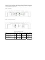
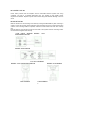
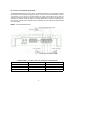
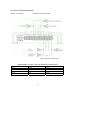
AUDIO SYSTEMS
OWNER'S MANUAL
AVA-250 AVA-450
AVA-550 AVA-650
AVA-700 AVA-750
AVA-800
TRI-MODE
CAPABLE
SIMUTANEOUS
STEREO &
BRIDGED
OPERATIONS
|CES98|
Thank you for purchasing a BOSS car audio amplifier, The BOSS amplifiers were engineered and
designed in the U.S.A. to the highest quality level and will provide you with years of high quality
sound level amplification and reproduction.
MODEL : AVA-650/800
MODEL : AVA-250/450/550/700/750
AMPLIFIER SPECIFICATIONS
Model
AVA-250
AVA-450
AVA-550
AVA-650
AVA-700
AVA-750
AVA-800
RMS Watts per Channel. 4 Ohms RMS
Watts per Channel, 2 Ohms
60x2 90x2
75x2
110x2
100x2
150x2
75x4
110x4
150x2
225x2
200x2
350x2
100x4
150x4
Max Watts per Channel, 4 Ohms
Bridgeoble Watts per Channel, 4 Ohms
Slqnal to Noise Ratio Freauency
R
H
KH
Distortion @RMS Watts Channel
Separation Damping Factor
240 120x 1 320 160x1 420 210x1 1000
650 325x1
90dB 9-50 90dB 9-50 90dB 9-50 500x2
90dB 9-50
90dB 9-50
-1
0.01%
90dB
>100+
0.01%
0.01%
90dB 100+ 90dB
100+
0.01%
90dB
125+
1200
1200
600x1
600x2
90dB 9-50 90dB 9-50
0.01%
0.01%
90dB 125+ 90dB
125+
0.01%
90dB 125+
Ill BUILT-IN ELECTRONIC CROSSOVER III
All BOSS amplifiers features built-in electronic crossovers.
The crossover frequency is adjustable from 45Hz to 120HZ (LPF) and from 80HZ to 500HZ (HPF)
at a 12dB octave slope. The crossover will now be in operation on both channels one and
two.
(AVA-250/450/650/700/750/800)
All BOSS amplifiers have been designed with fully regulated 100% MOSFET power supplies
assuring extremely quick switching response and self protection,
The output stages of all the BOSS amplifiers Implement discrete Darlington circuitry and were
designed to reduce and eliminate unwanted harmonic distortion.
Model :AVA-250
D 240 Watt Bridgeable Power Amplifier
D Power Output Per Channel: 60 Watts RMS
D Two Channel Bridgeable Amplifier
D Heavy Duty Aluminum Alloy Heatsink Chassis
D Class A-B Operation
D Built-in Electronic Crossover Network Adjustable from 40Hz~300Hz
D Continuously Variable Input Gain Adjustment
D Gold Plated RCA, Low Level High Impedance Input
D WIre Harness, High Level Low Impedance Input
D Remote Turn-on/Turn-off Circuit
D MOSFET Pulse Width Modulated Power Supply
D 2 Ohm Stable Operation with Output Power Increase
D Soft Turn-on Circuit
D Thermal Overheat Protection
0 Speaker Short Circuit Protection
D Input Overload Protection
D LED Diagnostic Condition Indicator
D Automotive Style Protection Fuses
D Upright Easy Access Speaker And Power/Ground/Remote Connection Terminals
D Power On LED Indicator
D Dimensions: 9" 1/8(W) x 2" 3/8(H) x 5" 4/8(L)
2-
Model:AVA-450
D 320 Watt Bridgeable Power Amplifier
D Power Output Per Channel: 75 Watts RMS
D Two Channel Bridgeable Amplifier
D Heavy Duty Aluminum Alloy Heatsink Chassis
D Class A-B Operation
D Built-in Electronic Crossover Network Adjustable from 40Hz~300Hz
D Continuously Variable Input Gain Adjustment
D Gold Plated RCA Low Level High Impedance Input
D Wire Harness, High Level Low Impedance Input
D Remote Turn-on/Turn-off Circuit
D MOSFET Pulse Width Modulated Power Supply
D 2 Ohm Stable Operation with Output Power Increase
D Soft Turn-on Circuit
D Thermal Overheat Protection
D Speaker Short Circuit Protection
D Input Overload Protection
D LED Diagnostic Condition Indicator
D Automotive Style Protection Fuses
D Upright Easy Access Speaker And Power/Ground/Remote Connection
Terminals
D Power On LED Indicator
D Dimensions: 9" 1 /8(W) x 2" 3/8(H) x 8" 1 /4(L)
Model :AVA-550
D 420 Watt Bridgeable Power Amplifier
D Power Output Per Channel: 100 Watts RMS
DTwo Channel Bridgeable Amplifier
D Heavy Duty Aluminum Alloy Heatsink Chassis
D Class A-B Operation
D Built-in Electronic Crossover Network Adjustable from 40Hz~300Hz
D Continuously Variable Input Gain Adjustment
D Gold Plated RCA Low Level High Impedance Input
D Wire Harness, High Level Low Impedance Input
D Remote Turn-on/Turn-off Circuit
D MOSFET Pulse Width Modulated Power Supply
D 2 Ohm Stable Operation with Output Power Increase
D Soft Turn-on Circuit
D Thermal Overheat Protection
D Speaker Short Circuit Protection
D Input Overload Protection
D LED Diagnostic Condition Indicator
D Automotive Style Protection Fuses
D Upright Easy Access Speaker And Power/Ground/Remote Connection
Terminals
D Power On LED Indicator
D Dimensions: 9" 1/8(W) x 2" 3/8(H) x 9" 7/8(L)
-3-
Model:AVA-650 D 1000 Wan Bridgeable Power
Amplifier
D Power Output Per Channel: 75 Watts RMS
D Four Channel Bridgeable Amplifier
D Tri-Way Configuration: 75Watts Per Channel into Four Channels, 160 Watts Per Channel
Into Two Channels, 75Watts Per Channel Into Two Channels plus 160 Watts into a Third
Channel
D Heavy Duty Aluminum Alloy Heatsink Chassis D Class AB Operation
D Built-in Electronic Crossover Network Adjustable from 40Hz~300Hz D
Continuously Variable Input Gain Adjustment D Gold Plated RCA, Low Level High
Impedance Input D Wire Harness, High Level Low Impedance Input D Remote
Turn-on/Turn-off Circuit D MOSFET Pulse Width Modulated Power Supply D 2
Ohm Stable Operation with Output Power Increase D Soft Turn-on Circuit D
Thermal Overheat Protection D Speaker Short Circuit Protection D Input Overload
Protection D LED Diagnostic Condition Indicator D Automotive Style Protection
Fuses
D Upright Easy Access Speaker And Power/Ground/Remote Connection Terminals D Power
On LED Indicator D Dimensions: 9" 1/8(W) x 2" 3/8(H) x 13" 3/4(L)
Model:AVA-700
D 650 Watt Bridgeable Power Amplifier
D Power Output Per Channel: 150 Watts RMS
D Two Channel Bridgeable Amplifier
D Heavy Duty Aluminum Alloy Heatsink Chassis
D Class A-B Operation
D Built-in Electronic Crossover Network Adjustable from 40Hz~300Hz
D Continuously Variable Input Gain Adjustment
D Gold Plated RCA, Low Level High Impedance Input
D WIre Harness, High Level Low Impedance Input
D Remote Turn-on/Turn-off Circuit
D MOSFET Pulse Width Modulated Power Supply
D 2 Ohm Stable Operation with Output Power Increase
D Soft Turn-on Circuit
D Thermal Overheat Protection
D Speaker Short Circuit Protection
D Input Overload Protection
D LED Diagnostic Condition Indicator
D Automotive Style Protection Fuses
D Upright Easy Access Speaker And Power/Ground/Remote Connection Terminals
D Power On LED Indicator
D Dimensions: 9" 1 /8(W) x 2" 3/8(H) x 12" 13/16(L)
-4-
Model:AVA-750
D 800 Watt Bridgeable Power Amplifier
D Power Output Per Channel: 200 Watts RMS
DTwo Channel Bridgeable Amplifier
D Heavy Duty Aluminum Alloy Heatsink Chassis
D Class A-B Operation
D Built-in Electronic Crossover Network Adjustable from 40Hz~300Hz
D Continuously Variable Input Gain Adjustment
D Gold Plated RCA, Low Level High Impedance Input
D Wire Harness, High Level Low Impedance Input
D Remote Turn-on/Turn-off Circuit
D MOSFET Pulse Width Modulated Power Supply
D 2 Ohm Stable Operation with Output Power Increase
D Soft Turn-on Circuit
D Thermal Overheat Protection
D Speaker Short Circuit Protection
D Input Overload Protection
D LED Diagnostic Condition Indicator
D Automotive Style Protection Fuses
D Upright Easy Access Speaker And Power/Ground/Remote Connection Terminals
D Power On LED Indicator
D Dimensions: 9" 1/8(W) x 2" 3/8(H) x 17" 3/4(L)
Model :AVA-800
D 840 Watt Bridgeable Power Amplifier
D Power Output Per Channel: 100 Watts RMS
D Four Channel Bridgeable Amplifier
DTri-Way Configuration: 100 Watts Per Channel Into Four Channels, 220 Watts Per Channel
into Two Channels, 100 Watts Per Channel Into Two Channels plus 220 Watts into a Third
Channel
D Heavy Duty Aluminum Alloy Heatsink Chassis D Class
A-B Operation
D Built-in Electronic Crossover Network Adjustable from 40Hz~300Hz D
Continuously Variable Input Gain Adjustment D Gold Plated RCA, Low Level
High Impedance Input D WIre Harness, High Level Low Impedance Input D
Remote Turn-on/Turn-off Circuit D MOSFET Pulse Width Modulated Power
Supply D 2 Ohm Stable Operation with Output Power Increase D Soft Turn-on
Circuit D Thermal Overheat Protection D Speaker Short Circuit Protection D
Input Overload Protection D LED Diagnostic Condition Indicator D Automotive
Style Protection Fuses
D Upright Easy Access Speaker And Power/Ground/Remote Connection Terminals D power On
LED Indicator D Dimensions: 9" 1/8(W) x 2" 3/8(H) x 15" 23/32(L)
-5-
Ill A FEW WORDS ABOUT PROTECTION CIRCUITRY III
The protection circuitry will disable the amplifier if it senses an input overload, speaker short circuit
or extreme high temperature conditions. When the protection circuit Is in operation the LED
Indicator on the panel of the unit will light Indicating that the amplifier has gone Into a self
preservation mode. At this time please check your system to see what Is causing the protection
circuit to fire. The amplifier can be reset by turning the remote power off and then on again. If the
system shutdown because of a thermal overload condition, allow the amplifier to cool down before
restarting. If the amplifier shutdown because of an input overload or speaker short circuit please
be sure to correct these conditions before restarting the amplifier.
Ill AMPLIFIERS & 2-OHM OPERATION lll
AVA-250/450/550/650/700/750/800 All BOSS amplifiers were designed to operate efficiently at
loads down to 2 ohms. What this means Is that you can do an installation of FOUR-8 ohm
speakers per channel using parallel wiring or TWO-8 ohm speakers per channel in parallel.
Increasing the number of woofers per channel at low frequencies up to 100 Hz produces
an acoustic coupling effect. This acoustic coupling increases your power output by 3 dB per
speaker. This might not sound like a lot but to produce an additional 3 dB of music power should
be the equivalent of adding an additional 10 watts to each speakeri
When operating at 2 ohms, the amplifiers increase their power output by approximately 50
percent. The current draw of the amplifiers will also increase by about the same amount. Be sure
that you have enough current to run the amplifiers Into a 2 ohm load otherwise distorted music will
be reproduced.
PLEASE NOTE:
The gain control of any car audio amplifier should not be mistaken for a volume control. It is a
sophisticated device designed to match the output level of your source unit to the input level of the
amplifier. Do not adjust the level to maximum unless your input level requires it. Not following this
instruction will result in an input overload to the amplifier and high levels of distorted musical
reproduction,
For speaker level Input. Simply wire the speaker output leads from your source to the Input of the
amplifier. Make sure to wire the positive leads to the positive Inputs and the negative leads to the
negative inputs.
Ill ELECTRICAL WIRING III
All BOSS amplifiers are equipped with easy top access screw terminals. These terminals are 14 K
Gold Plated to insure excellent electrical contact and to resist corrosion. See FIGURE I for
electrical Installation of all amplifiers. We suggest using at least 8 gauge wire for the power and
ground connections. Wire the amplifier directly to the car battery. For the ground connection use
the shortest possible wire to a good chassis ground point. Wire the Remote connection to auto
start lead of your equalizer or power antenna.
-6-
Ill POWER FUSE III
Power fuses protects both this amplifier and the automobile electrical system from wrong
conditions. The fuse is a standard automotive type. The capacity is each Model current
requirement is different. Replace only with same current rating fuse otherwise damage or fire can
result.
Ill MOUNTING III
Mark the locations for the mounting screw holes by holding the AMPLIFIER in place and using a
scribe or one of the mounting screws inserted in each mounting hole in turn to mark the mounting
surface. If the mounting surface is carpeted, measure the hole centers and mark with a felt-tip
pen.
Drill pilot holes for the mounting screws into the holes of the system insert the mounting screws
into the holes and tighten them securely
LOW INPUT WIRING
250/450/550/700/750
MODEL:
AVA-
MODEL:AVA-650/800
LH!GJ±INPUTWIRING
MODEL: AVA-250/450/550/700/750
CAR STEREO
MODEL:AVA-650/800
CAR STEREO
-7-
Ill 2 SPEAKERS WIRING III
MODEL : AVA-250/450/550/700/750
III BRIDGED SPEAKERS WIRING
MODEL : AVA-250/450/550/700/750
CONNECT THE NEGATIVE SPEAKER
TERMINAL
TO
THE
NEGATIVE
TERMINAL OF R-CHANNEL ON THE
AMPLIFIER CONNECT THE POSITIVE
SPEAKER TERMINAL OF L-CHANNEL
ON THE AMPLIFIER
-8-
Ill TRI WAY SPEAKERS WIRING III
TRI MODE OPERATIONAL OUTPUT allows a Crossover (Subwoofer) to be operated in MONO
mode while the main speakers are playing in Stereo. Leave the Crossover (Subwoofer) switch on
"Full" position. Use a 100 Volt, non-polar capacitor tor a high pass crossover and a wire coil
(inductor) to block high frequencies from the Crossover (Subwoofer) as shown In the figure below,
Capacitor and inductor values as written in the below determine the crossover frequencies. The
front and rear channels of this amplifier have this capability. Only the rear left and right channels
are shown below.
MODEL : AVA-250/450/550/700/750
CAPACITOR HIGH PASS FILTER
COMPONENT VALUES FOR 6 dB PASSIVE CROSSOVER
FREQUENCY
80 Hz
100 Hz
120 Hz
150 Hz
INDUCTOR
7.5mH
6,5 mH
5,5 mH
4mH
CAPACITOR
470 uF
330 uF
330 uF
220 uF
9-
Ill 4 SPEAKERS WIRING 4 CHANNEL
MODEL : AVA-650/800
III BRIDGED SPEAKERS WIRING
MODEL : AVA-650/800
-10-
Ill TRI WAY SPEAKERS WIRING
MODEL : AVA-650/800
INDUCTOR LOW PASS FILTER
CAPACITOR HIGH PASS FILTER
COMPONENT VALUES FOR 6 dB PASSIVE CROSSOVER
FREQUENCY
80 Hz
100 Hz
120 Hz
150 Hz
INDUCTOR
7.5mH
6.5 mH
5.5 mH
4mH
CAPACITOR
470 UF
330 uF
330 uF
220 uF
-11 -
Ill POWER WIRING III
MODEL ; AVA-250/450/550/700/750
MODEL : AVA-650/800
-12-
Ill WARNINGS III
Investigate the layout of your automobile thoroughly before drilling or cutting any holes,
Take care when you work near the gas tanks, lines or hydraulic lines, and electrical wiring.
Dont use power amplifier unmounted. Attach this system securely to the automobile to
prevent damage, particularly in the event of am accident.
Dont mount this system so that the wire connections are unprotected or are subject to
pinching of damage from nearby objects.
The +12DC power wire must be fused at the battery positive terminal connection. Before
making or breaking power connections at this system power terminals, disconnect the
+12V wire at the battery end. Confirm your radio/cassette player and/or other equip Is
turned off while connecting the input jacks and speaker terminals.
If you need to replace the power fuse replace It only with fuse Identical to that supplied
with the system. Using a fuse of different type or rating may result In damage to this
system which isnt covered by the warranty.
13
Ill TROUBLE SHOOTING III
Before removing your Amplifier, refer to list bellow and follow suggested procedure. Speaker and
their wires be tested first.
No Output:
a, Confirm that all terminal strip connections are firmly connected.
b. Check in-line and built-in fuses. Both "+ 12V" and "RMT" terminals must have + 12 Volts to
chassis ground,
c. Confirm that signal source [Car Radio/deck. EQ, X-over etc.) is connected and is supplying
output signal.
To confirm that Amplifier only [Do not connect the other end of the patch cord]. Briefly tap the
center pin of each [disconnected) RCA plug on the other [disconnected) end with your finger.
This should produce a noise [feedback) in the speakers.
Only One Channel Works:
a. Confirm that speaker terminal strip connections are firmly connected. b. Check "BALANCE"
control on Car Stereo (or signal source) to verify It Is at mid-point. c. If using RCA Low-level Input,
reverse the Input plugs at the Amplifier (right to left or vice verse).
If the channel that Is silent reverses position, the problem Is In the Car StereofEQ, X-over,
or other signal source) or connecting cable.
Weak Output
a. Check Input Sensitivity control adjustment,
Noise in Audio
a. If noise Is a "whine" that goes up and down with engine, confirm that Amplifier and any
other sources unit (Radio, EQ, X-over etc.). is properly grounded. b. A "clicking" or "popping"
noise at a rate that follow engine speed is generally Confirm
that the vehicle is equipped with resistor plugs and plug wires. Or, ignition system may
need service. c. Speaker and input wires should not be routed next to wires that interconnect
light and
other accessories/equipment. d, If above steps do not Improve/clear noise Interference, the
system should be checked
by a professional mobile audio Installer.
-14-