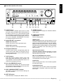
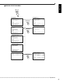
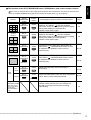
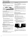
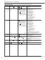
1
ENGLISH
OTHERS
DIGITAL RECORDER
INSTALLATION AND
OPERATION MANUAL
MODEL
DX-TL800E
THIS INSTRUCTION MANUAL IS IMPORTANT TO YOU. PLEASE READ IT BEFORE USING YOUR DIGITAL RECORDER.
1
Features
DX-TL800E Digital Recorder
Timer recording operation
By utilizing a new image compression/expansion
method (WAVELET method), high picture quality recording of more than 450 lines for the horizontal resolution and extended recording time are realized. The
DX-TL800E has an internal disk capacity of 80GB
and record in 5 user selectable picture grades and
8 recording time modes. The DX-TL800E also has
a built in 9 camera multiplexer with motion detection
per input. Individual field recording per input in both
standard and alarm recording are supported. Normal VCR like functions such as a JOG/SHUTTLE,
Menu, timer and rear terminals are featured.
• Timer recording program
4 types of camera patterns, recording intervals, recording picture quality for normal recording and
alarm recording can be registered for each operation. Furthermore, individual settings can be made
for pre-alarm recording and motion detection function as well.
• Timer holiday specification
Holidays throughout the year can be set in advance.
Built-in 9-input multiplexer functions
• Camera switching and split-screen display
Throughout terminals for non-simultaneous connection of 9 cameras. Split-screen modes of Single
screen, SPLIT4 or SPLIT9 screens for sequential
display.
• Motion detection
This function detects moving objects captured by
any of the 9 cameras connected to the unit, and initiates Alarm Recording. The following settings can
be made separately as desired : motion detection
area, detection area divided by 16 x 12 dots, sensitivity of motion detection, and minimum dot-count
for initiating Alarm Recording.
• Operation status display function
The operation status of this unit can be displayed
on the top or bottom of the screen.
Various recording functions
By completely separating normal recording settings
and alarm recording settings, further detailed settings are possible such as changing the recording
intervals only for the camera inputted with alarm signals while maintaining normal recording settings as
they are.
• Emergency recording
When there is input of an emergency signal, time recording is given first priority and is forcefully performed
in maximum intervals and maximum picture quality
using the camera specified for alarm recording or normal recording.
• Title/comment recording function
This unit can record characters inputted from a PC
with RS-232C connection as comments along with
the video/audio. When setting the display title, the
title can also be recorded along with the video. Display is also possible using another unit.
• Camera recording interval setting function
The recording intervals and recording picture quality can be set for each camera.
Versatile functions to support surveillance
• Audio recording function
1-channel PCM audio recording mode included.
• Image-alteration recognition function
Processing of each image recorded using a proprietary image-alteration recognition technology.
• Versatile high-speed search operation
Easy search functions using a proprietary algorithm.
Search options include Time Date, Skip, Index and
Alarm search. All search functions can specify a specific camera or ALL cameras to be used for the
search.
• Excellent expandablility
Standard RS-232C interface for remote PC control,
and various control terminals.
• Pre-alarm Recording function
Recording of images before the alarm sensor detects disturbances is also available.
• Front output terminals
Monitor or VCR can be connected on the front of
the unit.
• Compact Flash slot
The unit is equipped with a Compact Flash slot on
the front for recording to media and writing/reading
menu contents.
* Compact FlashTM is a trademark of SanDisk Corporation.
• Simultaneous recording/playback function
Recorded data on the hard disk can be played back
while recording.
• Variety of search functions
Pressing the SEARCH button on the front of the
unit displays the SEARCH menu for immediate
search operation. This function is convenient when
repeatedly performing searches.
•••••••••••••••••••••••••••••••••••••••••••••••••••••••••••••••••••••••••••••••••••••••••••••••••••••••••••••••••••••••••••••••••••••••••••••
2
ENGLISH
Caution and care
HEAVY OBJECTS SHOULD NEVER BE PLACED ON THE UNIT (E.G., TV)
NEVER TOUCH OR INSERT ANY OBJECT INSIDE THE UNIT
Touching the inside of the cabinet or inserting foreign objects of any kind not only creates a safety hazard but can also cause
extensive damage.
PROTECT THE POWER CORD
Damage to the power cord may cause fire or shock hazard. If the mains cord is damaged, switch off the mains outlet and carefully
unplug the cord by holding the mains plug.
UNPLUG THE POWER CORD DURING A LONG ABSENCE
Turn off the power and unplug the power cord during a long absence.
MAINTAIN GOOD VENTILATION
Do not obstruct the many ventilation holes on the unit. For maximum ventilation, leave some space around the unit and place the unit
on a hard level surface only, and ensure it is not covered during use. Heavy objects should never be placed on the unit.
WHEN NOT IN USE
When not in use always turn OFF the unit's POWER.
CABINET CARE
Never use petroleum-based cleaners. Clean with a soft cloth moistened with soap and water and wipe dry.
PVC cables or leads should not be left in contact with the cabinet surface for long periods.
INSTALLATION LOCATION
For excellent performance and lasting reliability install in a location that is:1.
Well ventilated, out of direct sunlight and away from direct heat.
2.
A solid vibration-free surface.
3.
Free from high humidity, excessive dust and away from magnetic fields.
4.
Please ensure that the ventilation fan located on the unit’s back panel is not blocked.
UNSUITABLE LOCATIONS
Placing the unit in the following places might shorten the product life:
•
Extremely cold places, such as refrigerated warehouses and ice houses
•
Places where excessive hydrogen sulfide is likely to be generated, such as hot-springs areas
•
Places or locations with salt air environment.
WARNING: TO PREVENT FIRE OR SHOCK HAZARD, DO NOT EXPOSE THIS APPARATUS TO RAIN OR
MOISTURE. THIS APPARATUS MUST BE GROUNDED.
MAINS LEAD CONNECTION
The mains lead on this Unit is fitted with a non-rewireable mains plug, incorporating a 5A fuse. If you need to replace the fuse,
use a 5A fuse approved by BSI or ASTA to BS 1362, ensuring you refit the fuse cover. If the mains plug is not suitable for the
sockets in your home, and you require to remove the plug, remove the fuse, cut off the plug then dispose of the plug immediately, to avoid a possible electric shock hazard. To refit a new plug, follow these instructions; Green-and-yellow: Earth, Blue:
Neutral and Brown: Live. As the colours in the mains lead of this Unit may not correspond with the coloured markings
identifying the terminals in your plug, proceed as follows.
•The wire which is coloured green-and-yellow must be connected to the terminal in the plug which is marked by the letter E or
by the safety earth symbol » or coloured green or green-and-yellow.
•The wire which is coloured blue must be connected to the terminal which is marked with the letter N or coloured black.
•The wire which is coloured blown must be connected to the terminal which is marked with the letter L or coloured red.
This Unit complies with the requirements of the EC Directive 89/336/EEC, “EMC Directive” , as amended by Directive 93/68/EEC.
The requirements for the susceptibility according to EN 55024 and the requirements for interference according to EN 55022 are
observed for the operation on residential areas, business, light industrial premises and in small scale enterprises, inside as well as
outside of the building. All places of operation are characterised by their connection to the public low voltage power supply
system. This unit is manufactured in accordance with EN 60950.
There may be cases when the unit’s built-in MOTION DETECTION function does not operate properly due to external condition
or video input signal or other factors.
The user will not be indemnified for problems (e.g., recording failure or playback failure) that occur with either the unit or a
connected device during operation. It is recommended that backups of important recordings are made regularly as a precaution
against possible breakdowns and accidents.
Recordable time and product warranty
Continuous recordable time and the estimated time displayed on the menu screen is the continuous recordable time when
operating this unit and is not the product warranty period. Furthermore, it is not the period that guarantees the operation of used
parts.
••••••••••••••••••••••••••••••••••••••••••••••••••••••••••••••••••••••••••••••••••••••••••••••••••••••••••••••••••••••••••••••• Beginning
3
Contents
Features .................................................................... 2
Caution and care ...................................................... 3
Contents .................................................................... 4
Major operations and their functions ..................... 6
Front View ..................................................................... 6
Rear View ................................................................... 8,9
Inserting/Ejecting Compact Flash Card ......................... 9
Basic Operations ............................................... 10-15
Multiplexer functions .................................................... 10
Multiplexer buttons ...................................................... 10
Menu settings .......................................................... 10,11
To return to the normal screen from a menu screen .... 11
DAYLIGHT SAVING ..................................................... 11
TIME DATE ADJUST ............................................... 11,12
Present time display .................................................... 12
Recorded capacity display function ............................. 12
Basic manual recording .......................................... 12-14
Setting the recording interval and
recording picture quality for normal recording .. 12-14
Basic playback ............................................................ 14
Basic search ........................................................... 14,15
TIME DATE SEARCH ............................................. 14,15
Flowchart ........................................................... 16,17
Flowchart for connection and settings .................... 16,17
Connections ...................................................... 18,19
Connecting to CCTV camera, monitor, sensor,
the electric power supply ........ 18
Alarm Recording Connection ...................................... 18
Connecting with an external recording device ............. 19
Initial settings ......................................................... 19
Initializing device ......................................................... 19
Menu functions .................................................. 20-23
MENU SETTING .................................................... 20-22
SEARCH SELECTION MENU .................................... 23
<TIME DATE/DISPLAY SETTINGS> .................. 24,25
TIME DATE ADJUST ................................................... 24
DISPLAY MODE .......................................................... 24
CLOCK LOCATION SETTING .................................... 24
CAMERA DISPLAY ..................................................... 24
CAMERA TITLE/MEMO SETTING ......................... 24,25
DUPLEX MODE DISPLAY .......................................... 25
<MPX DISPLAY SETTINGS> ............................. 26-29
Multiplexer function related button
operations/operation table ................. 26
Camera number button operations .............................. 26
SPLIT/SEQUENCE button operations ........................ 26
ZOOM button operations ............................................. 26
The function of the SPLIT/SEQUENCE button,
ZOOM button, and camera number buttons ...... 27
SPLIT4 SCREEN SETTING ........................................ 28
SPLIT9 SCREEN SETTING ........................................ 28
SEQUENCE SETTING ........................................... 28,29
INTERLASE ................................................................ 29
<MOTION DETECTION SETTINGS> ................. 29-31
SELECTION CAMERA NUMBER ............................... 29
MOTION DETECTION ........................................... 29,30
DETECTION MASK SETTING .................................... 30
SENSITIVITY .............................................................. 30
MOTION THRESHOLD .......................................... 30,31
TEST MODE ................................................................ 31
<RECORD SETTINGS>32,33
Settings concerning normal recording and
alarm recording .........
Recording mode settings for normal recording and
alarm recording .........
ALARM REC DURATION ............................................
PRE ALARM REC .......................................................
32
32
33
33
<TIMER PROGRAM SETTINGS> ...................... 34-36
TIMER PROGRAM SETTINGS ................................... 34
TIMER PROGRAM ................................................. 34,35
Structure of the <TIMER PROGRAM> screen ....... 34,35
HOLIDAY SETTING .................................................... 35
Recording mode settings A ~ D
for normal recording/alarm recording ........ 35
ALARM REC DURATION ............................................ 35
PRE ALARM REC ....................................................... 36
Overlapping Timer settings .......................................... 36
<INITIAL SET UP/INFORMATION> ................... 37-43
HDD SETTINGS ..................................................... 37,38
HDD REPEAT REC ..................................................... 37
HDD REPEAT PLAY .................................................... 37
IM-CHECK PLAY ......................................................... 37
SEQUENTIAL PLAY .................................................... 38
AUDIO RECORDING .................................................. 38
REAR TERMINAL SETTINGS ............................... 39-41
MODE OUT 1 ~ MODE OUT 4 .................................... 39
KEY SOUND ............................................................... 39
BUZZER ................................................................. 39,40
REMAIN HDD .............................................................. 40
CALL OUT SETTINGS ................................................ 40
HDD REMAIN .............................................................. 40
HDD FULL ................................................................... 41
EMERGENCY REC DURATION ................................. 41
RS-232C ................................................................. 41,42
MODE .......................................................................... 41
RS-232C SETTINGS .............................................. 41,42
INFORMATION/SERVICE ...................................... 42,43
HDD/CFC INFORMATION .......................................... 42
WARNING LOG LIST .................................................. 42
SETTING DATA INITIALIZE ................................... 42,43
HDD DATA CLEAR/CFC DATA CLEAR ....................... 43
<QUICK SETTINGS> .............................................. 43
QUICK SETTINGS ...................................................... 43
To update menu settings of this unit ............................ 43
To save menu settings of this unit
to a Compact Flash Card ........... 43
Operation examples44-47
Operation example 1 ................................................... 44
Operation example 2 .............................................. 45,46
Operation example 3 .............................................. 46,47
Various recordings ............................................ 48,49
PRE ALARM RECORDINGS ...................................... 48
EMERGENCY RECORDINGS .................................... 48
SERIES RECORDINGS ......................................... 48,49
Setting example for series recording 1 ................... 48,49
Setting example for series recording 2 ........................ 49
Various playback functions .............................. 50,51
Playing still frames ......................................................
Shuttle viewing/direct shuttle viewing ..........................
Shuttle hold .................................................................
Frame-by-frame palyback ...........................................
50
50
50
50
•••••••••••••••••••••••••••••••••••••••••••••••••••••••••••••••••••••••••••••••••••••••••••••••••••••••••••••••••••••••••••••••••••••••••••••
4
Various search ................................................... 52-55
SEARCH SELECTION ................................................ 52
SEARCH TYPE ........................................................... 52
SELECTION CAMERA NO. ........................................ 52
DATE/TIME .................................................................. 52
PLAYBACK DEVICE ................................................... 52
TIME DATE SEARCH .................................................. 53
INDEX SEARCH/ALARM INDEX SEARCH ........... 53,54
SKIP SEARCH ............................................................ 54
ALARM LIST SEARCH ........................................... 54,55
START/END SEARCH ................................................ 55
Pre-alarm recording time table ............................... 83,84
Without Audio recording, recording duration “LONG” .......... 83
Without Audio recording, recording duration “MEDIUM” ........ 83
Without Audio recording, recording duration “SHORT” .......... 84
With Audio recording, recording duration “LONG” ................. 84
With Audio recording, recording duration “MEDIUM” ............. 84
With Audio recording, recording duration “SHORT” ............... 84
ENGLISH
Reverse palyback ........................................................ 50
High-speed fast-forward/high-speed rewind ................ 50
Changing playback intervals .................................. 50,51
Monitor display settings and playback operation ......... 51
Simultaneous playback during recording .................... 51
Trubleshooting .................................................. 85,86
Warninigs and CALL OUT output ......................... 87
Warnings and their appropriate countermeasures ...... 87
Glossary .................................................................. 88
Glossary ...................................................................... 88
Relation of recording operation to the number of
cameras and recording interval settings ...... 88
Making copies ................................................... 56,57
Specifications ......................................................... 89
Copying from HDD to Compact Flash Card/
Restoring from Compact Flash Card to HDD ..... 56
Copying from unit to videotape ............................... 56,57
EMERGENCY/ALARM IN/REC/
CLOCK ADJ Input terminal ........ 89
MODE OUT1 - 4 Output terminal ................................ 89
CALL OUT Outpit terminal ........................................... 89
Other convenient functions ............................. 57-59
Power failure compensation circuit .............................. 57
Power failure reset recording ...................................... 57
Start time recording during power failure, etc. ............. 57
RESET button .............................................................. 57
SIMPLE LOCK/PASSWORD LOCK ....................... 57-59
SIMPLE LOCK ............................................................ 58
PASSWORD LOCK ................................................ 58,59
COVERT CAMERA SETTING ..................................... 59
ALARM DISPLAY ........................................................ 59
Connecting to a personal computer ..................... 60
Connecting with a personal computer .........................
Connection via modem ................................................
Direct connection .........................................................
RS-232C Terminal .......................................................
RS-232C Cable ...........................................................
60
60
60
60
60
Command codes ............................................... 61-79
RS-232C settings ........................................................ 61
Command code system ............................................... 61
Description of command code systems ....................... 61
Direct opration specification ........................................ 61
False operation panel command type ......................... 62
Status condition change information function .............. 62
Command receive confirmation function ..................... 62
Details of the numbers ................................................ 63
Command code ...................................................... 63-78
Character code list ...................................................... 79
How to read this manual
• Viewing displays
(Refer to this information when operating)
Reference information concerning operation is
described.
! (Caution required)
Cautionary items concerning operation are
described.
(See reference page)
Reference item and page number are indicated.
INFORMATION
(Reference)
Other reference information is described.
• Finding desired information
There is an index on the each right page of this
manual. There is also “Contents” at the
beginning of this manual. In addition, reference
pages are indicated throughout this manual.
• Troubleshooting
Read Troubleshooting (page 85, 86) for possible
remedies to the problem.
Comment search ............................................... 80,81
Comment search command code ............................... 80
Characters can be use for command search ............. 80
Sample opreation ........................................................ 81
Recording time table ......................................... 82-84
Continuous recording time table ............................. 82,83
HDD continuous recording time (for 80GB drive) ........ 82
Without Audio recording .............................................. 82
With Audio recording ................................................... 82
Compact Flash Card continuous recording time
(for 64MB drive) ....... 83
Without Audio recording .............................................. 83
With Audio recording ................................................... 83
••••••••••••••••••••••••••••••••••••••••••••••••••••••••••••••••••••••••••••••••••••••••••••••••••••••••••••••••••••••••••••••• Beginning
5
Major operations and their functions
■ Front View
1
4
3
2
5
6
7
REC/STOP
1
ACCESS
2
3
4
5
6
7
8
CLEAR/
REW
9
POWER
ENTER/
FF
TIMER
SPLIT/
SEQUENCE
ZOOM
PRE ALARM
M-DET
EMERGENCY
LOCK
DIGITAL RECORDER DX-TL800E
8
9
10 11 12 13 14
1. POWER button
When pressing this button while the MAIN switch on
the rear of this unit is set to ON, the power turns on
and the button lights. When the button is pressed
again, the unit will be in standby and the light will
turn off. When the unit is in operational transition
such as booting, the button will flash and other operations are not accepted.
7. JOG dial
Used to set various menus and search functions,
forwading or rewinding the image during playback
(field-by-field).
8. SPLIT/SEQUENCE button
Press the button to display SPLIT4 ,SPLIT9 screen
or SEQUENCE screen setting on multiplexer functions.
2. ACCESS indicator
Illuminates during access to hard disk drive or Compact Flash Card.
3. Camera number buttons (1 to 9)
Press the button to display the image of the camera
connected to this unit on the monitor.
4. TIMER button
When pressing this button, the unit is set to timer
recording/standby and the lamp flashes. When
pressing this button more than 1 second, timer recording/standby is canceled and the lamp turns off.
9. ZOOM button
When pressing this button once during single screen
display, the screen is magnified by 100%. In the same
way, pressing the button twice magnifies the screen
by 200% and pressing the button three times magnifies the screen by 400%. During single screen display, the magnification center point (X) is displayed
on the center of the screen. Pressing a camera
number button (1, 2, 3, or 4) will move the screen
according to the magnification center point as the
axis.
10. PRE ALARM indicador
5. REC/STOP button
When pressing this button, recording starts and the
button lights. When pressing the button for more than
1 second, the recording stops and the light turns off.
When pressing this button during alarm recording,
recording stops. During timer recording, recoding will
not stop even if the button is pressed.
6. SHUTTLE ring
Used to set various menus and search functions,
adjusting the playback speed, and rewinding or
forwading the image.
Illuminate during pre-alarm recording and pre-alarm
recording stand-by mode.
11. M-DET indicador
Illuminate when the motion detection function is on.
The lamp flashes when motion detection is in operation.
12. EMERGENCY indicador
Flashes during emergency recording and lights when
recording is completed.
13. LOCK indicador
Illuminates when simple lock or password lock is on.
•••••••••••••••••••••••••••••••••••••••••••••••••••••••••••••••••••••••••••••••••••••••••••••••••••••••••••••••••••••••••••••••••••••••••••••
6
ENGLISH
■ Front View (Inside of the door)
REC/STOP
1
ACCESS
2
3
4
5
6
7
8
9
EMERGENCY
LOCK
ENTER/
FF
CLEAR/
REW
POWER
TIMER
SPLIT/
SEQUENCE
ZOOM
PRE ALARM
M-DET
COPY
VIDEO OUT
AUDIO OUT
15
COMPACTFLASH
16
17
A.H.
W.R.
ALARM
HOLD
WARNING
RESET
SET UP
SEARCH
STOP
PAUSE
SHUTTLE
HOLD
18 19 20 21
14. LOCK button
Pressing it with a pointed object (such as a ballpoint pen) while the MAIN switch (main power) on
the back of the unit is on, will activate the simple
lock. Pressing it for more than 5 seconds will activate the PASSWORD SETTING display, which allows you to designate a PASSWORD. The indicator will light while the lock is active.
15. ANALOG OUT connectors
VIDEO OUT connector
Output connector for video signal (RCA pin).
AUDIO OUT connector
Output connector for audio signal (RCA pin).
REV. PLAY PLAY
PLAY
MODE
22
21. SEARCH button
Press this button to display the <SEARCH SELECTION> menu.
22. OPERATION buttons
STOP button
Press to stop playback.
PAUSE button
When pressing this button during playback, the unit
switches to still frame playback and the button lights.
When pressing this button again, the unit resumes
playback and the button turns off. When pressing
this button during shuttle playback, the set playback
speed is maintained even when letting go of the
SHUTTLE ring.
16. Compact Flash slot
Compact Flash Card for saving/loading data and
menus can be used. When not using the slot, attach the Compact Flash cover to prevent dust from
entering within the unit.
17. COPY button
Press this button to display <COPY> menu. This
button lights when performing copy operation. The
copy operation cannot be performed if there is no
media in the Compact Flash slot.
18. A.H. (ALARM HOLD) button
When pressing this button, the unit will not accept
alarm signals or motion detection for 5 minutes. During this time, the button will flash.
19. W.R. (WARNING RESET) button
SHUTTLE HOLD button
This button keeps the paticular playback or reverse
playback speed depending on the depree to which
the SHUTTLE ring is turnd.
REV. PLAY (REVERSE PLAY) button
When pressing this button, the unit switches to reverse playback and the button lights.
PLAY button
When pressing this button, the unit starts playback
and the button lights.
PLAY MODE buttons
These buttons can be used to switch the playback
interval while in playback mode and reverse playback mode.
This button is used to clear onscreen warning display and clear data.
20. SET UP button
Press this button to display the <MENU> menu.
••••••••••••••••••••••••••••••••••••••••••••••••••••••••••••••••••••••••••••••••••••••••••••••••••••••••••••••••••••••••••••••• Beginning
7
Major operations and their functions (continued)
■ Rear View
2
1
3
4
ON
MAIN
Y/C
OFF
1
2
3
1
2
3
4 CAMERA IN 5
6
7
8
9
4 CAMERA OUT 5
6
7
8
9
VIDEO OUT
1
2
3
4
5
6
7
8
9
100V
ALARM IN
OUT AUDIO IN
MIC
RESET
RESET
8
9
CLOCK ADJ
REC
EMERGENCY
RESERVED
MODE OUT 1
MODE OUT 2
MODE OUT 3
MODE OUT 4
CALL OUT
CALL OUT GND
GND
MAX 30mA
DC 5V OUT
AC IN~
RS-232C
RS-232C
GND
5
6
7
1. MAIN switch
This is the main power switch. When using this unit,
set this switch to ON. Otherwise, the power cannot
be turned on/off using the POWER button on the front
of the unit.
10
11
12
6. AUDIO connectors
AUDIO IN connector
Input connector for audio signal (RCA pin).
AUDIO OUT connector
Output connector for audio signal (RCA pin).
2. VIDEO connectors
VIDEO OUT connector
Output connector for video signal to monitor (BNC
connector).
7. GND terminals
Ground terminal for the alarm signal.
8. MIC jack
S(Y/C) OUT connector
These are output terminals for video signals that
separate brightness signals and color signals for
higher picture quality. Simultaneous output along with
VIDEO OUT is also possible.
3. CAMERA IN connectors
Input connector for microphone (600 ohm impedance).
9. RESET button
Pressing this button resets the unit and the power
turns off. If this case, video data, menu settings and
the current time are kept.
Input connector for signal of camera (BNC connector).
4. CAMERA OUT connectors
Camera video output terminals for use of BNC connectors. Output connector for signal of camera which
is provided via CAMERA IN (BNC connector).
5. AC power socket
This socket connects to the power cord. Earth terminal is for safety. Use the 100 ~ 240V plug with
earth for the power of this unit.
If there is no ground terminal on the wall outlet,
contact your dealer of purchase for grounding work
(with charge). When there is no ground terminal in a
wall socket, please request ground construction from
a store. (It is a charge.) Do not connect the earth
terminal of a plug to gas pipe, water pipe, lightning
rod and so on.
!
10. ALARM IN terminals
Input terminal for alarm signal.
11. I/O terminals
CLOCK ADJ terminal
Input terminal to set the present time. Time display
is adjusted to the nearest hour (00 minutes 00 seconds) when this terminal receives the CLOCK ADJ
signal.
INFORMATION
The on-screen clock can be reset to the nearest hour,
by applying a signal to the CLOCK ADJ terminal. For
example, if the current time is 11:29:59, it will be reset
to 11:00:00, and if the current time is 11:30:00, it will be
reset to 12:00:00.
•••••••••••••••••••••••••••••••••••••••••••••••••••••••••••••••••••••••••••••••••••••••••••••••••••••••••••••••••••••••••••••••••••••••••••••
8
■ Inserting/Ejecting Compact Flash Card
ENGLISH
REC terminal
Input terminal to start recording. Not available during timer recording.
! Before use, read the cautionary notes described in
the manual included with Compact Flash Card.
EMERGENCY terminal
Input terminal for starting emergency recording.
<Inserting Card>
RESERVED terminal
Not available.
2. With the label facing up, securely insert the Card in the
direction of the arrow until the EJECT button pops out.
MODE OUT 1 ~ MODE OUT 4 terminal
Output terminal to indicate the unit’s current mode.
Select the unit’s condition by MODE OUT 1 ~ MODE
OUT 4 setting in the <REAR TERMINAL SETTINGS>
menu.
CALL OUT terminal / CALL OUT GND terminal
This is the ISOLATION output terminal. Output terminal and its GND terminal to indicate information
such as “HDD FULL”. Information that can be transmitted externally consists of CALL OUT settings
made on the REAR TERMINAL SETTINGS menu
screen as well as fixed output settings.
DC 5V OUT terminal
Will only output when both the MAIN switch and
POWER button are ON. The maximum electric current is 30mA.
1. Remove the Compact Flash cover attached to the unit.
! Do not eject the Card when copying/restoring, copying/loading menus, or immediately after inserting the
card. The Card or the contained data may become damaged.
! Securely insert the Compact Flash Card. Otherwise,
the unit may not work properly.
! Use a Compact Flash Card specified by Mitsubishi.
Otherwise, reading/writing of data may not work properly. For details, contact your dealer of purchase.
! When using a new Card, be sure to execute CFC
DATA CLEAR in the <INFORMATION/SERVICE>
screen.
<Ejecting Card>
1. Press the EJECT button and eject the Card.
2. Attach the Compact Flash cover.
12. RS-232C socket
This terminal is used to connect to host device with
RS-232C terminal. This unit can be controlled by the
other device through this terminal.
REC/STOP
1
ACCESS
2
3
4
5
6
7
8
TIMER
SPLIT/
SEQUENCE
ZOOM
PRE ALARM
COPY
VIDEO OUT
SPLIT/
SEQUENCE
ENTER/
FF
CLEAR/
REW
9
POWER
AUDIO OUT
COMPACTFLASH
M-DET
EMERGENCY
LOCK
SET UP
SEARCH
STOP
PAUSE
SHUTTLE
HOLD
REV. PLAY PLAY
PLAY
MODE
EJECT Button
ZOOM
COPY
VIDEO OUT AUDIO OUT
CompactFlash media
••••••••••••••••••••••••••••••••••••••••••••••••••••••••••••••••••••••••••••••••••••••••••••••••••••••••••••••••••••••••••••••• Beginning
9
Basic Operations
■ Multiplexer functions
Buttons on the front of the unit can be used to perform
some of the multiplexer functions.
! Multiplexer functions are not available when the
PLAY button is on.
♦ Multiplexer buttons
SPLIT/
SEQUENCE
2
3
4
5
6
7
8
• The <SETTINGS> screen appears.
9
MOVE button
ZOOM
• “SETTING UP...” appears on the screen and the unit is
booted.
• POWER button operation will not be accepted while the
ACCESS indicator is flashing. Press the POWER button after
the indicator turns off.
2. After boot-up, press a SET UP button inside the door on
the front of the unit.
1 Camera number button (1 to 9)
1
1. Set the MAIN switch on the rear of the unit to ON. Press
the POWER button on the front after the ACCESS indicator
turns off.
<SETTINGS>
>>TIME DATE/DISPLAY SETTINGS
MPX DISPLAY SETTINGS
MOTION DETECTION SETTINGS
RECORD SETTINGS
TIMER RPOGRAM SETTINGS
INITIAL SET UP/INFORMATION
QUICK SETTINGS
3 ZOOM button
2 SPLIT/SEQUENCE button
MEMO:
1. Camera number buttons (1 ~ 9)
Video images of cameras connected to CAMERA IN terminals 1 ~ 9 on the rear of the unit are displayed.
By pressing a camera number button, video can
be displayed even if the camera is not set for recording.
2. SPLIT/SEQUENCE button
The screen switches in order of SPLIT9 set in the <MPX
DISPLAY> screen, 3 types of SPLIT4 SEQUENTIAL (a, b,
c), SPLIT4 SEQUENTIAL, and SINGLE SEQUENTIAL.
(SEQUENTIAL display is skipped during playback.)
3. ZOOM button
When this button is pressed during single screen display,
MAGNIFICATION 100% screen appears and the magnification center point (X) is displayed at the center. Pressing
the button again will switch the magnification to 200% and
then 400%. By pressing the MOVE buttons, the magnified
screen can be moved vertically/horizontally with the center
see “ZOOM button operations,” page
point as the axis (
26).
When the ZOOM button is pressed, camera number
buttons 1 ~ 4 switches to the MOVE buttons.
■ Menu settings
3. Check to see that the cursor (>>) is positioned at “TIME
DATE DISPLAY”, and then turn the SHUTTLE ring clockwise.
• The <TIME DATA/DISPLAY SETTINGS> screen appears (
see page 24).
<TIME DATE/DISPLAY SETTINGS>
>>TIME DATE ADJUST
DISPLAY MODE
1
CLOCK LOCATION SETTING
CAMERA DISPLAY
NUMBER
CAMERA TITLE/MEMO SETTING
DUPLEX MODE DISPLAY
BOTTOM
<MODE1>
01-01-2002 00:00:00
4. Turn the JOG dial to move the cursor to “DISPLAY MODE”
and turn the SHUTTLE ring clockwise.
• The background of the “DISPLAY MODE” setting turns red
and flashes.
When turning the JOG dial clockwise, the cursor
(>>) moves down. When turning counterclockwise,
the cursor (>>) moves up.
5. Turn the JOG dial to display “3”.
The operational conditions of this unit can be set in the
menu screens according to use. Although the setting
method will differ slightly depending on the menu screen,
the basic setting method of using the JOG dial and SHUTTLE ring will be used for setting the display mode as an
example.
SHUTTLE ring
When a SET UP button is pressed and the menu
screen appears, the background darkens and the
displayed characters become easier to see.
JOG dial
• The display mode sample on the bottom of the screen
changes to <MODE3>.
6. Turn the SHUTTLE ring clockwise.
• The setting is confirmed and flashing stops.
• To continue with other settings, repeat steps 4 and 5.
When turning the SHUTTLE ring counterclockwise
while the setting is flashing, the setting will return to
the previous setting. To exit the screen, turn the SHUTTLE ring counterclockwise.
Example : Set DISPLAY MODE to “3” (default : “1”).
••••••••••••••••••••••••••••••••••••••••••••••••••••••••••••••••••••••••••••••••••••••••••••••••••••••••••••••••••••••••••••••••••••••••••••••
10
<MODE3>
<TIME DATE ADJUST>
>>DAYLIGHT SAVING
DAY
MONTH
YEAR
TIME
ENGLISH
<TIME DATE/DISPLAY SETTINGS>
>>TIME DATE ADJUST
DISPLAY MODE
3
CLOCK LOCATION SETTING
CAMERA DISPLAY
NUMBER
CAMERA TITLE/MEMO SETTING
DUPLEX MODE DISPLAY
BOTTOM
OUT
01
01
2002
00:00:00
4. Check to see that the cursor (>>) is positioned at “DAY”,
and then turn the SHUTTLE ring clockwise.
• The background of “DAY” changes to red and flashes.
01-01-2002 TUE
00:00:00 30P
99% A00001
♦ To return to the normal screen from a menu screen
The procedure to return to the normal screen after completing menu screen settings using the JOG dial/SHUTTLE ring is explained.
1. Check to see that the setting item is no longer flashing and
the item has been changed to the desired setting.
• The setting has not been confirmed if the item is flashing.
Refer to the above setting procedure to confirm the setting.
• To continue with other settings or to check the setting item,
turn the SHUTTLE ring counterclockwise once to return to
the previous screen.
<TIME DATE ADJUST>
DAYLIGHT SAVING
>>DAY
MONTH
YEAR
TIME
OUT
01
01
2002
00:00:00
5. Turn the JOG dial to display “28” and turn the SHUTTLE
ring clockwise.
• The setting is confirmed and flashing stops.
<TIME DATE ADJUST>
DAYLIGHT SAVING
>>DAY
MONTH
YEAR
TIME
OUT
28
01
2002
00:00:00
This operation is not accepted when the setting
item is flashing.
6. Turn the JOG dial clockwise to move the cursor (>>) to
“MONTH”.
2-1. (To return to the normal screen by moving up menu
screens one at a time • • • )
When turning the JOG dial clockwise, the cursor
(>>) moves down. When turning counterclockwise,
the cursor (>>) moves up.
• Turn the SHUTTLE ring counterclockwise for the amount of
menu screens opened. The previous menu screen is
displayed every time the SHUTTLE ring is turned
counterclockwise.
2-2. (To directly return to the normal screen • • • )
• Press the SET UP button to clear the menu screen and return
to the normal screen.
! The menu screen will not be cleared even when
pressing the SET UP button when the setting item
is flashing.
♦ DAYLIGHT SAVING
The clock is put forward one hour by setting the menu.
The default setting for this function is “OUT”. On the DAYLIGHT SAVING in <TIME DATE ADJUST> menu, turn the
JOG dial to flash “IN” (the daylight saving function is activating) and turn the SHUTTLE ring clockwise to enter the
selection.
♦ TIME DATE ADJUST
! Before starting recording, it is necessary to set
accurately the current date and time.
Example : Set the date/time to 28/10/2002 6:30pm
(18:30)(default : “01/01/2002 00:00:00”).
1. Press the SET UP button to display the <SETTINGS>
screen.
2. Check to see that the cursor (>>) is positioned at “TIME
DATE/DISPLAY SETTINGS”, and then turn the SHUTTLE ring
clockwise.
• The <TIME DATE/DISPLAY SETTINGS> screen appears.
3. Turn the JOG dial to move the cursor to “TIME DATE
ADJUST” and turn the SHUTTLE ring clockwise.
7. Repeat steps 4 ~ 6 to set “MONTH” and “YEAR”.
8. Turn the JOG dial to move the cursor (>>) to “TIME” and
turn the SHUTTLE ring clockwise twice.
• The “TIME” display reverses in color when the SHUTTLE
ring is turned the first time. When the ring is turned for the
second time, the display turns red and flashes.
<TIME DATE ADJUST>
DAYLIGHT SAVING
DAY
MONTH
YEAR
>>TIME
OUT
01
01
2002
00:00:00
9. Turn the JOG dial to display “18” and turn the SHUTTLE
ring clockwise.
• The setting is confirmed and flashing stops.
<TIME DATE ADJUST>
DAYLIGHT SAVING
DAY
MONTH
YEAR
>>TIME
OUT
01
01
2002
18:00:00
The time is indicated using the 24-hour system.
10. Repeat steps 8 and 9 to set “MINUTE” and “SECOND”.
11. Turn the SHUTTLE ring clockwise.
• The setting is confirmed and flashing stops.
<TIME DATE ADJUST>
DAYLIGHT SAVING
DAY
MONTH
YEAR
>>TIME
OUT
01
01
2002
18:30:00
• The <TIME DATE ADJUST> screen appears.
••••••••••••••••••••••••••••••••••••••••••••••••••••••••••••••••••••••••••••••••••••••••••••••••••••••••••••••••••••• Basic Operations
11
Basic Operations (continued)
12. Turn the SHUTTLE ring counterclockwise or press the SET
UP button.
2) Select “3” for “DISPLAY MODE” in the <TIME DATE/
DISPLAY SETTINGS> screen (
see page 24).
♦ Present time display
■ Basic manual recording
When turning on the unit power, the time/date display shown
below appears (in the case of DISPLAY MODE 3).
Normal recording using manual operation is explained here.
Before starting recording, recording settings must be
checked. After checking the settings of “HDD REPEAT
REC” in the <HDD SETTINGS> screen (
see page 37),
the REC mode settings are made.
For setting other display modes, “DISPLAY
MODES”,
see page 24.
During recording, the used HDD space is displayed. When recording is stopped, the display is
cleared (with the exception of when pausing recording). The HDD usage display appears again after a
few moments when recording is started once more.
! Settings here are for normal recording only. For
timer recording, settings must be made on the
see
<TIMER PROGRAM SETTINGS> screen (
page 34).
♦ Setting the recording interval and recording picture
quality for normal recording
INFORMATION
To perform normal recording, “PPS” and “GRADE” must
be set for each camera.
This unit uses 4 digits to display the year. The
allowed display range is 99 years between 1/1/
2002 ~ 12/31/2100. The unit is also equipped with
a function to automatically calculate leap years.
The date returns to the year 2002 after 12/31/
2100.
Setting of “PPS” (default : “12.5P”).
“25P”, “12.5P”, “8.33P”, “6.25P”, “5P”, “4.17P”,
“3.13P”, “2.5P”, “1P”, “0.5P”, “0.25P”, “0.13P”,
“- - - - -”
“- - - - -” : Recording cannot be performed with camera set to this item.
Day of
Recorded capacity of
Date Month Year the week the Hard Disk
01 - 01 - 2002 TUE
00 : 00 : 00 12.5P
Minute
Time
! Available recording intervals will vary according
to the number of cameras operating or ALARM RECORDING settings (
see page 32). Interval displays will be according to the chart below.
10% A00001
Recording interval
Alarm recording number
Second
♦ Recorded capacity display function
This unit displays the used space of the specified recording device (HDD) on the screen when “REMAIN HDD” of
the <REAR TERMINAL SETTINGS> screen is set to “HDD”.
The “%” indicates the ratio detected as HDD against the
total HDD capacity. The following settings are required to
enable this function.
1) Select the device and set the remaining capacity using
“REMAIN HDD” of the <REAR TERMINAL SETTINGS>
screen (
see page 40).
Setting of “GRADE” (default : “STD”).
“SUPER”, “HIGH”, “STD”(STANDARD), “BASIC”,
“LONG”
Example : Set “PPS” of camera number “ 1 ” to “0.56P”
and “GRADE” to “HIGH” for normal recording.
1. Press the SET UP button to display the <SETTINGS>
screen.
2. Turn the JOG dial to move the cursor to “DISPLAY MODE”
and turn the SHUTTLE ring clockwise.
• The <RECORD SETTINGS> screen appears.
Relation between a number of operation cameras and a “PPS”
PPS
Number of
operation
cameras
LONG
SUPER
#1
#2
#3
#4
#5
#6
#7
#8
#9
25P
12.5P
8.33P
6.25P
5P
4.17P
3.13P
2.5P
1P
0.5P
0.25P
0.13P
12.5P
6.25P
4.17P
3.13P
2.5P
2.08P
1.56P
1.25P
0.5P
0.25P
0.12P
0.06P
8.33P
4.17P
2.78P
2.08P
1.67P
1.39P
1.04P
0.83P
0.33P
0.17P
0.08P
0.04P
6.25P
3.13P
2.08P
1.56P
1.25P
1.04P
0.78P
0.63P
0.25P
0.13P
0.06P
0.03P
5P
2.5P
1.67P
1.25P
1P
0.83P
0.63P
0.5P
0.2P
0.1P
0.05P
0.03P
4.17P
2.08P
1.39P
1.04P
0.83P
0.69P
0.52P
0.42P
0.17P
0.08P
0.04P
0.02P
3.57P
1.79P
1.19P
0.89P
0.71P
0.6P
0.45P
0.36P
0.14P
0.07P
0.04P
0.02P
3.13P
1.56P
1.04P
0.78P
0.63P
0.52P
0.39P
0.31P
0.13P
0.06P
0.03P
0.02P
2.78P
1.39P
0.93P
0.69P
0.56P
0.46P
0.35P
0.28P
0.11P
0.06P
0.03P
0.01P
••••••••••••••••••••••••••••••••••••••••••••••••••••••••••••••••••••••••••••••••••••••••••••••••••••••••••••••••••••••••••••••••••••••••••••••
12
5S
OFF
3. Check to see that the cursor is positioned at “RECORD
SETTING”, and then turn the SHUTTLE ring clockwise.
• The <RECORD SETTING> screen appears.
ENGLISH
<RECORD SETTINGS>
>>RECORD SETTING
ALARM REC DURATION
PRE ALARM REC
<RECORD SETTING>
ALARM PLUS
NO.PPS
GRADE A-PPS A-GRADE
1.39P STD
1 0.56P STD
STD
1.39P STD
2 1.39P
1.39P STD
3 1.39P STD
4 1.39P
STD
1.39P STD
STD
1.39P STD
5 1.39P
6 1.39P
STD
1.39P STD
STD
1.39P STD
7 1.39P
STD
1.39P STD
8 1.39P
STD
1.39P STD
9 1.39P
<ESTD TIME>
H M
7. Turn the JOG dial clockwise to reverse display “GRADE”
and turn the SHUTTLE ring clockwise.
• The background of the “GRADE” setting turns red and
flashes.
Camera selection during alarm recording
<RECORD SETTING>
ALARM PLUS
NO.PPS
GRADE A-PPS A-GRADE
>> 1 1.39P STD
1.39P STD
STD
1.39P STD
2 1.39P
1.39P STD
3 1.39P STD
4 1.39P
STD
1.39P STD
STD
1.39P STD
5 1.39P
6 1.39P
STD
1.39P STD
STD
1.39P STD
7 1.39P
STD
1.39P STD
8 1.39P
STD
1.39P STD
9 1.39P
<ESTD TIME>
H M
CAUTION : For <ESTD TIME>,
see “Continuous recording time table” , page 82.
4. Check to see that the cursor is positioned at “ 1 ”, and then
turn the SHUTTLE ring clockwise.
• The “PPS” setting reverses in color.
<RECORD SETTING>
ALARM PLUS
NO.PPS
GRADE A-PPS A-GRADE
1.39P STD
1 1.39P STD
STD
1.39P STD
2 1.39P
1.39P STD
3 1.39P STD
4 1.39P
STD
1.39P STD
STD
1.39P STD
5 1.39P
6 1.39P
STD
1.39P STD
STD
1.39P STD
7 1.39P
STD
1.39P STD
8 1.39P
STD
1.39P STD
9 1.39P
<ESTD TIME>
H M
5. Turn the SHUTTLE ring clockwise again.
• The background of the “PPS” setting turns red and flashes.
<RECORD SETTING>
ALARM PLUS
NO.PPS
GRADE A-PPS A-GRADE
1.39P STD
1 1.39P STD
STD
1.39P STD
2 1.39P
1.39P STD
3 1.39P STD
4 1.39P
STD
1.39P STD
STD
1.39P STD
5 1.39P
6 1.39P
STD
1.39P STD
STD
1.39P STD
7 1.39P
STD
1.39P STD
8 1.39P
STD
1.39P STD
9 1.39P
<ESTD TIME>
H M
! The menu screen will not be cleared even when
pressing the SET UP button when the setting item
is flashing.
6. Turn the JOG dial to select “0.56P” and turn the SHUTTLE
ring clockwise.
• Setting is confirmed and flashing stops.
<RECORD SETTING>
ALARM PLUS
NO.PPS
GRADE A-PPS A-GRADE
1.39P STD
1 0.56P STD
STD
1.39P STD
2 1.39P
1.39P STD
3 1.39P STD
4 1.39P
STD
1.39P STD
STD
1.39P STD
5 1.39P
6 1.39P
STD
1.39P STD
STD
1.39P STD
7 1.39P
STD
1.39P STD
8 1.39P
STD
1.39P STD
9 1.39P
<ESTD TIME>
H M
! When the setting item is flashing, the menu
screen cannot be cleared even when pressing the
SET UP button.
8. Turn the JOG dial to select “HIGH” and turn the SHUTTLE
ring clockwise.
• The setting is confirmed and flashing stops.
<RECORD SETTING>
ALARM PLUS
NO.PPS
GRADE A-PPS A-GRADE
1 0.56P HIGH 1.39P STD
STD
1.39P STD
2 1.39P
1.39P STD
3 1.39P STD
4 1.39P
STD
1.39P STD
STD
1.39P STD
5 1.39P
6 1.39P
STD
1.39P STD
STD
1.39P STD
7 1.39P
STD
1.39P STD
8 1.39P
STD
1.39P STD
9 1.39P
<ESTD TIME>
H M
About <ESTD TIME>
• The remaining recordable time is displayed as <ESTD TIME>
depending on the “PPS” and “GRADE” settings. (The time
will not change when changing the alarm recording settings.)
For details concerning the estimated recordable time,
see page 82.
9. When completed with setting, turn the SHUTTLE ring
counterclockwise.
• The cursor moves to the camera number on the left.
• When continuing with other camera number settings, turn
the JOG dial to move the cursor to the desired camera number
and repeat steps 4 ~ 8 to perform settings.
<RECORD SETTING>
ALARM PLUS
NO.PPS
GRADE A-PPS A-GRADE
>> 1 0.56P HIGH 1.39P STD
STD
1.39P STD
2 1.39P
1.39P STD
3 1.39P STD
4 1.39P
STD
1.39P STD
STD
1.39P STD
5 1.39P
6 1.39P
STD
1.39P STD
STD
1.39P STD
7 1.39P
STD
1.39P STD
8 1.39P
STD
1.39P STD
9 1.39P
<ESTD TIME>
H M
••••••••••••••••••••••••••••••••••••••••••••••••••••••••••••••••••••••••••••••••••••••••••••••••••••••••••••••••••••• Basic Operations
13
Basic Operations (continued)
10. Turn the SHUTTLE ring counterclockwise or press the SET
UP button to return to the normal screen.
1. Press the SEARCH button to display the <TIME DATE
SEARCH> screen.
• The default setting of the search menu displayed when
pressing the SEARCH button is “TIME DATE SEARCH”.
11. Press the REC/STOP button.
• REC/STOP button light turns on and recording starts.
<TIME DATA SEARCH>
12. To stop recording, press the REC/STOP button for more
than 1 second.
• Recording stops and the REC/STOP button light turns off.
>>01-01-2002
00:00:00
EXECUTE(FORWARD)
REC/STOP
START
END
This unit allows recorded video to be played back using
various methods. The basic playback described here is the
most common method for playback.
1. Press the PLAY button within the door on the front of the
unit.
• Recorded contents of the HDD are played back.
• After turning the power on, the oldest recorded video is
played back first. Otherwise, playback resumes at the position
of the previous playback.
PAUSE
00:00:00
12:30:15
PUSH SEARCH KEY FOR
SEARCH SELECTION
■ Basic playback
STOP
02-02-2002
04-04-2002
REV. PLAY PLAY
When the “HDD REPEAT PLAY” setting in the
“HDD SETTINGS” is set to “OFF”, playback is
stopped when reaching the end of the physical HDD
or recorded section. When the “HDD REPEAT PLAY”
setting is set to “ON”, recorded video data is played
back repeatedly (
see “HDD REPEAT PLAY”,
page 37).
!
2. Check to see that the cursor is next to the search date and
turn the SHUTTLE ring clockwise twice.
• The display reverses in color when the SHUTTLE ring is
turned the first time. When the ring is turned for the second
time, the display turns red and flashes.
3. Turn the JOG dial to display “03” for “DATE” and turn the
SHUTTLE ring clockwise.
• Setting is confirmed and flashing stops.
4. Turn the JOG dial to reverse display “MONTH” and turn the
SHUTTLE ring clockwise.
• The background of the setting item changes to red and
flashes.
5.Turn the JOG dial to display “03” for “MONTH” and turn the
SHUTTLE ring clockwise.
• Setting is confirmed and flashing stops.
6. Repeat steps 4 and 5 to set “YEAR”, “HOUR”, “MINUTE”
and “SECOND”.
<TIME DATA SEARCH>
>>03-03-2002
1-1. Changing the playback device.
• The default setting of the playback device is HDD.
• When changing the playback device to Compact Flash Card,
press the SEARCH button twice (
see page 52) to display
the <SEARCH SELECTION> screen and select “CFC”
(Compact Flash Card) in “PLAYBACK DEVICE”.
2. To pause playback, press the PAUSE button.
• To resume playback, press the PAUSE button again or press
the PLAY button.
3. To stop playback, press the STOP button.
• During HDD playback/pause, playback will start the next
time from the paused position.
• During CFC playback/pause, playback will start the next time
from the oldest recorded video on the media.
■ Basic search
This unit displays a menu of most used search functions
simply by pressing the SEARCH button.
♦ TIME DATE SEARCH
On this unit, various search functions are available for
searching the beginning of video clips. In this section, the
most common search method referred to as time/date
search is explained. With this method, searching is possible by date, hour, minute and specified camera number.
Example : Search a scene recorded on the HDD with
time/date stamp of 03/03/2002 9:25:40pm (21:25:40)
using camera number “ 3 ”.
21:25:40
EXECUTE(FORWARD)
START
END
02-02-2002
04-04-2002
00:00:00
12:30:15
PUSH SEARCH KEY FOR
SEARCH SELECTION
To exit the <SEARCH> screen without searching, turn the SHUTTLE ring counterclockwise or
press the SEARCH button twice.
For details concerning <SEARCH SELECTION>
for selecting search functions,
see page 52.
7. Press the SEARCH button to display the <SEARCH
SELECTION> screen.
8. Check to see that the cursor is positioned at “SELECTION
CAMERA NO. ”, and then turn the SHUTTLE ring clockwise.
• The background of the setting item changes to red and
flashes.
9. Turn the JOG dial to select “ 3 ” and turn the SHUTTLE ring
clockwise.
• Setting is confirmed and flashing stops.
• Setting (default : “ALL”)
“ALL”, “ 1 ”, “ 2 ”, “ 3 ”, “ 4 ”, “ 5 ”, “ 6 ”, “ 7 ”,
“ 8 ”, “ 9 ”
“ALL” : Search is conducted for all camera number “ 1 ” ~
“ 9 ”.
••••••••••••••••••••••••••••••••••••••••••••••••••••••••••••••••••••••••••••••••••••••••••••••••••••••••••••••••••••••••••••••••••••••••••••••
14
PLAYBACK DEVICE
START
END
02-02-2002
04-04-2002
HDD
00:00:00
12:30:15
! To display a single screen by selecting a camera
number from the SPLIT9 screen of the search result when “ALL” is selected in the “SELECTION
CAMERA NO.” setting, press the SEARCH button
to clear the <SEARCH> menu and press the desired camera number button. The desired video is
displayed in single screen.
ENGLISH
<SEARCH SELECTION>
SEARCH TYPE
TIME DATE
3
>>SELECTION CAMERA NO.
13. To playback the searched image.
• Press either the PLAY button or the PAUSE button.
10-1. (To change the playback device • • • )
Turn the JOG dial to select “PLAYBACK DEVICE” and turn
the SHUTTLE ring clockwise.
03-03-2002 21:25:40
• The background of the setting item changes to red and
flashes. Turn the JOG dial to display the desired playback
device and confirm.
• Setting (default : “HDD”)
“HDD” : Select when playing back HDD contents.
“CFC” : Select when playing back Compact Flash Card
contents.
3
10-2. (To change the search type • • • )
Turn the JOG dial to select “SEARCH TYPE” and turn the
SHUTTLE ring clockwise.
For playback,
tions”, pages 50,51.
• The background of the setting item changes to red and
flashes. Turn the JOG dial to display the desired search menu
and confirm.
• Setting (default : “TIME DATE”)
“TIME DATE”, “INDEX”, “ALARM INDEX”, “ALARM SKIP”,
“ALALRM LIST”.
11. When completed with setting, turn the SHUTTLE ring
counterclockwise.
PLAY
see “Various playback func-
14. To stop playback/still frame playback, press the STOP
button.
• The display returns to the normal screen.
15. Press the SEARCH button to clear the <SEARCH
SELECTION> screen.
• The display returns to the <TIME DATE SEARCH> screen
and the cursor appears on the left of the search date.
12. Turn the JOG dial to select “EXECUTE(FORWARD)” and
turn the SHUTTLE ring clockwise.
• The TIME DATE SEARCH begins the video of the set date/
time (or the video closest to the search) will appear in still
frame.
• The search result will appear using SPLIT9 screen when
“ALL” is selected in “SELECTION CAMERA NO.” of the
“SERACH SELECTION” screen. If camera number has been
selected individually, the still frame will be displayed in a
single screen.
<SEARCH SELECTION>
SEARCH TYPE
TIME DATE
3
SELECTION CAMERA NO.
>>PLAYBACK DEVICE
START
END
02-02-2002
04-04-2002
HDD
00:00:00
12:30:15
When there is no recording of the set time, the
video of the close time and date for the set camera
number will be displayed in still frame.
Depending on the recording condition, TIME
DATE SEARCH may not operate correctly.
••••••••••••••••••••••••••••••••••••••••••••••••••••••••••••••••••••••••••••••••••••••••••••••••••••••••••••••••••••• Basic Operations
15
Flowchart
■ Flowchart for connection and settings
Installation example :
Connect the terminals on the back ; and set initial settings. Next, make an alarm recording using the timer function, and
using alarm list search, retrieve, playback, and copy the data.
Connection the terminals on the back
• Connection the terminal on the back.
See “■ Connnecting to CCTV camera, monitor, sensor, the electric power supply”, page 18.
• Connection the alarm recording.
See “■ Alarm Recording Connection”, page 18 and “■ Rear View” , page 8, 9.
The unit is booted.
Changing the initial menu settings
• Setting the present time and screen display.
See “<TIME DATE/DISPLAY SETTINGS>”, pages 24, 25.
• Setting the present time.
See “♦ TIME DATE ADJUST”, pages 11,12.
• Setting the display mode.
See “■ DISPLAY MODE”, page 24.
• Setting the audio recording.
See “■ AUDIO RECORDING”, page 38 and “■ Continuous recording time table”, page 82.
Setting the HDD (hard disk drive) mode
• Setting the repeat recording.
See “■ HDD REPEAT REC”, page 37.
• Setting the remain HDD capacity.
See “■ REMAIN HDD”, page 40.
• Setting the call out.
See “• HDD REMAIN”, page 40 and “• HDD FULL”, page 41.
• Setting the buzzer.
See “■ BUZZER”, pages 39, 40.
Changing the multiplexer function
• Changing the split4 screen and split9 screen setting.
See “■ SPLIT4 SCREEN SETTING”, page 28 and “■ SPLIT9 SCREEN SETTING”, page 28.
• Changing the sequence setting.
See “■ SEQUENCE SETTING”, pages 28, 29.
Setting other various functuon
• Changing the screen display mode.
See “■ CLOCK LOACTION SETTING”, page 24 and “■ DUPLEX MODE DISPLAY”, page 25.
• Setting the camera title/memo.
See “■ CAMERA TITLE/MEMO SETTING”, pages 24, 25 and “■ CAMERA DISPLAY”, page 24.
• Setting the unit status outputted.
See “♦ MODE OUT 1 ~ MODE OUT 4”, page 39.
Setting the motion detection
• Selecting the camera number.
See “■ SELECTION CAMERA NUMBER”, page 29.
• Settinig the active/inactive of detection function.
See “■ MOTION DETECTION”, pages 29, 30.
• Setting the detection area.
See “■ DETECTION MASK SETTING”, page 30.
• Setting the sensitivity.
See “■ SENSITIVITY”, page 30.
• Setting the minimum number of dots for starting the motion detection operation.
See “■ MOTION THRESHOLD”, pages 30, 31.
•••••••••••••••••••••••••••••••••••••••••••••••••••••••••••••••••••••••••••••••••••••••••••••••••••••••••••••••••••••••••••••••••••••••••••
16
ENGLISH
Settings concerning timer recording
• Selecting the normal & alarm recording or pre-alarm recording.
See “■ Recording mode settings A ~ D for normal recording/alarm recording”, page 35.
• Setting the recording mode.
• Selecting the camera sellection during the alarm recording.
See “■ Recording mode settings for normal recording and alarm recording”, page 32.
• Setting the interval/picture grade for normal recording.
See “■ Setting the recording interval and recording picture quality for normal recording”, pages 12-14.
• Setting the interval/picture grade for alarm recording.
See “■ Setting the recording interval and recording picture quality for normal recording”, pages 12-14.
• Setting the duration of alarm recording.
See “■ ALARM REC DURATION”, page 35.
• Setting thr duration of pre-alarm recording.
See “■ PRE ALARM REC”, page 36 and “■ Pre-alarm recording time table”, pages 83, 84.
• Setting concerning timer program mode.
See “<TIMER PRODRAM SETINGS>”, pages 34, 35.
• Setting the holiday.
See “■ HOLIDAY SETTING”, page 35.
• Selection the timer program setting.
See “♦ Structure of the <TIMER PROGRAM> screen”, pages 34, 35.
• Setting the timer program.
See “♦ Structure of the <TIMER PROGRAM> screen”, pages 34, 35.
• Selecting the day.
• Selecting the start time.
• Selecting the end time.
• Selecting the recording mode.
• Selecting the motion detection mode.
Timer recording execute/complete
See “■ Warnings and their appropriate countermeasures ”, page 87.
Searching the recorded data
• Setting the device of searching.
See “♦ PALYBACK DEVICE”, page 52.
• Selecting the camera number of searching.
See “♦ SELECTION CAMERA NO. ”, page 52.
• Selecting the search mode.
See “♦ SEARCH TYPE”, page 52.
• Setting the alarm list search.
See “ALARM LIST SEARCH”, pages 54, 55.
• Setting the timer of list search.
See “♦ DATE/TIME”, pages 50, 51.
Complete the search/display the search result
Playback the search result
• Selecting the camera number of palyback.
See “<MPX DISPLAY SETTINGS>”, pages 26, 27.
• Selecting the sequence screen.
See “♦ SPLIT/SEQUENCE button operations”, page 26.
• Playback
See “■ Basic playback”, page 14.
• Selecting the interval of playback.
See “Various playback functions”, pages 50, 51.
Copy the data
• Insert the Compact Flash Card.
See “■ Inserting/Ejecting Compact Flash Card”, page 9.
• Setting the copy function.
See “Making copies”, pages 56, 57.
••••••••••••••••••••••••••••••••••••••••••••••••••••••••••••••••••••••••••••••••••••••••••••••••••••••••••••••••••••••••••••••• Flowchart
17
Connections
■ Connecting to CCTV camera, monitor, sensor, the electric power supply
MONITOR
To AUDIO IN terminal
To VIDEO IN or
S(Y/C) IN terminal
One of either codes
should be connected.
To VIDEO OUT or
S(Y/C) OUT terminal
CAMERA #1
To AUDIO OUT terminal
CAUTION
Connecting a coaxial transmission
camera wrong may damage the input
terminal. Be careful.
To CAMERA IN 1 terminal
Up to 9 cameras
ON
MAIN
Y/C
OFF
1
2
3
1
2
3
4 CAMERA IN 5
6
7
8
9
4 CAMERA OUT 5
6
7
8
9
1
2
3
4
5
6
7
8
9
100V
ALARM IN
OUT AUDIO IN
GND
MAX 30mA
DC 5V OUT
VIDEO OUT
CLOCK ADJ
REC
EMERGENCY
RESERVED
MODE OUT 1
MODE OUT 2
MODE OUT 3
MODE OUT 4
CALL OUT
AC IN~
RS-232C
RS-232C
RESET
RESET
MIC
GND
Processing the connecting line
Connection on the ALARM IN
terminals and the I/O terminals
Compatible power lines
ø0.32 ~ ø0.65 mm (AWG 28 ~ 22)
To MIC
terminal
POWER CORD
Cut the designated area from the
electric wire’s outer covering
(vinyl portion).
5~7mm
MICROPHONE
for the Continent
To GND
terminal
CAUTION
When a microphone is
connected to the MIC jack,
the MIC jack will be given
priority over the AUDIO IN
terminal.
To ALARM IN terminal
corresponds to the
CAMERA #.
SENSOR #1
for U.K
■ Alarm Recording Connection
Example : The diagram below shows an example of connection for alarm signals corresponding to camera number
1
2
3
4
5
6
7
8
9
ALARM IN
OUT AUDIO IN
MIC
CLOCK ADJ
REC
EMERGENCY
RESERVED
MODE OUT 1
MODE OUT 2
MODE OUT 3
MODE OUT 4
CALL OUT
CALL OUT GND
GND
MAX 30mA
DC 5V OUT
1.
RESET
GND
ALARM SWITCH
••••••••••••••••••••••••••••••••••••••••••••••••••••••••••••••••••••••••••••••••••••••••••••••••••••••••••••••••••• Connections
18
Connections (continued) /Initial settings
■ Connecting with an external recording device
This unit is equipped with video output (RCA) and audio
output (RCA) terminals on the front and S(Y/C) OUT, VIDEO
OUT (BNC) and AUDIO OUT (RCA) tereminals on the rear.
Video signals can be simultaneously outputted from the
video output terminal on the front and the VIDEO OUT/S
OUT terminals on the rear. In the same manner, audio signals can be outputted in simultaneously from the audio
output terminal on the front and AUDIO OUT terminal on
the rear. By connecting an analog video recorder to these
terminal, recorded contents can be copied.
■ Initializing device
In the <HDD CONFIGURATION> setting, device initialization and HDD REC mode selection can be performed. When
initializing the device, all device data is erased.
1. Set the MAIN switch on the rear of the unit to ON. When the
ACCESS indicator turns off, press the POWER button on the
front of the unit while holding down the REC/STOP button.
• “SETTING UP...” appears on the screen and the unit is
booted. When boot-up is completed, the <HDD
CONFIGURATION> screen appears.
• POWER button operation will not be accepted while the
ACCESS indicator is flashing. Press the POWER button after
the indicator turns off.
<HDD CONFIGURATION>
HDD
MASTER HDD(80GB)
SLAVE NONE
>>POWER OFF
HDD REC MODE
INITIALIZE
NORMAL
ALL HDD DATA WILL BE ERASED
2. Turn the JOG dial to display “INITIALIZE” and turn the
SHUTTLE ring clockwise.
• “SETTING UP...” appears on the screen and initialization
starts.
• When completed with initialization, the display returns to
the normal screen.
! All data in the Alarm List will be deleted, and recording will start from 00001.
To not perform initialization, select “POWER OFF”.
•••••••••••••••••••••••••••••••••••••••••••••••••••••••••••••••••••••••••••••••••••••••••••••••••••••••••••••••••• Initial settings
19
Menu functions
■ MENU SETTING
You can set the basic settings for this unit in the MENU SETTING. Refer to pages shown below for details.
During playback, recording, pre-alarm recording stand-by mode you cannot change setting of some MENUs.
SET UP
MAIN MENU
<SETTINGS>
>>TIME DATE/DISPLAY SETTINGS
MPX DISPLAY SETTINGS
MOTION DETECTION SETTINGS
RECORD SETTINGS
TIMER RPOGRAM SETTINGS
INITIAL SET UP/INFORMATION
QUICK SETTINGS
SUB MENU (2)
SUB MENU (1)
<TIME DATE/DISPLAY SETTINGS>
>>TIME DATE ADJUST
DISPLAY MODE
1
CLOCK LOCATION SETTING
CAMERA DISPLAY
NUMBER
CAMERA TITLE/MEMO SETTING
DUPLEX MODE DISPLAY
BOTTOM
<TIME DATE ADJUST>
>>DAYLIGHT SAVING
DAY
MONTH
YEAR
TIME
OUT
01
01
2002
00:00:00
<MODE1>
01-01-2002 00:00:00
MEMO:
<TIME DATE/DISPLAY SETTINGS>
<TIME DATE ADJUST>
Pages 10-12
Pages 10-12, 24, 25
••01-01-2002•00:00:00•••••••••••
••••••••••••••••••••••••••••••••
••••••••••••••••••••••••••••••••
••••••••••••••••••••••••••••••••
••••••••••••••••••••••••••••••••
••••••••••••••••••••••••••••••••
••••••••••••••••••••••••••••••••
••••••••••••••••••••••••••••••••
••••••••••••••••••••••••••••••••
••••••••••••••••••••••••••••••••
••••••••••••••••••••••••••••••••
••••••••••••••••••••••••••••••••
<CLOCK LOCATION SETTING>
Page 24
<CAMERA TITLE/MENO SETTING>
>> 1
••••••••••••••••
••••••••••••••••
2
3
••••••••••••••••
4
••••••••••••••••
5
••••••••••••••••
6
••••••••••••••••
7
••••••••••••••••
8
••••••••••••••••
9
••••••••••••••••
MEMO
••••••••••••••••
>SHUTTLE>>:CHARACTERS
<CAMERA TITLE/MENO SETTING>
Pages 24, 25
<MPX DISPLAY SETTINGS>
>>SPLIT4 SCREEN SETTING
SPLIT9 SCREEN SETTING
SEQUENCE SETTING
INTERLASE
<CHARACTERS>
••••••••••••••••
! " # $%& ( ) + , -. / : ; < = >?@•••••••
0123456789••••••••••••••••••••
ABCDEFGHIJKLMNOPQRSTUVWXYZ••••
abcde f gh i j k l mnopqrs t uvwxyz••••
SHUTTLE<<:GO BACK
<CHARACTERS>
Pages 24, 25
<SPLIT4 SCREEN SETTING>
>>SPLIT4(a)
( 1 ) ( 2)
SPLIT4(b)
( 5 ) ( 6)
ON
( 3)
( 4)
( 7 ) ( 8)
SPLIT4(c)
( 9 ) ( 1)
( 2)
<MPX DISPLAY SETTINGS>
Pages 26-29
( 3)
<SPLIT4 SCREEN SETTING>
Page28
<SPLIT9 SCREEN SETTING>
>>SPLIT9
( 1 ) ( 2)
( 3)
(4)
( 5)
( 6)
(7)
( 8)
( 9)
<SPLIT9 SCREEN SETTING>
Page 28
<SEQUENCE SETTING>
SEQUENCE NUMBER TIME
>>1
1S
1
2
1S
2
3
3
1S
4
1S
4
5
1S
5
6
1S
6
7
1S
7
8
1S
8
9
1S
9
SPLIT4
abc
1S
<SEQUENCE SETTING>
Pages 28, 29
••••••••••••••••••••••••••••••••••••••••••••••••••••••••••••••••••••••••••••••••••••••••••••••••••••••••••••••••••••••••••••••••••••••••••••
20
ENGLISH
SET UP
MAIN MENU
<SETTINGS>
>>TIME DATE/DISPLAY SETTINGS
MPX DISPLAY SETTINGS
MOTION DETECTION SETTINGS
RECORD SETTINGS
TIMER RPOGRAM SETTINGS
INITIAL SET UP/INFORMATION
SUB MENU (1)
SUB MENU (2)
<MOTION DETECTION SETTINGS>
>>SELECTION CAMERA NUMBER
1
MOTION DETECTION
OFF
DETECTION MASK SETTING
SENSITIVITY
HIGH••<<<LOW
MOTION THRESHOLD
1
TEST MODE
QUICK SETTINGS
MEMO:
<MOTION DETECTION SETTINGS>
&
&
&
&
&
&
&
&
&
&
&
&
&
&
&
&
&
&
&
&
&
&
&
&
&
&
&
&
&
&
&
&
&
&
&
&
&
&
&
&
&
&
&
&
&
&
&
&
&
&
&
&
&
&
&
&
&
&
&
&
&
&
&
&
&
&
&
&
&
&
&
&
&
&
&
&
&
&
&
&
&
&
&
&
&
&
&
&
&
&
&
&
&
&
&
&
&
&
&
&
&
&
&
&
&
&
&
&
&
&
&
&
&
&
&
&
&
&
&
&
&
&
&
&
&
&
&
&
&
&
&
&
&
&
&
&
&
&
&
&
&
&
&
&
&
&
&
&
&
&
&
&
&
&
&
&
•
•
•
•
•
•
•
•
•
•
•
•
•
•
•
•
•
•
•
•
•
•
•
•
<DETECTION MASK SETTING>
&
&
&
&
&
&
&
&
&
&
&
&
&
&
&
&
&
&
&
&
&
&
&
&
&
&
&
&
&
&
&
&
&
&
&
&
Page 30
Pages 29-31
•
•
•
•
•
•
•
•
•
•
•
•
•
•
•
•
•
•
•
•
•
•
•
•
•
•
•
•
•
•
•
•
•
•
•
•
•
•
•
•
•
•
•
•
•
•
•
•
•
•
•
•
•
•
•
•
•
•
•
•
•
•
•
•
•
•
•
•
•
•
•
•
•
•
•
•
•
•
•
•
•
•
•
•
•
•
•
•
•
•
•
•
•
•
•
•
•
•
•
•
•
•
•
•
•
•
•
•
•
•
•
•
•
•
•
•
•
•
•
•
•
•
•
•
•
•
•
•
•
•
•
•
<TEST MODE>
<RECORD SETTINGS>
>>RECORD SETTING
ALARM REC DURATION
PRE ALARM REC
<RECORD SETTINGS>
5S
OFF
Pages 12-14,32 ,33
<TIMER PROGRAM SETTINGS>
>>SELECTED PATTERN
P1-SET
HOLIDAY SETTING
REC MODE A
NORMAL&ALARM-SET
REC MODE B
NORMAL&ALARM-SET
REC MODE C
NORMAL&ALARM-SET
REC MODE D
NORMAL&ALARM-SET
ALARM REC DURATION
5S
PRE ALARM REC
SHORT
•
•
•
•
•
•
•
•
•
•
•
•
•
•
•
•
•
•
•
•
•
•
•
•
Page 31
<RECORD SETTING>
ALARM PLUS
NO.PPS
GRADE A-PPS A-GRADE
>> 1 1.39P STD
1.39P STD
STD
1.39P STD
2 1.39P
1.39P STD
3 1.39P STD
4 1.39P
STD
1.39P STD
STD
1.39P STD
5 1.39P
6 1.39P
STD
1.39P STD
STD
1.39P STD
7 1.39P
STD
1.39P STD
8 1.39P
STD
1.39P STD
9 1.39P
<ESTD TIME>
H M
<RECORD SETTING>
Pages 12-14, 32, 33
<TIMER PROGRAM>
DW
START END
>>1 --- --:-- --:-2 --- --:-- --:-3 --- --:-- --:-4 --- --:-- --:-5 --- --:-- --:-6 --- --:-- --:-7 --- --:-- --:-8 --- --:-- --:-SPL
<TIMER PROGRAM SETTINGS> Pages 34-36
•
•
•
•
•
•
•
•
•
•
•
•
MODE
-------------------------
P1
M-DET
-----------------
SAT-SUN
<TIMER PROGRAM>
Pages 34, 35
<HOLIDAY SETTING>
--/-- --/-- --/---/-- --/-- --/---/-- --/-- --/---/-- --/-- --/---/-- --/-- --/--
--/---/---/---/---/--
DAY/MONTH
<HOLIDAY SETTING>
<REC MODE A>
NO.PPS
GRADE
>> 1 1.39P STD
STD
2 1.39P
3 1.39P STD
4 1.39P
STD
STD
5 1.39P
6 1.39P
STD
STD
7 1.39P
STD
8 1.39P
STD
9 1.39P
<ESTD TIME>
Page 35
ALARM PLUS
A-PPS A-GRADE
1.39P STD
1.39P STD
1.39P STD
1.39P STD
1.39P STD
1.39P STD
1.39P STD
1.39P STD
1.39P STD
H M
<REC MODE A> ~ <REC MODE D>
Pages 35, 36
CAUTION : For <ESTD TIME>,
see “Continuous recording time table” , page 82.
•••••••••••••••••••••••••••••••••••••••••••••••••••••••••••••••••••••••••••••••••••••••••••••••••••••••••••••••••••••••••••• Operations
21
Menu functions (continued)
SET UP
MAIN MENU
<SETTINGS>
>>TIME DATE/DISPLAY SETTINGS
MPX DISPLAY SETTINGS
MOTION DETECTION SETTINGS
RECORD SETTINGS
TIMER RPOGRAM SETTINGS
INITIAL SET UP/INFORMATION
SUB MENU (1)
SUB MENU (3)
SUB MENU (2)
<INITIAL SET UP/INFORMATION>
>>HDD SETTINGS
AUDIO RECORDING
OFF
REAR TERMINAL SETTINGS
RS-232C
INFORMATION/SERVICE
<HDD SETTINGS>
>>HDD REPEAT REC
HDD REPEAT PLAY
IM-CHECK PLAY
SEQUENTIAL PLAY
OFF
OFF
OFF
OFF
QUICK SETTINGS
MEMO:
<HDD SETTINGS>
<INITIAL SET UP/INFORMATION>
Pages 37, 38
Pages 37-43
<REAR TERMINAL SETTINGS>
>>MODE OUT 1
OFF
MODE OUT 2
OFF
MODE OUT 3
OFF
MODE OUT 4
OFF
KEY SOUND
ON
BUZZER
REMAIN
REMAIN HDD
HDD-10%
CALL OUT SETTINGS
EMERGENCY REC DURATION
10M
<REAR TERMINAL SETTINGS>
<QUICK SETTINGS>
>>LOAD SETTING DATA FROM CFC
SAVE SETTING DATA TO CFC
<QUICK SETTINGS>
Page 43
<RS-232C>
>>MODE
SETTINGS
Pages 39-41
REMOTE A
<RS-232C>
Page 41
<INFORMATION/SERVICE>
>>HDD INFORMATION
CFC INFORMATION
<CALL OUT SETTINGS>
<RS-232C SETTINGS>
>>TRANSMISSION MODE
DATA BIT LENGTH
PARITY BIT
STOP BIT LENGTH
DELIMITER
<RS-232C SETTINGS>
OFF
OFF
Pages 40, 41
1200
8BIT
NONE
1BIT
CR
Pages 41, 42
<INFORMATION>
HDD
MASTER HDD(80GB)
SLAVE NONE
WARNING LOG LIST
SETTING DATA INITIALIZE
SUB MENU (3)
<CALL OUT SETTINGS>
>>HDD REMAIN
HDD FULL
START
END
---------- --:--:----------- --:--:--
HDD DATA CLEAR
CFC DATA CLEAR
<SETTING DATA INITIALIZE>
ELAPSED TIME
>>EXECUTE
<INFORMATION/SERVICE>
10H
Pages 42, 43
<INFORMATION> (HDD)
Page 42
<INFORMATION>
CFC
CAPACITY 64MB
MENU INFORMATION
SHUTTLE>>:EXECUTE,<<:CANCEL
<SETTING DATA INITIALIZE>
Pages 42, 43
START
END
---------- --:--:----------- --:--:--
<HDD DATA CLEAR>
<INFORMATION> (CFC)
Page 42
<WARNING LOG LIST>
NO
DATE
TIME
WARNING
>>0001 01-01-02 00:00:00 ALM ON
PUSH WARINIG RESET KEY
FOR 1 SECOND TO CLEAR
<HDD DATA CLEAR>
Page 43
<CFC DATA CLEAR>
<WARNING LOG LIST>
Page 42
PUSH WARNING RESET KEY
FOR 1 SECOND TO CLEAR
<CFC DATA CLEAR>
Page 43
••••••••••••••••••••••••••••••••••••••••••••••••••••••••••••••••••••••••••••••••••••••••••••••••••••••••••••••••••••••••••••••••••••••••••••
22
ENGLISH
■ SEARCH SELECTION MENU
SET UP
SUB MENU (1)
MAIN MENU
<TIME DATE SEARCH>
>>01-01-2002
<SEARCH SELECTION>
>>SEARCH TYPE
TIME DATE
SELECTION CAMERA NO.
ALL
00:00:00
SEARCH
EXECUTE(FORWARD)
START
END
-------------------
HDD
--:--:---:--:-START
END
PUSH SEARCH KEY FOR
SEARCH SELECTION
<TIME DATE SEARCH>
PLAYBACK DEVICE
-------------------
<SEARCH SELECTION>
Pages 14, 15
<SEARCH SELECTION>
>>SEARCH TYPE
<INDEX SEARCH>
--:--:---:--:--
Page 52
INDEX
>>INDEX 01
SEARCH
EXECUTE(FORWARD)
EXECUTE(REVERSE)
START
END
-------------------
HDD
--:--:---:--:-START
END
PUSH SEARCH KEY FOR
SEARCH SELECTION
<INDEX SEARCH>
PLAYBACK DEVICE
Pages 53, 54
-------------------
<SEARCH SELECTION>
--:--:---:--:--
Page 52
<ALARM INDEX SEARCH>
>>INDEX 01
EXECUTE(FORWARD)
EXECUTE(REVERSE)
START
END
-------------------
--:--:---:--:--
PUSH SEARCH KEY FOR
SEARCH SELECTION
<ALARM INDEX SEARCH>
Pages 53, 54
<ALARM SKIP SEARCH>
>>EXECUTE(FORWARD)
EXECUTE(REVERSE)
PUSH SEARCH KEY FOR
SEARCH SELECTION
<ALARM SKIP SEARCH>
Page 54
<ALARM LIST SEARCH>
>>00004 01-01-2002 00:00:04
00003 01-01-2002 00:00:03
00002 01-01-2002 00:00:02
00001 01-01-2002 00:00:01
2
E
1
E
SEARCH
<SEARCH SELECTION>
>>SEARCH TYPE
TIME DATE
SELECTION CAMERA NO.
ALL
DATE/TIME
- : :
PLAYBACK DEVICE
HDD
START
END
<ALARM LIST SEARCH>
Pages 54, 55
01-01-2002
01-01-2002
<SEARCH SELECTION>
00:00:00
00:00:05
Page 52
•••••••••••••••••••••••••••••••••••••••••••••••••••••••••••••••••••••••••••••••••••••••••••••••••••••••••••••••••••••••••••• Operations
23
<TIME DATE/DISPLAY SETTINGS>
◆ TIME DATE ADJUST
2. Use the , , and buttons and the JOG dial to move
the cursor to the desired display position and turn the
SHUTTLE ring clockwise.
See page 11, 12.
■ DISPLAY MODE
• The setting is confirmed.
Display format of the date and current time can be set.
The cursor can be continuously moved vertically
by turning the JOG dial.
<TIME DATE/DISPLAY SETTINGS>
TIME DATE ADJUST
>>DISPLAY MODE
1
CLOCK LOCATION SETTING
CAMERA DISPLAY
NUMBER
CAMERA TITLE/MEMO SETTING
DUPLEX MODE DISPLAY
BOTTOM
3. Turn the SHUTTLE ring counterclockwise or press the SET
UP button.
<MODE1>
Setting can be made to display the title and memo set in
“CAMERA DISPLAY” , camera number. only, etc.
■ CAMERA DISPLAY
01-01-2002 00:00:00
Setting ( default : “1” )
“1” : Displays the month/date/year, current time.
“2” : Displays the month/date/year, day of week,
current time, recorded interval (playback only).
<TIME DATE/DISPLAY SETTINGS>
TIME DATE ADJUST
DISPLAY MODE
1
CLOCK LOCATION SETTING
>>CAMERA DISPLAY
NUMBER
CAMERA TITLE/MEMO SETTING
DUPLEX MODE DISPLAY
BOTTOM
<MODE1>
“3” : Displays the date, day of the week, time, recorded interval (playback only), HDD usage space
(during recording/playback only if CAPACITY REMAIN is set to HDD), and alarm recording number
(during alarm recording/playback).
Setting ( default : “NUMBER” )
“NUMBER” : Only the camera number is displayed.
“4” : No indication.
(When alarm signal is input, Displays the month/
date/year, day of week, current time. )
“TITLE” : The title set in “CAMERA TITLE/MEMO
SETTING” is displayed. The title can also be recorded along with the video.
“5” : No indication.
(When warning signal is input, Displays warning
message. )
“COMMENT” : The comment set by RS-232C connection is displayed.
“6” : No indication.
<MODE1>
<MODE2>
01-01-2002 00:00:00
“NONE” : No display.
1. Press the SET UP button } <SETTINGS> } Select
“DISPLAY MODE” in the <TIME DATE/DISPLAY SETTINGS>
screen. Display the desired setting and confirm.
01-01-2002 00:00:00
2. Turn the SHUTTLE ring counterclockwise or press the SET
UP button.
01-01-2002 TUE
00:00:00 12.5P
■ CAMERA TITLE/MEMO SETTING
<MODE3>
01-01-2002 TUE
00:00:00 12.5P
99% A00001
1. Press the SET UP button } <SETTINGS> } Select
“DISPLAY MODE” in the <TIME DATE/DISPLAY SETTINGS>
screen. Display the desired setting and confirm.
2. Turn the SHUTTLE ring counterclockwise or press the SET
UP button.
■ CLOCK LOCATION SETTING
The display positions of the date and current time can be
set.
1. Press the SET UP button } <SETTINGS> } Select “CLOCK
LOCATION SETTING” in the <TIME DATE/DISPLAY
SETTINGS> screen and turn the SHUTTLE ring clockwise.
• The <CLOCK LOCATION SETTING> screen appears.
••01-01-2002•00:00:00•••••••••••
••••••••••••••••••••••••••••••••
••••••••••••••••••••••••••••••••
••••••••••••••••••••••••••••••••
••••••••••••••••••••••••••••••••
••••••••••••••••••••••••••••••••
Titles can be set individually to each connected camera.
When selecting “TITLE” in “CAMERA DISPLAY”, the title,
such as the location of the camera, will appear on the
screen for an easy-to-understand monitoring system.
The maximum number of characters for the title
is 16. The number of characters displayed on the
screen : all 16 for single screen, first 10 for SPLIT4,
and first 6 for SPLIT9.
Example : When setting titles of “ENTRANCE” and “COUNTER” to camera number “ 1 ” and “ 4 ”4, respectively,
and setting memo of “BANK”.
1. Press the SET UP button } <SETTINGS> } Select
“CAMERA TITLE/MEMO SETTING” in the <TIME DATE/
DISPLAY SETTINGS> screen and turn the SHUTTLE ring
clockwise.
• The <CAMERA TITLE/MEMO SETTING> screen appears.
••••••••••••••••••••••••••••••••••••••••••••••••••••••••••••••••••••••••••••••••••••••••••••••••••••••••••••••••••••••••••••••••••••••••••••
24
2. Turn the JOG dial to select camera number “ 1 ” and turn
the SHUTTLE ring clockwise.
4
” and memo.
ENGLISH
8. Repeat steps 2 ~ 7 to set camera number “
<CAMERA TITLE/MENO SETTING>
>> 1
••••••••••••••••
••••••••••••••••
2
3
••••••••••••••••
4
••••••••••••••••
5
••••••••••••••••
6
••••••••••••••••
7
••••••••••••••••
8
••••••••••••••••
9
••••••••••••••••
MEMO
••••••••••••••••
>SHUTTLE>>:CHARACTERS
9. Turn the SHUTTLE ring counterclockwise or press the SET
UP button.
Example <SPLIT9 SCREEN SETTING>
03-03-2002 21:25:40
ENTRANCE
COUNTER
• The <CHARACTERS> screen appears and the character
on the very left of the string is displayed in reversed color.
<CHARACTERS>
••••••••••••••••
! " # $%& ( ) + , -. / : ; < = >?@•••••••
0123456789••••••••••••••••••••
ABCDEFGHIJKLMNOPQRSTUVWXYZ••••
abcde f gh i j k l mnopqrs t uvwxyz••••
SHUTTLE<<:GO BACK
Example <MEMO SETTING>
<SETTINGS>
>>TIME DATE/DISPLAY SETTINGS
MPX DISPLAY SETTINGS
MOTION DETECTION SETTINGS
RECORD SETTINGS
TIMER RPOGRAM SETTINGS
INITIAL SET UP/INFORMATION
QUICK SETTINGS
3. Turn the SHUTTLE ring clockwise.
• The very left character “ ” (space) on the bottom row of
the available characters turns red and flashes.
4. Use the , , and buttons and the JOG dial to select
“E” and turn the SHUTTLE ring clockwise.
• “E” appears in reversed color on the very left of the string.
The JOG dial can be turned to continuously
move the cursor horizontally.
5. Turn the JOG dial clockwise to reverse display the character
on the right.
6. Repeat steps 3 ~ 5 to input “ENTRANCE” in the string.
• To erase an inputted character, move the cursor to the very
left character “ ” (space), turn the SHUTTLE ring clockwise
and confirm.
• To change a character inputted in error :
1. While one of the characters in the string is displayed in
reversed color, turn the JOG dial to reverse display the
character to change.
2. Perform steps 3 and 4.
7. When completed with input, turn the SHUTTLE ring
counterclockwise.
• The display returns to the <CAMERA TITLE/MEMO
SETTING> screen.
Example <CAMERA TITLE/MEMO SETTING>
<CAMERA TITLE/MENO SETTING>
>> 1
ENTRANCE••••••••
••••••••••••••••
2
3
••••••••••••••••
4
COUNTER•••••••••
5
••••••••••••••••
6
••••••••••••••••
7
••••••••••••••••
8
••••••••••••••••
9
••••••••••••••••
MEMO
BANK••••••••••••
>SHUTTLE>>:CHARACTERS
MEMO:BANK
■ DUPLEX MODE DISPLAY
Operation conditions such as PLAYBACK, COPY, REC and
ALARM REC (ALARM REC is displayed in red during emergency recording), etc., can be displayed on the upper or
lower portions of the screen.
<TIME DATE/DISPLAY SETTINGS>
TIME DATE ADJUST
DISPLAY MODE
1
CLOCK LOCATION SETTING
CAMERA DISPLAY
NUMBER
CAMERA TITLE/MEMO SETTING
>>DUPLEX MODE DISPLAY
BOTTOM
<MODE1>
01-01-2002 00:00:00
Setting ( default : “BOTTOM” )
“BOTTOM” : The operation condition is displayed
on the bottom of the screen.
“OFF” : The operation condition is not displayed.
“TOP” : The operation condition is displayed on the
top of the screen.
1. Press the SET UP button } <SETTINGS> } Select
“DUPLEX MODE DISPLAY” in the <TIME DATE/DISPLAY
SETTINGS> screen. Display the desired setting and confirm.
2. Turn the SHUTTLE ring counterclockwise or press the SET
UP button.
•••••••••••••••••••••••••••••••••••••••••••••••••••••••••••••••••••••••••••••••••••••••••••••••••••••••••••••••••••••••••••• Operations
25
<MPX DISPLAY SETTINGS>
The multiplexer function of this unit allows the connected
camera video to be displayed using SPLIT4 and SPLIT9
screens. It is also possible to set the order of the camera
number displayed. Basic operations of the multiplexer can
also be found on
see page 10.
■ Multiplexer function related button
operations/operation table
♦ Camera number button operations
When pressing a camera number button, the video of the
camera connected to that camera number terminal is displayed using a single screen. Even during split/sequential
screen display, video from any camera can be displayed
using a single screen by pressing the respective camera
number button.
! The magnification display function can only be
set when in the single screen mode. The screen can
be moved vertically and horizontally with the magnification center point (X) as the axis by pressing
the MOVE buttons.
1. Press the ZOOM button during single screen display.
• “100%” appears on the top left the single screen display
and the magnification center point (X) appears at the center
of the screen.
X1
X
♦ SPLIT/SEQUENCE button operations
By pressing the SPLIT/SEQUENCE button, the display
modes shown below set in each split screen setting of the
multiplexer setting can be displayed in order.
Available modes
“SPLIT9”, “SPLIT4(a)”, “SPLIT(b)”, “SPLIT(c)”,
“SPLIT4 sequential”, “SPLIT9 sequential”
During playback, only the underlined displayed
modes can be selected.
Single screen sequential playback is possible
by setting “SEQUENTIAL PLAY” in the <HDD SETTINGS> to “ON”.
2. To shift the screen vertically or horizontally, press the , ,
and buttons.
The position of the magnification center point is
stored even when the display screen is switched or
the power is turned off. This is convenient when the
point to magnify is determined in advance.
3. Press the ZOOM button.
• Pressing the button each time switches the magnification
in order of 200%, 400%, normal and 100%.
X2
The split screen setting can be set using “SPLIT4
SCREEN SETTING” or “SPLIT9 SCREEN SETTING” in the <MPX DISPLAY SETTINGS> screen.
The update speed of camera video becomes
slower as the quantity of camera increases. For
smoother video playback, remove unnecessary
cameras by setting “PPS” or “A-PPS” in the <REC
ORD SETTING> screen to “- - - - -”.
X4
To return the screen to single screen display
Pressing a camera number button (1 ~ 9) cancels the split/
sequential display and returns to the single screen display
of the pressed camera number button. Pressing the SPLIT/
SEQUENCE button again returns the screen to the split/
sequential display previous to canceling.
! When a menu screen and split/sequential display
are displayed simultaneously, the single screen display will not appear even when pressing a camera
number button. In this case, clear the menu screen
and then press a camera number button (1 ~ 9).
♦ ZOOM button operations
By pressing the ZOOM button in single screen display, the
displayed video can be viewed at 100%, 200% or 400%
magnification.
The magnification function can also be used during playback or recorded contents.
INFORMATION
A back screen may appear when pausing recorded
video of multiple cameras in the single screen display mode and magnifying. In this case, display the
magnified screen by turning the JOG dial and forwarding a frame.
INFORMATION
The magnification display function of this unit uses
digital magnification and screen details may appear
pixelized when magnifying.
••••••••••••••••••••••••••••••••••••••••••••••••••••••••••••••••••••••••••••••••••••••••••••••••••••••••••••••••••••••••••••••••••••••••••••
26
ENGLISH
■ The function of the SPLIT/SEQUENCE button, ZOOM button, and camera number buttons
! The screen of cameras with no video input signal will appear blue. Furthermore, the screen of cameras set to
“OFF” for COVERT CAMERA during split screen display will appear black (
see page 59).
Display
SPLIT9
SPLIT4 (a)
SPLIT4 (b)
SPLIT4 (c)
SPLIT4 Sequential
Single screen Seqential
Not
enlarged
Single
screen
Enlarged
During Alarm recording
and Pre-alalrm recording
*If the Alarm signal
and pre-alarm signal
is input during
SPLIT/SEQUENCE
mode.
SPLIT/
SEQUENCE
button
ZOOM
button
SPLIT/
SEQUENCE
ZOOM
OFF
OFF
SPLIT/
SEQUENCE
ZOOM
OFF
OFF
SPLIT/
SEQUENCE
ZOOM
Iluminating
OFF
SPLIT/
SEQUENCE
ZOOM
Iluminating
OFF
SPLIT/
SEQUENCE
ZOOM
OFF
OFF
SPLIT/
SEQUENCE
ZOOM
OFF
Iluminating
Flashing/illuminating Of Camera number buttons
Page
The video of camera number selected in <MPX
DISPLAY SETTINGS>
<SPLIT9 SCREEN
SETTING> screen is displayed using SPLIT9 display.
During video display, the corresponding
camera number button lights.
28
The video of camera number selected in <MPX
DISPLAY SETTINGS>
<SPLIT4 SCREEN
SETTING> screen is displayed using SPLIT4 display.
During video display, the corresponding
camera number button lights.
28
The SPLIT4 screen video set in <MPX DISPLAY
SETTINGS>
<SEQUENCE SETTING> screen
is displayed and updated in order by the set
switching time.
28, 29
The single screen video set in <MPX DISPLAY
SETTINGS>
<SEQUENCE SETTING> screen
is displayed and updated in order by the set
switching time.
28, 29
Camera number button which has display is
illuminating.
10, 26
Camera number buttons which has been activated as
100%, 200% or 400% will be illuminated.
10, 26
Regardless of SPLIT9, SPLIT4 or Single screen,
camera number buttons which are activated via
the Alarm recording and Pre-alarm recording
start flashing.
48
•••••••••••••••••••••••••••••••••••••••••••••••••••••••••••••••••••••••••••••••••••••••••••••••••••••••••••••••••••••••••••• Operations
27
<MPX DISPLAY SETTINGS> (continued)
■ SPLIT4 SCREEN SETTING
For the SPLIT4 SCREEN SETTING, 3 types of SPLIT4
screen types (a, b and c) can be set.
1. Press the SET UP button } <SETTINGS> } Select “SPLIT4
SCREEN SETTING” in the <MPX DISPLAY SETTINGS>
screen and turn the SHUTTLE ring clockwise.
• The <SPLIT4 SCREEN SETTING> screen appears.
2. Turn the SHUTTLE ring clockwise.
• The (most upper left) camera number reverses in color.
3. Turn the JOG dial to move to the camera number with the
reversed display and turn the SHUTTLE ring clockwise.
• The background of the camera number turns red and flashes.
4. Turn the JOG dial to display the camera number to set and
turn the SHUTTLE ring.
• Flashing stops.
<SPLIT4 SCREEN SETTING>
>>SPLIT4(a)
( 1 ) ( 2)
( 3)
SPLIT4(b)
( 5 ) ( 6)
( 4)
( 7 ) ( 8)
5. Repeat steps 3 and 4 to set the desired camera number.
SPLIT4(c)
( 9 ) ( 1)
( 2)
! The same camera number can be selected multiple times to a split screen display. However, only a
single screen will appear for sequential playback.
6. When completed with setting, turn the SHUTTLE ring
counterclockwise.
( 3)
• Setting is confirmed and the cursor appears.
2. Turn the JOG dial to select the split display to set (a, b or c)
and turn the SHUTTLE ring clockwise.
• The (most upper left) camera number reverses in color.
3. Turn the JOG dial to move to the camera number with the
reversed display and turn the SHUTTLE ring clockwise.
• The background of the camera number turns red and
flashes.
4. Turn the JOG dial to display the camera number to set and
turn the SHUTTLE ring.
• Flashing stops.
! The same camera number can be selected multiple times to a single split screen display. However,
only a single screen will appear for sequential playback.
7. Turn the SHUTTLE ring counterclockwise or press the SET
UP button.
! The <SPLIT9 SCREEN SETTING> screen cannot be exited when camera number is flashing.
■ SEQUENCE SETTING
The display order of connected camera video can be
switched automatically or the switching time can be set.
Furthermore, the 3 types of split screen displays set in
“SPLIT4 SCREEN SETTING” can be switched automatically or the same camera can be displayed repeatedly.
1. Press the SET UP button } <SETTINGS> } Select
“SEQUENCE SETTING” in the <MPX DISPLAY SETTINGS>
screen and turn the SHUTTLE ring clockwise.
• The <SEQUENCE SETTING> screen appears.
5. Repeat steps 3 and 4 to set the desired camera number.
6. When completed with setting, turn the SHUTTLE ring
counterclockwise.
• Setting is confirmed and the cursor appears.
7. To set other split screen displays, repeat steps 2 ~ 6.
8. When completed with all settings, turn the SHUTTLE ring
counterclockwise or press the SET UP button.
! The <SPLIT4 SCREEN SETTING> screen cannot be exited when camera number is flashing.
■ SPLIT9 SCREEN SETTING
1. Press the SET UP button } <SETTINGS> } Select “SPLIT9
SCREEN SETTING” in the <MPX DISPLAY SETTINGS>
screen and turn the SHUTTLE ring clockwise.
• The <SPLIT9 SCREEN SETTING> screen appears.
<SEQUENCE SETTING>
SEQUENCE NUMBER TIME
>>1
1S
1
2
1S
2
3
3
1S
4
1S
4
5
1S
5
6
1S
6
7
1S
7
8
1S
8
9
1S
9
SPLIT4
abc
1S
2. Select the desired display order (1 ~ 9) and turn the
SHUTTLE ring clockwise twice.
• The camera number display reverses in color when the
SHUTTLE ring is turned the first time. When the ring is turned
for the second time, the background turns red and flashes.
• Setting ( default : “ 1 ” )
“ 1 ”, “ 2 ”, “ 3 ”, “
“ 9 ”, “ - ”
“ - ” : No display.
4
”, “
5
”, “
6
”, “
7
”, “
8
”,
<SPLIT9 SCREEN SETTING>
>>SPLIT9
( 1 ) ( 2)
( 3)
(4)
( 5)
( 6)
(7)
( 8)
( 9)
3. Display the desired camera number to display and turn the
SHUTTLE ring clockwise.
• The setting is confirmed.
4. Turn the JOG dial clockwise to shift the reversed display to
“TIME” and turn the SHUTTLE ring clockwise.
• The background of the “TIME” setting turns red and flashes.
••••••••••••••••••••••••••••••••••••••••••••••••••••••••••••••••••••••••••••••••••••••••••••••••••••••••••••••••••••••••••••••••••••••••••••
28
<MPX DISPLAY SETTINGS> (continued) /<MOTION DETECTION SETTINGS>
• The setting is confirmed and flashing stops.
• The time can be set at 1 second intervals (max. 30 seconds).
6. Repeat steps 2 ~ 5 to set other display orders of camera
number and time.
7-1. (When setting switching for SPLIT4 sequential display
•••)
Select “SPLIT4” and turn the SHUTTLE ring clockwise twice.
In this menu, the conditions of the motion detection function for alarm recording, which is started when detecting
motion within the video of the connected camera, are set.
ENGLISH
5. Display the desired time and turn the SHUTTLE ring
clockwise.
■ SELECTION CAMERA NUMBER
The camera for motion detection setting is selected. Since
settings can be made for each camera, more detailed settings are possible.
<MOTION DETECTION SETTINGS>
>>SELECTION CAMERA NUMBER
1
MOTION DETECTION
OFF
DETECTION MASK SETTING
SENSITIVITY
HIGH••<<<LOW
MOTION THRESHOLD
1
TEST MODE
• The setting reverses in color when the SHUTTLE ring is
turned the first time. When the ring is turned for the second
time, the background turns red and flashes.
7-2. Display the desired item to set and turn the SHUTTLE
ring clockwise.
• The setting is confirmed.
• Setting ( defalt : “abc” )
“abc” : SPLIT4(a), (b) and (c) are displayed using sequence
display.
“ab” : SPLIT4(a) and (b) are displayed using sequence display.
7-3. Turn te JOG dial clockwise to shift the reversed display to
“TIME” and turn the SHUTTLE ring clockwise.
• The background of the “TIME” setting turns red and flashes.
7-4. Display the desired time and turn the SHUTTLE ring
clockwise.
• The setting is confirmed and flashing stops.
8. When completed with all settings, turn the SHUTTLE ring
counterclockwise or press the SET UP button.
■ INTERLASE
The picture quality when splitting the screen of camera video can be set.
<MPX DISPLAY SETTINGS>
SPLIT4 SCREEN SETTING
SPLIT9 SCREEN SETTING
SEQUENCE SETTING
>>INTERLASE
Setting ( default : “ 1 ” )
“ 1 ”, “ 2 ”, “ 3 ”, “ 4 ”, “
“ 9 ”
5
”, “
6
”, “
7
”, “
8
”,
! When selecting the <MOTION DETECTION
SETTINGS> screen during single screen display of
any specified camera number, that camera will be
displayed as the initial value of “SELECTION CAMERA NUMBER”.
1. Press the SET UP button } <SETTINGS> } Select
“SELECTION CAMERA NUMBER” in the <MOTION
DEECTION SETTINGS> screen. Display the desired setting
and confirm.
2. Confirm the “SELECTION CAMERA NUMBER” setting to
switch the background to the video of the selected camera
number.
3. Turn the SHUTTLE ring counterclockwise or press the SET
UP button.
ON
! The motion detection function will not operate
when the <MOTION DETECTION SETTINGS>
menu screen is displayed.
■ MOTION DETECTION
Setting ( default : “ON” )
“ON” : Video is displayed in detail.
The motion detection function of each connected camera
can be activated/inactivated here. Motion detection of the
specified camera will operate for the first time when enabling this setting.
“OFF” : Screen flickering is reduced.
<MOTION DETECTION SETTINGS>
SELECTION CAMERA NUMBER
1
>>MOTION DETECTION
OFF
DETECTION MASK SETTING
SENSITIVITY
HIGH••<<<LOW
MOTION THRESHOLD
1
TEST MODE
Although screen flickering of video during SPLIT4
and SPLIT9 screen display can be reduced when
setting “INTERLASE” to “OFF”, the vertical resolution will drop.
!
1. Press the SET UP button } <SETTINGS> } Select
“INTERLASE in the <MPX DISPLAY SETTINGS> screen.
Display the desired setting and confirm.
2. Turn the SHUTTLE ring counterclockwise or press the SET
UP button.
!
Set the motion detection of each camera to “ON”.
Setting ( default : “OFF” )
“ON” : Activates motion detection for the connected
camera.
“OFF” : Inactivates motion detection for the connected camera.
•••••••••••••••••••••••••••••••••••••••••••••••••••••••••••••••••••••••••••••••••••••••••••••••••••••••••••••••••••••••••••• Operations
29
<MOTION DETECTION SETTINGS> (continued)
1. In the above “SELECTION CAMERA NUMBER”, select the
camera to activate/inactivate motion detection.
2. In “MOTION DETECTION”, display the desired setting and
turn the SHUTTLE ring clockwise.
• The setting is confirmed and flashing stops.
■ DETECTION MASK SETTING
The area to activate motion detection is set here. Any of
the 192 dotted detection areas displayed by splitting individually loaded video to equal 16 X 12 pixel sizes can be
selected and set.
Definition of setting mark ( default : all areas “ & ”
(active)).
“ & ” : Area activated with motion detection.
“ • ” : Area inactivated with motion detection.
It is possible to set various areas per camera.
Example of screen setting
For the video loaded from the camera set in “SELECTION
CAMERA NUMBER” :
• Display “ & ” for the right half of the screen to activate
motion detection.
• Display “ • ” for the left half of the screen to inactivate
motion detection.
1. In “SELECTION CAMERA NUMBER” , select the camera
for setting the detection area.
4. Repeat step 3 to activate/inactivate all desired dots.
•
•
•
•
•
•
•
•
•
•
•
•
•
•
•
•
•
•
•
•
•
•
•
•
•
•
•
•
•
•
•
•
•
•
•
•
•
•
•
•
•
•
•
•
•
•
•
•
•
•
•
•
•
•
•
•
•
•
•
•
•
•
•
•
•
•
•
•
•
•
•
•
•
•
•
•
•
•
•
•
•
•
•
•
•
•
•
•
•
•
•
•
•
•
•
•
&
&
&
&
&
&
&
&
&
&
&
&
&
&
&
&
&
&
&
&
&
&
&
&
&
&
&
&
&
&
&
&
&
&
&
&
&
&
&
&
&
&
&
&
&
&
&
&
&
&
&
&
&
&
&
&
&
&
&
&
&
&
&
&
&
&
&
&
&
&
&
&
&
&
&
&
&
&
&
&
&
&
&
&
&
&
&
&
&
&
&
&
&
&
&
&
5. Turn the SHUTTLE ring counterclockwise.
• The setting is confirmed and the display returns to the
<MOTION DETECTION SETTINGS> screen.
! During set detection mask setting, other settings
are not accepted. To exit the menu screen during
setting, turn the SHUTTLE ring counterclockwise.
■ SENSITIVITY
The sensitivity of detection for changes in the loaded video
data is set. Video data is sampled every 0.6 seconds and
compared for each camera. The sensitivity setting is divided into the 5 levels of brightness.
<MOTION DETECTION SETTINGS>
SELECTION CAMERA NUMBER
1
MOTION DETECTION
OFF
DETECTION MASK SETTING
>>SENSITIVITY
HIGH••<<<LOW
MOTION THRESHOLD
1
TEST MODE
2. Select “DETECTION MASK SETTING” and turn the
SHUTTLE ring clockwise.
• The dotted screen with detection areas is displayed and the
background of the most upper left dot turns red and flashes.
&
&
&
&
&
&
&
&
&
&
&
&
&
&
&
&
&
&
&
&
&
&
&
&
&
&
&
&
&
&
&
&
&
&
&
&
&
&
&
&
&
&
&
&
&
&
&
&
&
&
&
&
&
&
&
&
&
&
&
&
&
&
&
&
&
&
&
&
&
&
&
&
&
&
&
&
&
&
&
&
&
&
&
&
&
&
&
&
&
&
&
&
&
&
&
&
&
&
&
&
&
&
&
&
&
&
&
&
&
&
&
&
&
&
&
&
&
&
&
&
&
&
&
&
&
&
&
&
&
&
&
&
&
&
&
&
&
&
&
&
&
&
&
&
&
&
&
&
&
&
&
&
&
&
&
&
&
&
&
&
&
&
&
&
&
&
&
&
&
&
&
&
&
&
&
&
&
&
&
&
&
&
&
&
&
&
&
&
&
&
&
&
3. Use the , , and buttons to select the dot to activate/
inactivate and turn the JOG dial clockwise.
Setting ( default : “HIGH • • < < < LOW” )
“HIGH • • • • < LOW”, “HIGH • • • < < LOW”,
“HIGH • • < < < LOW”, “HIGH • < < < < LOW”,
“HIGH < < < < < LOW”
Sensitivity increases as “<” increases from
“HIGH • • • • < LOW” to “HIGH < < < < < LOW”.
To detect the slightest changes, set to
“HIGH < < < < < LOW”. However, detection may
not operate properly due to flickering of fluorescent
lighting, etc.
• The “ & ” (active) setting changes to “ • ” (inactive) setting.
•
&
&
&
&
&
&
&
&
&
&
&
&
&
&
&
&
&
&
&
&
&
&
&
&
&
&
&
&
&
&
&
&
&
&
&
&
&
&
&
&
&
&
&
&
&
&
&
&
&
&
&
&
&
&
&
&
&
&
&
&
&
&
&
&
&
&
&
&
&
&
&
&
&
&
&
&
&
&
&
&
&
&
&
&
&
&
&
&
&
&
&
&
&
&
&
&
&
&
&
&
&
&
&
&
&
&
&
&
&
&
&
&
&
&
&
&
&
&
&
&
&
&
&
&
&
&
&
&
&
&
&
&
&
&
&
&
&
&
&
&
&
&
&
&
&
&
&
&
&
&
&
&
&
&
&
&
&
&
&
&
&
&
&
&
&
&
&
&
&
&
&
&
&
&
&
&
&
&
&
&
&
&
&
&
&
&
&
&
&
&
&
When pressing the SPLIT/SEQUENCE button,
all dots change to “ & ” (active). When pressing the
ZOOM button, all dots change to “ • ” (inactive).
1. Select the camera to set the sensitivity in “SELECTION
see page 29).
CAMERA NUMBER” (
2. Display the desired setting in “SENSITIVITY” and turn the
SHUTTLE ring clockwise.
• The setting is confirmed.
■ MOTION THRESHOLD
The minimum number of dots for starting the motion detection operation from the number of active dots within the
detection area is set here. Motion detection operates when
change that exceeds the number of minimum dot set is
detected.
••••••••••••••••••••••••••••••••••••••••••••••••••••••••••••••••••••••••••••••••••••••••••••••••••••••••••••••••••••••••••••••••••••••••••••
30
1. In “SELECTION CAMERA NUMBER” (
select the camera to test operates.
see page 29),
ENGLISH
<MOTION DETECTION SETTINGS>
SELECTION CAMERA NUMBER
1
MOTION DETECTION
OFF
DETECTION MASK SETTING
SENSITIVITY
HIGH••<<<LOW
>>MOTION THRESHOLD
1
TEST MODE
2. Set “MOTION DETECTION” on the next row to “ON” and
turn the SHUTTLE ring clockwise.
• The setting is confirmed.
3. Select “TEST MODE” and turn the shuttle ring clockwise.
• The operation test begins.
4. To end “TEST MODE”, turn the SHUTTLE ring counterclockwise.
Setting ( default : “1” )
“ 1 ” , “ 2 ”, • • • • • “191”, “192”
! For MOTION THRESHOLD, set the number of
active dots in the detection area as the upper limit.
The motion detection function will not operate when
setting a value that exceeds this number.
• During test operation, active areas of motion detection are
displayed using “ • ”. The screen displays “ & ” when motion
that meets the each condition of sensitivity and number of
dots for recording start is detected. If the motion detection
does not operate properly, set the conditions again.
1. Select the camera to set the motion threshold in
“SELECTION CAMERA NUMBER” (
see page 29).
2. Display the desired setting in “MOTION THRESHOLD” and
turn the SHUTTLE ring clockwise.
• The setting is confirmed.
■ TEST MODE
The set motion detection operation is tested here.
•
•
•
•
•
•
•
•
•
•
•
•
•
•
•
•
•
•
•
•
•
•
•
•
•
•
•
•
•
•
•
•
•
•
•
•
•
•
•
•
•
•
•
•
•
•
•
•
•
•
•
•
•
•
•
•
•
•
•
•
•
•
•
•
•
•
•
•
•
•
•
•
•
•
•
•
•
•
•
•
•
•
•
•
•
•
•
•
•
•
•
•
•
•
•
•
•
•
•
•
•
•
•
•
•
•
•
•
•
•
•
•
•
•
•
•
•
•
•
•
•
•
•
•
•
•
•
•
•
•
•
•
•
•
•
•
•
•
•
•
•
•
•
•
•
•
•
•
•
•
•
•
•
•
•
•
•
•
•
•
•
•
•
•
•
•
•
•
•
•
•
•
•
•
•
•
•
•
•
•
•
•
•
•
•
•
•
•
•
•
•
•
Cautionary items concerning motion detection
• If changes are detected repeatedly, alarm recording is also started repeatedly. Thus functions such as setting
change, etc., will not be accepted. In this case, press the ALARM HOLD button to forcibly stop the motion detection
function for a period of 5 minutes. During, this time, settings can be changed. This manual stop is automatically
restored after 5 minutes and the history of the manual stop is left in the history of the WARNING LOG LIST. To
cancel the alarm hold, press the ALARM HOLD button again.
• For the input signals of alarm recording, ALARM IN terminal on the rear is constantly given priority over the others.
If the motion detection setting is active, alarm recording is started when the ALARM IN terminal is grounded or
when motion is detected.
• The motion detection indicator lights when the motion detection function is in operation and flashes when motion
is detected or during alarm hold.
• The motion detection of this unit may not operate correctly depending on the conditions of the inputted video
signals. Take caution when connecting to a system, etc., that uses the motion detection function to set off alarms,
etc.
• To perform alarm recording during motion detection, set “A-PPS” of the corresponding camera number in the
<RECORD SETTING> to other than “- - - - -”.
• Motion detection will not operate while making settings in the <MOTION DETECTION SETTINGS>.
•••••••••••••••••••••••••••••••••••••••••••••••••••••••••••••••••••••••••••••••••••••••••••••••••••••••••••••••••••••••••••• Operations
31
<RECORD SETTINGS>
■ Settings concerning normal recording and
alarm recording
• Setting ( default : “ALARM PLUS ” )
“ALL” : Alarm recording is performed for all cameras set for
alarm recording.
This unit allows independent settings for normal recording
and alarm recording. By this, more detailed settings are
possible such as changing the recording intervals of the
camera inputting the alarm signals while maintaining the
normal recoding settings as they are.
“ALARM” : Alarm recording is performed for only the
cameras set for alarm recording and inputted with alarm
signals. When there is input of alarm signals from multiple
cameras, alarm recording is performed for all cameras
containing alarm signals.
During recording, the setting in the <RECORD
SETTING> screen cannot be changed.
!
! When setting a camera number not connected
with a camera in RECORD SETTING, warning display of “NON SIGNAL” appears (for details, see Warnsee page 87 ).
ings and CALL OUT output”,
■ Recording mode settings for normal
recording and alarm recording
The recording intervals and recording picture quality for
normal recording and the recording intervals, recording
picture quality and whether to perform pre-alarm recording for alarm recording can be set here (for normal recording, see “Basic manual recording”,
see pages 12-14).
Pre-alarm recording is a function to start recording a few
seconds before the ALARM IN terminal on the rear of the
unit is grounded or motion is detected during alarm recording (for details concerning pre-alarm recording,
see page 48).
<RECORD SETTINGS>
>>RECORD SETTING
ALARM REC DURATION
PRE ALARM REC
5S
OFF
“ALARM PLUS” : Recording is performed in the frame speed
set in “A-PPS” for the camera inputted with alarm signals
during normal recording. All other cameras will be recording
in the normal frame intervals.
3. Display the desired item to set and turn the SHUTTLE ring
clockwise.
• The setting is confirmed and flashing stops.
4. (When setting the recording intervals and recording picture
quality for normal recording • • •)
Turn the JOG dial to select the desired camera number and
turn the SHUTTLE ring clockwise twice.
• The “PPS” setting display reverses in color when the
SHUTTLE ring is turned the first time. When the ring is turned
for the second time, the background turns red and flashes.
• Setting ( default : “15P” )
“25P”, “12.5P”, “8.33P”, “6.25P”, “5P”, “4.17P”, “3.13P”,
“2.5P”, “1P”, “0.5P”, “0.25P”, “0.13P”, “- - - - -”
“- - - - -” : Recording cannot be performed with camera set to
this item.
For details concerning normal recording settings,
see “Setting the recording intervals and recording
see pages
picture quality for normal recording”,
12-14.
5. Display the desired item to set and turn the SHUTTLE ring
clockwise.
• The setting is confirmed and flashing stops.
6. Turn the JOG dial clockwise to reverse display the “GRADE”
setting and turn the SHUTTLE ring clockwise.
1. Press the SET UP button } <SETTINGS> } Select
“RECORD SETTING” in the <RECORD SETTINGS> screen
and turn the SHUTTLE ring clockwise.
• The <RECORD SETTING> screen appears.
2. Turn the JOG dial and move the cursor to camera selection
item for alarm recoding and turn the SHUTTLE ring clockwise.
• The background setting turns red and flashes.
Camera selection during alarm recording
<RECORD SETTING>
ALARM PLUS
NO.PPS
GRADE A-PPS A-GRADE
>> 1 1.39P STD
1.39P STD
1.39P STD
2 1.39P STD
1.39P STD
3 1.39P STD
4 1.39P STD
1.39P STD
1.39P STD
5 1.39P STD
6 1.39P STD
1.39P STD
1.39P STD
7 1.39P STD
1.39P STD
8 1.39P STD
1.39P STD
9 1.39P STD
<ESTD TIME>
H M
CAUTION : For <ESTD TIME>,
see “Continuous recording time table” , page 82.
• The background of the “PPS” display changes to red and
flashes.
• Setting ( default : “STD” )
“SUPER”, “HIGH”, “STD”(STANDARD), “BASIC”, “LONG”
7. Display the desired item to set and turn the SHUTTLE ring
clockwise.
• The setting is confirmed and flashing stops.
8. (When setting recording intervals and recording picture
quality for alarm recording • • • )
Repeat steps 4 ~ 7 and select desired settings for “A-PPS”
and “A-GRADE” as well.
9. When completed with settings, turn the SHUTTLE ring
counterclockwise.
• The cursor moves to the camera number directly to the
left.
10. When continuing with other camera number, turn the JOG
dial to move the cursor to the desired camera number and
repeat steps 4 ~ 9 for settings.
11. When completed with all settings, turn the SHUTTLE ring
counterclockwise or press the SET UP button.
••••••••••••••••••••••••••••••••••••••••••••••••••••••••••••••••••••••••••••••••••••••••••••••••••••••••••••••••••••••••••••••••••••••••••••
32
ENGLISH
■ ALARM REC DURATION
The recording time during alarm recording can be set.
<RECORD SETTINGS>
RECORD SETTING
>>ALARM REC DURATION
PRE ALARM REC
5S
OFF
• Setting ( default : “5S” )
“2S”, “5S”, “10S”, “15S”, “30S”, “45S”, “1M”, “2M”, “5M”,
“10M”, “20M”, “30M”, “60M”, “MANUAL”
“MANUAL” : Alarm recording is continued until the grounding
of the ALARM IN terminals is canceled.
1. Press the SET UP button } <SETTINGS> } Select “ALARM
REC DURATION” in the <RECORD SETTINGS> screen.
Display the desired setting and confirm.
2. Turn the SHUTTLE ring counterclockwise or press the SET
UP button.
■ PRE ALARM REC
The pre-alarm recording can be set on/off and the recording time during pre-alarm recording can be set here.
<RECORD SETTINGS>
RECORD SETTING
ALARM REC DURATION
>>PRE ALARM REC
5S
OFF
Setting ( default : “OFF” )
“OFF”, “SHORT”, “MEDIUM”, “LONG”
For details concerning pre-alarm recording time,
see pages
see “Pre-alarm recording time table”,
83, 84.
! It is not possible to change the data in ALARM
REC DURATION and REC MODE SETTINGS if you
have selected “SHORT”, “MEDIUM”, or “LONG” in
the PRE ALARM REC.
1. Press the SET UP button } <SETTINGS> } Select “PRE
ALARM REC” in the <RECORD SETTINGS> screen. Display
the desired setting and confirm.
2. Turn the SHUTTLE ring counterclockwise or press the SET
UP button.
•••••••••••••••••••••••••••••••••••••••••••••••••••••••••••••••••••••••••••••••••••••••••••••••••••••••••••••••••••••••••••• Operations
33
<TIMER PROGRAM SETTINGS>
■ TIMER PROGRAM SETTINGS
8) Select timer setting number (P1 ~ P3) is displayed.
Up to 3 most used operation patterns can be set in advance. By individually setting the camera, recording intervals and recording picture quality for normal recording/alarm
recording to A ~ D, settings can be changed instantly by
switching operations and is very convenient.
! Before recording, accurately set the date and
see
current time (for setting the date and time,
pages 11,12).
■ TIMER PROGRAM
♦ Structure of the <TIMER PROGRAM> screen
1) 2)
3)
4) 5)
<TIMER PROGRAM>
DW
START END
>>1 --- --:-- --:-2 --- --:-- --:-3 --- --:-- --:-4 --- --:-- --:-5 --- --:-- --:-6 --- --:-- --:-7 --- --:-- --:-8 --- --:-- --:-SPL
6)
7) 8)
MODE
-------------------------
P1
M-DET
-----------------
SAT-SUN
9)
1) PROGRAM NUMBER
Up to 8 programs can be set for a single operation.
2) DW
The day of week from “SUN” to “SAT” can be set.
“DAY” : When recording at the same time daily.
“SPL” : When recording the period specified in “9) SPL (special day of the week setting)” below.
“HOL” : When setting holidays specified in the <HOLIDAY
SETTING> screen.
3) REC START TIME
The time is indicated using the 24-hour system.
! If there is an overlap in the reservation time, the
program with the larger program number is given
priority for recording.
4) NEXT DAY
This mark appears when recording is to be carried over to
the following day.
5) REC END TIME
6) MODE
“A” ~ “D” : When recording using the camera operation type
and recording intervals set in “REC MODE A” ~ “REC MODE
D” of the <TIMER PROGRAM SETTINGS> screen (for desee pages 12tails concerning REC mode settings,
14).
“SKIP” : When temporarily skipping timer recording (the
recording will not be made for the specified time frame of
that program number).
7) M-DET
The motion detection function can be set on/off.
9) SPL (special day of the week setting)
The start day of the week and end day of the week are
set. When selecting “SPL” in “DW”, the period from the
start day of the week and end day of the week set here
are active.
Example : Using program 1 in <TIMER PROGARAM>
P2, REC MODE A will record to Wednesday ~ Saturday
from 12:30 to 13:00 and “M-DET” is set to “ON”.
1. Select SET UP button } <SETTINGS> } <TIMER
PROGRAM SETTINGS> screen.
<TIMER PROGRAM SETTINGS>
>>SELECTED PATTERN
P1-SET
HOLIDAY SETTING
REC MODE A
NORMAL&ALARM-SET
REC MODE B
NORMAL&ALARM-SET
REC MODE C
NORMAL&ALARM-SET
REC MODE D
NORMAL&ALARM-SET
ALARM REC DURATION
5S
PRE ALARM REC
SHORT
2. Check to see that the cursor is to the left of <TIMER
PROGRAM> and turn the SHUTTLE ring clockwise twice.
• The “P1” display reverses in color when the SHUTTLE ring
is turned the first time. When the ring is turned for the second
time, the background turns red and flashes.
3. Turn the JOG dial to select “P2” and turn the SHUTTLE
ring clockwise.
• The setting is confirmed and flashing stops.
4. Turn the JOG dial clockwise to reverse display “SET” and
turn the SHUTTLE ring clockwise.
• The <TIMER PROGRAM> screen appears.
<TIMER PROGRAM>
DW
START END
>>1 --- --:-- --:-2 --- --:-- --:-3 --- --:-- --:-4 --- --:-- --:-5 --- --:-- --:-6 --- --:-- --:-7 --- --:-- --:-8 --- --:-- --:-SPL
MODE
-------------------------
P2
M-DET
-----------------
SAT-SUN
5. Check to see that the cursor is to the left of program number
“1” and turn the SHUTTLE ring clockwise twice.
• The “DW” display reverses in color when the SHUTTLE
ring is turned the first time. When the ring is turned for the
second time, the background turns red and flashes.
6. Turn the JOG dial to display “SPL” in “DW” and turn the
SHUTTLE ring clockwise.
• The setting is confirmed and flashing stops.
When selecting the wrong day of the week in
error, turn the SHUTTLE ring clockwise, use the
JOG dial to display the correct day of the week and
turn the SHUTTLE ring clockwise again.
7. Turn the JOG dial clockwise to move the reversed display
to the “hour” of the start time and turn the SHUTTLE ring
clockwise.
••••••••••••••••••••••••••••••••••••••••••••••••••••••••••••••••••••••••••••••••••••••••••••••••••••••••••••••••••••••••••••••••••••••••••••
34
8. Turn the JOG dial to display 12 in the “hour” and turn the
SHUTTLE ring clockwise.
• The setting is confirmed and flashing stops.
9. Repeat steps 7 and 8 to set “30” in “minutes” of the start
time and “13” in the “hour” and “00” in the “minutes” of the
end time, and then confirm.
10. Turn the JOG dial clockwise to move the reversed display
to the “MODE” and turn the SHUTTLE ring clockwise.
• The background of the “MODE” setting turns red and
flashes.
11. Turn the JOG dial to display “A” in “MODE” and turn the
SHUTTLE ring clockwise.
• The setting is confirmed and flashing stops.
12. Turn the JOG dial clockwise to move the reversed display
to the “M-DET” and turn the SHUTTLE ring clockwise.
• The background of the “M-DET” setting turns red and
flashes.
20. Press the TIMER bottun.
ENGLISH
• The background of the “hour” of the START changes to
red and flashes.
• The TIMER button lights.
• Timer recording starts if the current time is within the timer
reservation time frame.
• The power turns off and recording will be in the standby
mode if the current time is not within the timer reservation
time frame.
• Timer recording/timer recording standby can be canceled
by pressing the TIMER button again for more than 1 second.
To delete program contents, or to exit the program without performing settings, press the WARNING RESET button during program setting.
■ HOLIDAY SETTING
Holidays throughout the year can be set in advance.
<TIMER HOLIDAY SETTING>
--/-- --/-- --/-- --/---/-- --/-- --/-- --/---/-- --/-- --/-- --/---/-- --/-- --/-- --/---/-- --/-- --/-- --/--
13. Turn the JOG dial to display “ON” in “M-DET” and turn the
SHUTTLE ring clockwise.
• The setting is confirmed and flashing stops.
14. When input timer reservations in other program number,
repeat steps 5 ~ 13.
15. Turn the JOG dial to select “DW” and turn the SHUTTLE
ring clockwise twice.
• The “DW” display reverses in color when the SHUTTLE
ring is turned the first time. When the ring is turned for the
second time, the background turns red and flashes.
16. Turn the JOG dial to display “WED” in “start day and turn
the SHUTTLE ring clockwise.
• The setting is confirmed and flashing stops.
17. Turn the JOG dial clockwise to move the reversed display
to the end day and turn the SHUTTLE ring clockwise.
• The background of the end day setting turns red and
flashes.
18. Turn the JOG dial to display “SAT” in end day and turn the
SHUTTLE ring clockwise.
• The setting is confirmed and flashing stops.
<TIMER PROGRAM>
DW
START END
>>1 SPL 12:30 13:00
2 --- --:-- --:-3 --- --:-- --:-4 --- --:-- --:-5 --- --:-- --:-6 --- --:-- --:-7 --- --:-- --:-8 --- --:-- --:-SPL
MODE
A
----------------------
P2
M-DET
ON
---------------
WED-SAT
19. Turn the SHUTTLE ring counterclockwise or press the
SET UP button.
• Turn the SHUTTLE ring counterclockwise to return the
cursor to the previous operation. Then, press the SET UP
button to clear the <TIMER PROGRAM SETTINGS> screen
and return to the normal screen.
! If there is an unset item with in the program (- - display), the setting screen cannot be exited even
when turning the SHUTTLE ring counterclockwise.
In this case, set all unset items.
DAY/MONTH
1. Select the SET UP button } <SETTINGS> } “HOLIDAY
SETTING” in the <TIMER PROGRAM SETTINGS> screen
to display and confirm desired holidays.
2. Turn the SHUTTLE dial counterclockwise or press the SET
UP button.
! When setting a holiday in “HOLIDAY SETTING”
and select “HOL” in the day of the week settings,
the program selected with “HOL” is given priority over
the other programs.
■ Recording mode settings A ~ D for normal
recording/alarm recording
The camera, recording intervals and recording picture quality for normal recording/alarm recording can be set to 4 patterns of recording mode settings A ~ D (for details concerning recording mode settings,
see pages 12-14, 32, 33).
1. Press the SET UP button } <SETTINGS> } Select “REC
MODE A” in the <TIMER PROGRAM SETTINGS> screen and
turn the SHUTTLE ring clockwise.
2. Turn the JOG dial to select either “NORMAL & ALARM” or
“PRE ALARM” and confirm.
• Setting ( default : “NORMAL&ALARM” )
“NORMAL&ALARM” : Normal recording/alarm recording can
be performed. Pre-alarm recording cannot be performed.
“PRE ALARM” :Alarm recording/pre-alarm recording can be
performed. Normal recording cannot be performed.
3. Turn the JOG dial clockwise to reverse display “SET” and
turn the SHUTTLE ring clockwise.
4. When continuing to with REC MODE B ~ D, repeat step 2
and 3.
■ ALARM REC DURATION
The recording time for alarm recording can be set (for details concerning setting ALARM REC DURATION,
see
page 33).
•••••••••••••••••••••••••••••••••••••••••••••••••••••••••••••••••••••••••••••••••••••••••••••••••••••••••••••••••••••••••••• Operations
35
<TIMER PROGRAM SETTINGS> (continued)
■ PRE ALARM REC
The recording time for pre-alarm recording can be set (for
details concerning setting the pre-alarm recording time,
see page 33).
<TIMER PROGRAM SETTINGS>
SELECTED PATTERN
P1-SET
HOLIDAY SETTING
REC MODE A
NORMAL&ALARM-SET
REC MODE B
NORMAL&ALARM-SET
REC MODE C
NORMAL&ALARM-SET
REC MODE D
NORMAL&ALARM-SET
ALARM REC DURATION
5S
>>PRE ALARM REC
SHORT
Example 1)
14:00
15:00
In Program 1, recording is set for PPS
to 10P, from 14:00 to 17:00.
10P
In Program 2, recording is set for PPS
to 3P, from 15:00 to 16:00.
3P
14:00
Actual recorded contents
15:00
16:00
17:00
16:00
17:00
3P
10P
10P
Program 2
For details concerning setting the pre-alarm recording time, “Pre-alarm recording time table”,
see pages 83, 84.
1. Press the SET UP button } <SETTINGS> } Select “PRE
ALARM REC” in the <TIMER PROGRAM SETTINGS> screen.
Display the desired setting and confirm.
2. Turn the SHUTTLE ring counterclockwise or press the SET
UP button.
♦ Overlapping Timer settings
Program 1
Program 1
Example 2
• Program 1 is set for 14:00 to 17:00 with the PPS to 10P.
• Program 2 is set for 15:00 to 16:00 with the SKIP setting.
Again, the unit will give priority to Program 2 for the duration of
the overlapping period. As shown in the illustration below, the
unit will activate the Skip setting from 15:00 to 16:00.
Example 2)
When Timer settings overlap, the unit will give priority to
the higher-numbered program.
Example 1
• Program 1 is set for 14:00 to 17:00 with the PPS to 10P.
• Program 2 is set for 15:00 to 16:00 with the PPS to 3P.
14:00
15:00
16:00
In Program 1, recording is set for PPS
to 10P, from 14:00 to 17:00.
10P
In Program 2, the SKIP setting is
entered for 15:00 to 16:00.
SKIP
Under this condition, the unit will give priority to Program 2 for
the duration of the overlapping period, from 15:00 to 16:00.
The unit will operate as shown in the chart below.
14:00
Actual recorded contents
15:00
10P
17:00
16:00
NO
RECORDING!
17:00
10P
Program 2
Program 1
Program 1
INFORMATION
Recording will not be performed if there is an error in the setting. To prevent such errors for timer recording, this
unit notifies errors using methods shown below. If there is an error in the setting, take the necessary procedures
shown below.
Unit status
Description of error
Countermeasure
TIMER button flashes.
Series of short beeps
(beep-beep-beep)
will sound.
1) The date/time is not set.
2) Timer reservation setting
has not been set to operate.
3) Program is currently being set.
1) Set the date/time.
2) Set the correct reservation.
3) Check the settings.
Timer recording is not
performed even when
the timer recording
time is reached.
1) "HDD REPEAT REC" in
<HDD SETTING> is
set to "OFF" or "STANDBY".
2) There is no HDD space left.
1), 2) Set "HDD REPEAT REC"
to "ON".
Page
11, 12
34, 35
34, 35
37
••••••••••••••••••••••••••••••••••••••••••••••••••••••••••••••••••••••••••••••••••••••••••••••••••••••••••••••••••••••••••••••••••••••••••••
36
<INITIAL SET UP/INFORMATION>
♦ HDD REPEAT REC
The operation when HDD (Hard Disk Drive) space becomes
empty during recording is set.
<HDD SETTINGS>
>>HDD REPEAT REC
HDD REPEAT PLAY
IM-CHECK PLAY
SEQUENTIAL PLAY
OFF
OFF
OFF
OFF
1. Press the SET UP button } <SETTINGS> } <INITIAL SET
UP/INFORMATION> } Select “HDD REPAET PLAY” in the
<HDD SETTINGS> screen. Display the desired setting and
confirm.
ENGLISH
■ HDD SETTINGS
2. Turn the SHUTTLE ring counterclockwise or press the
SETTING button.
♦ IM-CHECK PLAY
This function is to check whether alterations have been
made to the recorded video or the recording date/time.
<HDD SETTINGS>
HDD REPEAT REC
HDD REPEAT PLAY
>>IM-CHECK PLAY
SEQUENTIAL PLAY
OFF
OFF
OFF
OFF
Setting ( default : “OFF” )
“ON” : Automatically returns to the beginning of the
HDD and resumes recording (by overwriting old
data).
“STANDBY” : When the HDD space becomes empty,
recording is stopped and the unit switches to the
standby mode. Recording is resumed when the REC
jack is grounded or the REC button is pressed (for
see “SERIES RECORDINGS”, pages
details,
48, 49). Recording is temporarily stopped if the alarm
input is continuously grounded or during timer recording. Then, recording is resumed from the beginning of the HDD.
“OFF” : Recording is stopped and “REC FULL” is
displayed on the screen. To resume recording, press
the WARNING RESET button to cancel the “REC
FULL” display and then press the REC button.
1. Press the SET UP button } <SETTINGS> } <INITIAL SET
UP/INFORMATION> } Select “HDD REPAET REC” in the
<HDD SETTINGS> screen. Display the desired setting and
confirm.
2. Turn the SHUTTLE ring counterclockwise or press the SET
UP button.
♦ HDD REPEAT PLAY
The contents recorded on the HDD (Hard Disk Drive) can
be repeatedly played back.
<HDD SETTINGS>
HDD REPEAT REC
>>HDD REPEAT PLAY
IM-CHECK PLAY
SEQUENTIAL PLAY
OFF
OFF
OFF
OFF
Setting ( default : “OFF” )
“ON” : After the recorded data is played back to the
end, playback is resumed by automatically returning to the beginning of the recorded data.
Setting (default: “OFF”)
“ON” : Alteration check is performed during playback and displays a warning at the point containing
alteration.
“OFF” : Alteration check is not performed.
! This function may cause problems during recording and playback. Normally, set this function to
“OFF”.
1. Press the SET UP button } <SETTINGS> } <INITIAL SET
UP/INFORMATION> } Select “IM-CHECK PLAY” in the <HDD
SETTINGS> screen. Display the desired setting and confirm.
2. Turn the SHUTTLE ring counterclockwise or press the SET
UP button.
3. Select the device for alteration check and then start
playback.
! Warning will also be displayed for parts where
recorded data is damaged for some reason.
! When performing complex playback operations
with the SHUTTLE ring during alteration check, the
“IMAGE ERROR” warning may appear. Perform alteration check using playback or playback with
changed playback intervals.
IMAGE ERROR( 1 2 3 )
“OFF” : After the recorded data is played back to
the end, playback is stopped.
•••••••••••••••••••••••••••••••••••••••••••••••••••••••••••••••••••••••••••••••••••••••••••••••••••••••••••••••••••••••••••• Operations
37
<INITIAL SET UP/INFORMATION> (continued)
♦ SEQUENTIAL PLAY
It is possible to make backups of the video recorded with
this unit to an analog video recorder, etc., while playing
back the video of each camera in order using the single
screen display. During single screen sequential playback,
the SPLIT/SEQUENCE button will light. In addition, the
playback order/time of each camera will be the order of the
recorded video.
<HDD SETTINGS>
HDD REPEAT REC
HDD REPEAT PLAY
IM-CHECK PLAY
>>SEQUENTIAL PLAY
OFF
OFF
OFF
OFF
<INITIAL SET UP/INFORMATION>
HDD SETTINGS
>>AUDIO RECORDING
OFF
REAR TERMINAL SETTINGS
RS-232C
INFORMATION/SERVICE
Setting ( default : “OFF” )
“ON” : Records video and audio.
“ALARM” : When alarm signal and emergency signal are input, records video and audio.
“OFF” : Does not record audio.
Setting ( default : “OFF” )
“ON” : Plays back the video in the single screen sequential mode.
“OFF” : Does not play back the video in the single
screen sequential mode.
Playback is performed during camera sequential play at an interval of 0.33P. To change the playback interval, press the PLAY button (or the REsee “Changing playback interVERSE button)(
vals, pages 50, 51).
1. Press the SET UP button } <SETTINGS> } <INITIAL SET
UP/INFORMATION> } Select “SEQUENTIAL PLAY” in the
<HDD SETTINGS> screen. Display the desired setting and
confirm.
2. Turn the SHUTTLE ring counterclockwise or press the SET
UP button.
3. Press the REC/STOP button.
4. Press one of the camera number buttons with recorded
video.
• Single screen sequential playback starts.
When performing camera sequential playback
for video with long recording intervals, the video of
the largest camera number selected for recording
will be played back the longest.
1. Press the SET UP button } <SETTINGS> } Select “AUDIO
RECORDING” in the <INITIAL SET UP/INFORMATION>
screen. Display the desired setting and confirm.
2. Turn the SHUTTLE ring counterclockwise or press the SET
UP button.
! When setting “AUDIO RECORDING” to “ON”, a
speaker display ( ) appears next to <ESTD TIME>
in the <RECORD SETTING> and <RECORD SETTING A> ~ <RECORD SETTING D> screens. Even
when setting “AUDIO RECORDING” to “ON”, audio
cannot be recorded for the following settings.
! Audio recording cannot be performed when “PPS”
of “RECORD SETTING” are all set to smaller than
“0.33P” when setting normal recording.
• In this case, ( X ) appears to the right of <ESTD
TIME>.
• When the camera selection during for alarm recording is as follows : (In this case, ( X ) will not
appear.)
“ALL”, “ALARM” : “A-PPS” of all cameras set for
alarm recording are set to smaller than “0.33P”.
“ALARM PLUS” : “PPS” and “A-PPS” of all cameras
set for normal recording and alarm recording are
set to smaller than “0.33P”.
Only the camera number (title) of the pressed
camera number button is displayed. Other camera
number (titles) will not be displayed. If display is not
necessary, select “NONE” in the <CAMERA DISPLAY>.
■ AUDIO RECORDING
This unit can simultaneously record audio along with the
video. When recording audio, the continuous recording time
becomes shorter than when recording only video.
••••••••••••••••••••••••••••••••••••••••••••••••••••••••••••••••••••••••••••••••••••••••••••••••••••••••••••••••••••••••••••••••••••••••••••
38
♦ KEY SOUND
♦ MODE OUT 1 ~ MODE OUT 4
It is possible for the unit to make button sounds when using the operation buttons on the front of the unit or when
operating the JOG dial or SHUTTLE ring.
The unit status can be outputted from the MODE OUT terminals on the rear. There are 4 MODE OUT terminals and
each terminal can be set with the output type.
<REAR TERMINAL SETTINGS>
>>MODE OUT 1
OFF
MODE OUT 2
OFF
MODE OUT 3
OFF
MODE OUT 4
OFF
KEY SOUND
ON
BUZZER
REMAIN
REMAIN HDD
HDD-10%
CALL OUT SETTINGS
EMERGENCY REC DURATION
10M
Setting ( default : “OFF” )
“REC” : Outputs signals during recording.
<REAR TERMINAL SETTINGS>
MODE OUT 1
OFF
MODE OUT 2
OFF
MODE OUT 3
OFF
MODE OUT 4
OFF
>>KEY SOUND
ON
BUZZER
REMAIN
REMAIN HDD
HDD-10%
CALL OUT SETTINGS
EMERGENCY REC DURATION
10M
1. Press the SET UP button } <SETTINGS> } <INITIAL SET
UP/INFORMATION> } Select “KEY SOUND” in the <RAR
TERMONAL SETTINGS> screen. Display the desired setting
and confirm.
“PLAY” : Outputs signals during playback.
2. Turn the SHUTTLE ring counterclockwise or press the SET
UP button.
“REMAIN” : Outputs signals when the remaining
HDD space reaches the value specified in “REMAIN
HDD”.
♦ BUZZER
“POWER” : Outputs signals when the power of the
unit turns on.
“MOTION1” ~ “MOTION4” : Outputs the camera
numbers detected during motion detection recording using binary notation. (MODE OUT 1 ~ MODE
OUT 4 are linked.) Furthermore, motion detection
inputted the last is maintained for 2 seconds.
“ALARM” : Outputs signals during alarm recording.
“OFF” : No signal is outputted.
! Capacity warning from MODE OUT is only
outputted during recording.
1. Select the SET UP button } <SETTINGS> } <INITIAL SET
UP/INFORMATION> } Select “REAR TERMINAL SETTINGS”
screen.
2. From the 4 MODE OUT terminals, display the desired setting
for the terminal (MODE OUT 1 ~ MODE OUT 4) to output
signals and then confirm.
Relation between a camera number and a MODE OUT output
1
2
3
4
5
6
7
8
9
MODE OUT terminals
1
2
3
4
O
X
X
X
X
O
X
X
O
O
X
X
X
X
O
X
O
X
O
X
X
O
O
X
O
O
O
X
X
X
X
O
O
X
X
O
ENGLISH
■ REAR TERMINAL SETTINGS
It is possible for a buzzer to sound when the remaining
HDD space reaches the value set in “REMAIN HDD” of
the <REAR TERMINAL SETTINGS> screen. Other than
the above, it is possible to set the buzzer to sound when
staring alarm recording or emergency recording, or when
a warning is displayed.
<REAR TERMINAL SETTINGS>
MODE OUT 1
OFF
MODE OUT 2
OFF
MODE OUT 3
OFF
MODE OUT 4
OFF
KEY SOUND
ON
>>BUZZER
REMAIN
REMAIN HDD
HDD-10%
CALL OUT SETTINGS
EMERGENCY REC DURATION
10M
To sound a buzzer only when reaching a specified value :
1) Select “REMAIN” for “BUZZER” in the <REAR TERMINAL SETTINGS> screen.
2) Set the remaining capacity in “REMAIN HDD” of the
<REAR TERMINAL SETTINGS> screen.
To sound a buzzer when reaching the set remaining capacity or when a warning is displayed :
1) Select “WARNING” for “BUZZER” in the <REAR TERMINAL SETTINGS> screen.
2) Set the remaining HDD capacity (HDD REMAIN WARNING) in “CALL OUT SETTINGS” of the <REAR TERMINAL SETTINGS> screen.
O : Signal is outputted.
X : No signal is outputted.
3. To set other terminals, repeat step 2.
4. Turn the SHUTTLE ring counterclockwise or press the SET
UP button.
•••••••••••••••••••••••••••••••••••••••••••••••••••••••••••••••••••••••••••••••••••••••••••••••••••••••••••••••••••••••••••• Operations
39
<INITIAL SET UP/INFORMATION> (continued)
2. Turn the JOG dial to display the desired device and turn the
SHUTTLE ring clockwise.
Setting ( default : “REMAIN” )
“REMAIN”, “WARNING”, “ALARM”, “OFF”
• The setting is confirmed and flashing stops.
SETTING
BUZZER
REMAIN WARNING ALARM OFF
When reaching the remaining
capacity set in “REMAIN HDD”
ON
OFF
OFF
OFF
When a failure occurs and
a warning is displayed
OFF
ON
OFF
OFF
When an alarm recording or
emergency recording is started
OFF
OFF
ON
OFF
1. Press the SET UP button } <SETTINGS> } <INITIAL SET
UP/INFORMATION> } Select “BUZZER” in the <RAR
TERMONAL SETTINGS> screen. Display the desired setting
and confirm.
2. Turn the SHUTTLE ring counterclockwise or press the SET
UP button.
♦ REMAIN HDD
A warning indicating that the remaining HDD capacity has
become low during recording is outputted. The remaining
capacity for this warning is set here.
<REAR TERMINAL SETTINGS>
MODE OUT 1
OFF
MODE OUT 2
OFF
MODE OUT 3
OFF
MODE OUT 4
OFF
KEY SOUND
ON
BUZZER
REMAIN
>>REMAIN HDD
HDD-10%
CALL OUT SETTINGS
EMERGENCY REC DURATION
10M
A warning is outputted using the following methods when the remaining capacity becomes low during recording.
• The HDD USAGE display flashes when “3” is set
to “DISPLAY MODE” in the <TIME DATE DISPLAY>
screen.
• A buzzer will sound when “REMAIN” is set to
“BUZZER” in the <REAR TERMINAL SETTINGS>
screen.
Setting of “DEVICE” ( default : “HDD” )
“HDD” : Displays a warning of low HDD capacity.
“OFF” : Does not display warning of low HDD capacity.
Setting of “REMAIN HDD” ( default : “10%” )
“2%”, “4%”, “6%”, “8%”, “10%”, “15%”,“20%”, “30%”,
“40%”, “50%”
1. Select the SET UP button } <SETTINGS> } <INITIAL SET
UP/INFORMATION> } “REMAIN HDD” in the <REAR
TERMINAL SETTINGS> screen and turn the SHUTTLE ring
clockwise twice.
• The “PPS” setting display reverses in color when the
SHUTTLE ring is turned the first time. When the ring is turned
for the second time, the background turns red and flashes.
3. Turn the JOG dial clockwise to move the reversed display
to the REMAIN HDD value and turn the SHUTTLE ring
clockwise.
• The background of the REMAIN HDD value turns red and
flashes.
4. Turn the JOG dial to display the desired capacity and turn
the SHUTTLE ring clockwise.
• The setting is confirmed and flashing stops.
5. Turn the SHUTTLE ring counterclockwise or press the SET
UP button.
♦ CALL OUT SETTINGS
The CALL OUT setting is a setting to notify to the outside
warning signals outputted by this device by outputting the
signals from the CALL OUT terminal on the rear.
• HDD REMAIN
When reaching the set remaining HDD capacity, a signal is
outputted from the CALL OUT terminal and “CAPACITY
REMAIN WARNING” is displayed.
<CALL OUT SETTINGS>
>>HDD REMAIN
HDD FULL
OFF
OFF
Setting ( default : “OFF” )
“2%”, “4%”, “6%”, “8%”, “10%”, “15%”,“20%”, “30%”,
“40%”, “50%”, “OFF”
1. Press the SET UP button } <SETTINGS> } <INITIAL SET
UP/INFORMATION> } <REAR TERMONAL SETTINGS> }
Select “HDD REMAIN” in the <CALL OUT SETTINGS>
screen. Display the desired setting and confirm.
2. Turn the SHUTTLE ring counterclockwise or press the SET
UP button.
By pressing the WARNING RESET button, the
HDD capacity warning from the CALL OUT terminal
can be canceled.
INFORMATION
For the relationship of the warning display and CALL
OUT signal output,
see page 87. Although the
warning will be displayed regardless if the output
item for the CALL OUT signal is set to “FIXED”, the
condition to output CALL OUT signals can be added
when the output is set to “SELECT”. For example,
the buzzer can be set to sound when reaching a
value set in “HDD REMAIN WARNING” of the <CALL
OUT SETTINGS> screen if “BUZZER” in the <REAR
TERMINAL SETTINGS> screen is set to “WARNING”.
••••••••••••••••••••••••••••••••••••••••••••••••••••••••••••••••••••••••••••••••••••••••••••••••••••••••••••••••••••••••••••••••••••••••••••
40
When the recordable HDD space becomes empty, a signal is outputted from the CALL OUT terminal and a “REC
FULL” warning is displayed.
<CALL OUT SETTINGS>
HDD REMAIN
>>HDD FULL
<RS-232C>
>>MODE
SETTINGS
ENGLISH
• HDD FULL
REMOTE A
OFF
OFF
Setting ( default : “REMOTE A” )
“REMOTE A” : This unit can be controlled from a
PC and status condition change information is returned from the unit.
Setting of device ( default : “OFF” )
“ON” : Signal is outputted when the recording capacity becomes empty.
“REMOTE B” : This unit can be controlled from a
PC and status condition change information is not
returned from the unit.
“OFF” : No signal is outputted when the recording
capacity becomes empty.
“OFF” : This unit cannot be controlled from a PC.
1. Press the SET UP button } <SETTINGS> } <INITIAL SET
UP/INFORMATION> } <REAR TERMONAL SETTINGS> }
Select “HDD FULL” in the <CALL OUT SETTINGS> screen.
Display the desired setting and confirm.
2. Turn the SHUTTLE ring counterclockwise or press the SET
UP button.
♦ EMERGENCY REC DURATION
The recording time for alarm recording can be set.
<REAR TERMINAL SETTINGS>
MODE OUT 1
OFF
MODE OUT 2
OFF
MODE OUT 3
OFF
MODE OUT 4
OFF
KEY SOUND
ON
BUZZER
REMAIN
REMAIN HDD
HDD-10%
CALL OUT SETTINGS
>>EMERGENCY REC DURATION
10M
1. Press the SET UP button } <SETTINGS> } <INITIAL
SET UP/INFORMATION> } Select “MODE” in the <RS-232C>
screen. Display the desired setting and confirm.
2. Turn the SHUTTLE ring counterclockwise or press the SET
UP button.
♦ RS-232C SETTINGS
RS-232C settings can be made when setting “MODE”
above to “REMOTE A” or “REMOTE B”.
<RS-232C SETTINGS>
>>TRANSMISSION MODE
DATA BIT LENGTH
PARITY BIT
STOP BIT LENGTH
DELIMITER
1200
8BIT
NONE
1BIT
CR
! Perform settings so that the settings are the same
with the connecting PC.
For details concerning setting EMERGENCY
RECORDINGS,
see page 48.
Setting ( default : “10M” )
“1M”, “2M”, “5M”, “10M”, “20M”, “30M”, “60M”
1. Press the SET UP button } <SETTINGS> } <INITIAL
SET UP/INFORMATION> } Select “EMERGENCY REC
DURATION” in the <REAR TERMONAL SETTINGS> screen.
Display the desired setting and confirm.
2. Turn the SHUTTLE ring counterclockwise or press the SET
UP button.
■ RS-232C
Setting of “TRANSMISSION MODE” ( default :
“1200” )
“1200”, “2400”, “4800”, “9600”, “19200”
Setting of “DATA BIT LENGTH” ( default : “8BIT” )
“8BIT”, “7BIT”
Setting of “PARITY BIT” ( default : “NONE” )
“NONE”, “ODD”, “EVEN”
Setting of “STOP BIT LENGTH” ( default : “1BIT” )
“1BIT”, “2BIT”
Setting of “DELIMITER: ( default : “CR” )
“CR”, “CR•LF”
Settings for the communication device connected to this
unit is set.
1. Set “RS-232C MODE” to “REMOTE A” or “REMOTE B”.
♦ MODE
2. Select “SETTINGS” and turn the SHUTTLE ring clockwise.
This unit can be remote controlled from a PC connected to
the RS-232C terminal. Comments can also be inputted from
a PC for recording of comments along with the video (
see pages 60-81).
• The <SETTINGS> screen appears.
3. Select the setting to change and turn the SHUTTLE ring
clockwise.
• The background of the setting turns red and flashes.
•••••••••••••••••••••••••••••••••••••••••••••••••••••••••••••••••••••••••••••••••••••••••••••••••••••••••••••••••••••••••••• Operations
41
<INITIAL SET UP/INFORMATION> (continued)
4. Display the desired sub item and turn the SHUTTLE ring
clockwise.
• The setting is confirmed and flashing stops.
5. To make additional changes, repeat steps 3 and 4.
6. Turn the SHUTTLE ring counterclockwise or press the SET
UP button.
■ INFORMATION/SERVICE
In the <INFORMATION/SERVICE> screen, the log list/device list during power failures, etc., can be checked and
the menus can be reset. At the bottom of the menu screen,
the accumulated operation time since the beginning of usage is displayed.
♦ HDD/CFC INFORMATION
The recorded range of the HDD or Compact Flash Card
inserted in the unit can be checked.
1. (To check the recorded range of the HDD • • • )
Press the SET UP button } <SETTINGS> } <INITIAL SET
UP/INFORMATION> } Select “HDD INFORMATION” in the
<INFORMATION/SERVICE> screen. Display the desired
setting and confirm.
1. Press the SET UP button } <SETTINGS> } <INITIAL SET
UP/INFORMATION> } Select “WARNING LOG LIST” in the
<REAR TERMONAL SETTINGS> screen. Display the desired
setting and confirm.
• The <WARNING LOG LIST> screen appears.
• The WARNING LOG LIST can display up to 1000 items. When
the number of items exceed this limit, the latest 1000 items
are displayed.
• button/turn JOG dial counterclockwise : Selection moves
to the next number.
•
button/turn JOG dial clockwise : Selection moves to the
previous number.
• button : Displays the page with date prior to the date of
the currently opened page.
• button : Displays the page with date newer than the date
of the currently opened page.
• To reset the WARNING LOG LIST, press the WARNING
RESET button for 5 seconds.
When a failure occurs while the <WARNING LOG
LIST> is being displayed, exit the screen and display the screen again. A new item will be added to
the list.
Failures displayed in the WARNING LOG LIST (
see page 87).
• The <INFORMATION> screen appears.
<WARNING LOG LIST>
NO
DATE
TIME
WARNING
>>0001 02-02-02 10:00:00 ALM ON
<INFORMATION>
HDD
MASTER HDD(80GB)
SLAVE NONE
START
END
02-02-2002 00:00:00
04-04-2002 12:30:15
2. (To check the recorded range of the Compact Flash inserted
in the unit or to check the menu information recording status •
••)
Select the SET UP button } <SETTINGS> } <INITIAL SET
UP/INFORMATION> } Select “CFC INFORMATION” in the
<INFORMATION/SERVICE> screen and turn the SHUTTLE
ring clockwise.
• The <INFORMATION> screen of the Compact Flash inserted
in the unit is displayed.
“P-LOSS” : Power failure.
“SYS RST” : Reset button was pressed and the unit
was reset.
“HLD ON” : ALARM HOLD button was pressed and
the unit was put on hold.
“HLD OFF” : ALARM HOLD button was pressed and
the alarm hold was canceled.
2. Turn the SHUTTLE ring counterclockwise or press the SET
UP button.
<INFORMATION>
CFC
CAPACITY 64MB
MENU INFORMATION
♦ SETTING DATA INITIALIZE
Menu screen settings is reset.
START
END
02-02-2002 00:00:00
02-02-2002 00:00:10
3. Turn the SHUTTLE ring counterclockwise or press the SET
UP button.
♦ WARNING LOG LIST
The WARNING LOG LIST enables to check the number of
failure, date, time and type of failure during power failures,
etc.
<INFORMATION/SERVICE>
HDD INFORMATION
CFC INFORMATION
1. Press the SET UP button } <SETTINGS> } <INITIAL SET
UP/INFORMATION> } Select “SETTING DATA INITIALIZE”
in the <INFORMATION/SERVICE> screen. Display the
desired setting and confirm.
• The <SETTING DATA INITIALIZE> screen appears.
• When not resetting menu screen settings, turn the SHUTTLE
ring counterclockwise.
<SETTING DATA INITIALIZE>
>>EXECUTE
>>WARNING LOG LIST
SETTING DATA INITIALIZE
HDD DATA CLEAR
CFC DATA CLEAR
ELAPSED TIME
SHUTTLE>>:EXECUTE,<<:CANCEL
10H
••••••••••••••••••••••••••••••••••••••••••••••••••••••••••••••••••••••••••••••••••••••••••••••••••••••••••••••••••••••••••••••••••••••••••••
42
<INITIAL SET UP/INFORMATION> (continued)
• The menu screen settings are reset.
3. Turn the SHUTTLE ring counterclockwise or press the SET
UP button.
♦ HDD DATA CLEAR/CFC DATA CLEAR
Data recorded on the HDD (Hard Disk Drive) or CFC (Compact Flash Card) is erased.
3. Select “LOAD SETTING DATA FROM CFC” and turn the
SHUTTLE ring clockwise.
ENGLISH
2. Turn to SHUTTLE ring clockwise.
/<QUICK SETTINGS>
• The <SETTING DATA LOADING> screen appears.
• To cancel the update of menu settings, turn the SHUTTLE
ring counterclockwise.
<SETTING DATA LOADING>
>>LOADING
1. Press the SET UP button } <SETTINGS> } <INITIAL SET
UP/INFORMATION> } Select “HDD DATA CLEAR” or “CFC
DATA CLEAR” in the <INFORMATION/SERVICE> screen.
Display the desired setting and confirm.
• “PUSH WARNING RESET KEY FOR 1 SECOND TO CLEAR”
appears on the bottom of the screen.
• To cancel the deletion, turn the SHUTTLE ring counterclockwise.
SHUTTLE>>:EXECUTE,<<:GO BACK
4. Turn the SHUTTLE ring clockwise.
• The menu settings of this unit is updated and
<<COMPLETED>> appears on the screen.
<HDD DATA CLEAR>
Turn off POWER to finalize updated menu settings.
5. (Finalizing update menu settings • • • )
Turn the SHUTTLE ring counterclockwise three times, or return
to normal screen by pressing the SET UP button.
PUSH WARINIG RESET KEY
FOR 1 SECOND TO CLEAR
6. Press POWER button to turn the unit off, then it once more
to turn th unit back on.
• The setting is confirmed.
<CFC DATA CLEAR>
♦ To save menu settings of this unit to a Compact
Flash Card
1. Insert a Compact Flash Card into the Compact Flash slot of
this unit.
PUSH WARNING RESET KEY
FOR 1 SECOND TO CLEAR
2. Press the WARNING RESET button.
• “CLEARING ...” appears on the screen.
!
Date cannot be erased when recording/copying.
3. Turn the SHUTTLE ring counterclockwise or press the SET
UP button.
2. Select <QUICK SETTING> in <SETTINGS> screen and
turn the SHUTTLE ring clockwise.
• The <QUICK SETTING> screen appears.
3. Select “SAVE SETTING DATA TO CFC” and turn the
SHUTTLE ring clockwise.
• The <SETTING DATA SAVING> screen appears.
• When not saving the menu settings to the Compact Flash
Card, turn the SHUTTLE ring counterclockwise.
<SETTING DATA SAVING>
>>SAVING
■ QUICK SETTINGS
Menu settings set in advance can be loaded to from a Compact Flash Card to this unit. It is also possible to copy menu
setting of this unit to a Compact Flash Card.
! During execution of menu quick setting, other
operations are not accepted.
♦ To update menu settings of this unit
1. Insert a Compact Flash Card recorded with menu settings
into the Compact Flash slot of this unit.
2. Select <QUICK SETTING> in <SETTINGS> screen and
turn the SHUTTLE ring clockwise.
SHUTTLE>>:EXECUTE,<<:GO BACK
4. Turn the SHUTTLE ring clockwise.
• The menu settings are overwritten in the Compact Flash
Card and <<COMPLETED>> appears on the screen.
5. Turn the SHUTTLE ring counterclockwise or press the SET
UP button.
• The <QUICK SETTING> screen appears.
<QUICK SETTINGS>
>>LOAD SETTING DATA FROM CFC
SAVE SETTING DATA TO CFC
•••••••••••••••••••••••••••••••••••••••••••••••••••••••••••••••••••••••••••••••••••••••••••••••••••••••••••••••••••••••••••• Operations
43
Operation examples
■ Operation example 1
This example sets different number of cameras to REC
MODE A and B for normal recording to switch cameras
depending on the time period and day of week.
For loading of camera video,
see “Relation
of recording operation to the number of cameras
and recording interval settings”, page 88.
<TIMER PROGRAM SETTINGS>
SELECTED PATTERN
P1-SET
HOLIDAY SETTING
REC MODE A
NORMAL&ALARM-SET
>>REC MODE B
NORMAL&ALARM-SET
REC MODE C
NORMAL&ALARM-SET
REC MODE D
NORMAL&ALARM-SET
ALARM REC DURATION
5S
PRE ALARM REC
SHORT
< Operation >
• REC MODE A (normal recording with all cameras) is set
to Monday ~ Friday from 08:00 to 15:00 and REC MODE
B (normal recording with camera number “ 1 ”, “ 2 ”,
“ 3 ”, “ 7 ”, “ 8 ” and “ 9 ” ) is set to 15:00 ~ 20:00.
• On weekends, REC MODE B (normal recording with camera number “ 1 ”, “ 2 ”, “ 3 ”, “ 7 ”, “ 8 ” and “ 9 ” ) is set
to 08:00 ~ 17:00.
08:00
From Monday
to Friday
15:00
REC MODE B
REC MODE A
08:00
Saturday and
Sunday
20:00
17:00
5) <REC MODE A> screen setting (
see pages 35, 36 ).
• All cameras ( “ 1 ” ~ “ 9 ” ).
• PPS, GRADE : Set desired interval and picture quality
for each camera.
• A-PPS : “- - - - -”.
<REC MODE A>
NO.PPS
GRADE
>> 1 1.39F STD
STD
2 1.39F
3 1.39F STD
4 1.39F
STD
STD
5 1.39F
6 1.39F
STD
STD
7 1.39F
STD
8 1.39F
STD
9 1.39F
<ESTD TIME>
ALARM PLUS
A-PPS A-GRADE
----- STD
----- STD
----- STD
----- STD
----- STD
----- STD
----- STD
----- STD
----- STD
H M
REC MODE B
6) <REC MODE B> screen setting (
36).
< Setting >
1) <CAMERA TITLE/MEMO SETTING> screen setting
(
see pages 24, 25).
• All cameras ( “ 1 ” ~ “ 9 ” ).
• Input title.
<CAMERA TITLE/MENO SETTING>
>> 1
ENTREAMCE•••••••
ATM1••••••••••••
2
3
ATM2••••••••••••
4
COUNTER1••••••••
5
COUNTER2••••••••
6
COUNTER3••••••••
7
VAULT•••••••••••
8
EXIT••••••••••••
9
PARKING•••••••••
MEMO
••••••••••••••••
>SHUTTLE>>:CHARACTERS
2) <INITIAL SET UP/INFORMATION> screen setting.
• AUDIO RECORDING : “OFF” (
see pages 35,
• Camera number “ 1 ”, “ 2 ”, “ 3 ”, “ 7 ”, “ 8 ” and
“ 9 ” only.
• PPS, GRADE : Set desired interval and picture quality
for each camera.
• A-PPS : “- - - - -”.
• Other camera
• PPS, A-PPS : “- - - - -”.
<REC MODE B>
NO.PPS
GRADE
>> 1 2.08F SUPER
SUPER
2 2.08F
3 2.08F SUPER
4 ----STD
STD
5 ----6 ----STD
STD
7 2.08F
SUPER
8 2.08F
SUPER
9 2.08F
<ESTD TIME>
ALARM PLUS
A-PPS A-GRADE
----- STD
----- STD
----- STD
----- STD
----- STD
----- STD
----- STD
----- STD
----- STD
H M
see page 38).
<INITIAL SET UP/INFORMATION>
HDD SETTINGS
>>AUDIO RECORDING
OFF
REAR TERMINAL SETTINGS
RS-232C
INFORMATION/SERVICE
3) <HDD SETTINGS> screen setting (
38 ).
ON
OFF
OFF
OFF
4) <TIMER PROGRAM SETTINGS> screen setting
(
see pages 35, 36).
• SELECTED PATTERN : “P1”.
• REC MODE A : “NORMAL&ALARM”.
• REC MODE B : “NORMAL&ALARM”.
see pages
• SPL : “MON - FRI”.
• PROGRAM NO.1 : “SPL”, “08:00”, “15:00”, “A”, “OFF”.
• PROGRAM NO.2 : “SPL”, “15:00”, “20:00”, “B”, “OFF”.
• PROGRAM NO.3 : “SAT”, “08:00”, “17:00”, “B”, “OFF”.
• PROGRAM NO.4 : “SUN”, “08:00”, “17:00”, “B”, “OFF”.
see pages 37,
• HDD REPEAT REC : “ON”.
<HDD SETTINGS>
>>HDD REPEAT REC
HDD REPEAT PLAY
IM-CHECK PLAY
SEQUENTIAL PLAY
7) <TIMER PROGRAM> screen setting (
34, 35).
<TIMER PROGRAM>
DW
START END
>>1 SPL 08:00 15:00
2 SPL 15:00 20:00
3 SAT 08:00 17:00
4 SUN 08:00 17:00
5 --- --:-- --:-6 --- --:-- --:-7 --- --:-- --:-8 --- --:-- --:-SPL
MODE
A
B
B
B
-------------
P1
M-DET
OFF
OFF
OFF
OFF
---------
MON-FRI
When completed with all settings above and after clearing the menu screen, press the TIMER button. The unit
will switch to the timer mode.
••••••••••••••••••••••••••••••••••••••••••••••••••••••••••••••••••••••••••••••••••••••••••••••••••••••••••••••••••••••••••••••••••••••••••••
44
This example uses the holiday setting.
< Operation >
• REC MODE A (normal recording with all cameras) is set
to Monday ~ Friday from 08:00 to 15:00 and REC MODE B
(normal recording with camera number “ 1 ”, “ 2 ”, “ 3 ”, “
7 ”, “ 8 ” and “ 9 ” ) is set to 15:00 ~ 20:00.
ENGLISH
■ Operation example 2
<TIMER PROGRAM SETTINGS>
SELECTED PATTERN
P2-SET
HOLIDAY SETTING
REC MODE A
NORMAL&ALARM-SET
REC MODE B
NORMAL&ALARM-SET
>>REC MODE C
NORMAL&ALARM-SET
REC MODE D
NORMAL&ALARM-SET
ALARM REC DURATION
5S
PRE ALARM REC
SHORT
• On weekends, REC MODE B (normal recording with camera number “ 1 ”, “ 2 ”, “ 3 ”, “ 7 ”, “ 8 ” and “ 9 ” ) is set
to 08:00 ~ 17:00.
• 12/31, 1/1, 1/2 and 1/3 are set as holidays and REC MODE
B is set to 08:00 ~ 17:00.
08:00
From Monday
to Friday
15:00
08:00
20:00
17:00
17:00
REC MODE B
< Setting >
1) <CAMERA TITLE/MEMO SETTING> screen setting
(
see pages 24, 25).
• All cameras ( “ 1 ” ~ “ 9 ” ).
• Input title.
<CAMERA TITLE/MENO SETTING>
>> 1
ENTREAMCE•••••••
ATM1••••••••••••
2
3
ATM2••••••••••••
4
COUNTER1••••••••
5
COUNTER2••••••••
6
COUNTER3••••••••
7
VAULT•••••••••••
8
EXIT••••••••••••
9
PARKING•••••••••
MEMO
••••••••••••••••
>SHUTTLE>>:CHARACTERS
see page 38).
<INITIAL SET UP/INFORMATION>
HDD SETTINGS
>>AUDIO RECORDING
OFF
REAR TERMINAL SETTINGS
RS-232C
INFORMATION/SERVICE
3) <HDD SETTINGS> screen setting (
38).
see pages 37,
see pages 35, 36 ).
• All cameras ( “ 1 ” ~ “ 9 ” ).
• PPS, GRADE : Set desired interval and picture quality
for each camera.
• A-PPS : “- - - - -”.
<REC MODE A>
NO.PPS
GRADE
>> 1 1.39F STD
STD
2 1.39F
3 1.39F STD
4 1.39F
STD
STD
5 1.39F
6 1.39F
STD
STD
7 1.39F
STD
8 1.39F
STD
9 1.39F
<ESTD TIME>
ALARM PLUS
A-PPS A-GRADE
----- STD
----- STD
----- STD
----- STD
----- STD
----- STD
----- STD
----- STD
----- STD
H M
6) <REC MODE B> screen setting (
2) <INITIAL SET UP/INFORMATION> screen setting.
• AUDIO RECORDING : “OFF” (
DAY/MONTH
5) <REC MODE A> screen setting (
REC MODE B
08:00
Holiday
(12/31, 1/1,
1/2, 1/3)
01/03
--/---/---/---/--
REC MODE B
REC MODE A
Saturday and
Sunday
<HOLIDAY SETTING>
12/31 01/01 01/02
--/-- --/-- --/---/-- --/-- --/---/-- --/-- --/---/-- --/-- --/--
see pages 35, 36).
• Camera number “ 1 ”, “ 2 ”, “ 3 ”, “ 7 ”, “ 8 ” and
“ 9 ” only.
• PPS, GRADE : Set desired interval and picture quality
for each camera.
• A-PPS : “- - - - -”.
• Other camera.
• PPS, A-PPS : “- - - - -”.
<REC MODE B>
NO.PPS
GRADE
>> 1 2.08F SUPER
SUPER
2 2.08F
3 2.08F SUPER
4 ----STD
STD
5 ----6 ----STD
STD
7 2.08F
SUPER
8 2.08F
SUPER
9 2.08F
<ESTD TIME>
ALARM PLUS
A-PPS A-GRADE
----- STD
----- STD
----- STD
----- STD
----- STD
----- STD
----- STD
----- STD
----- STD
H M
• HDD REPEAT REC : “ON”.
<HDD SETTINGS>
>>HDD REPEAT REC
HDD REPEAT PLAY
IM-CHECK PLAY
SEQUENTIAL PLAY
ON
OFF
OFF
OFF
4) <TIMER PROGRAM SETTINGS> screen setting (
see pages 35, 36).
• SELECTED PATTERN : “P2”.
• REC MODE A : “NORMAL&ALARM”.
• REC MODE B : “NORMAL&ALARM”.
• HOLIDAY SETTING : 12/31, 01/01, 01/02, 01/03.
•••••••••••••••••••••••••••••••••••••••••••••••••••••••••••••••••••••••••••••••••••••••••••••••••••••••••••••••••••••••••••• Operations
45
Operation examples (continued)
7) <TIMER PROGRAM> screen setting (
34, 35 ).
see pages
• SPL : “MON - FRI”.
• PROGRAM NO.1 : “SPL”, “08:00”, “15:00”, “A”, “OFF”.
• PROGRAM NO.2 : “SPL”, “15:00”, “20:00”, “B”, “OFF”.
• PROGRAM NO.3 : “SAT”, “08:00”, “17:00”, “B”, “OFF”.
• PROGRAM NO.4 : “SUN”, “08:00”, “17:00”, “B”, “OFF”.
• PROGRAM NO.5 : “HOL”, “08:00”, “17:00”, “B”, “OFF”.
<TIMER PROGRAM>
DW
START END
>>1 SPL 08:00 15:00
2 SPL 15:00 20:00
3 SAT 08:00 17:00
4 SUN 08:00 17:00
5 HOL 08:00 17:00
6 --- --:-- --:-7 --- --:-- --:-8 --- --:-- --:-SPL
MODE
A
B
B
B
B
----------
P1
M-DET
OFF
OFF
OFF
OFF
OFF
-------
When completed with all settings above and after clearing the menu screen, press the TIMER button. The unit
will switch to the timer mode.
■ Operation example 3
This example uses a combination of normal recording, prealarm recording, alarm recording and emergency recording.
< Operation >
• REC MODE C (pre-alarm recording, alarm recording and
emergency recording with all cameras) is set to Monday ~
Friday from 08:00 to 15:00 and REC MODE D (pre-alarm
recording, alarm recording and emergency recording with
camera number “ 1 ”, “ 2 ”, “ 3 ”, “ 7 ”, “ 8 ” and “ 9 ”) is
set to 15:00 ~ 08:00 of the following day.
• On weekends, REC MODE D (pre-alarm recording, alarm
recording and emergency recording with camera number
“ 1 ”, “ 2 ”, “ 3 ”, “ 7 ”, “ 8 ” and “ 9 ” ) is set to 08:00 ~
08:00 of the following day.
15:00
From Monday
to Friday
REC MODE C
Saturday and
Sunday
Next day
08:00
REC MODE D
Next day
08:00
08:00
REC MODE D
< Setting >
1) Set 1) ~ 3) of “Operation example 1” above.
2) <REAR TREMINAL SETTNIGS> screen setting (
see page 41).
• EMERGENCY REC DURATION : “20M”.
<REAR TERMINAL SETTINGS>
MODE OUT 1
OFF
MODE OUT 2
OFF
MODE OUT 3
OFF
MODE OUT 4
OFF
KEY SOUND
ON
BUZZER
REMAIN
REMAIN HDD
HDD-10%
CALL OUT SETTINGS
>>EMERGENCY REC DURATION
20M
• SELECTION CAMERA NUMBER, MOTION DETECTION
: Set operation to “ON” or “OFF” for all cameras.
<MOTION DETECTION SETTINGS>
>>SELECTION CAMERA NUMBER
1
MOTION DETECTION
OFF
DETECTION MASK SETTING
SENSITIVITY
HIGH••<<<LOW
MOTION THRESHOLD
1
TEST MODE
4) <TIMER PROGRAM SETTINGS> screen setting (
see pages 35, 36).
MON-FRI
08:00
3) Set each item in the <MOTION DETECTION SETTINGS> screen for all cameras (
see pages 29-31).
• SELECTED PATTERN : “P3”.
• REC MODE C : “PRE ALARM”.
• REC MODE D : “PRE ALARM”.
• ALARM REC DURATION : “5M”.
• PRE ALARM REC : “MEDIUM”.
<TIMER PROGRAM SETTINGS>
SELECTED PATTERN
P3-SET
HOLIDAY SETTING
REC MODE A
NORMAL&ALARM-SET
REC MODE B
NORMAL&ALARM-SET
REC MODE C
PRE ALARM-SET
REC MODE D
PRE ALARM-SET
ALARM REC DURATION
5M
>>PRE ALARM REC
MEDIUM
5) <REC MODE C> screen setting (
see pages 35, 36 ).
• Camera selectoin during alarm recording : “ALL”.
• All cameras ( “ 1 ” ~ “ 9 ” )
• PPS, GRADE, A-PPS, A-GRADE : Set desired interval
and picture quality for each camera.
<REC MODE C>
NO.PPS
GRADE
>> 1 1.39F STD
STD
2 1.39F
3 1.39F STD
4 1.39F
STD
STD
5 1.39F
6 1.39F
STD
STD
7 1.39F
STD
8 1.39F
STD
9 1.39F
<ESTD TIME>
ALL
A-PPS
1.39F
1.39F
1.39F
1.39F
1.39F
1.39F
1.39F
1.39F
1.39F
6) <REC MODE D> screen setting (
36).
A-GRADE
HIGH
HIGH
HIGH
HIGH
HIGH
HIGH
HIGH
HIGH
HIGH
H M
see pages 35,
• Camera selectoin during alarm recording : “ALL”.
• Camera number “ 1 ”, “ 2 ”, “ 3 ”, “ 7 ”, “ 8 ” and
“ 9 ” only.
• PPS, GRADE, A-PPS, A-GRADE : Set desired interval
and picture quality for each camera.
• Other camera.
• PPS, A-PPS : “- - - - -”.
<RECORD SETTING
NO.PPS
GRADE
>> 1 2.08F SUPER
SUPER
2 2.08F
3 2.08F SUPER
4 ----STD
STD
5 ----6 ----STD
STD
7 2.08F
SUPER
8 2.08F
SUPER
9 2.08F
<ESTD TIME>
D> ALL
A-PPS A-GRADE
4.17F HIGH
4.17F HIGH
4.17F HIGH
----- STD
----- STD
----- STD
4.17F HIGH
4.17F HIGH
4.17F HIGH
H M
••••••••••••••••••••••••••••••••••••••••••••••••••••••••••••••••••••••••••••••••••••••••••••••••••••••••••••••••••••••••••••••••••••••••••••
46
see pages
ENGLISH
7) <TIMER PROGRAM> screen setting (
34, 35).
• SPL : “MON - FRI”.
• PROGRAM NO.1 : “SPL”, “08:00”, “15:00”, “C”, “ON”.
• PROGRAM NO.2 : “SPL”, “15:00”, “08:00”, “D”, “ON”.
• PROGRAM NO.3 : “SAT”, “08:00”, “08:00”, “D”, “ON”.
• PROGRAM NO.4 : “SUN”, “08:00”, “08:00”, “D”, “ON”.
<TIMER PROGRAM>
DW
START END
>>1 SPL 08:00 15:00
2 SPL 15:00•08:00
3 SAT 08:00•08:00
4 SUN 08:00•08:00
5 --- --:-- --:-6 --- --:-- --:-7 --- --:-- --:-8 --- --:-- --:-SPL
MODE
C
D
D
D
-------------
P1
M-DET
ON
ON
ON
ON
---------
MON-FRI
When completed with all settings above and after clearing the menu screen, press the TIMER button. The unit
will switch to the timer mode.
•••••••••••••••••••••••••••••••••••••••••••••••••••••••••••••••••••••••••••••••••••••••••••••••••••••••••••••••••••••••••••• Operations
47
Various recordings
■ PRE ALARM RECORDINGS
During alarm recording, recording can be started a few
seconds before the ALARM IN terminal is grounded or
motion is detected.
For details concerning pre-alarm recording settings, see “Normal recording/alarm recording mode
settings A ~ D”,
see page 35.
disturbance
Alarm input
Time
Camera input
Recording process
Records data on HDD before alarm is input.
Pre-alarm recording :
1) The PRE-ALARM indicator flashes during pre-alarm recording and lights during standby.
2) Starts recording video before the ALARM IN terminal is
ground or motion is detected.
3) Can only be executed when pre-alarm recording has
been set in the <RECORD SETTING> screen or <RECORD
SETTING A > ~ <RECORD SETTING D> screen. The recording channels after input of an alarm signals is executed
only of camera set in the <RECORD SETTING> screen
and <RECORD SETTING A > ~ <RECORD SETTING D>
screen.
2) Cameras used
• Recording is performed using all cameras other than those
set to “- - - - -” in “REC MODE”.
• During timer recording, recording is performed using all
cameras other than those set to “- - - - -” in the recording
mode of the set time frame.
3) During recording
• The EMERGENCY indicator flashes and then runs on
when recording is completed. To turn off the indicator, display the <ALARM LIST SEARCH> screen and press the
WARNING RESET button for more than 5 seconds.
• The camera number buttons that are used for alarm recording and the camera number display on the screen
flashes.
• The operation mode and “ALARM RECORDING” (in red)
are displayed on the screen.
4) Recording is stored and displayed in the alarm list in
red.
■ SERIES RECORDINGS
When connecting 2 units, recording with the second unit
can be set to start automatically when the HDD space of
the first unit becomes empty or when there is a failure during HDD recording.
!
Not available during timer recording.
♦ Setting example for series recording 1
Setting for operating the second unit as shown below.
Pre-alarm recording and normal recording cannot be executed simultaneously.
• When the remaining capacity of the first unit becomes
less than 20% during HDD recording
The pre-alarm recording time differs depending
on the recorded contents. The recording time may
also differ depending on the video contents or the
timing of the alarm signal input.
• When the remaining capacity of the second unit becomes
less than 20% during HDD recording
If the EMERGENCY terminal on the alarm sensor makes
contact when the MAIN switch on the back of the unit, and
the POWER button on the front of the unit are both ON,
EMERGENCY RECORDING will start automatically overriding all other settings.
! Emergency recording cannot be made when the
MAIN switch is OFF, the POWER switch is OFF and
the unit is in timer recording standby.
For details concerning emergency recording settings,
see page 41.
Emergency recording :
1) Records only for the time specified in recording interval
“25P” and recording picture quality “SUPER”.
Second Unit
First Unit
CLOCK ADJ
REC
EMERGENCY
RESERVED
MODE OUT 1
MODE OUT 2
MODE OUT 3
MODE OUT 4
CALL OUT
CALL OUT GND
GND
MAX 30mA
DC 5V OUT
■ EMERGENCY RECORDINGS
} Automatically start recording to the HDD of the
first unit by overwriting existing data (it is also pos
sible to set to that data of the first unit is not
overwritten).
CLOCK ADJ
REC
EMERGENCY
RESERVED
MODE OUT 1
MODE OUT 2
MODE OUT 3
MODE OUT 4
CALL OUT
CALL OUT GND
GND
MAX 30mA
DC 5V OUT
! Although playback is available while the PREALARM indicator is on, normal recording cannot be
made.
} Automatically start recording to the HDD of the
second unit
This connection is not required
when not overwriting data on the first unit.
The following settings are performed for both units.
1. Press the SET UP button } <SETTINGS> } <INITIAL SET
UP/INFORMATION> } Select “HDD REPEAT REC” in the
<HDD SETTINGS> screen. Display the “STANDBY” and
confirm.
••••••••••••••••••••••••••••••••••••••••••••••••••••••••••••••••••••••••••••••••••••••••••••••••••••••••••••••••••••••••••••••••••••••••••••
48
STANDBY
OFF
OFF
OFF
If not overwriting data on the first unit (when the
remaining capacity becomes less than 20%), set
“HDD REPEAT REC” of the first unit to “OFF”.
<CALL OUT SETTINGS>
>>HDD REMAIN
HDD FULL
ENGLISH
<HDD SETTINGS>
>>HDD REPEAT REC
HDD REPEAT PLAY
IM-CHECK PLAY
SEQUENTIAL PLAY
20%
OFF
2. Turn the SHUTTLE ring counterclockwise or press the SET
UP button.
2. Press the SET UP button } <SETTINGS> } <INITIAL SET
UP/INFORMATION> } Select “MODE OUT 1” ~ “MODE OUT
4” ( 2 ) in the <REAR TERMINAL SETTINGS> screen.
Display the “REMAIN” and confirm.
•
2 : Set the number of the connected MODE OUT terminal.
When not overwriting data on the first unit, this
setting is not required for the second unit.
3. Display “HDD-20%” in “REMAIN HDD” of the same screen
and confirm.
<REAR TERMINAL SETTINGS>
MODE OUT 1
REMAIN
MODE OUT 2
REMAIN
MODE OUT 3
REMAIN
MODE OUT 4
REMAIN
KEY SOUND
ON
BUZZER
REMAIN
>>REMAIN HDD
HDD-20%
CALL OUT SETTINGS
EMERGENCY REC DURATION
10M
If not overwriting data on the first unit (when the
remaining capacity becomes less than 20%), this
setting is not required for the second unit.
4. Turn the SHUTTLE ring counterclockwise or press the SET
UP button.
♦ Setting example for series recording 2
Setting for operating the second unit as shown below.
• When the remaining capacity of the first unit becomes
less than 20% or an error occurs during HDD recording
} Automatically start recording to the HDD of the
second unit
Second Unit
CLOCK ADJ
REC
EMERGENCY
RESERVED
MODE OUT 1
MODE OUT 2
MODE OUT 3
MODE OUT 4
CALL OUT
CALL OUT GND
GND
MAX 30mA
DC 5V OUT
CLOCK ADJ
REC
EMERGENCY
RESERVED
MODE OUT 1
MODE OUT 2
MODE OUT 3
MODE OUT 4
CALL OUT
CALL OUT GND
GND
MAX 30mA
DC 5V OUT
First Unit
The following setting is made for the second unit only.
1. Press the SET UP button } <SETTINGS> } <INITIAL SET
UP/INFORMATION> } <REAR TERMINAL SETTINGS> }
Select “HDD REMAIN” in the <CALL OUT SETTINGS>
screen. Display the “20%” and confirm.
•••••••••••••••••••••••••••••••••••••••••••••••••••••••••••••••••••••••••••••••••••••••••••••••••••••••••••••••••••••••••••• Operations
49
Various playback functions
■ Playing still frames
1. Press the PAUSE button during playback.
• The unit switches to still frame playback. Press the button
again to resume playback.
• If a camera number (1 ~ 9) button is pressed during single
screen still frame playback, the video of the camera number
button pressed will be displayed by searching forward.
■ Shuttle viewing/direct shuttle viewing
Turning the SHUTTLE ring during still frame playback,
playback or reverse playback, the playback speed can
be changed.
1. (During shuttle viewing • • • )
Turn the SHUTTLE ring during still frame playback.
• The playback speed depends on the angle the SHUTTLE
ring is turned.
• When letting go of the SHUTTLE ring, the ring will return
to the center and the unit will return to still frame playback.
4
5
3
■ Reverse palyback
1. Press the REV. PLAY (REVERSE PLAYBACK) button while
playback is stopped.
• Playback will be made in the reverse direction. Playback
will stop when press the STOP button.
When reverse playback is performed first after
inserting the power, the last recorded video will be
played back in reverse first.
■ High-speed fast-forward/high-speed rewind
1. Turn the SHUTTLE ring for more than 1 second while
playback is stopped.
6
7
2
1
1
2
3
4
5
6
7
8
9
! During frame feeding in the single screen mode,
the frame feeding operation may not operate correctly when the JOG dial is turned too fast since
frame feeding is performed while searching the video
of the display camera number.
8
• Clockwise for more than 1 second :
Will activate High-speed fast-forward playback (300 MB units).
• Counterclockwise for more than 1 second :
Will activate High-speed rewind playback (300MB units).
• Press the PLAY/STOP button: Playback is stopped.
9
High-speed rewind (300MB units)
Reverse speed search (30MB units)
Reverse speed search (1MB units)
Reverse speed search (Skip 30fields)
Still frame playback
Forward speed search (Skip 30fields)
Forward speed search (1MB units)
Forward speed search (30MB units)
High-speed fast forward (300MB units)
2. (During direct shuttle viewing • • • )
Turn the SHUTTLE ring during playback or reverse playback.
• The playback speed depends on the angle the SHUTTLE
ring is turned.
• When letting go of the SHUTTLE ring, the ring will return
to the center and the unit will return to still frame playback.
(The unit will not return to playback or reverse playback.)
■ Shuttle hold
The playback speed can be maintained even when letting go of the SHUTTLE ring during shuttle viewing.
1. Press the PAUSE (SHUTTLE HOLD) button while holding
the SHUTTLE ring in angle during shuttle playback.
2. Let go of the SHUTTLE ring.
• The playback speed is maintained.
• To cancel shuttle hold, press the PAUSE button. The unit
will switch to still frame playback.
■ Frame-by-frame palyback
1. Turn the JOG dial during still frame playback.
• Clockwise : Forward frame feeding.
• Counterclockwise : Reverse frame feeding.
• Clockwise and hold : Continuous forward frame feeding.
• Counterclockwise and hold : Continuous reverse frame
feeding.
• When turning of JOG dial is stopped : Unit returns to still
frame playback.
During high-speed fast-forward/rewind, the current
position is displayed on the bottom or top of the screen. S
(start) and E (end) indicate the beginning and end of the HDD
space and “I” indicate the current position.
■ Changing playback intervals
Although playback is performed using the same intervals
during playback and reverse playback as the recording intervals, the playback interval can also be changed. This is
convenient when playing back recordings with fast motion
slowly or when playing back video recorded using extended
recording intervals fast.
1-1. (To play back recording with fast motion slowly • • • )
Press the REV. PLAY (REVERSE PLAYBACK) button during
playback or reverse playback.
• Playback or reverse playback will be made at 8 second
intervals per camera (or 72 seconds if there are 9 cameras).
1-2. Press the PLAY button.
• The playback interval is changed to a faster setting (4 sec.,
2 sec., and so on) each time the button is pressed.
2-1. (To play back video recorded using extended recording
intervals fast • • • )
Press the PLAY button during playback or reverse playback.
• Playback or reverse playback will be made at 0.03 second
intervals per camera.
2-2. Press the REV. PLAY (REVERSE PLAYBACK) button.
• The playback interval is changed to a slower setting (0.06
sec., 0.1 sec., and so on) each time the button is pressed.
! Audio cannot be played back when changing the
playback interval.
! Once the playback interval is changed, audio will
not be played back even when returning the playback interval to the original value. To playback audio, pause playback and then play the video again.
••••••••••••••••••••••••••••••••••••••••••••••••••••••••••••••••••••••••••••••••••••••••••••••••••••••••••••••••••••••••••••••••••••••••••••
50
ENGLISH
! Once the playback interval is changed, the green
display of the playback interval will remain unchanged even when returning the playback interval
to the original value. To check the original playback
interval of the recording, pause playback and then
play the video again.
! Altering the playback interval settings and then
performing a quick playback of image data with long
recording intervals may cause discrepancies between actual recording time and the recording time
displayed on the screen.
When changing to the single display mode with
“2” or “3” set in “DISPLAY MODE” in the <TIME
DATE /DISPLAY SETTINGS> screen, the playback interval is displayed on the screen in green
for easy confirmation if the value is changed.
■ Monitor display settings and playback
operation
• Single screen : The screen will change frame by frame at
a rate equal to the recording interval multiplied by the
number of cameras used in the recording.
• SPLIT4 : Each mini-screen will change frame by frame at
a rate equal to the recording interval multiplied by the
number of cameras used in the recording. The screen display shift to still frame mode during playback from a camera which is not indicated.
• SPLIT9 : Each mini-screen will change frame by frame at
the recorded interval. The screen display shift to still frame
mode during playback from a camera which is not indicated.
■ Simultaneous playback during recording
The data being recorded can be played back simultaneously.
! The video being played back may pause temporarily or the sound may be interrupted.
! Noise may be noticeable on the video during shuttle playback.
Split screen display can be selected individually
for recording/playback.
•••••••••••••••••••••••••••••••••••••••••••••••••••••••••••••••••••••••••••••••••••••••••••••••••••••••••••••••••••••••••••• Operations
51
Various search
The various search functions of this unit can be used to skip to the beginning
of the desired video.
■ SEARCH SELECTION
The search screen appears when the SEARCH button on this unit is pressed.
When pressing the SEARCH button again, the <SEARCH SELECTION>
screen appears to select the playback device (media), search type and the
camera number to search.
♦ SEARCH TYPE
When pressing the SEARCH button, which search screen to display from the
5 search functions is set.
Setting ( default : “TIME DATE” )
“TIME DATE”, “INDEX”, “ALARM INDEX”, “ALARM SKIP”,
“ALALRM LIST”
1. Press the SEARCH button twice.
• The search screen appears when the button is pressed the first time. The <SEARCH
SELECTION> screen appears when the button is pressed again.
2. Display the desired setting in “SEARCH TYPE” and confirm.
<SEARCH SELECTION>
>>SEARCH TYPE
TIME DATE
SELECTION CAMERA NO.
ALL
PLAYBACK DEVICE
HDD
3. Turn the SUTTLE ring counterclockwise.
• The search screen set in step 2 appears.
4. Turn the SHUTTLE ring counterclockwise or press the SET UP button.
START
END
02-02-2002
04-04-2002
00:00:00
12:30:15
♦ SELECTION CAMERA NO.
The camera number to search is selected. “SELECTION CAMERA NO.” setting will not appear if “SEARCH TYPE” is set to “INDEX SEARCH”.
Setting ( default : “ALL”)
“ALL”, “ 1 ”, “ 2 ”, “ 3 ”, “
4
”, “
5
”, “
6
”, “
7
”, “
8
”, “
9
“ALL” : Search is conducted for all camera number “ 1 ” ~ “
”
9
”.
1. Press the SEARCH button twice to display the <SEARCH SELECTION> screen.
2. Display the desired setting in “SELECTION CAMERA NO.” and confirm.
<SEARCH SELECTION>
SEARCH TYPE
TIME DATE
>>SELECTION CAMERA NO.
ALL
PLAYBACK DEVICE
HDD
3. Turn the SUTTLE ring counterclockwise.
• The display returns to the search screen.
4. Turn the SHUTTLE ring counterclockwise or press the SET UP button.
START
END
02-02-2002
04-04-2002
00:00:00
12:30:15
♦ DATE/TIME
Displayed only when the above “SEARCH TYPE” is set to “ALARM LIST”.
Used when narrowing down the number of lists to display on the screen dursee pages 54, 55).
ing alarm list search (
♦ PLAYBACK DEVICE
Select the media to play back (HDD or Compact Flash).
Setting ( default : “HDD” )
“HDD”, “CFC”
1. Press the SEARCH button twice to display the <SEARCH SELECTION> screen.
2. Display the desired setting in “PLAYBACK DEVICE” and confirm.
3. Turn the SUTTLE ring counterclockwise.
<SEARCH SELECTION>
SEARCH TYPE
TIME DATE
SELECTION CAMERA NO.
ALL
>>PLAYBACK DEVICE
HDD
4. Turn the SHUTTLE ring counterclockwise or press the SET UP button.
START/END display
The date/time of the recording start/end points of the device (media)
set in “PLAYBACK DEVICE” is displayed. Use this as reference when
searching.
START
END
02-02-2002
04-04-2002
00:00:00
12:30:15
••••••••••••••••••••••••••••••••••••••••••••••••••••••••••••••••••••••••••••••••••••••••••••••••••••••••••••••••••••••••••••••••••••••••••••
52
ENGLISH
■ TIME DATE SEARCH
See pages 14, 15.
■ INDEX SEARCH/ALARM INDEX SEARCH
With this unit, index signals are automatically written to the HDD at the start of
each recording. It is possible to search these signals and playback starting at
such index points.
There are 2 types of index searches :
• <INDEX SEARCH> : Searches index signals written during normal recording.
• <ALARM INDEX SEARCH> : Searches index signals written during alarm
recording or emergency recoding.
Up to 99 indexes can be searched in either forward/reverse direction.
How indexes are counted for <INDEX SEARCH>, <ALARM INDEX
SEARCH>
Present
position
Reverse
INDEX COUNT
99
02
01
01
Recording
Recording
Recording
( )
( )
( )
Index
signal
Index
signal
Forward
Index
signal
99
02
Recording Recording
( )
Index
signal
Recording
( )
Index
signal
( )
Index
signal
( ) : Normal recording for INDEX SEARCH. Alarm recording or emergency
recording for ALARM INDEX SEARCH.
1. Press the SEARCH button.
• The search screen selected in above “SEARCH TYPE” appears.
“SELECTION CAMERA NO.” setting will not appear if “INDEX
SEARCH” is set.
2. (When the desired search screen is not displayed on the screen • • • )
Change the above “SEARCH TYPE” setting and display the “INDEX SEARCH”
screen or “ALARM INDEX SEARCH” screen.
• When searching index signals of normal recording, display the “INDEX SEARCH”
screen.
• When searching index signals of alarm recording or emergency recording, display
the “ ALARM INDEX SEARCH” screen.
• After performing INDEX SEARCH/ALARM INDEX SEARCH :
• SPLIT9 screen is always displayed for INDEX SEARCH.
• For ALARM INDEX SEARCH, SPLIT9 screen is displayed when setting the
above “SELECTION CAMERA NO.” to “ALL”. Single screen with still frame
playback is displayed when selecting individual camera number.
The camera number written by the start index signal of the prealarm recording may differ from the camera number displayed in the
alarm list.
<INDEX SEARCH>
>>INDEX 01
EXECUTE(FORWARD)
EXECUTE(REVERSE)
START
END
02-02-2002
04-04-2002
PUSH SEARCH KEY FOR
SEARCH SELECTOIN
<ALARM INDEX SEARCH>
>>INDEX 01
3. Display the desired setting in “INDEX” and confirm.
EXECUTE(FORWARD)
EXECUTE(REVERSE)
4. Select “EXECUTE(FORWARD)” or “EXECUTE(REVERSE)” and confirm.
START
END
• “EXECUTE (FORWARD)” : Search is performed in the forward direction.
• “EXECUTE (REVERSE)” : Search is performed in the reverse direction.
• To cancel the search, press the SEARCH button twice.
• Search will not be performed if there are no index signals. To return to the normal
screen, press the SEARCH button.
00:00:00
12:30:15
02-02-2002
04-04-2002
00:00:00
12:30:15
PUSH SEARCH KEY FOR
SEARCH SELECTION
5. Playback the search result.
• Press the PLAY (REV. PLAY) or PAUSE button.
6. To stop playback or still-frame playback, press the STOP button.
•••••••••••••••••••••••••••••••••••••••••••••••••••••••••••••••••••••••••••••••••••••••••••••••••••••••••••••••••••••••••••• Operations
53
Various search (continued)
7. To clear the search screen, press the SEARCH button.
! To change the desired camera number to the single screen display during stillframe playback in SPLIT9 display, press the SEARCH button to clear the search
setting screen and press the desired camera number button.
! Search may not perform properly at times depending on the recorded condition
of the index signals.
■ SKIP SEARCH
It is possible to forward/reverse to locations where index signals of alarm recordings are recorded and play back approximately 4 seconds of each video.
<SKIP SEARCH> In the case of forward direction
Present position
01
SKIP COUNT
02
Alarm
Recording
Index signal
Forward
03
Alarm
Recording
Alarm
Recording
Index signal
Forward
Approx. 4 sec.
palyback
Index signal
Forward
Approx. 4 sec.
palyback
Forward
Approx. 4 sec.
palyback
1. Press the SEARCH button.
• The search screen selected in above “SEARCH TYPE” appears.
2. (When the desired search screen is not displayed on the screen • • • )
Change the above “SEARCH TYPE” setting and display the “SKIP SEARCH”
screen.
3. Select “EXECUTE(FORWARD)” or “EXECUTE(REVERSE)” and confirm.
• “EXECUTE(FORWARD)” : Search is performed in the forward direction.
• “EXECUTE(REVERSE)” : Search is performed in the reverse direction.
• To cancel the search, press the SEARCH button.
• Playback of search result from skip search will be in SPLIT9 display regardless of
whether the above “SELECTION CAMERA NO.” is set to “ALL” or individual camera
number is selected.
• To return to the normal screen, press the SEARCH button.
! The unit cannot be changed to single screen display mode during playback in
SPLIT9 dispaly.
<ALARM SKIP SEARCH>
>>EXECUTE(FORWARD)
EXECUTE(REVERSE)
PUSH SEARCH KEY FOR
SEARCH SELECTION
4. Press the PLAY button when the desired video is displayed.
• Playback will continue without forwarding/reversing.
5. To stop SKIP SEARCH, press the STOP button.
6. To clear the search screen, press the SEARCH button.
! When performing skip search in the reverse direction with index
signals of less than 4 seconds, that portion may play back repeatedly.
In this case, press the PLAY/STOP button to stop the search and perform skip search in the reverse direction again after the particular portion has been passed using reverse playback, etc.
! Search may not perform properly at times depending on the recorded condition of the index signals.
■ ALARM LIST SEARCH
This unit stores the start time of alarm recording and emergency recording in
the alarm list when such recording begins. It is also possible to index search
the desired time (or the closest time) from the list of alarm recording (emergency recording) start times stored in the alarm list.
Up to 10,000 alarm recording (emergency recording) start times
can be stored and displayed.
••••••••••••••••••••••••••••••••••••••••••••••••••••••••••••••••••••••••••••••••••••••••••••••••••••••••••••••••••••••••••••••••••••••••••••
54
To clear the alarm list, erase the data in the <HDD
DATA CLEAR> screen. Alarm recording then will be
stored again from 00001.
1. Press the SEARCH button.
• The search screen selected in above “SEARCH TYPE”
appears.
<SEARCH SELECTION>
>>SEARCH TYPE
ALARM LIST
SELECTION CAMERA NO.
ALL
DATE/TIME
- : :
PLAYBACK DEVICE
HDD
When using “DATE/TIME” in the <SEARCH SELECTION>
screen, the number of list items displayed on the screen can
be narrowed down.
1. Press the SEARCH button to display the <SEARCH
SELECTION> screen.
2. Set the desired date and time of the result in “DATE/
TIME” and confirm.
3. Turn the SHUTTLE ring counterclockwise once to
display narrowed-down list.
ENGLISH
In the alarm list, items with the ALARM IN terminal on the rear grounded are indicated in white, items
that were detected with motion are indicated in green
and items with the EMERGENCY terminal grounded
are indicated in red.
4. Select the desired alarm list number and turn the
SHUTTLE ring clockwise to confirm.
• To cancel the search, press the SEARCH button.
• After performing alarm search, the screen will be in the single
screen display with still-frame playback regardless of whether
setting “ALL” in the above “SELECTION CAMERA NO.” or
selecting an individual camera number. The search result of
emergency recording will display the still-frame screen of the
smallest camera number.
5. Playback the search result.
• Press either the PLAY (REV. PLAY) or PAUSE button.
START
END
02-02-2002
04-04-2002
00:00:00
12:30:15
6. To stop playback or still-frame playback, press the STOP
button.
7. To clear the search screen, press the SEARCH button.
2. (When the desired search screen is not displayed on the
screen • • • )
Change the above “SEARCH TYPE” setting and display the
“ALARM LIST SEARCH” screen.
• To display the emergency recording start time in the alarm
list, set “SELECTION CAMERA NO.” in the <SEARCH
SELECTION> screen to “ALL”. “E” indicating emergency
recording will appear next to the camera number in the alarm
list.
<ALARM LIST SEARCH>
>>00004 01-01-2001 00:00:04
00003 01-01-2001 00:00:03
00002 01-01-2001 00:00:02
00001 01-01-2001 00:00:01
2
E
1
E
■ START/END SEARCH
It is possible to search the recording starting/ending point
of the device selected in <TIME DATE SEARCH>, <INDEX SEARCH> and <ALARM INDEX SEARCH> for playback.
1. Press the SEARCH button.
• The search screen selected in above “SEARCH TYPE”
appears.
2-1. (To play back the oldest recording • • • )
Select “START” and turn the SHUTTLE ring clockwise.
2-2. (To play back the last recording • • • )
Select “END” and turn the SHUTTLE ring clockwise.
3. Select the desired alarm list number.
• button/turn JOG dial counterclockwise : Selection moves
to the next number.
•
button/turn JOG dial clockwise : Selection moves to the
previous number.
• button : Displays the page with date prior to the date of
the currently opened page.
• button : Displays the page with date newer than the date
of the currently opened page.
• To cancel search, press the SEARCH button.
The camera number written by the start index
signal of the pre-alarm recording may differ from the
camera number displayed in the alarm list.
!
! When setting “HDD REPEAT REC” to “OFF” or
“STANDBY” and there is an alarm recording (emergency recording) at the end of the HDD, that recording may not be stored in the alarm list and that
number may become missing and not displayed.
• After performing START/END SEARCH :
• For TIME DATE SEARCH andALARM INDEX SEARCH,
SPLIT9 screen is displayedwhen setting the above
“SELECTION CAMERA NO.” to “ALL”. Single screen with
still frame playback is displayed when selecting individual
camera number.
• SPLIT9 screen is always displayed for INDEX SEARCH.
3. Playback the search result.
• Press the PLAY (REV. PLAY) or PAUSE button.
4. To stop playback or still-frame playback, press the STOP
button.
5. To clear the search screen, press the SEARCH button.
! To change the SPLIT9 screen during still-frame
playback to single screen display of the desired
camera number, press the SEARCH button to clear
the search mode screen and press the desired camera number button.
When an alarm recording (emergency recording) is
performed using display of the <ALARM LIST SEARCH>
screen, exit the <ALARM LIST SEARCH> screen and display
the screen again. The new item will be added to the list.
•••••••••••••••••••••••••••••••••••••••••••••••••••••••••••••••••••••••••••••••••••••••••••••••••••••••••••••••••••••••••••• Operations
55
Making copies
It is possible to copy the part of the contents recorded on
the HDD to a Compact Flash Card or restore the data in a
Compact Flash Card to the HDD. In addition, it is possible
to copy data to a videotape by connecting an analog video
recorder.
! Before use, read the cautionary notes described
in the manual included with Compact Flash Card.
■ Copying from HDD to Compact Flash Card/
Restoring from Compact Flash Card to HDD
1. Insert the Compact Flash Card into the Compact Flash slot
of this unit.
2. Press the COPY button.
• The <COPY> screen appears.
<COPY>
>>DIRECTION
HDD}CFC
MODE
OVERWRITE
TRANSFER PERIOD
START•END
START
01-01-2002 00:00:00
END
01-01-2002 00:00:10
EXECUTE
3. Display the desired setting in “DIRECTION” and confirm.
} CFC” )
• Setting ( default : “HDD}
“HDD CFC” : Copying from HDD to Compact Flash Card.
“CFC HDD” : Restoring from Compact Flash Card to HDD.
! When selecting “CFC}HDD”, the menu will
change to <RESTORE>.
<RESTORE>
>>DIRECTION
CFC}HDD
MODE
OVERWRITE
TRANSFER PERIOD
START•END
START
01-01-2002 00:00:00
END
01-01-2002 00:00:10
8. Select “EXECUTE” and turn the SHUTTLE ring clockwise.
• The copy (restore) operation is executed.
• If the copy (restore) operation does not start, turn the
SHUTTLE ring counterclockwise or press the COPY button.
! If the copy range exceeds the available capacity
of the Compact Flash Card, “COPY SIZE ERROR”
warning will appear on the screen when copying (
see page 87) In this case, set again using narrower copy range or insert a Card with larger capacity.
! If a data with no date is included in the copy range,
“COPY MEDIA ERROR” warning will appear on the
screen.
! When there is no data to restore in the Compact
Flash Card, “RESTORE SIZE ERROR” warning will
appear on the screen when restoring.
! Compact Flash Card recording format : Original
format (FSM1)
! When restoring from Compact Flash Card of a
different format, “RESTORE MEDIA ERROR” warning will appear on the screen.
! For usable Compact Flash Card, check with your
dealer of purchase.
For the recordable time when copying to a Compact Flash Card,
see page 83.
■ Copying from unit to videotape
Data can be copied even when the unit is recording. For
recording operations, see the instruction manual accompanying the analog video recorder.
EXECUTE
4. Display the desired setting in “MODE” and confirm.
• Setting ( default : “OVERWRITE” )
“OVERWRITE” : Overwrites the recorded contents.
“FIFO” : Adds to the recorded contents.
Caution is advised when setting and executing
“HDD}CFC” for “DIRECTION” and “OVERWRITE”
for “MODE”, since all recorded data will be
overwritten regardless of whether the data in the
Compact Flash Card is recording data or menu data.
!
5. Display the desired setting in “TRANSFER PERIOD” and
confirm.
To VIDEO OUT
Terminal
VIDEO CORD
(commercially
available)
To VIDEO IN
Terminal
To AUDIO OUT
Terminal
AUDIO CORD
(commercially
available)
To AUDIO IN
Terminal
• Setting ( default : “START•END” )
“START•END” : Sets the recording start/end date/time.
“START” : Sets the recording start date/time.
6. Set the desired copy (restore) start date and time to “START”
and confirm.
ANALOG VIDEO RECORDER
7. (When setting “START•END” in step 5 • • • )
Set the desired copy (restore) end date and time to “END”
and confirm.
••••••••••••••••••••••••••••••••••••••••••••••••••••••••••••••••••••••••••••••••••••••••••••••••••••••••••••••••••••••••••••••••••••••••••••
56
Making copies (continued) /Other convenient functions
• First, set the input source to the external input connecting
this unit.
2. [This unit] Press the SPLIT/SEQUENCE button to select
the screen type to play back (
see page 26).
• Single screen, SPLIT4 (a, b and c) screen and SPLIT9 screens
can be selected.
It is also possible to copy the video of each camera in order using single screen sequential playback
see
(camera sequential playback function) (
page 38).
3. [This unit] Use the search function to move to the beginning
of the video to copy (
see page 55).
4. [Analog video recorder] Start recording.
■ Power failure compensation circuit
ENGLISH
1. [Analog video recorder] Prepare the unit for recording.
This unit is equipped with a power failure compensation
circuit to store date and time settings for about a month
with a charge of more than 48 hours (full-charge). In addition, timer recording and menu screen settings are also
kept. The accuracy of the time will decline if the power plug
is not connected to the wall outlet for and extensive period.
In this case, it is recommended to check the current time
setting.
■ Power failure reset recording
If there is a power failure during recording, the recording
will resume after the power is restored. If there is a power
failure during timer recording, the recording will resume
after the power is restored when within the set time period
of the timer. For alarm recording, recording will stop even
within the set recording time.
5. [This unit] Press the PLAY button to start playback.
6. To stop copying, press the STOP button of this unit. After
stopping playback, stop the recording on the analog video
recorder.
! Only the video of the camera number displayed
on the screen will be copied to the videotape.
The playback video at the start position where
recording is resumed after a power failure may be
distorted and the search function may not operate
properly.
■ Start time recording during power failure,
etc.
When a power failure, etc., occurs while the power is on,
the failure start time is stored and displayed in the WARNING LOG LIST in red (max. 1000) (for checking the failure
start time,
see page 42).
■ RESET button
When pressing the RESET button on the rear of the unit
will a ballpoint pen, etc., the unit is reset and the power
turns off.
The menu settings and the current time are kept
even when resetting the unit.
■ SIMPLE LOCK/PASSWORD LOCK
This unit is equipped with 2 lock functions : simple
lock that does not require a password when unlocking
and password lock that required a password when
unlocking.
• If the password for unlocking has not been set : Lock
function will be SIMPLE LOCK.
• If the password for unlocking has been set : Lock function
will be PASSWORD LOCK.
When the MAIN switch (main power switch) on
the rear of the unit is set to ON, SIMPLE LOCK/
PASSWORD LOCK setting can be made even with
the POWER switch on the front set to OFF.
! When the MAIN switch (main power switch) on
the rear of the unit is set to OFF or when a menu is
being displayed, SIMPLE LOCK/PASSWORD LOCK
will not function.
•••••••••••••••••••••••••••••••••••••••••••••••••••••••••••••••••••••••••••••••••••••••••••••••••••••••••••••••••••••••••••• Operations
57
Other convenient functions (continued)
♦ SIMPLE LOCK
When SIMPLE LOCK is on, buttons other than the SPLIT/
SEQUENCE button, ZOOM button, camera number buttons 1 ~ 9 and the MAIN switch become inoperable and
the unit will be locked in the current state.
<PASSWORD LOCK SETTING>
SET PASSWORD
To apply simple lock • • •
JOG:SELECT INPUT PLACE
SHUTTLE>>:CONFIRM INPUT PLACE
1. Press the LOCK button using a ballpoint pen, etc., when
both the MAIN switch and POWER switch are set to ON.
• The lock turns on and the LOCK indicator lights.
To cancel simple lock • • •
1. Press the LOCK button.
• The lock is canceled and the LOCK indicator turns off.
♦ PASSWORD LOCK
When applying PASSWORD LOCK, buttons other than the
SPLIT/SEQUENCE button, ZOOM button, camear number
buttons 1 ~ 9 and the MAIN switch become inoperable until
the correct password is entered and the lock is canceled.
When the MAIN switch of the rear is set to ON,
the PASSWORD LOCK can be registered, set and
canceled even with the POWER switch on the front
set to OFF.
To register the password • • •
The password is registered using a 4 digit number using
numbers from 0 ~ 9.
1. Press and hold the LOCK button with a ballpoint pen, etc.,
for 5 seconds with MAIN switch set to ON.
• The <PASSWORD LOCK SETTING> screen appears and the
first input position of “FIRST” will be displayed in reversed
color.
<PASSWORD LOCK SETTING>
SET PASSWORD
FIRST
-
FIRST
SECOND -
CONFIRM
SELECT CONFORM AND SHUTTLE>>
TO CONFIRM PASSWORD
! To exit the screen when setting the PASSWORD
LOCK, press and hold the LOCK button for more
than 5 seconds while one of the input positions is
displayed in reversed color. The setting screen will
be cleared and the LOCK indicator will flash. Press
the LOCK button again to turn off the indicator. The
screen cannot be exited while one of the input positions is still flashing.
7. Re-enter the number entered in “FIRST” in “SECOND”.
8. Turn the JOG dial to move the reverse display to “CONFIRM”
and turn the SHUTTLE ring clockwise.
• The <PASSWORD LOCK SETTING> screen is cleared and
the password is registered.
• The PASSWORD LOCK is applied and the LOCK indicator
lights.
To cancel password lock • • •
1. Press and hold the LOCK button for more than 5 seconds.
• The <PASSWORD LOCK SETTING> screen appears and the
first input position is displayed in reverse color.
<PASSWORD LOCK SETTING>
UNLOCK
-
CONFIRM
CONFIRM
JOG:SELECT INPUT PLACE
SHUTTLE>>:CONFIRM INPUT PLACE
JOG:SELECT INPUT PLACE
SHUTTLE>>:CONFIRM INPUT PLACE
SELECT CONFORM AND SHUTTLE>>
TO CONFIRM PASSWORD
2. Turn the SHUTTLE ring clockwise.
• The background of the input position displayed in reversed
color turns red and flashes.
3. Turn the JOG dial to input a number and turn the SHUTTLE
ring clockwise.
• Flashing of the inputted number stops.
4. Turn the JOG dial to move the reverse display to the next
input position and turn the SHUTTLE ring clockwise.
• The background of the next input position turns red and
flashes.
5. Repeat steps 3 and 4 to enter the remaining digits of “FIRST”.
• If there is an error in the input, turn the JOG dial to move to
the input position to change and repeat steps 3 and 4.
6. Turn the JOG dial to move the reverse display to “CONFIRM”
and turn the SHUTTLE ring clockwise.
• “SECOND” appears and the first input position is displayed
in reversed color.
SELECT CONFORM AND SHUTTLE>>
TO UNLOCK
2. Turn the SHUTTLE ring clockwise.
• The background of the input position displayed in reversed
color turns red and flashes.
3. Turn the JOG dial to input a number and turn the SHUTTLE
ring clockwise.
• Flashing of the inputted number stops.
4. Turn the JOG dial to move the reverse display to the next
input position and turn the SHUTTLE ring clockwise.
• The next input position flashes.
5. Repeat steps 3 and 4 to enter the remaining numbers.
• If there is an error in the input, turn the JOG dial to move to
the input position to change and repeat steps 3 and 4.
6. Turn the JOG dial to move the reverse display to “CONFIRM”
and turn the SHUTTLE ring clockwise.
• The <PASSWORD LOCK SETTING> screen is cleared, the
lock is canceled and the LOCK indicator turns off.
In the case the set password is lost or forgotten,
contact the Mitsubishi Service Center.
••••••••••••••••••••••••••••••••••••••••••••••••••••••••••••••••••••••••••••••••••••••••••••••••••••••••••••••••••••••••••••••••••••••••••••
58
1. Press the LOCK button using a ballpoint pen, etc., with the
POWER switch set to ON.
ENGLISH
To apply PASSWORD LOCK • • •
<COVERT CAMERA SETTING>
NUMBER
DISPLAY
>> 1
ON
ON
2
3
ON
4
ON
5
ON
6
ON
7
ON
8
ON
9
ON
ALARM DISPLAY OFF
• The PASSWORD LOCK is applied and the LOCK indicator
lights.
To change the password • • •
1. Press the LOCK button using a ballpoint pen, etc., for more
than 5 seconds when the PASSWORD LOCK is not on.
• The <PASSWORD LOCK SETTING> screen appears.
2. Enter the old password.
• The <PASSWORD LOCK SETTING> screen appears.
3. Repeat steps 2 ~6 of the above “To register the password”
to enter and confirm the new password.
2. Turn the JOG dial to select the camera no. to set and turn
the SHUTTLE ring clockwise.
• The background of the setting turns red and flashes.
• The <PASSWORD LOCK SETTING> screen is cleared and
the new password is registered.
• The PASSWORD LOCK is applied and the LOCK indicator
lights.
3. Turn the JOG dial to select “OFF” and turn the SHUTTLE
ring clockwise.
Changing from PASSWORD LOCK mode to simple
lock mode • • •
4. When continuing with setting for other camera no., repeat
steps 2 and 3.
1. Press the LOCK button using a ballpoint pen, etc., for more
than 5 seconds when the PASSWORD LOCK is not on.
5. When completed with all settings, turn the SHUTTLE ring
counterclockwise or press the SET UP button.
• The <PASSWORD LOCK SETTING> screen appears.
2. Enter the old password.
• The setting is confirmed and flashing stops.
• The set camera no. screen will turn black.
• The channel display of the camera no. screen set with
“NONE” for “COVERT CAMERA SETTING” will become “ - ”
and the screen will become black.
• The <PASSWORD LOCK SETTING> screen appears.
3. Repeat steps 2 ~6 of the above “To register the password”
to enter “ - ” for all input positions of both “FIRST” and
“SECOND” and confirm.
1
• The <PASSWORD LOCK SETTING> screen is cleared and
the unit switch to the SIMPLE LOCK mode.
2
3
5
6
■ COVERT CAMERA SETTING
The video of the specified camera number can be set to
not be displayed regardless of the presence of video signals.
Setting ( default : “ON” )
“ON”, “OFF”
When setting “COVERT CAMERA SETTING” to
“OFF” for a camera set for recording operation, recording will be performed without displaying the
video on the screen.
! When setting “COVERT CAMERA SETTING” to
“OFF”, the playback video will not be displayed and
“ - ” will appear in the display section of the corresponding camera. Furthermore, the operation mode
display and alarm display setting will not function.
1. Press the SET UP button and select <SETTINGS>. With
the <MPX DISPLAY SETTINGS> screen displayed, press the
WARNING RESET button for more than 5 seconds.
• The <COVERT CAMERA SETTING> screen appears.
7
9
♦ ALARM DISPLAY
Setting for displaying the video with alarm signal input using the single screen display. If another alarm signal is inputted during alarm recording, the camera video with the
latest alarm signal will appear on the single screen display.
After alarm recording is completed, the screen returns to
the normal display.
! When there are alarm signals to multiple camera
number at the same time, the video of the smallest
camera number will be displayed.
Setting ( default : “OFF” )
“OFF”, “ON”
1. Press the SET UP button and select <SETTINGS>. With
the <MPX DISPLAY SETTINGS> screen displayed, press the
WARNING RESET button for more than 5 seconds.
• The <COVERT CAMERA SETTING> screen appears.
2. Turn the JOG dial to select “ALARM DISPLAY” and turn the
SHUTTLE ring clockwise.
• The background of the setting turns red and flashes.
3. Turn the JOG dial to select “ON” and turn the SHUTTLE
ring clockwise.
• The setting is confirmed and flashing stops.
4. Turn the SHUTTLE ring counterclockwise or press the SET
UP button.
•••••••••••••••••••••••••••••••••••••••••••••••••••••••••••••••••••••••••••••••••••••••••••••••••••••••••••••••••••••••••••• Operations
59
Connecting to a personal computer
■ Connecting with a personal computer
This unit can be remote controlled from a PC equipped with a RS-232C connection. It is also possible to input comments
from a PC for recording comment information along with the video.
♦ Connection via modem
Please use RS-232C Straight cable (9pin) to connect a modem with this unit. The setting of CTS should be set to “HIGH”
or “ON”. Please refer to the instruction manual of a modem for details about connection.
Personal Computer
Telephone line
Unit
ON
MAIN
Y/C
OFF
1
2
3
1
2
3
4 CAMERA IN 5
6
7
8
9
4 CAMERA OUT 5
6
7
8
9
VIDEO OUT
1
2
3
4
5
6
7
8
9
100V
ALARM IN
OUT AUDIO IN
CLOCK ADJ
REC
EMERGENCY
RESERVED
MODE OUT 1
MODE OUT 2
MODE OUT 3
MODE OUT 4
CALL OUT
CALL OUT GND
GND
MAX 30mA
DC 5V OUT
AC IN~
Modem
Modem
RS-232C
RS-232C
RESET
RESET
MIC
GND
RS-232C straight cable (9 pin)
♦ Direct connection
Please use RS-232C crossover cable (9pin) to connect a modem with a personal computer. RS -232C Crossover cable
differs depending on the personal computer.
Personal Computer
Unit
ON
MAIN
Y/C
OFF
1
2
3
1
2
3
4 CAMERA IN 5
6
4 CAMERA OUT 5
6
7
8
9
7
8
9
VIDEO OUT
1
2
3
4
5
6
7
8
9
100V
ALARM IN
OUT AUDIO IN
MIC
CLOCK ADJ
REC
EMERGENCY
RESERVED
MODE OUT 1
MODE OUT 2
MODE OUT 3
MODE OUT 4
CALL OUT
CALL OUT GND
GND
MAX 30mA
DC 5V OUT
AC IN~
RS-232C
RS-232C
RESET
RESET
GND
RS-232C Crossover cable (9 pin)
♦ RS-232C Terminal
1
5
RS-232C
6
9
RXD
Transmition Contents
Receiving Data
TXD
Transmission Data
DTR
Data Terminal Ready
GND
Signal Ground
Pin NO. Letters
2
3
4
5
Pin NO. Letters Transmition Contents
6
7
8
DSR Data Set Ready
RTS Request To Send
CTS
Clear To Send
♦ RS-232C Cable
Please use the following RS-232C Crossover cable to connect your personal computer to the Unit.
1) When RS-232C terminal of personal
computer is D-sub 25 pin
FRAME
RXD 2
TXD 3
DTR 4
GND 5
DSR 6
RTS 7
CTS 8
D-sub 9 pin (unit)
1 FG
2 TXD
3 RXD
4 RTS
5 CTS
6 DSR
7 GND
20 DTR
D-sub 25 pin (Personal computer)
2) When Pesonal cpmputers RS-232C
terminal is D-sub 9 pin
FRAME
RXD 2
TXD 3
DTR 4
GND 5
DSR 6
RTS 7
CTS 8
D-sub 9 pin
FRAME
2 RXD
3 TXD
4 DTR
5 GND
6 DSR
7 RTS
8 CTS
D-sub 9 pin
•••••••••••••••••••••••••••••••••••••••••••••••••••••••••••••••••••••••••••••••••••••••••••••••••••••••••••••••••••••••••••••••••••••••••••••
60
Command codes
ENGLISH
■ RS-232C settings
Communication related settings of this unit are made in “MODE” and “SETTINGS” of the <RS-232C> screen. Perform
settings so that they are the same as the connecting modem or PC.
! When remote controlling this unit from a PC, set “MODE” in the <RS-232C> screen to “REMOTE A” (status
condition change information is returned from the unit) or “REMOTE B” (status condition change information is not
returned from the unit).
Available settings on unit
Synchronization
Name on Menu
Asynchronous
1 Transmission rate at TRANSMISSION
the data received/
RATE
sent
1200/2400/4800/
2 Data bit length
DATA BIT LENGTH
8 BIT/7 BIT
3 Parity bit setting
PARITY BIT
NONE/ODD/EVEN
1 X control
Not available
4 Stop bit length
STOP BIT
1 BIT/2 BIT
2 S parameter
Not available
5 Line feed setting
DELIMITER
CR/CR•LF
3 CS-RS hamd-shake
Available
9600/19200
Perform the following settings on the PC
Synchronization
Name on Menu
■ Command code system
2 types of command codes of “direct operation specification” and “false operation panel” can be selected according to
the purpose of the unit.
■ Description of command code systems
♦ Direct opration specification
Control and settings are performed by checking execution, errors, etc., from the status returned from the unit for the
command sent from the PC. This command type is structured by operation setting type commands that sets operations
and menu setting type commands that directly sets various menus.
• Input format
Operation setting type commands are to be sent from the PC for each operation such as power on/off, record, playback,
etc., for the unit.
Menu setting type commands are to be specified for each menu setting of the unit.
As a general rule, do not send commands continuously, but send the next command after checking that the present
command has been executed and completed.
• Response format
After sending a command, the following items can be checked from the status returned from the unit.
1) Command execution result, error type, command name, operation status.
2) For operation setting type commands, the operation mode of the unit can be distinguished by the mode number of the
returned status.
Distinction cannot be made with menu setting type commands. (Mode number is notified only when there is change is
status.)
Example) Turn the Unit ON.
Command
from PC
PW1 #1
Replied status code
from unit to PC
RC #2
EX,00PW1,03
#2
Meaning
Indicates POWER ON command has been sent.
Indicates that the unit has received a command.
EX : Indicates that a command has been executed.
00 : Indicates that the execution was successful.
PW1 : Indicates response to POWER ON command.
03 : Indicates POWER ON status.
! When the unit cannot execute the operation setting type command or menu setting command sent from a PC,
the content is displayed in the error type of the status returned from the unit. Check the error code and take
appropriate measures.
! For control type commands such as record, playback, etc., the interval between command transmission and
the actual operation (command execution) may take some time. To prevent the gap between operation and actual
execution, read the status after sending the command and check the transition of the actual execution.
•••••••••••••••••••••••••••••••••••••••••••••••••••••••••••••••••••••••••••••••••••••••••••••••••••••••••••••••••••• Command Codes
61
Command codes (continued)
♦ False operation panel command type
Operations can be specified from a PC as if operating the actual operation panel of the unit while viewing the output
video. Each command is a command type that corresponds to the operation button of the unit.
• Input confirmation type
Send commands as if operate the buttons, JOG dial and SHUTTLE ring of the operation panel. As a general rule, do not
send commands continuously, but send the next command after checking that the present command has been executed
and completed. After sending a command, the command execution result, error type and command name can be checked
by the status returned from the unit. To check the actual execution, view the output screen of the unit on the monitor
screen.
Example) Recorded data is played back using still-frames.
Command
from PC
KKP0 #1
KKB1
KKB4
Replied status code
from unit to PC
RC #2
EX,00KKP0
#2
PC #2
EX,00KKB1
#2
PC #2
EX,00KKB4
#2
#1
#1
Meaning
Indicates that a command equivalent to “push the POWER button” was sent.
Indicates that the unit has received a command.
EX
: Indicates that a command has been executed.
00
: Indicates that the execution was successful.
KKP0 : Indicates that the POWER button was operated.
Indicates that a command equivalent to “push the PLAY button” was sent.
Indicates that the unit has received a command.
EX
: Indicates that a command has been executed.
00
: Indicates that the execution was successful.
KKB1 : Indicates that the PLAY button was operated.
Indicates that a command equivalent to “push the PAUSE button” was sent.
Indicates that the unit has received a command.
EX
: Indicates that a command has been executed.
00
: Indicates that the execution was successful.
KKB4 : Indicates that the PAUSE button was operated.
! When using shuttle operation commands, be sure to send the shuttle center command after sending the
operation command. Otherwise, the shuttle operation will be kept until the shuttle center command is sent.
! For control type commands such as record, playback, etc., the interval between command transmission and
the actual operation (command execution) may take some time. To prevent the gap between operation and actual
execution, read the status after sending the command and check the transition of the actual execution.
♦ Status condition change information function
Example) Status condition change information of system mode and POWER ON is issued.
Replied status code
from unit to PC
EX,AA,0103 #2
Meaning
EX : Indicates that a command has been executed.
AA : Indicates that status condition change information.
0103 : Indicates that status condition of POWER ON.
When setting “MODE” (
see page 41) to “REMOTE A”, a status condition change information is sent to the
PC when there is change in the unit status. The notification is not sent when setting to “REMOTE B”.
♦ Command receive confirmation function
After executing a received command, the error type during command execution is notified after execution status “EX”.
Error type
00
01
02
03
04
05
06
Contents of Error
Normal
Execute Error
Execute Unable Error
Incorrect command
Incorrect parameter
Excuting the command
Not corresponding
•••••••••••••••••••••••••••••••••••••••••••••••••••••••••••••••••••••••••••••••••••••••••••••••••••••••••••••••••••••••••••••••••••••••••••••
62
ENGLISH
♦ Details of the numbers
#1 : When the setting of DELIMITER on <RS-232C SETTINGS> display is set to CR, carriage return code (0DH) will be
input. If the setting is CR•LF, carriage return code (0DH) and line feed code (0AH) will be input.
#2 : When the setting of DELIMITER on <RS-232C SETTINGS> display is set to CR, carriage return code (0DH) will be
output. If the setting is CR•LF, carriage return code (0DH) and line feed code (0AH) will be output.
: Indicates one number or a character.
*
See “Comment search command code”, page 80.
♦ Command code
• RS-232C [Direct operation specification] operation setting system command form
Commands name
Power
Status
Commands
*
PW
(1) #1
RC
EX,
Notes
(1)
: Power ON/OFF
*0 : OFF
1 : ON
: Error type
** : System mode number
**: Power off
00
03 : Power on
#2
(2)PW
(1),
** * **
(3) #2
(2)
(3)
Recording
Playback
*
PC
(1) #1
**
PB
RC
EX,
#2
RC
EX,
#2
(2)
(1)
(3)
#2
(2)
(1)
(3)
#2
** PC* ,**
(1) #1
** PB* ,**
06 : Setting menu
07 : Copy menu
08 : Search meu
09 : Device ususal situation
0A : Device initialize
0B : Device reconstruction
0F : System unusual situation
(1) : Recording/Stop recording
0 : Stop recording
1 : Recording
(2) : Error type
(3) : Recording mode number
00 : Stop
03 : Stop(pause)
04 : Recording
05 : Pre alarm recording
06 : Alarm recording during pause
07 : Alarm recording during recording
08 : Alarm recording during Pre alarm recording
0A : Recording error
(1) : Playback command
00 : Stop
11 : Playback
12 : Foward speed search 1
13 : Foward speed search 2
14 : Foward speed search 3
15 : Foward speed search 4
16 : Fast foward
17 : Foward field advance
21 : Reverse playback
22 : Reverse speed search 1
23 : Reverse speed search 2
24 : Reverse speed search 3
25 : Reverse speed search 4
26 : Rewind
27 : Reverse field advance
30 : Pause
41 : Forward time date search
42 : Forward record index search
43 : Forward alarm index search
44 : Forward skip search
52 : Reverse record index search
53 : Reverse alarm index search
54 : Reverse skip search
70 : Jump to start point
71 : Jump to end point
(2) : Error type
(3) : Playback mode number
00 : Stop
03 : Playback (single screen)
04 : Reverse playback (single screen)
05 : Playback pause (single screen)
06 : Reverse playback pause (single screen)
07 : Forward speed search (single screen)
08 : Reverse speed search (single screen)
09 : Fast forward (single screen)
0A : Rewind (single screen)
0B : Playback (split display)
0C : Reverse playback (split display)
0D : Playback pause (split display)
0E : Reverse playback pause (split display)
0F : Forward speed search (split display)
10 : Reverse speed search (split display)
11 : Fast forward (split display)
12 : Rewind (split display)
13 : Playback (zoom)
14 : Reverse playback (zoom)
15 : Playback pause (zoom)
16 : Reverse playback pause (zoom)
17 : Forward speed search (zoom)
18 : Reverse speed search (zoom)
19 : Fast forward (zoom)
1A : Rewind (zoom)
1C : Playback error
(1) : 60
(2) : Error type
(3) : Playback mode number (refer to Playback mode)
(4) : Alarm list number (00000 ~ 09999)
(Latest is 00000)
*
**
**
**
**
**
Alarm List search
(1)
** *****
PB
(4) #1
RC
EX,
#2
(2)
(1)
** PB** *****
**
(3) #2
(4),
**
**
**
*****
•••••••••••••••••••••••••••••••••••••••••••••••••••••••••••••••••••••••••••••••••••••••••••••••••••••••••••••••••••• Command Codes
63
Command codes (continued)
• RS-232C [Direct operation specification] operation setting system command form (Continued)
Commands name
Comment search
Status
Commands
(1)
(2)
(3)
(4)
** ** **
PB
*****************
**
** ** ** **
**************** ** **************
*****************
***
* ,**
PB
(5)
RC
EX,
#2
(7)
(1)
(2)
(3)
(4)
(5)
(6) #1
(6)
(8) #2
Notes
: Comment search (80)
(2) : Search direction
00 : Forward
01 : Reverse
(3) : number of search time (01 ~ 99)
(4) : Camera number
00 : CH1
01 : CH2
02 : CH3
03 : CH4
05 : CH6
06 : CH7
07 : CH8
08 : CH9
(5) : Caracter size (00 - 32)
**
**
**
**
(1)
04 : CH5
**
*****************************
: Comment
*** : Error
type
** : Playback
mode number (refer to Playback mode)
** : Switcher
command
****
0101 : CH1
0102 : CH2
0103 : CH3
0104 : CH4
(6)
(7)
(8)
Switcher
****
SW
(1) #1
RC
EX,
(1)
#2
(2)SW
(1),
** **** **
(3) #2
0105 : CH5
0106 : CH6
0107 : CH7
0108 : CH8
0109 : CH9
0180 : zoom cancel
0181 : zoom
0182 : twice zoom
0184 : four times zoom
0191 : zoom move above
0192 : zoom move down
0193 : zoom move right
0194 : zoom move left
0400 : split 4 sreen sequential 0401 : 4(a)
0402 : 4(b)
0403 : 4(c)
0901 : 9a
(2) : Error type
<Case of during playback>
(3) : Playback mode number during playback, display mode
number during another condition.
Playback mode number : refer to playback mode
<Case of another condition>
(3) : Display mode number
03 : single screen
04 : split display
05 : zoom
07 : display error
(1) : Timer recording ON/OFF
0 : Timer off
1 : Timer on
(2) : Error type
(3) : Timer mode number
00 : Timer off
01 : Timer on
02 : Timer error
(1) : Alarmhold setting
0 : Alarmhold off
1 : Alarmhold on
(2) : Error type
(3) : Alarm disable mode number
00 : Alarn disable off
01 : Alarm disable on
(1) : Copy STOP/START
0 : STOP
1 : START
(2) : Error type
(3) : Copy mode number
00 : Stop
02 : Execute
04 : Copy error
(1) : Restore STOP/START
0 : STOP
1 : START
(2) : Error type
(3) : Restore mode number
00 : Stop
02 : Execute
04 : Restore error
(1) : Acquire the recorded period
0 : Main
1 : Copy
(2) : Error type
(3) : Acquire the information mode number
00 : Done
02 : Acquire information error
(4) : Strat year
(5) : Start month
(6) : Start day
(7) : Start hour
(8) : Start minute
(9) : Strat second
(10) : End year
(11) : End month
(12) : End day
(13) : End hour
(14) : End minute
(15) : End second
(16) : Number of alarm list
(1) : Warning reset
0 : Reset (only display)
(2) : Error type
(3) : System mode number
(refer to Power ON/OFF command)
(1) : Menu initializing, loading or saving
0 : Initialize
1 : Load
2 : Save
(2) : Error type
(3) : System mode number
(refer to Power ON/OFF command)
(1) : Delete the data
01 : Main
03 : Copy
(2) : Error type
(3) : Data delete mode number
00 : Done
02 : Data delete error
**
**
**
Timer
Alarmhold
Copy
Restore
Acquire the recorded
period
*
TM
(1) #1
(1) #1
*
(1) #1
*
(1) #1
CP
RP
(2)
(1)
(3) #2
(2)
(1)
(3) #2
(2)
(1)
(3) #2
(2)
(1)
(3) #2
** TM* ,**
*
AD
RC #2
EX,
RC
EX,
#2
RC
EX,
#2
RC
EX,
#2
** AD* ,**
** CP* ,**
** RP* ,**
**
IF
(1) #1
RC #2
EX,
(2)
(1)
(7)
(12)
(8)
*
*
Menu initializing,
loading or saving
MC
Dalete the date
CL
(1) #1
RC #2
EX,
**
(1) #1
**
*
**
**
(3)
(4)
(9)
(10)
(13)
(14)
(15)
(16) #2
WC
*
**
**
*
**
**
(5)
** IF** ,** ,** **
** **
** ** ** **
** ,** ** **
*****
(6)
Warning reset
*
**
**
RC #2
EX,
(2)WC
(1)
(3) #2
(2)
(1)
(3) #2
* ,**
** MC* ,**
(1) #1
RC
EX,
#2
(2)
(1)
** CL** ,**
(3) #2
(11)
**
**
**
**
**
**
**
**
**
*****
*
**
**
*
**
**
**
**
**
**
**
**
**
**
**
•••••••••••••••••••••••••••••••••••••••••••••••••••••••••••••••••••••••••••••••••••••••••••••••••••••••••••••••••••••••••••••••••••••••••••••
64
Menu
TIME DATE ADJUST
Commands
<Menu setting>
(1)
(2) #1
DW,
<Inquiry for setting information>
(1) #1
DR,
***** *****
*****
Status
<Writing of menu information>
(3)DW,
RC #2 EX,
** *****
*****
<Reading of menu information>
RC
EX,
** DR,*****
*****
#2
(3)
Notes
:
00048 : Time (Year)
00049 : Time (Month)
00050 : Time (Day)
00053 : Time (Hour)
00054 : Time (Minute)
00055 : Time (Second)
(2) :
00001 ~ 00099 : Time (Year)
00001 ~ 00012 : Time (Month)
00001 ~ 00031 : Time (Day)
00001 ~ 00023 : Time (Hour)
00000 ~ 00059 : Time (Minute) 00000 ~ 00059 : Time (Second)
(3) : Error type
(1) : 00033
(2) : 00001 ~ 00006
(3) : Error type
(1) : 00034
(2) : 00000 ~ 00383
(3) : Error type
(1) : 00035
(2) : 00000 ~ 00003
00000 : NONE
00001 : CAMERA SETTING
00002 : TITLE
00003 : COMMENT
(3) : Error type
(1) :
CH1 : 00080 ~ 00095
CH2 : 00096 ~ 00111
CH3 : 00112 ~ 00127
CH4 : 00128 ~ 00143
CH5 : 00144 ~ 00159
CH6 : 00160 ~ 00175
CH7 : 00176 ~ 00191
CH8 : 00192 ~ 00207
CH9 : 00208 ~ 00223
Memo : 05329 ~ 05344
(2) :
(Refer to CHARACTER CODE LIST)
(3) : Error type
(1) : 05282
(2) :
00000 : OFF
00001 : TOP
00002 : BOTTOM
(3) : Error type
*****
(1)
(2) #2
ENGLISH
• RS-232C [Direct operation specification] menu setting system command form
<TIME DATE/DISPLAY SETTINGS>
(1)
*****
(1)
(2) #2
**
*****
*****
**
*****
*****
**
*****
*****
DISPLAY MODE
OSD LOCATION
SETTING
CAMERA DISPLAY
CAMERA TITLE/
<Menu setting>
(1)
(2)
MEMO SETTING DW02,
<Inquiry for setting information>
(1)
DR02,
***** *****
*****
<Writing of menu information>
(3)DW02,
RC #2 EX,
**
*****
*****
<Reading of menu information>
RC
EX,
** DR02,*****
*****
(2) #2
#2
(3)
(1)
(2) #2
DUPLEX MODE
<Menu setting>
(1)
(2) #1
DISPLAY DW,
<Inquiry for setting information>
(1) #1
DR,
***** *****
*****
(1)
<Writing of menu information>
(3)DW,
RC #2 EX,
** *****
*****
<Reading of menu information>
RC
EX,
** DR,*****
*****
(1)
(2) #2
#2
(3)
(2) #2
(1)
**
*****
*****
**
*****
*****
**
•••••••••••••••••••••••••••••••••••••••••••••••••••••••••••••••••••••••••••••••••••••••••••••••••••••••••••••••••••• Command Codes
65
Command codes (continued)
• RS-232C [Direct operation specification] menu setting system command form
<MPX DISPLAY SETTINGS>
Menu
Commands
SPIT 4 SCREEN
<Menu setting>
(1)
(2) #1
SETTING DW,
<Inquiry for setting information>
(1) #1
DR,
***** *****
*****
Status
<Writing of menu information>
(3)DW,
RC #2 EX,
Notes
SPLIT 4(a)
** *****
*****
<Reading of menu information>
RC
EX,
** DR,*****
*****
(1)
(2) #2
#2
(3)
(2) #2
(1)
(1) : 00368 ~ 00371
00368 : Top - left
00369 : Top - right
00370 : Bottom - left
00371 : Bottom - right
SPLIT 4(b)
(1) : 00384 ~ 00387
00384 : Top - left
00385 : Top - right
00386 : Bottom - left
00387 : Bottom - right
SPLIT 4(c)
(1) : 00400 ~ 00403
00400 : Top - left
00401 : Top - right
00402 : Bottom - left
00403 : Bottom - right
(2) : 00000 ~ 00008
00000 : CH1
00001 : CH2
00002 : CH3
00004 : CH4
00005 : CH5
00005 : CH6
00006 : CH7
00007 : CH8
00008 : CH9
(3) : Error type
SPLIT 9
(1) : 00432 ~ 00440
00432 : Top - left
00433 : Top - middle
00434 : Top - right
00435 : Middle - left
00436 : Middle - middle
00437 : Middle - right
00438 : Bottom - left
00439 : Bottom - middle
00440 : Bottom - right
(2) : 00000 ~ 00008
00000 : CH1
00001 : CH2
00002 : CH3
00004 : CH4
00005 : CH5
00005 : CH6
00006 : CH7
00007 : CH8
00008 : CH9
(3) : Error type
(1) : 00480 ~ 00488
00480 : 1
00481 : 2
00482 : 3
00483 : 4
00484 : 5
00485 : 6
00486 : 7
00487 : 8
00488 : 9
(2) : 00000 ~ 00008
00000 : CH1
00001 : CH2
00002 : CH3
00004 : CH4
00005 : CH5
00005 : CH6
00006 : CH7
00007 : CH8
00008 : CH9
(3) : Error type
(1) : 00489
(2) :
00001 : 4ab
00002 : 4abc
(3) : Error type
(1) : 00512 ~ 00521
00512 : SEQ. 1
00513 : SEQ. 2
00514 : SEQ. 3
00515 : SEQ. 4
00516 : SEQ. 5
00517 : SEQ. 6
00518 : SEQ. 7
00519 : SEQ. 8
00520 : SEQ. 9
00521 : SPLIT 4
(2) : 00000 ~ 00030 (second)
(3) : Error type
(1) : 00339
(2) :
00000 : OFF
00001 : ON
(3) : Error type
(1) : 00528 ~ 00536
00528 : 1
00529 : 2
00530 : 3
00531 : 4
00532 : 5
00533 : 6
00534 : 7
00535 : 8
00536 : 9
(2) :
00000 : OFF
00001 : ON
(3) : Error type
(1) : 00544
(2) :
00000 : OFF
00001 : ON
(3) : Error type
*****
*****
*****
*****
SPLIT 9 SCREEN
SETTING
**
*****
*****
SEQUENCE SETTING
SEQ. - CH.
**
*****
*****
SEQUENCE SETTING
SPLIT 4 SETTING
SEQUENCE SETTING
TIME SETTING
INTERLASE
COVERT CAMERA
SETTING
ALARM DISPLAY
**
*****
*****
**
*****
*****
**
*****
*****
**
*****
*****
**
*****
*****
**
•••••••••••••••••••••••••••••••••••••••••••••••••••••••••••••••••••••••••••••••••••••••••••••••••••••••••••••••••••••••••••••••••••••••••••••
66
Menu
Commands
SELECTION
<Menu setting>
(1)
(2) #1
CAMERA NUMBER DW,
<Inquiry for setting information>
(1) #1
DR,
***** *****
*****
Status
<Writing of menu information>
(3)DW,
RC #2 EX,
** *****
*****
<Reading of menu information>
RC
EX,
** DR,*****
*****
#2
(3)
(2) #2
SET DETECTION
MASK
SENSITIVITY
(1)
(2) #2
(1)
*****
(1)
00576 : CH1
00578 : CH3
00580 : CH5
00582 : CH7
00585 : CH9
ENGLISH
• RS-232C [Direct operation specification] menu setting system command form
<MOTION DETECTION SETTINGS>
Notes
: 00576 ~ 00584
00577 : CH2
00579 : CH4
00581 : CH6
00583 : CH8
(2) :
00000 : OFF
00001 : ON
(3) : Error type
(1) : 00656 ~ 02383
00656 ~ 00847 : CH1
00848 ~ 01039 : CH2
01040 ~ 01231 : CH3
01232 ~ 01423 : CH4
01424 ~ 01615 : CH5
01616 ~ 01807 : CH6
01808 ~ 01999 : CH7
02000 ~ 02191 : CH8
02192 ~ 02383 : CH9
(2) :
00000 : OFF
00001 : ON
(3) : Error type
(1) : 00608 ~ 00616
00608 : CH1
00609 : CH2
00610 : CH3
00611 : CH4
00612 : CH5
00613 : CH6
00614 : CH7
00615 : CH8
00616 : CH9
(2) : 00000 ~ 00004
00000 : HIGH • • • • • LOW 00001 : HIGH • • • • < LOW
00002 : HIGH • • • < < LOW 00003 : HIGH • • < < < LOW
00004 : HIGH < < < < < LOW
(3) : Error type
(1) : 00624 ~ 00632
00624 : CH1
00625 : CH2
00626 : CH3
00627 : CH4
00628 : CH5
00629 : CH6
00630 : CH7
00631 : CH8
00632 : CH9
(2) : 00001 ~ 00192 (POINT)
(3) : Error type
*****
**
*****
*****
**
*****
*****
MOTION THRESHOLD
**
*****
*****
**
•••••••••••••••••••••••••••••••••••••••••••••••••••••••••••••••••••••••••••••••••••••••••••••••••••••••••••••••••••• Command Codes
67
Command codes (continued)
• RS-232C [Direct operation specification] menu setting system command form
<RECORD SETTINGS>
Menu
RECORD SETTING
PPS
Commands
<Menu setting>
(1)
(2) #1
DW,
<Inquiry for setting information>
(1) #1
DR,
***** *****
*****
Status
<Writing of menu information>
(3)DW,
RC #2 EX,
** *****
*****
<Reading of menu information>
RC
EX,
** DR,*****
*****
#2
(3)
(2) #2
RECORD SETTING
GRADE
(1)
(2) #2
(1)
*****
(1)
04032 : CH1
04034 : CH3
04036 : CH5
04038 : CH7
04040 : CH9
Notes
: 04032 ~ 04040
04033 : CH2
04035 : CH4
04037 : CH6
04039 : CH8
(2) :
65535 : - - - - 00001 : 25P
00003 : 8.33P
00005 : 5P
00010 : 3.13P
00030 : 1P
00120 : 0.25P
(3) : Error type
(1) : 04064 ~ 04072
04064 : CH1
04066 : CH3
04068 : CH5
04070 : CH7
04072 : CH9
(2) :
00000 : SUPER
00002 : MEDIUM
00004 : BASIC
(3) : Error type
(1) : 04048 ~ 04056
04048 : CH1
04050 : CH3
04052 : CH5
04054 : CH7
04056 : CH9
(2) :
65535 : - - - - 00001 : 25P
00003 : 8.33P
00005 : 5P
00010 : 3.13P
00030 : 1P
00120 : 0.25P
(3) : Error type
(1) : 04080 ~ 04088
04080 : CH1
04082 : CH3
04084 : CH5
04086 : CH7
04088 : CH9
(2) :
00000 : SUPER
00002 : MEDIUM
00004 : BASIC
(3) : Error type
(1) : 05283
(2) :
00000 : ALL
00002 : ALARM PLUS
(3) : Error type
(1) : 03985
(2) : 00000 ~ 03600
00000 : MAN
00005 : 5S
00015 : 15S
00045 : 45S
00120 : 2M
00600 : 10M
01800 : 30M
(3) : Error type
*****
**
*****
*****
RECORD SETTING
A-PPS
**
*****
00002 : 12.5P
00004 : 6.25P
00006 : 4.17P
00015 : 2.5P
00060 : 0.5P
00240 : 0.13P
04065 : CH2
04067 : CH4
04069 : CH6
04071 : CH8
00001 : HIGH
00003 : STD(STANDARD)
04049 : CH2
04051 : CH4
04053 : CH6
04055 : CH8
*****
RECORD SETTING
A-GRADE
**
*****
*****
RECORD SETTING
ALARM MODE
RECORD SETTING
ALARM REC
DURATION
RECORD SETTING
PRE ALARM REC
**
*****
*****
**
*****
*****
00002 : 12.5P
00004 : 6.25P
00006 : 4.17P
00015 : 2.5P
00060 : 0.5P
00240 : 0.13P
04081 : CH2
04083 : CH4
04085 : CH6
04087 : CH8
00001 : HIGH
00003 : STD(STANDARD)
00001 : ALARM
00002 : 2S
00010 : 10S
00030 : 30S
00060 : 1M
00300 : 5M
01200 : 20M
03600 : 60M
**
***** :: 03986
00001 ~ 00003,00255
*****
00001
: SHORT
00002 : MEDIUM
(1)
(2)
00003 : LONG
(3) : Error type
00255 : OFF
**
•••••••••••••••••••••••••••••••••••••••••••••••••••••••••••••••••••••••••••••••••••••••••••••••••••••••••••••••••••••••••••••••••••••••••••••
68
Menu
Commands
SELECTED PATTERN <Menu setting>
(1)
(2) #1
DW,
<Inquiry for setting information>
(1) #1
DR,
***** *****
*****
Status
<Writing of menu information>
(3)DW,
RC #2 EX,
Notes
: 04112
(2) :
00000 : P1
00001 : P2
00002 : P3
(3) : Error type
*****
*****
(1)
** *****
*****
<Reading of menu information>
RC
EX,
** DR,*****
*****
<Writing of menu information>
RC
EX,
** DW01,**
***** ***** *****
***** ***** *****
*****
<Reading of menu information>
RC
EX,
** DR01,**
***** ***** *****
***** ***** *****
*****
(2) #2
(3)
#2
**
*****
00
: P1 - 1
(1)
(2) #2
TIMER PROGRAM
<Menu setting>
(1)
DW01,
(2)
** *****
***** *****
***** *****
*****
*****
<Inquiry for setting
information>
DR01,
**
(3)
(4)
(5)
(6)
(7)
(8) #1
(1) #1
(9)
#2
(1)
(2)
(3)
(4)
(5)
(6)
(7)
(8) #2
(9)
#2
(1)
(2)
(3)
(4)
(5)
(6)
(7)
(8) #2
ENGLISH
• RS-232C [Direct operation specification] menu setting system command form
<TIMER PROGRAM SETTINGS>
(1)
(1)
: PROGRAM NUMBER
01 : P1 - 2
02 : P1 - 3
03 : P1 - 4
04 : P1 - 5
05 : P1 - 6
06 : P1 - 7
07 : P1 - 8
08 : P2 - 1
09 : P2 - 2
10 : P2 - 3
11 : P2 - 4
12 : P2 - 5
13 : P2 - 6
14 : P2 - 7
15 : P2 - 8
16 : P3 - 1
17 : P3 - 2
18 : P3 - 3
19 : P3 - 4
20 : P3 - 5
21 : P3 - 6
22 : P3 - 7
23 : P3 - 8
(2) : Day of the week
00000 : SUN
00001 : MON
00002 : TUE
00003 : WED
00004 : THU
00005 : FRI
00006 : SAT
00128 : DAY
00129 : SPL
00130 : HOL
00025 : - - (3) : Start time (Hour)
00000 ~ 00023 (Hour)
00025 : - - (4) : Start time (Minute)
00000 ~ 00059 (Time)
00025 : - - (5) : End time (Hour)
00000 ~ 00023 (Hour)
00025 : - - (6) : End time (Minute)
00000 ~ 00059 (Time)
00025 : - - (7) : Selected pattern
00001 : A
00002 : B
00003 : C
00004 : C
00016 : SKIP
00025 : - - (8) : Motion detection setting
00000 : OFF
00001 : ON
00025 : - - (9) : Error type
(1) : 05284 ~ 05287
05284 : A
05285 : B
05286 : C
05287 : D
(2) :
00000 : ALL
00001 : ALARM
00002 : ALARM PLUS
(3) : Error type
(1) : 04400 ~ 04402
04400 : P1
04401 : P2
04402 : P3
(2) :
00000 : SUN
00001 : MON
00002 : TUE
00003 : WED
00004 : THU
00005 : FRI
00006 : SAT
(3) : Error type
(1) : 04416 ~ 04418
04416 : P1
04417 : P2
04418 : P3
(2) :
00000 : SUN
00001 : MON
00002 : TUE
00003 : WED
00004 : THU
00005 : FRI
00006 : SAT
(3) : Error type
(1) : 04432 ~ 04471
04432 : Month
04433 : Date (1 - 1)
04434 : Month
04435 : Date (1 - 2)
04436 : Month
04437 : Date (1 - 3)
04438 : Month
04439 : Date (1 - 4)
04440 : Month
04441 : Date (2 - 1)
04442 : Month
04443 : Date (2 - 2)
04444 : Month
04445 : Date (2 - 3)
04446 : Month
04447 : Date (2 - 4)
04448 : Month
04449 : Date (3 - 1)
04450 : Month
04451 : Date (3 - 2)
04452 : Month
04453 : Date (3 - 3)
04454 : Month
04455 : Date (3 - 4)
04456 : Month
04457 : Date (4 - 1)
04458 : Month
04459 : Date (4 - 2)
04460 : Month
04461 : Date (4 - 3)
04462 : Month
04463 : Date (4 - 4)
04464 : Month
04465 : Date (5 - 1)
04466 : Month
04467 : Date (5 - 2)
04468 : Month
04469 : Date (5 - 3)
04470 : Month
04471 : Date (5 - 4)
(2) :
Month : 00001 ~ 00012
00025 : NONE
Date : 00001 ~ 00031
00025 : NONE
(3) : Error type
*****
*****
*****
*****
*****
*****
TIMER PROGRAM
<Menu setting>
(1)
(2) #1
SETTINGS DW,
ALARM MODE
<Inquiry for setting information>
(1) #1
DR,
***** *****
*****
<Writing of menu information>
(3)DW,
RC #2 EX,
** *****
*****
<Reading of menu information>
RC
EX,
** DR,*****
*****
#2
(3)
(2) #2
TIMER PROGRAM
SETTINGS
DAY OF THE WEEK
START DAY
TIMER PROGRAM
SETTINGS
DAY OF THE WEEK
END DAY
HOLIDAY SETTING
(1)
(2) #2
(1)
*****
**
*****
*****
**
*****
*****
**
*****
*****
**
*****
*****
**
•••••••••••••••••••••••••••••••••••••••••••••••••••••••••••••••••••••••••••••••••••••••••••••••••••••••••••••••••••• Command Codes
69
Command codes (continued)
• RS-232C [Direct operation specification] menu setting system command form
<TIMER PROGRAM SETTINGS> (Continued)
Menu
Commands
TIMER PROGRAM
<Menu setting>
(1)
(2) #1
SETTINGS DW,
REC MODE
<Inquiry for setting information>
(1) #1
DR,
***** *****
*****
Status
<Writing of menu information>
(3)DW,
RC #2 EX,
** *****
*****
<Reading of menu information>
RC
EX,
** DR,*****
*****
(1)
(2) #2
#2
(3)
(2) #2
TIMER PROGRAM
SETTINGS
PPS
Notes
(1)
*****
(1)
04480 : A
04484 : C
:
04482 : B
04486 : D
(2) :
00000 : NORMAL & ALARM
00001 : PRE ALARM
(3) : Error type
(1) : 04560 ~ 04595
04560 : A - CH1
04561 : A - CH2
04562 : A - CH3
04563 : A - CH4
04564 : A - CH5
04565 : A - CH6
04566 : A - CH7
04567 : A - CH8
04568 : A - CH9
04569 : B - CH1
04570 : B - CH2
04571 : B - CH3
04572 : B - CH4
04573 : B - CH5
04574 : B - CH6
04575 : B - CH7
04576 : B - CH8
04577 : B - CH9
04578 : C - CH1
04579 : C - CH2
04580 : C - CH3
04581 : C - CH4
04582 : C - CH5
04583 : C - CH6
04584 : C - CH7
04585 : C - CH8
04586 : C - CH9
04587 : D - CH1
04588 : D - CH2
04589 : D - CH3
04590 : D - CH4
04591 : D - CH5
04592 : D - CH6
04593 : D - CH7
04594 : D - CH8
04595 : D - CH9
(2) :
65535 : - - - - 00001 : 25P
00002 : 12.5P
00003 : 8.33P
00004 : 6.25P
00005 : 5P
00006 : 4.17P
00010 : 3.13P
00015 : 2.5P
00030 : 1P
00060 : 0.5P
00120 : 0.25P
00240 : 0.13P
(3) : Error type
*****
**
*****
*****
TIMER PROGRAM
SETTINGS
GRADE
**
: 04688 ~ 04723
*****
04688
: A - CH1
04689 : A - CH2
(1)
04690 : A - CH3
04691 : A - CH4
04692 : A - CH5
04693 : A - CH6
04694 : A - CH7
04695 : A - CH8
04696 : A - CH9
04697 : B - CH1
04698 : B - CH2
04699 : B - CH3
04700 : B - CH4
04701 : B - CH5
04702 : B - CH6
04703 : B - CH7
04704 : B - CH8
04705 : B - CH9
04706 : C - CH1
04707 : C - CH2
04708 : C - CH3
04709 : C - CH4
04710 : C - CH5
04711 : C - CH6
04712 : C - CH7
04713 : C - CH8
04714 : C - CH9
04715 : D - CH1
04716 : D - CH2
04717 : D - CH3
04718 : D - CH4
04719 : D - CH5
04720 : D - CH6
04721 : D - CH7
04722 : D - CH8
04723 : D - CH9
(2) :
00000 : SUPER
00001 : HIGH
00002 : MEDIUM
00003 : STD(STANDARD)
00004 : BASIC
(3) : Error type
(1) : 04624 ~ 04659
04624 : A - CH1
04625 : A - CH2
04626 : A - CH3
04627 : A - CH4
04628 : A - CH5
04629 : A - CH6
04630 : A - CH7
04631 : A - CH8
04632 : A - CH9
04633 : B - CH1
04634 : B - CH2
04635 : B - CH3
04636 : B - CH4
04637 : B - CH5
04638 : B - CH6
04639 : B - CH7
04640 : B - CH8
04641 : B - CH9
04642 : C - CH1
04643 : C - CH2
04644 : C - CH3
04645 : C - CH4
04646 : C - CH5
04647 : C - CH6
04648 : C - CH7
04649 : C - CH8
04650 : C - CH9
04651 : D - CH1
04652 : D - CH2
04653 : D - CH3
04654 : D - CH4
04655 : D - CH5
04656 : D - CH6
04657 : D - CH7
04658 : D - CH8
04659 : D - CH9
(2) :
65535 : - - - - 00001 : 25P
00002 : 12.5P
00003 : 8.33P
00004 : 6.25P
00005 : 5P
00006 : 4.17P
00010 : 3.13P
00015 : 2.5P
00030 : 1P
00060 : 0.5P
00120 : 0.25P
00240 : 0.13P
(3) : Error type
*****
TIMER PROGRAM
SETTINGS
A-PPS
**
*****
*****
**
•••••••••••••••••••••••••••••••••••••••••••••••••••••••••••••••••••••••••••••••••••••••••••••••••••••••••••••••••••••••••••••••••••••••••••••
70
Menu
Commands
TIMER PROGRAM
<Menu setting>
(1)
(2) #1
SETTINGS DW,
A-GRADE
<Inquiry for setting information>
(1) #1
DR,
***** *****
*****
Status
<Writing of menu information>
(3)DW,
RC #2 EX,
Notes
(1)
** *****
*****
<Reading of menu information>
RC
EX,
** DR,*****
*****
(1)
(2) #2
#2
(3)
(2) #2
ENGLISH
• RS-232C [Direct operation specification] menu setting system command form
<TIMER PROGRAM SETTINGS> (Continued)
(1)
: 04752 ~ 04787
*****
04752
: A - CH1
04753 : A - CH2
04754 : A - CH3
04755 : A - CH4
04756 : A - CH5
04757 : A - CH6
04758 : A - CH7
04759 : A - CH8
04760 : A - CH9
04761 : B - CH1
04762 : B - CH2
04763 : B - CH3
04764 : B - CH4
04765 : B - CH5
04766 : B - CH6
04767 : B - CH7
04768 : B - CH8
04769 : B - CH9
04770 : C - CH1
04771 : C - CH2
04772 : C - CH3
04773 : C - CH4
04774 : C - CH5
04775 : C - CH6
04776 : C - CH7
04777 : C - CH8
04778 : C - CH9
04779 : D - CH1
04780 : D - CH2
04781 : D - CH3
04782 : D - CH4
04783 : D - CH5
04784 : D - CH6
04785 : D - CH7
04786 : D - CH8
04787 : D - CH9
(2) :
00000 : SUPER
00001 : HIGH
00002 : MEDIUM
00003 : STD(STANDARD)
00004 : BASIC
(3) : Error type
(1) : 04102
(2) : 00000 ~ 03600
00000 : MAN
00002 : 2S
00005 : 5S
00010 : 10S
00015 : 15S
00030 : 30S
00045 : 45S
00060 : 1M
00120 : 2M
00300 : 5M
00600 : 10M
01200 : 20M
01800 : 30M
03600 : 60M
(3) : Error type
(1) : 04103
(2) : 00001 ~ 00003
00001 : SHORT
00002 : MEDIUM
00003 : LONG
(3) : Error type
*****
TIMER PROGRAM
SETTINGS
ALARM REC
DURATION
TIMER PROGRAM
SETTINGS
PRE ALARM REC
**
*****
*****
**
*****
*****
**
•••••••••••••••••••••••••••••••••••••••••••••••••••••••••••••••••••••••••••••••••••••••••••••••••••••••••••••••••••• Command Codes
71
Command codes (continued)
• RS-232C [Direct operation specification] menu setting system command form
<INFORMATION/SERVICE>
Menu
HDD REPEAT REC
Commands
<Menu setting>
(1)
(2) #1
DW,
<Inquiry for setting information>
(1) #1
DR,
***** *****
*****
Status
<Writing of menu information>
(3)DW,
RC #2 EX,
** *****
*****
<Reading of menu information>
RC
EX,
** DR,*****
*****
(1)
(2) #2
#2
(3)
(2) #2
HDD REPEAT PALY
Notes
(1)
*****
*****
(1)
: 04832
(2) :
00000 : OFF
00002 : REC•STANDBY
(3) : Error type
**
***** :: 04834
*****
00000
: OFF
** : Error :type
***** : 04821
*****
00000
: OFF
: Error type
**
***** :: 04822
*****
00000
: OFF
** : Error :type
***** : 04817
*****
00000
: OFF
: Error type
**
: 04848 ~ 04851
*****
04848
: MODE OUT 1
00001 : ON
(1)
(2)
00001 : ON
(3)
IM-CHECK PLAY
(1)
(2)
00001 : ON
(3)
SEQUENTIAL PLAY
(1)
(2)
00001 : ON
(3)
AUDIO RECORDING
(1)
(2)
00001 : ON
(3)
MODE OUT
(1)
04850 : MODE OUT 3
(2) :
00000 : OFF
00002 : PLAY
00004 : POWR
00009 : A-REC
(3) : Error type
(1) : 04853
(2) :
00000 : OFF
(3) : Error type
(1) : 04855
(2) :
00000 : OFF
00002 : WRNG
(3) : Error type
(1) : 04864
(2) :
00000 : OFF
(3) : Error type
(1) : 04865
(2) :
00002 : 2%
00006 : 6%
00010 : 10%
00020 : 20%
00040 : 40%
(3) : Error type
(1) : 04880
(2) :
00002 : 2%
00006 : 6%
00010 : 10%
00020 : 20%
00040 : 40%
00255 : OFF
(3) : Error type
(1) : 04102
(2) : 00000 ~ 03600
00060 : 1M
00300 : 5M
01200 : 20M
03600 : 60M
(3) : Error type
(1) : 05360
(2) :
00000 : OFF
(3) : Error type
*****
KEY SOUND
BUZZER
REMAIN HDD
DEVICE
REMAIN HDD
HDD REMAIN
EMERGENCY
REC DURATION
HDD FULL
**
*****
*****
**
*****
*****
**
*****
*****
**
*****
*****
**
*****
*****
**
*****
*****
**
*****
*****
**
04849 : MODE OUT 2
04851 : MODE OUT 4
00001 : REC
00003 : REMAIN
00006 : M-DET
00001 : ON
00001 : REMAIN
00003 : ALARM
00001 : HDD
00004 : 4%
00008 : 8%
00015 : 15%
00030 : 30%
00050 : 50%
00004 : 4%
00008 : 8%
00015 : 15%
00030 : 30%
00050 : 50%
00120 : 2M
00600 : 10M
01800 : 30M
00001 : ON
•••••••••••••••••••••••••••••••••••••••••••••••••••••••••••••••••••••••••••••••••••••••••••••••••••••••••••••••••••••••••••••••••••••••••••••
72
Menu
RS-232C
MODE
Commands
<Menu setting>
(1)
(2) #1
DW,
<Inquiry for setting information>
(1) #1
DR,
***** *****
*****
Status
<Writing of menu information>
(3)DW,
RC #2 EX,
RS-233C
SETTINGS
DATA BIT LENGTH
RS-232C
SETTINGS
PARITY BIT
RS-232C
SETTINGS
STOP BIT LENGTH
RS-232C
SETTINGS
DELIMITER
(1)
(2) #2
(3)
(2) #2
RS-232C
SETTINGS
TRANSMISSION RATE
Notes
** *****
*****
<Reading of menu information>
RC
EX,
** DR,*****
*****
#2
ENGLISH
• RS-232C [Direct operation specification] menu setting system command form
<INFORMATION/SERVICE> (Continued)
(1)
*****
*****
(1)
: 04896
(2) :
00001 : OFF
00003 : REMOTE B
(3) : Error type
**
***** :: 04912
*****
01200
: 1200
00002 : REMOTE A
(1)
(2)
04800 : 4800
19200 : 19200
(3) : Error type
(1) : 04913
(2) :
00007 : 7 BIT
(3) : Error type
(1) : 04914
(2) :
00000 : NONE
00002 : EVEN
(3) : Error type
(1) : 04915
(2) :
00001 : 1 BIT
(3) : Error type
(1) : 04916
(2) :
00000 : CR
(3) : Error type
**
*****
*****
**
*****
*****
**
*****
*****
**
*****
*****
**
02400 : 2400
09600 : 9600
00008 : 8 BIT
00001 : ODD
00002 : 2 BIT
00001 : CR•LF
•••••••••••••••••••••••••••••••••••••••••••••••••••••••••••••••••••••••••••••••••••••••••••••••••••••••••••••••••••• Command Codes
73
Command codes (continued)
• RS-232C [Direct operation specification] menu setting system command form
<SEARCH SELECTION>
Refer to the playback of [Direct opeation specification] opeartion setting system command form for search execution.
Menu
TIME DATE SEARCH
Commands
<Menu setting>
(1)
(2) #1
DW,
<Inquiry for setting information>
(1) #1
DR,
***** *****
*****
Status
<Writing of menu information>
(3)DW,
RC #2 EX,
** *****
*****
<Reading of menu information>
RC
EX,
** DR,*****
*****
(1)
(2) #2
(3)
#2
(1)
(2) #2
Notes
:
05044 : Search time (Year)
05045 : Search time (Month)
05046 : Search time (Day)
05047 : Search time (Hour)
05048 : Search time (Minute) 05049 : Search time (Second)
(2) :
Year : 00001 ~ 00099
Month : 00001 ~ 00012
Day
: 00001 ~ 00031
Hour : 00001 ~ 00023
Minute : 00000 ~ 00059
Second : 00000 ~ 00059
(3) : Error type
(1) : 05072
(2) : 00001 ~ 00099
(3) : Error type
(1) : 05088
(2) : 00001 ~ 00099
(3) : Error type
(1) :
05060 : List time mask (Year) 05061 : List time mask (Month)
05062 : List time mask (Day)
05063 : List time mask (Hour)
05064 : List time mask (Minute) 05065 : List time mask (Second)
(2) :
Year : 00001 ~ 00099
Month : 00001 ~ 00012
Day
: 00001 ~ 00031
Hour : 00001 ~ 00023
Minute : 00000 ~ 00059
Second : 00000 ~ 00059
None mask : 00238
(3) : Error type
(1) : 05057
(2) :
00000 : TIME DATE
00001 : INDEX
00002 : ALARM INDEX
00003 : SKIP
00004 : ALARM LIST
(3) : Error type
(1) : 05056
(2) :
00001 : HDD
00003 : CFC
(3) : Error type
*****
(1)
*****
**
*****
*****
**
*****
*****
**
*****
INDEX SEARCH
ALARM INDEX
SEARCH
ALARM LIST SEARCH
DATE/TIME
*****
SEARCH TYPE
<Inquiry for setting information>
(1) #1
DR,
*****
PLAY DEVICE
<Menu setting>
(1)
(2) #1
DW,
<Inquiry for setting information>
(1) #1
DR,
***** *****
*****
<Reading of menu information>
(3)DR,
(1)
RC #2 EX,
**
*****
(2) #2
<Writing of menu information>
(3)DW,
RC #2 EX,
** *****
*****
<Reading of menu information>
RC
EX,
** DR,*****
*****
(1)
(2) #2
#2
(3)
(2) #2
SELECTION
CAMERA NO.
*****
(1)
**
*****
*****
**
*****
*****
**
***** :: 05058
*****
00000
: CH1
(1)
(2)
00002 : CH3
00004 : CH5
00006 : CH7
00008 : CH9
(3) : Error type
00001 : CH2
00003 : CH4
00005 : CH6
00007 : CH8
00032 : ALL
**
•••••••••••••••••••••••••••••••••••••••••••••••••••••••••••••••••••••••••••••••••••••••••••••••••••••••••••••••••••••••••••••••••••••••••••••
74
Menu
COPY
DIRECTION
COPY
MODE
Commands
<Inquiry for setting information>
(1) #1
DR,
*****
<Menu setting>
(1)
(2) #1
DW,
<Inquiry for setting information>
(1) #1
DR,
***** *****
*****
Status
<Reading of menu information>
(3)DR,
(1)
RC #2 EX,
**
*****
(2) #2
*****
Notes
(1)
***** :: 05120
*****
00000
: HDD CFC
: Error type
**
***** :: 05121
*****
00000
: OVERWRIGHT
** : Error type
(2)
00001 : CFC
HDD
(3)
<Writing of menu information>
(3)DW,
RC #2 EX,
(1)
** *****
*****
<Reading of menu information>
RC
EX,
** DR,*****
*****
(1)
(2) #2
#2
ENGLISH
• RS-232C [Direct operation specification] menu setting system command form
<COPY>
(3)
(1)
(2)
00001 : FIFO
(3)
(2) #2
COPY
START/END
(1) :
05136 : Copy start time (Year)
05137 : Copy start time (Month)
05138 : Copy start time (Day)
05139 : Copy start time (Hour)
05140 : Copy start time (Minute)
05141 : Copy start time (Second)
05142 : Copy end time (Year)
05143 : Copy end time (Month)
05144 : Copy end time (Day)
05145 : Copy end time (Hour)
05146 : Copy end time (Minute)
05147 : Copy end time (Second)
(2) :
Year : 00001 ~ 00099
Month : 00001 ~ 00012
Day
: 00001 ~ 00031
Hour : 00001 ~ 00023
Minute : 00000 ~ 00059
Second : 00000 ~ 00059
(3) : Error type
(1) : 05126
(2) :
00000 : START•END
00001 : START
(3) : Error type
(1) : 05152
(2) :
00000 : OVERWRIGHT
00001 : FIFO
(3) : Error type
(1) :
05168 : Restre start time (Year)
05169 : Restre start time (Month)
05170 : Restre start time (Day)
05171 : Restre start time (Hour)
05172 : Restre start time (Minute)
05173 : Restre start time (Second)
05174 : Restre end time (Year)
05175 : Restre end time (Month)
05176 : Restre end time (Day)
05177 : Restre end time (Hour)
05178 : Restre end time (Minute)
05179 : Restre end time (Second)
(2) :
Year : 00001 ~ 00099
Month : 00001 ~ 00012
Day
: 00001 ~ 00031
Hour : 00001 ~ 00023
Minute : 00000 ~ 00059
Second : 00000 ~ 00059
(3) : Error type
(1) : 05126
(2) :
00000 : START•END
00001 : START
(3) : Error type
*****
*****
COPY
TRANSFER PERIOD
RESTORE
MODE
RESTORE
START/END
**
*****
*****
**
*****
*****
**
*****
*****
RESTORE
TRANSFER PERIOD
**
*****
*****
**
•••••••••••••••••••••••••••••••••••••••••••••••••••••••••••••••••••••••••••••••••••••••••••••••••••••••••••••••••••• Command Codes
75
Command codes (continued)
• RS-232C [Direct operation specification] menu setting system command form
<ANOTHER SETTINGS>
Menu
Commands
RECORDING PATARN <Inquiry for setting information>
(1) #1
DR,
*****
CHECK THE
MD?
CONDITION
CHECK THE
ME?
CONDITION
ACQUIRE THE
UTO?
ELAPSED TIME
Status
<Writing of menu information>
(3)DR,
RC #2 EX,
Notes
: 05268
(2) :
(1)
(2) #2
00000 : NORMAL
(3) : Error type
(1) : System condition
RC #2
(2) : Key lock condition
(26)MD,
(1)
(2)
(3)
(4)
EX,
(3) : Remote / local condition
(5)
(6)
(7)
(8)
(9)
(4) : Timer condition
(10)
(11)
(12)
(13)
(14)
(5) : Alarm hold condition
(15)
(16)
(17)
(18)
(19)
(6) : Menu condition
(20)
(21)
(22)
(23)
(24)
(7) : Recording condition
(25) #2
(8) : Playback condition
(9) : Display condition
(Each status corresponds to the last two
(10) : Motion detection condition
digits of each operating mode within
(11) : Back up condition
the condition change notification system.)
(12) : Copy condition
(13) : Restore condition
(14) : Device control condition
(15) : Acquire information condition
(16) : Delete device condition
(17) : Data reset condition
(18) ~
(25) : Reserved
(26) : Error type
(1) : System condition
RC #2
(2) : Key lock condition
(26)ME,
(1)
(2)
(3)
(4)
EX,
(3) : Remote / local condition
(5)
(6)
(7)
(8)
(9)
(4) : Timer condition
(10)
(11)
(12)
(13)
(14)
(5) : Alarm hold condition
(15)
(16)
(17)
(18)
(19)
(6) : Menu condition
(20)
(21)
(22)
(23)
(24)
(7) : Recording condition
(25) #2
(8) : Playback condition
(9) : Display condition
(Each status corresponds to the last two
(10) : Motion detection condition
digits of each operating mode within
(11) : Back up condition
the condition change notification system.)
(12) : Copy condition
(13) : Restore condition
(14) : Device control condition
(15) : Acquire information condition
(16) : Delete device condition
(17) : Data reset condition
(18) ~
(25) : Reserved
(26) : Error type
(When there is a lag in response time of the unit during
condition change, sending this command will read RS-232C
status after readying the unit for response by clearing
all remaining commands in the reception buffer. )
(1) : Elapsed time
RC #2
(2)
0000000000 ~ 9999999999 (Time)
UTO?,
EX,
(2) : Error type
(1) #2
(1) : Camera number
RC #2
(4)COMD,
(1)
(2)
00 : CH1
01 : CH2
02 : CH3
03 : CH4
04 : CH5
EX,
05 : CH6
06 : CH7
07 : CH8
08 : CH9
(2) : Caracter size (00 - 32)
(3) #2
(1)
*****
*****
**
**
** ** ** ** ** **
**
** **** ** ** **
**
** ** ** ** **
**
** ** ** ** **
****
** ** ** ** **
**
**
**
**
**
**
**
**
**
**
**
**
** **
**
**
** ** ** ** ** **
**
** **** ** ** **
**
** ** ** ** **
**
** ** ** ** **
****
** ** ** ** **
**
**
**
**
**
**
**
**
**
**
**
**
** **
**
**
*****
**
*****
*********
**********
**
**
*
** ** *******
** ** *****
**************** **
******************
*********
**
*********
*****************************
: Comment
*** : Error
type
**
: Camera number
RC
COMS,
**: CH1 01 : CH2 02 : CH3 03 : CH4 04 : CH5
**
00
EX,
** COMS,**
05 : CH6
06 : CH7
07 : CH8
08 : CH9
: Error type
**
RC
DC
00DC
EX,
**
WRITE COMMENT
COMD,
DATA INFORMATION
(1)
(2)
(3) #1
(3)
(4)
WRITE COMMENT
(1) #1
(1)
#2
(2)
(1) #2
(2)
DELETE THE
COMMENT DISPLAY
#1
#2
(2)
#2
•••••••••••••••••••••••••••••••••••••••••••••••••••••••••••••••••••••••••••••••••••••••••••••••••••••••••••••••••••••••••••••••••••••••••••••
76
Button
POWER
REC/STOP
KKR0
KKR1
STOP
KKB0
PLAY
KKB1
REV.PLAY
(REVERSE PLAY)
PAUSE
KKB2
TIMER
KKT0
KKB4
KKT1
ZOOM
KKZ
SPLIT/SEQUENCE
KKE
camera number
KKD01
KKD02
KKD03
KKD04
KKD05
KKD06
KKD07
KKD08
KKD09
LOCK
KKL0
KKL5
SET UP
KKM
COPY
KKC
SEARCH
KKK0
W.R.
(WARNING RESET)
KKW0
KKW5
A.H.
(ALARM HOLD)
JOG
KKA
KKJ0
KKJ1
SHUTTLE
Status
Commands
KKP0
KKS00
KKS01
KKS02
KKS03
KKS04
KKS11
KKS12
KKS13
KKS14
RC
EX,
RC
EX,
RC
EX,
RC
EX,
RC
EX,
RC
EX,
RC
EX,
RC
EX,
RC
EX,
RC
EX,
RC
EX,
RC
EX,
RC
EX,
RC
EX,
RC
EX,
RC
EX,
RC
EX,
RC
EX,
RC
EX,
RC
EX,
RC
EX,
RC
EX,
RC
EX,
RC
EX,
RC
EX,
RC
EX,
RC
EX,
RC
EX,
RC
EX,
RC
EX,
RC
EX,
RC
EX,
RC
EX,
RC
EX,
RC
EX,
RC
EX,
RC
EX,
RC
EX,
RC
EX,
**
**
**
**
**
**
**
**
**
**
**
**
**
**
**
**
**
**
**
**
**
**
**
**
**
**
**
**
**
**
**
**
**
**
**
**
**
**
**
(2)KKP0
ENGLISH
• RS-232C [False operation panel] command form
Notes
POEWR ON/OFF
(2) : Error type
RECORDING
**
(2)KKR0
(2)KKR1
(2)KKB0
(2)KKB1
(2)KKB2
(2)KKB4
STOP RECORDING
(2) : Error type
STOP PLAYBACK
(2) : Error type
PLAYBACK
(2) : Error type
REVERSE PLAYBACK
(2) : Error type
PAUSE
(2) : Error type
TIMER ON
**
**
**
**
**
(2)KKT0
(2)KKT1
(2)KKZ
(2)KKE
TIMER OFF
(2) : Error type
ZOOM
(2) : Error type
SPLIT / SEQUENCE
(2) : Error type
CH1
**
**
**
(2)KKD01
CH2
(2)KKD02
CH3
(2)KKD03
CH4
(2)KKD04
CH5
(2)KKD05
CH6
(2)KKD06
CH7
(2)KKD07
CH8
(2)KKD08
CH9
(2)KKD09
(2) : Error type
SIMPLE LOCK
**
(2)KKL0
(2)KKL5
(2)KKM
(2)KKC
(2)KKK0
PASSWORD LOCK
(2) : Error type
MENU
(2) : Error type
COPY
(2) : Error type
SEARCH
(2) : Error type
WARNING RESET
**
**
**
**
(2)KKW0
(2)KKW5
(2)KKA
WARNING RESET 5 second pressing
(2) : Error type
ALARM HOLD
(2) : Error type
JOG right turn
**
**
(2)KKJ0
(2)KKJ1
JOG left turn
(2) : Error type
SHUTTLE center
**
(2)KKS00
SHUTTLE righ 1
(2)KKS01
SHUTTLE righ 2
(2)KKS02
SHUTTLE righ 3
(2)KKS03
SHUTTLE righ 4
(2)KKS04
SHUTTLE left 1
(2)KKS11
SHUTTLE left 2
(2)KKS12
SHUTTLE left 3
(2)KKS13
(2)KKS14
SHUTTLE left 4
(2) : Error type
(Send SHUTTLE center command before send this command. )
**
•••••••••••••••••••••••••••••••••••••••••••••••••••••••••••••••••••••••••••••••••••••••••••••••••••••••••••••••••••• Command Codes
77
Command codes (continued)
• RS-232C Status condition change information system
Mode
System mode
Status
EX,AA,
Notes
(1)
: System mode
****
0100 : Power off
(1) #2
****
0103 : Power on
0106 : Setting menu
0107 : Copy menu
0108 : Search menu
0109 : Device ususal situation
010A : Device initialize
010B : Device reconstruction
010F : System unusual situation
(1) : Timer mode
0500 : Timer off
0501 : Timer on
0502 : Timer error
(1) : Alarm disable mode
0600 : Alarm disable off
0601 : Alarm disable on
(1) : Recording mode
0800 : Stop
0803 : Stop(pause)
0804 : Recording
0805 : Pre alarm recording
0806 : Alarm recording during pause
0807 : Alarm recording during recording
0808 : Alarm recording during Pre alarm recording
080A : Recording error
(1) : Playback mode
0900 : Stop
0903 : Playback (1)
0904 : Reverse playback (1)
0905 : Playback pause (1)
0906 : Reverse playback pause (1)
0907 : Forward speed search (1)
0908 : Reverse speed search (1)
0909 : Fast forward (1)
090A : Rewind (1)
090B : Playback (2)
090C : Reverse playback (2)
090D : Playback pause (2)
090E : Reverse playback pause (2)
090F : Forward speed search (2)
0910 : Reverse speed search (2)
0911 : Fast forward (2)
0912 : Rewind (2)
0913 : Playback (3)
0914 : Reverse playback (3)
0915 : Playback pause (3)
0916 : Reverse playback pause (3)
0917 : Forward speed search (3)
0918 : Reverse speed search (3)
0919 : Fast forward (3)
091A : Rewind (3)
091C : Playback error
(1) : Single screen , (2) : Split display, (3) : Zoom
(1) : Display mode
0A07 : Display error
(1) : Motion detection mode
0B05 : Motion detection error
(1) : Copy mode
0D00 : Stop
0D02 : Execute
0D04 : Copy error
(1) : Restore mode
0E00 : Stop
0E02 : Execute
0E04 : Restore error
(1) : Acquire information mode
1000 : Done
1002 : Acquire information
(1) : Data delete mode
2000 : Done
2002 : Data delete error
Timer mode
****
Alarm disable mode
****
****
Recording mode
Playback mode
****
Display mode
****
****
****
Motion detection mode
Copy mode
****
Restore mode
Acqire the information
mode
Data delete mode
Inform the NO SIGNAL
condition
****
****
EX,AB11,
************* ******************************
the NO SIGNAL condition
** :theInformation
****************** Output
NO SIGNAL condition (3 : Having signal, 2 : Judge having signal
*
1 : Judge not having signal, 0 : Not having signal) about 9CH(32CH) when
(1)
(1) #2
**
(1) #2
**
Inform the error
warning
EX,AB,
Inform the data
falsification error
Inform the renewal of
Alarm number
Inform the position
EX,AB51,
(1) #2
**
EX,AC11,
*****
EX,AC,
** ,***
(1) #2
(1)
the condition changes. But this information is effective to the camera whith is
recording, so the information about the camera whitch is not recording is
indefinite.
(1) :
12 : REC R/W ERROR
13 : REC SYSTEM ERROR
32 : COPY R/W EEROR
33 : COPY SYSTEM EEROR
34 : COPY OVERWRITE ERROR
35 : COPY EARLY WARNING ERROR
36 : COPY OVERWRITE WARNING
42 : RESTORE R/W ERROR
43 : RESTORE SYSTEM ERROR
(1) : Camera number
(2) #2
**
: Renewal of Alarm number
*****
(Output when the Alarm number is renewed.)
**: Main: Position
12
device recording position
(1)
(1)
32 : Copy device recording position
42 : Restore device recording position
(2) : 000 ~ 100 (%)
***
•••••••••••••••••••••••••••••••••••••••••••••••••••••••••••••••••••••••••••••••••••••••••••••••••••••••••••••••••••••••••••••••••••••••••••••
78
.
(Space)
00032
!
"
#
$
%
&
'
(
00033
00034
00035
00036
00037
00038
00039
00040
+
,
-
.
/
00042
00043
00044
00045
00046
00047
7
00055
8
00056
9
00057
ENGLISH
♦ Character code list
Character
ASCII code
00012
Character
ASCII code
00041
Character
ASCII code
:
;
<
=
>
?
@
00058
00059
00060
00061
00062
00063
00064
Number
ASCII code
0
00048
1
00049
2
00050
3
00051
4
00052
5
00053
6
00054
Alphabet
ASCII code
A
B
C
D
E
F
G
H
I
J
K
L
M
00065
00066
00067
00068
00069
00070
00071
00072
00073
00074
00075
00076
00077
Alphabet
ASCII code
N
O
P
Q
R
S
T
U
V
W
X
Y
Z
00078
00079
00080
00081
00082
00083
00084
00085
00086
00087
00088
00089
00090
Alphabet
ASCII code
a
b
c
d
e
f
g
h
i
j
k
l
m
00097
00098
00099
00100
00101
00102
00103
00104
00105
00106
00107
00108
00109
Alphabet
ASCII code
n
o
p
q
r
s
t
u
v
w
x
y
z
00110
00111
00112
00113
00114
00115
00116
00117
00118
00119
00120
00121
00122
)
•••••••••••••••••••••••••••••••••••••••••••••••••••••••••••••••••••••••••••••••••••••••••••••••••••••••••••••••••••• Command Codes
79
Comment search
Characters (character strings) inputted from a PC connected to this unit by RS-232C connection can be recorded as
comments along with the video/audio. Recorded comments can be displayed during playback. Furthermore, recorded
comments can be specified for search so that the video with the comment can be played back from the beginning.
♦ Comment search command code
Menu
Comment search
Status
Commands
(1)
(2)
(3)
(4)
** ** ** **
** ************* ** PB** ** ** **
**************** ** **************
*****************
***
*
PB
(5)
RC
EX,
#2
(7)
(1)
(2)
(3)
(5)
(6) #1
(6) #2
(4)
Notes
: Comment search (80)
(2) : Search direction
00 : Forward
01 : Reverse
(3) : number of search time (01 ~ 99)
(4) : Camera number
00 : CH1
01 : CH2
02 : CH3
03 : CH4
05 : CH6
06 : CH7
07 : CH8
08 : CH9
(5) : Caracter size (00 - 32)
**
**
**
**
(1)
04 : CH5
**
*****************************
: Comment
*** : Error
** : Cameratypenumber
**
00 : CH1
01 : CH2
02 : CH3
03 : CH4
04 : CH5
(6)
(7)
(1)
(2)
(1)
** ** ******* RC
**************** EX,** COMD,** ** ***** 05 : CH6 06 : CH7 07 : CH8 08 : CH9
******************
*********
** : Caracter size (00 - 32)
*********
*****************************
: Comment
*** : Error
type
**
: Camera number
RC
COMS,
**
**
00 : CH1
01 : CH2
02 : CH3
03 : CH4
04 : CH5
EX,
** COMS,**
05 : CH6
06 : CH7
07 : CH8
08 : CH9
** : Error type
RC
DC
EX,
** 00DC
WRITE COMMENT
COMD,
DATA INFORMATION
#2
(4)
(1)
(2)
(3) #1
(3) #2
(2)
(3)
(4)
WRITE COMMENT
(1) #1
(1)
#2
(2)
(1) #2
(2)
DELETE THE
COMMENT DISPLAY
#1
#2
(2)
#2
♦ Characters can be use for command search
Alphabet
Character
Number
A B C D E F G H I
" # $ % & ' (
(Space) !
0 1 2 3 4 5 6 7 8
J K L M N O P Q R S T U V W X Y Z
)
+ , - . / : ; < = > ? @
9
••••••••••••••••••••••••••••••••••••••••••••••••••••••••••••••••••••••••••••••••••••••••••••••••••••••••••••••••••••••••••••••••••••••••••••
80
ENGLISH
♦ Sample opreation
1) Record character string “ABCDEF” as a comment along with the video. (When “CR/CR•LF” in the <RS-232C SETTING> screen is set to “CR”.)
The operation is performed on a PC.
1. Set the character (or characters string) to be recorded;
2. Record the selected character(s).
By using the CM command, characters which have been set once can be recorded any number of times. To record a
different character set, use the CW command.
Up to 32 characters can be inputted.
2) Display the recorded comment.
1. Select <SET UP> } “CAMERA DISPLAY” in the <TIME DATE/DISPLAY SETTINGS> screen. Display “COMMENT”
and confirm.
The number of characters displayed on the screen : all 32 for single screen, first 10 for SPLIT4, and first 6 for
SPLIT9.
3) Skip to the scene with characters “ABCDEF”. (When “DELIMITER” in the <RS-232C> screen is set to “CR”.)
The operation is performed on a PC.
After comment search, playback is performed using single screen display.
! Comment search can be performed even when playback is stopped, during still frame playback, playback or
recording.
!
The unit will fast forward or rewind until it finds the character string, then shift into still frame mode.
!
Comment searches may be time-consuming as the process involves searching through all the data.
If the unit does not find the character string, it will stop automatically.
•••••••••••••••••••••••••••••••••••••••••••••••••••••••••••••••••••••••••••••••••••••••••••••••••••••••••••••••••••••• Comment search
81
Recording time table
■ Continuous recording time table
♦ HDD continuous recording time (for 80GB drive)
Displays the estimated recordable time (when recording on a 80GB HDD).
! The following recording time table is only for when operating with one camera and the recording
interval is set the same.
• Without Audio recording
PPS
NUMBER OF
RECORDING
FIELD
25P
12.5P
8.33P
6.25P
5P
4.17P
3.13P
2.5P
1P
0.5P
0.25P
0.13P
SUPER
18h
37h
56h
74h
93h
112h
149h
187h
468h
936h
1872h
3744h 1,710,000
HIGH
24h
49h
74h
99h
123h
148h
198h
247h
619h
1238h
2476h
4953h
2,255,000
STD
40h
80h
120h
161h
201h
241h
322h
403h
1008h
2016h
4032h
8064h
3,654,000
BASIC
56h
113h
170h
226h
283h
340h
453h
567h
1418h
2836h
5673h
11347h 5,132,000
LONG
125h
251h
377h
503h
629h
755h
1006h
1258h
3146h
6292h
12585h 25171h 11,352,000
GRADE
• With Audio recording <Audio recording using 12.8KHz PCM sampling is possible.>
PPS
25P
12.5P
8.33P
6.25P
5P
4.17P
3.13P
2.5P
1P
0.5P
0.25P
0.13P
SUPER
17h
35h
53h
71h
84h
101h
135h
161h
361h
594h
1872h
3744h
HIGH
23h
47h
69h
92h
115h
133h
170h
213h
446h
679h
2476h
4953h
STD
39h
77h
113h
147h
180h
210h
267h
325h
619h
892h
4032h
8064h
BASIC
55h
106h
154h
199h
240h
278h
357h
420h
748h
1022h
5673h
11347h
LONG
110h
217h
304h
382h
452h
516h
619h
705h
1072h
1281h
12585h 25171h
GRADE
! Continuous recordable time and the estimated time displayed on the menu screen is the continuous recordable time when operating this unit and is not the product warranty period. Furthermore, it
is not the period that guarantees the operation of used parts.
! Audio recording cannot be performed when “PPS” of “RECORD SETTING” are all set to smaller
than “0.33F” when setting normal recording.
• In this case, ( X ) appears to the right of <ESTD TIME>.
• When the camera selection during for alarm recording is as follows : (In this case, ( X ) will not
appear.)
“ALL”, “ALARM” : “A-PPS” of all cameras set for alarm recording are set to smaller than “0.33P”.
“ALARM PLUS” : “PPS” and “A-PPS” of all cameras set for normal recording and alarm recording are
set to smaller than “0.33P”.
!
: Since audio recording cannot be made during recording interval of 0.25P and 0.13P, even
when the recording with audio recording set to ON, the following recording time table is the same for
when setting audio recording to OFF.
••••••••••••••••••••••••••••••••••••••••••••••••••••••••••••••••••••••••••••••••••••••••••••••••••••••••••••••••••••••••••••••••••••••••••••
82
ENGLISH
♦ Compact Flash Card continuous recording time (for 64MB drive)
Displays the estimated recordable time (when recording on a 64MB Compact Flash Card).
• Without Audio recording
GRADE
PPS
25P
12.5P
8.33P
6.25P
5P
4.17P
3.13P
5min
6min40s 8min30s 21min
SUPER
50s
1min40s 2min30s 3min20s 4min10s
HIGH
1min
2min10s 3min20s 4min30s 5min30s 6min40s
STD
2.5P
1P
0.5P
0.25P
0.13P
NUMBER OF
RECORDING
FIELD
42min
1h20min 2h50min
1,200
1h50min 3h40min
1,600
9min
11min
28min
56min
1min50s 3min40s 5min30s 7min20s 9min10s
11min
14min
18min
45min
1h30min
3h
BASIC
2min30s
5min
7min40s
10min
12min
15min
20min
25min
1h
2h
LONG
5min40s
11min
17min
22min
28min
34min
45min
57min 2h20min 4h40min 9h30min
6h
4h10min 8h30min
19h
2,700
3,800
8,500
• With Audio recording <Audio recording using 12.8KHz PCM sampling is possible.>
GRADE
PPS
25P
12.5P
8.33P
6.25P
5P
4.17P
3.13P
2.5P
1P
0.5P
0.25P
0.13P
SUPER
40s
1min30s 2min20s 3min10s 3min50s 4min30s 6min10S 7min20S 16min
27min
1h20min 2h50min
HIGH
1min
2min10s
3min
4min10s 5min10s
30min
1h50min 3h40min
STD
1min40s 3min30s
5min
6min40s 8min10s 9min30s
BASIC
2min30s 4min50s
7min
9min
10min
9min50s
13min
17min
20min
LONG
5min
6min
7min40S 9min40S 29min
12min
14min
28min
40min
3h
6h
12min
16min
19min
34min
46min
4h10min 8h30min
23min
28min
32min
48min
58min
9h30min
19h
!
: Since audio recording cannot be made during recording interval of 0.25P and 0.13P, even
when the recording with audio recording set to ON, the following recording time table is the same for
when setting audio recording to OFF.
■ Pre-alarm recording time table
! The following recording time table is only for when operating with one camera and the recording
interval is set the same.
• Without Audio recording, recording duration “LONG”
PPS
0.5P
12.5P
8.33P
6.25P
5P
4.17P
3.13P
2.5P
1P
SUPER
2.6s
5.2s
7.9s
10s
13s
15s
21s
26s
1min
HIGH
3.4s
6.9s
10s
13s
17s
20s
27s
34s
1min20s 2min50s 5min40s
11min
87
STD
5.6s
11s
16s
22s
28s
33s
45s
56s
2min20s 4min40s 9min20s
18min
141
BASIC
7.9s
15s
23s
31s
39s
47s
1min
0.13P
13min
26min
198
LONG
17s
35s
52s
14min
29min
58min
438
0.5P
0.25P
0.13P
NUMBER OF
RECORDING
FIELD
2min10s 4min20s 8min40s
1min10s 3min10s 6min30s
1min10s 1min20s 1min40s 2min20s 2min50s 7min10s
0.25P
NUMBER OF
RECORDING
FIELD
25P
GRADE
66
• Without Audio recording, recording duration “MEDIUM”
PPS
25P
12.5P
8.33P
6.25P
5P
4.17P
3.13P
2.5P
1P
SUPER
1.7s
3.5s
5.2s
7s
8.8s
10s
14s
17s
44s
1min20s 2min50s 8min30s
44
HIGH
2.3s
4.6s
6.9s
9.2s
11s
13s
18s
23s
58s
1min50s 3min50s 7min40s
58
STD
3.7s
7.5s
11s
15s
18s
22s
30s
37s
1min30s
6min10s
12min
94
BASIC
5.2s
10s
15s
21s
26s
31s
42s
52s
2min10s 4min20s 8min40s
17min
132
LONG
11s
23s
35s
46s
58s
38min
292
GRADE
3min
1min10s 1min30s 1min50s 4min50s 9min40s
19min
•••••••••••••••••••••••••••••••••••••••••••••••••••••••••••••••••••••••••••••••••••••••••••••••••••••••••••••• Recording Time Table
83
Recording time table (continued)
• Without Audio recording, recording duration “SHORT”
PPS
0.25P
12.5P
8.33P
6.25P
5P
4.17P
3.13P
2.5P
1P
0.5P
SUPER
0.8s
1.7s
2.6s
3.5s
4.4s
5.2s
7s
8.8s
22s
44s
1min20s 2min50s
22
HIGH
1.1s
2.3s
3.4s
4.6s
5.8s
6.9s
9.2s
11s
29s
58s
1min50s 3min50s
29
STD
1.8s
3.7s
5.6s
7.5s
9.4s
11s
15s
18s
47s
1min30s
6min10s
47
BASIC
2.6s
5.2s
7.9s
10s
13s
15s
21s
26s
1min
2min10s 4min20s 8min40s
66
LONG
5.8s
11s
17s
23s
29s
35s
46s
58s
3min
2min20s 4min50s 9min40s
0.13P
NUMBER OF
RECORDING
FIELD
25P
GRADE
19min
146
• With Audio recording, recording duration “LONG”
PPS
25P
12.5P
8.33P
6.25P
5P
4.17P
3.13P
2.5P
1P
SUPER
2.5s
5s
7.5s
10s
12s
14s
19s
22s
51s
1min20s 4min20s 8min40s
HIGH
3.3s
6.7s
9.7s
12s
16s
18s
24s
30s
1min
1min30s 5min40s
STD
5.5s
10s
15s
20s
25s
29s
37s
45s
1min20s
BASIC
7.6s
14s
21s
27s
33s
38s
49s
58s
1min40s 2min20s
LONG
15s
30s
42s
53s
1min
GRADE
1min10s 1min20s 1min30s 2min30s
0.5P
2min
0.25P
0.13P
11min
9min20s
18min
13min
26min
3min
29min
58min
0.25P
0.13P
• With Audio recording, recording duration “MEDIUM”
PPS
25P
12.5P
8.33P
6.25P
5P
4.17P
3.13P
2.5P
1P
0.5P
SUPER
1.6s
3.3s
5s
6.7s
8s
9.6s
12s
15s
34s
56s
2min50s 5min50s
HIGH
2.2s
4.4s
6.4s
8.6s
10s
12s
16s
20s
42s
1min
3min50s 7min40s
STD
3.6s
7.2s
10s
13s
16s
19s
24s
30s
58s
BASIC
5.1s
9.9s
14s
18s
22s
25s
33s
LONG
10s
20s
28s
35s
42s
48s
GRADE
1min20s 6min10s
12min
39s
1min10s 1min30s 8min40s
17min
57s
1min
1min40s
2min
19min
38min
0.25P
0.13P
• With Audio recording, recording duration “SHORT”
PPS
25P
12.5P
8.33P
6.25P
5P
4.17P
3.13P
2.5P
1P
0.5P
SUPER
0.8s
1.6s
2.5s
3.3s
4s
4.8s
6.4s
7.6s
17s
28s
1min20s 2min50s
HIGH
1.1s
2.2s
3.2s
4.3s
5.4s
6.2s
8s
10s
21s
32s
1min50s 3min50s
STD
1.8s
3.6s
5.2s
6.8s
8.4s
9.8s
12s
15s
29s
42s
BASIC
2.5s
4.9s
7.2s
9.2s
11s
12s
16s
19s
35s
48s
4min20s 8min40s
LONG
5.1s
10s
14s
17s
21s
24s
28s
32s
50s
1min
9min40s
GRADE
3min
6min10s
19min
!
: Since audio recording cannot be made during recording interval of 0.25P and 0.13P, even
when the recording with audio recording set to ON, the following recording time table is the same for
when setting audio recording to OFF.
••••••••••••••••••••••••••••••••••••••••••••••••••••••••••••••••••••••••••••••••••••••••••••••••••••••• Recording Time Table
84
If problems with the unit persist even after you’ve followed the suggestions below, please disconnect the power cord
and contact the retailer from whom you purchased the unit.
Description of problem
The unit will not turn on.
Please consult the following
• Is the power cord properly plugged in?
• Is the LOCK indicator light on?
INSTALLATION
• Is the TIMER button light on?
Power is on, but the unit
will not operate.
• Is the MAIN switch on the rear set to “OFF” ?
• Is the LOCK indicator light on?
• Is the POWER button blinking?
Page
ENGLISH
Trubleshooting
6, 57-59
6
8
6, 57-59
6
(The unit cannot be operated when the POWER button is flashing.)
• It is possible that the safety features are in operation.
Restart the unit by pressing the RESET button located at the back
8, 57
of the unit using a ballpoint pen or similar object.
Images are not appearing
on the monitor.
• Are the monitor and camera(s) connected correctly?
• Is the unit receiving an input signal from the selected camera?
18
27
Check this by setting the unit to SPLIT9.
The quality of the monitor
picture is poor.
The unit will not start
recording.
PLAYBACK
RECORDING
The unit will not stop
recording.
The unit will not perform
Repeat Recording.
The unit will not perform
Timer Recording.
The unit will not perform
Alarm Recording.
The unit will not perform
playback.
The compact flash card
will not perform playback.
• Is the connecting cord connected correctly?
• Is the camera’s focus adjusted correctly?
• Is the “HDD REPEAT REC” set to “OFF” or “STANDBY”?
• The unit begins recording only after the specified recording time.
Was the unit stopped during the specified recording time?
• Is the PRE ALARM REC indicator light on?
• Is the LOCK indicator light on?
• During normal recording, alarm recording and emergency
recording, press the REC/STOP button for more than 1 second.
• Is timer recording in progress?
To stop timer recording, press the TIMER button again for more
than 1 second.
• Is the “HDD REPEAT REC” set to “ON”?
• Are the date and current time set accurately?
• Are the Recording Start-/End-times and the recording interval
set correctly?
• Is the HDD Repeat Recording setting set on REC•STANDBY?
• Is the unit in stand-by mode?
• Are the peripheral switches, etc., connected correctly?
• Is the LOCK indicator light on?
• Has the image data been erased?
• Is the correct playback device selected?
• Is the media correctly inserted?
• Is the correct playback device selected?
37
12-14
6
6, 57-59
14
34, 35
37
11, 12
34-36
37
6
18
6, 57-59
42
15, 52
9
15, 52
•••••••••••••••••••••••••••••••••••••••••••••••••••••••••••••••••••••••••••••••••••••••••••••••••••••••••••••• Troubleshooting
85
Trubleshooting (continued)
Description of problem
• Is “MOTION DETECTION” selected in “SELECTION
CAMERA NUMBER” in the <MOTION DETECTION SETTINGS>
screen set to “ON” ?
• Is the value in “MOTION THRESHOLD” of the <MOTION
DETECTION SETTINGS> screen larger than the value set in
“DETECTION MASK SETTING” ?
• Is the RS-232C setting set correctly ?
The unit will not respond
• Are the unit and computer connected correctly ?
to PC control.
• Is there a defect in the connecting cable ?
• Is the proper connecting cable being used ?
There is a camera number • The screens of camera number with no video signal input will be
blue even when setting for operation.
with a blue screen during
split screen display.
• Is the POWER button flashing?
Button operation is not
(The unit cannot be operated when the POWER button is flashing?)
working.
• Is the LOCK indicator light on?
• Is the Menu screen being displayed?
Cameras cannot be
Camera number buttons cannot be used when the Menu screen
switched with the
is displayed.
camera number buttons.
The unit will not perform
the motion detection
function.
OTHERS
Please consult the following
Page
29, 30
30, 31
41, 42
60
60
27
6
6, 57-59
10, 28
•••••••••••••••••••••••••••••••••••••••••••••••••••••••••••••••••••••••••••••••••••••••••••••••••••••••••••••• Troubleshooting
86
Warninigs and CALL OUT output
ENGLISH
■ Warnings and their appropriate countermeasures
#1 Options in the CALL OUT options column:
• Selectable : CALL OUT output can be selected/de-selected on the menu.
• Fixed
: a CALL OUT signal is emitted without prior selection of this function using the menu.
• None
: no CALL OUT signal is emitted, but a warning indicator will appear on screen.
CALL OUT signal output can be stopped by pressing the WARNING RESET button.
Warning
Status
HDD FULL
• HDD recording capacity is
empty.
COPY FULL
RESTORE FULL
• Media recording capacity is
empty.
• The remaining HDD capacity
has reached the value set in
HDD REMAIN.
• Data exceeds the recording
COPY SIZE
capacity of the Compact Flash
REST SIZE
when copying from HDD, or there
is no copy data.
COPY MEDIA (RED) • Error has occurred in the
REST MEDIA (RED) Compact Flash Card.
REC REM
COPY MEDIA (WAHITE) • No Compact Flash Card has
REST MEDIA (WAHITE) been inserted.
NON SIGNAL
Video signal was lost for more
than 5 seconds during recording.
(The warning will
indicate the number
of the non-functioning
camera. )
IMAGE ERROR
Video data that has been altered
was played back.
SYSTEM
PLAY SYS
REC SYS
COPY SYS
REST SYS
REC RW
COPY RW
REST RW
DEVISE ERROR
System error has occurred.
TEMP(WHITE)
Issued when in a high
temperature environment within
the tolerance level.
TEMP(RED)
Issued when in a high
temperature environment.
FAN
The fan stopped.
Error has occurred during
reading/writing of data to
HDD/media.
Unable to recognize HDD
Countermeasure
• When the warning is canceled,
the unit will start over-writing
the oldest data remaining in the
hard drive.
• Archive or copy data as
necessary.
• Replace with new media.
• Replace media if necessary.
• Copy data as necessary.
• Set the copy range again.
• Replace the media.
• Check the Card.
(Insert the media if there
in none.)
• Insert the Card.
• Check whether the unit and
camera are properly connected,
and that electricity is on.
• Check whether the visual signl
is being properly outputted.
• Check to see if there is a
camera set for operation with
no video signal input.
• Reboot.
• Check the HDD/media.
Canceling
the warning
CALL OUT page
output
#1
Code
Press the
WNG1100
WARNING
RESET button.
Selectable
37, 40
Press the
WARNING
RESET button.
Press the
WARNING
RESET button.
Press the
WARNING
RESET button.
WNG3100
WNG4100
None
9
WNG1200
Selectable
40, 41
WNG3701
WNG4701
None
56
Press the
WARNING
RESET button.
Press the
WARNING
RESET button.
Stop recording.
WNG3702
WNG4702
None
9, 56
WNG3703
WNG4703
None
9
WNG5400
Fixed
18
Output video
signals.
Press the
WARNING
RESET button.
Press the
WARNING
RESET button.
Press the
WARNING
RESET button.
27
12-14,
32,33
Fixed when 37
setting is
“ON”
Fixed
-
WNG5500
WNG5100
WNG24
WNG14
WNG34
WNG44
• Check the HDD/media.
Press the
WNG13
WARNING
WNG33
RESET button. WNG43
• Reboot.
Turn off the
WNG62
power
• Turn off the power and change Press the
WNG5200
the installation condition.
WARNING
RESET button.
Lower
the temperature.
• Check the installation condition. Press the
WNG5201
WARNING
RESET button.
• Turn off the power and stop
Press the
WNG5300
usage.
WARNING
• Request for repair.
RESET button.
Rotate the fan.
#2
#2
#2
#2
#2
#2
#2
#2
#2
None
-
Selectable
42
Selectable
-
Selectable
-
Selectable
-
0 0 : MASTER
0 1 : CFC
•••••••••••••••••••••••••••••••••••••••••••••••••••••••••••••••••••••••••••••••••••••••••• Warnings and CALL OUT output
87
Glossary
■ Glossary
• I/O terminals
• Hard disk drive (HDD)
Terms used for referring to both input and output.
• RS-232C
Connection standard used for handling data between devices such as a PC, modem, etc. A standard when connecting a PC and modem. The upper limit for the communication speed of this standard is 115.2kbps and the maximum transfer distance is 15m. Since this standard only
defines the roles and physical characteristics of the connector pins, there are various types of connectors such as
25-pin, D-sub, etc.
• Copy
Term used when copying part of data to an external storage media. The term “copy” in this manual refers strictly to
the process of taking out only the data before and after
failures from continuous video to a Compact Flash Card or
video for analytical purposes.
• Compact Flash Card (CFC)
One of the standards for a compact memory card. The
Compact Flash Card has such merits as strong durability
and ease of handling.
Storage device using the same magnetic recording process as tapes and is used in PCs. An aluminum disk coated
with magnetic materials is used on the surface as the storage medium and since there is no contact during recording/playback, there is no head wear. Data search is also
quick since recording is performed in numbered sections
called sectors.
• Media
Term was originally referred to media that transmits information. Media mostly refers to hard disks, floppy disks,
MO disks, magnetic tapes, and are commonly referred to
as storage media. Media types are largely categorized by
the recording method, such as optical disks, magnetic optical disks, magnetic disks, etc.
• Capacity
Term to indicate the amount of data that can be stored in a
storage device such as memory, disk, etc., and unit is indicated in B (bytes).
• Restore
Term referred to when copying data that has been backedup in a peripheral recording device, etc., to the built-in hard
disk of the unit.
■ Relation of recording operation to the number of cameras and recording interval settings
The recording pattern of this unit is as illustrated in the diagram below. Image data input from all the connected cameras
is recorded sequentially at a rate of [number of cameras x recording interval]. (25P recording interval during normal
recording.) For example, when 4 cameras are recording at intervals of 1 second, the unit takes four seconds to receive
one cycle of image data from the cameras. When this data is played back on a single-screen, the display is refreshed
once every four seconds.
Circuit recording interval per camera
[ recording interval x # of cameras ]
1 second x 4 cameras = 4 seconds
4 seconds
C1-3
12:00:08~
4 seconds
C4-2
C3-2
C2-2
C1-2
12:00:04~
Examples of time displayed
during playback.
C4-1
C3-1
C2-1
C1-1
12.5P
12:00:00~
•••••••••••••••••••••••••••••••••••••••••••••••••••••••••••••••••••••••••••••••••••••••••••••••••••••••••••••••••••••••• Glossary
88
Rated Power Supply:
Rated Input:
Color System:
AC 100-240V 50/60Hz
1.0 - 0.5A (100-240V)
PAL-type color system.
Operating Temperature:
Relative Humidity:
Altitude:
Dimensions:
Weight:
Recording System
Sampling
Data Compression
Compression Unit
Resolution
Recording Device
41°F-104°F (5°C to 40°C).
Max.80(%)
Max.2000(m)
300(Width) x 350(Depth) x 88(Height)(mm).
5.0kg
Digital recording method using WAVELET compression.
13.5MHz
WAVELET
Field
684 x 244
80GB HDD
Video Input:
Monitor Output:
9 Input BNC-Connector:
S-Connector:
Throughout Output:
Audio Input:
Audio Output:
Microphone Input:
BNC-Connector:
9 Output BNC-Connector:
-8 dBs, 50 kohms.
-8 dBs, 1 kohms.
-67 dBs, 600 ohms.
Timer Program:
Memory Backup:
8programs-Daily start and stop time for one week x 3set.
Lasts for more than 1 month.
CONNECTORS
ALARM IN(1-9) Input:
CLOCK ADJ Input:
REC Input:
EMERGENCY Input:
GND:
MODE OUT(1-4) Output:
DC 5V OUT Output:
CALL OUT/CALL OUT GND:
Terminal for starting alarm recording.
Terminal for adjusting clock.
Terminal for start recording.
Terminal for start emergency recording.
Terminal for ground.
Terminal for indication of recording selected mode.
Terminal for DC 5V OUT.
Terminal for external warning device.
Rating:
MODE OUT(1-4)
Active:
Non active:
Active:
ALARM IN / CLOCK ADJ /
REC/EMERGENCY
ENGLISH
Specifications
1.0 V(p-p), 75 ohms.
Y-Signal: 1.0 V(p-p), 75 ohms.
C-Signal: 0.286 V(p-p), 75 ohms.
1.0 V(p-p), 75 ohms.
1.0 V(p-p), 75 ohms.
“Low” Level.
Max. Drive current 7mA DC.
Open.
Max. Voltage +24V DC.
When terminals are short-circuited
or “Low” Level voltage is applied.
Open.
ON.
Max. Drive current 7mA DC.
Open.
Max. Voltage +24V DC.
CALL OUT /
CALL OUT GND
Non active:
Active:
Non active:
RS-232C
RS-232C (D-SUB 9pin) terminal for connection with personal computer.
Accessories
AC power cord (for U.K / for the Continent)
Compact Flash cover (mounted on unit)
Compact Flash Card recording format
2
1
Original format (FSM1)
Weight and dimensions shown are approximate.
Design and specifications are subject to change without notice.
EMERGENCY/ALARM IN/REC/
CLOCK ADJ Input terminal
• Input Circuit
5V
MODE OUT 1 - 4 Output terminal
• Output Circuit
CALL OUT output terminal
• Output Circuit
0.047µF
10kΩ
Input
terminal
5V
22kΩ
CALL OUT terminal
Output terminal
GND terminal
CALL OUT GND terminal
GND
<Interface circuit inside the unit>
<Interface circuit inside the unit>
<Interface circuit inside the unit>
•••••••••••••••••••••••••••••••••••••••••••••••••••••••••••••••••••••••••••••••••••••••••••••••••••••••••••••••••• Specifications
89