1
LH
RH (factory installed)
"arm"
"arm"
"anchor"
"anchor"
Fig. 2d: The RH spring is installed at the factory; the LH spring is supplied.
2e. Pre-load the spring by placing the "anchor" end over the
"arm". See Fig. 2e below.
Install the Lever
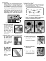
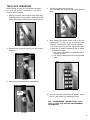
3. Install the lever with
proper orientation for the
lock/door hand used.
Tighten the set screw using a 1/8" hex wrench (see
Fig. 3).
IMPORTANT! The top of
the set screw must be at
(or below) lever surface. If
not, check to ensure the
lever is fully pushed toward the trim.
"anchor"
placed behind
"arm"
"arm"
Fig. 3: Tighten lever set screw
with 1/8" hex wrench
"anchor"
Fig. 2e: Pre-load the spring (LH shown) before installing.
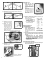
2f. Insert the pin through the
top of the new LH spring.
2g. Insert the pin/spring
through the retractor arm
hole while simultaneously
inserting the "anchor" end
of the spring into the
small hole in the cylinder/
adapter. See Fig. 2g.
Prepare the Door For
"Through-Bolting"
Fig. 2f: Insert pin into top of spring.
Pull the arm and hook its end onto the retractor arm.
Insert "anchor" end
into this hole.
the
n
3a. Install the Adams Rite® product as indicated by the
Adams Rite® door prep guidelines and instructions.
• If a new installation, the
face place must NOT be
installed at this time.
• If a retrofit installation,
remove the face plate.
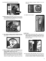
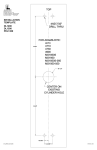
4. Place template (WI1459) as
shown. Important: Place the
template on top of existing cylinder hole and parallel to the
door edge.
Fig. 4: Template (WI1459)
through-bolt holes (circled)
4a. Drill completely through the door for through-bolting
the four mounting holes and battery cover access
bolt hole.
• IMPORTANT!--Drill the holes STRAIGHT
THROUGH the door, or the through-bolts will not
fit in the lock! THIS IS ESSENTIAL! Drill slowly
and STRAIGHT through the door.
• Reposition the template as often as needed until it
is placed correctly.
pu
ll a
rm
pin
Fig. 2g: Insert pin and spring; pull arm and clip on hook cam lever.
2h. Re-install the retaining ring
displayed in Fig. 2h.
Insert the Interface Cylinder
5. Loosen the set screw, then remove the outside cylinder (if present--See Fig. 5).
Old interface
cylinder
Set screw
Fig. 2h: Re-install retaining ring.
Finished configuration
shown at left (Fig. 2i).
Fig. 2i: Ready for LH operation.
4
Fig. 5: Loosen set screw before removing the
old interface cylinder (if present)