1
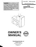
August 1979
FORM: OM-267A
Effective With Serial No. HJ199959
MODEL
G PS-bOO
G PS-1500
OWNERS
fullER
MANUAL
~
MILLER ELECTRIC MFG. CO.
718 S. BOUNDS ST. P.O. Box 1079
APPLETON, WI 54912 USA
ADDITIONAL COPY PRICE 55 CENTS
NWSA CODE NO. 4579
PRINTED
IN
U.S.A.
~\
.
t,
t~%
L&~
~
L
L~
LIMITED WARRANTY
EFFECTIVE: JUNE 1. 1979
This warranty supersedes all previous MILLER warranties and is ex
clusive with no other guarantees or warranties expressed or implied.
LIMITED
(
WARRANTY-Subject
to
the
terms
and conditions
hereof, Miller Electric Mfg. Co., Appleton, Wisconsin warrants
to its Distributor/Dealer that all new and unused Equipment
furnished by Miller is free from defect in workmanship and
material as of the time and place of delivery by Miller. No warranty is made by Miller with respect to engines, trade acother items manufactured by others. Such
cessories
or
engines, trade accessories and other items are sold sublect to
the warranties of their respective manufacturers, if any
All
engines are warranted by their manufacturer for one year from
date of original purchase,
.
Except
as
specified below, Millers warranty does
not
apply
components having normal useful life of less than one (1)
such as spot welder tips, relay and contactor points,
MILLERMATIC parts that come in contact with the welding
As
a
of general policy only, Miller may honor claims
by the original user within the foregoing periods.
matter
submitted
In the case of Millers breach of warranty or any other duty
with respect to the quality of any goods, the exclusive remedies
therefore shall be, at Millers option Ii) repair or (21 replacement
writing by Miller in appropriate cases, 13)
repair or replacement at an authorized
Miller service station or 14) payment of or credit for the purchase
price Iless reasonable depreciation based upon actual use) upon
return of the goods at Customers risk and expense. Upon receipt
of notice of apparent defect or failure, Miller shall instruct the claimant on the warranty claim procedures to be followed.
or, where authorized in
the reasonable cost of
~
to
year,
including
wire
not
nozzles and nozzle insulators where failure does
result from defect in
workmanship
or
material.
Miller shall be
required to honor warranty claims on warEquipment in the event of failure resulting from a defect
within the following periods from the date of delivery of Equipment to the original user:
ranted
ANY EXPRESS WARRANTY NOT PROVIDED HEREIN AND
WARRANTY, GUARANTY OR REPRESENTAPERFORMANCE, AND ANY REMEDY FOR
BREACH OF CONTRACT WHICH, BUT FOR THIS PROVISION,
MIGHT ARISE BY IMPLICATION, OPERATION OF LAW,
CUSTOM OF TRADE OR COURSE OF DEALING, INCLUDING
ANY IMPLIED
TION
ANY
AS
TO
IMPLIED WARRANTY OF MERCHANTABILITY OR OF
FITNESS FOR PARTICULAR PURPOSE, WITH RESPECT TO
ANY AND ALL EQUIPMENT FURNISHED BY MILLER IS EX
CLUDED AND DISCLAIMED BY MILLER.
1.
2.
Arc welders, power sources and components
Original main power rectifiers
Ilabor
3.
4.
..
1 year
only)
feeder/guns
-
5.
Replacement
Batteries
or
repair parts, exclusive of labor
EXCEPT
AS
90
.
days
1 year
60 days
6 months
EXPRESSLY
MILLER
WRITING,
All welding guns and
All other Millermatic Feeders
6.
1 year
3 years
ULTIMATE
PURCHASE
BY
EXPERIENCED
WELDING
IN
THE
EQUIPMENT
USE
AND
CONSUMER USE. MILLER
TO,
of the date of such failure.
MILLERS
,)-,
.r
ARE
BY
MILLER
INTENDED
IN
FOR
COMMERCIAL/INDUSTRIAL
USERS AND FOR OPERATION BY PERSONS TRAINED AND
provided that Miller is notified in writing within thirty 130) days
,~
PROVIDED
PRODUCTS
AND
NO
RESELLER
AND
MAINTENANCE
NOT FOR
CONSUMERS
OF
OR
WARRANTIES DO NOT EXTEND
IS
AUTHORIZED
WARRANTIES TO, ANY CONSUMER.
TO
EXTEND
?
TABLE OF CONTENTS
Page
Section No.
SECTION 1
1
1
-
-
1.
SAFETY RULES FOR OPERATION OF ARC WELDING POWER SOURCE
Introduction
2. General Precautions
1-3. ArcWelding
1 4. Standards Booklet Index
-
SECTION 2
2
3.
SECTION 3
3
4
5
Receiving-Handling
Description
2-4. Safety
-
1
1
INTRODUCTION
2-1. General
2- 2.
No.
5
5
5
INSTALLATION
3-1.
Location
6
3- 2.
Electrical Input Connections
6
3
-
3. Weld Output Connections
SECTION 4
4
4
-
-
1.
8
OPERATION
Power Control Switch
2. Overload Protection
8
9
4-3. Pilot Light
4-4. Meters
9
4-5.
9
SECTION 5
Duty Cycle
9
MAINTENANCE
5-1.
FanMotor
9
5- 2.
Internal
9
Cleaning
5- 3. Control Circuit Protection
SECTION 6
TROUBLESHOOTING
9
S
1-SAFETY RULES FOR OPERATION OF ARC
SECTION
1-1.
learn by experience. Learning safety through personal
experience, like a child touching a hot Stove (S harmful,
wasteful, and unwise. Let the experience of others teach you.
We
Metals coated with or containing materials that emit toxic
fumes should not be heated unless coating is removed from
the work surface, the area is well ventilated, or the operator
Safe practices developed from experience in the use of weld
ing and cutting are described in this manual. Research, devel
opment, and field experience have evolved reliable equipment
and safe installation, operation, and servicing practices. Acci
dents occur when equipment is improperly used or main
tained. The reason for the safe practices may not always be
given. Some are based on common sense, others may require
technical volumes to explain. It is wiser to follow the rules.
wears an
and, if
necessary, while
a
a
wearing
an
confined space should be avoided. Leaked gas
large quantities can change oxygen concentration danger
ously. Do not bring gas cylinders into a confined space.
Leaving confined
space, shut
OFF gas supply
at
source
to
prevent possible accumulation of gases in the space if down
stream valves have been accidently opened or left open.
Check
to
be
sure
that the space is safe before
re-entering it.
to
Vapors from chlorinated solvents
heat of the
and
These
-
-
Reference standards:
Published Standards
on
safety
are
Electrical Code, Occupational Safety and
Administration, local industrial codes, and local in
spection requirements also provide a basis for equipment in
stallation, use, and service.
National
Health
to form
can
be
decomposed by the
PHOSGENE.
a
highly
toxic
C.
Fire and
Explosion
Prevention
Causes of fire and explosion are: combustibles reached by the
arc, flame, flying sparks, hot slag or heated material; misuse
of compressed gases and cylinders; and short circuits.
BE AWARE THAT flying sparks or falling slag can pass
through cracks, along pipes, through windows or doors, and
through wall or floor openings, Out of sight of the goggled
operator. Sparks and slag can fly 35 feet.
GENERAL PRECAUTIONS
Burn Prevention
leather (or asbestos) gauntlet
protective clothing
gloves, hat, and high safety-toe shoes. Button shirt collar and
pocket flaps, and wear cuffless trousers to ~ioid entry of
sparks and slag.
Wear
(Or flame)
radiant energy can penetrate to atmospheres containing even
minute amounts of trichloroethylene or perchloroethylene.
also
available for additional and more complete procedures than
those given in this manual. They are listed in the Standards
Index in this manual. ANSI Z49.1 is the most complete.
arc
other
lung and eye irritating products. The ultra
gas,
violet (radiant) energy of the arc can also decompose tn
chloroethylene and perchloroethylene vapors to form phos
gene. DO NOT WELD or cut where solvent vapors can be
drawn into the welding or cutting atmosphere or where the
safe practices are divided into two Sections: 1
General Precautions, common to arc welding and cutting; and
2 Arc Welding (and Cutting)(only).
A.
being ventilated
air-supplied respirator.
confined space only while it is
Work
in
observe these safe practices may cause serious in.
jury or death. When safety becomes a habit, the equipment
can be used with confidence.
1-2.
air-supplied respirator.
in
Gas leaks in
Read and understand these safe practices before attempting
to install, operate, or service the equipment. Comply with
these procedures as applicable to the particular equipment
used and their instruction manuals, for personal safety and
for the safety of others.
The
POWER SOURCE~
harmful concentrations of toxic fumes. Adequate local
exhaust ventilation must be used, or each person in the area
as well as the operator must wear an air-supplied respirator.
For beryllium, both must be used.
INTRODUCTION
Failure
WELDING
-
To prevent fires and explosion:
Keep equipment clean and operable, free of oil, grease, and
(in electrical parts) of metallic particles that can cause short
circuits.
glasses with side shields
underneath, appropriate filter lenses or plates (protected by
clear cover glass). This is a MUST for welding or cutting, (and
chipping) to protect the eyes from radiant energy and flying
metal. Replace cover glass when broken, pitted, or spattered.
Wear helmet with safety
goggles
or
See 1-3A.2.
If combustibles are in area, do NOT weld or cut. Move the
work if practicable, to an area free of combustibles. Avoid
paint spray rooms, dip tanks, storage areas, ventilators. If the
cannot
Out
ignition
Avoid
oily
or
greasy
clothing.
A
spark
may
Hot metal such as electrode stubs and
never be handled without gloves.
Medical first aid and eye
ignite
be
of
shields.
them.
workpieces should
First aid facilities and
treatment.
moved, move combustibles at least 35 feet
reach of sparks and heat; or protect against
with suitable and snug-fitting, fire-resistant covers or
work
away
a
qualified first aid
person should be available for each shift
unless medical facilities are close by for immediate treatment
Walls touching combustibles on opposite sides should not be
welded on (or cut). Walls, ceilings, and floor near work
should be protected by heat-resistant covers or shields.
Fire watcher must be standing by
tinguishing equipment during and for
ing or cutting if:
with
some
suitable fire ex
time after weld
of flash burns of the eyes and skin burns.
appreciable combustibles (including building construc
tion) are within 35 feet
b. appreciable combustibles are further than 35 feet but can
be ignited by sparks
c.
openings (concealed or visible) in floors or walls within 35
a.
Ear plugs should be wom when working on overhead or in a
confined space. A hard hat should be worn when others work
overhead.
Flammable hair preparations should
to weld or cut.
not
feet may expose combustibles to sparks
be used by persons
d.
intending
combustibles
partitions
B.
Toxic Fume Prevention
with oxygen.
Lead
-,
cadmium
similar
-.
zinc
-,
adjacent to walls, ceilings, roofs, or metal
ignited by radiant orconducted heat.
be
Hot work permit should be
ensure
Adequate ventilation. Severe discomfort, illness or death can
result from fumes, vapors, heat, or oxygen enrichment or
depletion that welding (or cutting) may produce. Prevent
them with adequate ventilation as described in ANSI Stan
dard Z49.1 listed 1 in Standards index. NEVER ventilate
and
can
mercury
-,
materials, when welded
and
beryllium
-
bearing
(or cut) may produce
supervisors
obtained before operation to
approval that adequate precautions have
been taken.
After work is done, check that
embers, and flames.
area
is free of sparks,
glowing
An empty container that held combustibles, or that can pro.
duce flammable or toxic vapors when heated, must never be
welded on or cut, unless Container has first been Cleaned as
described in AWS Standard A6.O, listed 3 in Standards index.
OM-267 Page 1
thorough steam or caustic cleaning (or a
washing, depending on the combustibles
solubility) followed by purging and inerting with nitrogen or
carbon dioxide, and using protective equipment as recom
mended in A6.0. Waterfilling just below working level may
substitute for inerting.
includes:
This
solvent
a
water
or
unknown contents should be cleaned (see
Do NOT depend on sense of smell or sight
to determine if it is safe to weld or cut.
A container with
Protect cylinders particularly valves from bumps, falls,
objects, and
cylinders.
weather.
Replace
Stuck
Do NOT
use
valve.
cylinder valve that
supplier.
a
hammer
not be
can
falling
securely when moving
caps
or
wrench to open
opened by hand. Notify
a
your
paragraph above).
castings
cutting. They
Hollow
or
or
can
containers
must
be vented before
welding
gases. Never try to mix any gases in
Mixing
a
cylinder.
Never refill any cylinder.
explode.
Cylinder fittin~ should
Explosive atmospheres. Never weld or cut where the air may
contain flammable dust, gas, or liquid vapors (such as gaso
line).
3.
never
be modified
or
exchanged.
Hose
Prohibited
D.
use. Never use hose other than that designed for
the specified gas. A general hose identificatidn rule is: red for
fuel gas, green for oxygen, and black for inert gases.
Compressed Gas Equipment
Standard precautions. Comply with precautions in this
manual, and those detailed in CGA Standard P-i, PRECAU
TIONS FOR SAFE HANDLING OF COMPRESSED GASES
IN CYLINDERS, listed 6 in Standards index.
Pressure
1.
Use ferrules or clamps designed for the hose (not ordinary
or other substitute) as a binding to connect hoses to
wire
fittings.
No copper
Regulators
tubing splices. Use only
standard brass
fittings
to
splice hose.
relief valve is designed to protect Only the regula
from overpressure; it is not intended to protect any
downstream equipment. Provide such protection with one or
Regulator
tor
relief devices.
more
Never connect a regulator to a cylinder containing gas other
than that for which the regulator was designed.
Remove faulty regulator from service immediately for repair
(first close cylinder valve). The following symptoms indicate
a
Avoid long runs to prevent kinks and abuse. Suspend hose off
ground to keep it from being run over, stepped on, or other
wise damaged.
Coil
excess
hose to prevent kinks and
tangles.
Protect hose from damage by sharp
slag, and open flame.
edges,
and by
sparks,
Examine
faulty regulator:
tions.
Leaks if gas leaks externally.
Excessive Creep
if delivery pressure continues to rise with
downstream valve closed.
if gauge pointer does not move off stop pin
Faulty Gauge
when pressurized, nor returns to stop pin after pressure
release.
-
hose regularly for leaks, wear, and loose connec
Immerse pressured hose in water; bubbles indicate
teaks.
-
-
Repair. Do NOT attempt repair. Send faulty regulators for
repair to manufacturers
designated repair center, where
special techniques and tools are used by trained personnel.
2.
Cylinders
Cylinders must be handled carefully to prevent teaks and
damage to their walls, valves, or safety devices:
Avoid electrical Circuit contact with cylinders including third
rails, electrical wires, or welding circuits. They can produce
short circuit arcs that may lead to a serious accident. (See
Repair leaky
or
4.
hose by cutting
worn
(1-2D3). Do NOT
use
area Out
and
splicing
tape.
Proper Connections
Clean
cylinder valve outlet of impurities that may clog
orifices and damage seats before connecting regulator. Except
for hydrogen, crack valve momentarily, pointing outlet away
from people and sources of ignition. Wipe with a clean lintless cloth.
Match regulator to cylinder. Before connecting, check that
the regulator label and cylinder marking agree, and that the
regulator inlet and cylinder outlet match. NEVER CON
NECT a regulator designed for a particular gas or gases to a
cylindercontaining
any other gas.
1-3C.)
Tighten
DOT marking must be on each cylinder. It is
assurance of safety when the cylinder is properly handled.
ICC
or
an
Use only cylinders with name of gas
Identifying gas
marked on them; do not rely on color to identify gas con
tent. Notify supplier if unmarked. NEVER DEFACE or alter
connections. When
assembling threaded connections,
clean and smooth seats where necessary. Tighten. If connec
tion teaks, disassemble, clean, and retighten using properly
fitting wrench.
content.
name,
number,
or
other
markings
on
a
cylinder. It
is
illegal
Adapters. Use a CGA adapter (available from your supplier)
between cylinder and regulator, if one is required. Use two
wrenches to tighten adapter marked RIGHT and LEFT
and hazardous.
HAND threads.
Empties: Keep valves closed, replace caps securely;mark MT;
keep them separate from FULLS and return promptly.
Regulator outlet (or hose) connections may be identified by
right hand threads for oxygen and left hand threads (with
grooved hex on nut or shank) for fuel gas.
Prohibited use. Never use a cylinder or its
than its intended use, NEVER as a support
Locate
or
secure
Passageways
where
and
cylinders
work
so
areas.
they
contents
or
cannot be
Keep cylinders
for other
5.
roller.
knocked
over.
clear of areas
they may be struck.
Transporting cylinders. With a crane, use a secure support
as a platform or cradle. Do NOT lift cylinders off the
ground by their valves or caps, or by chains, Slings, or mag
such
nets.
Pressurizing Steps:
Drain regulator of residual gas through suitable vent before
opening cylinder (Or manifold valve) by turning adjusting
screw in (clockwise). Draining prevents excessive compression
heat at high pressure seat by allowing seat to open on pressur
ization. Leave adjusting screw engaged slightly on single-stage
regulators.
Stand to side of regulator while opening cylinder valve.
Open cylinder valve slowly so that regulator pressure in
slowly. When gauge is pressurized (gauge reaches regu
lator maximum) leave cylinder valve in following position:
For oxygen, and inert gases, open fully to seal stem against
possible leak. For fuel gas, open to less than one turn to
permit quick emergency shutoff.
creases
Do NOT expose cylinders to excessive heat, sparks, slag, and
etc. that may cause rupture. Do not allow contents to
exceed 130F.
Cool with water spray where such exposure
exists.
flame,
Page
2
operation with low-reflective, non-combustible screens or
panels. Allow for free air circulation, particularly at floor
Use pressure charts (available from your supplier) for safe
and efficient, recommended pressure settings on regulators.
level.
Check for leaks on first pressurization and regularly there
or
after. Brush with soap solution (capful of Ivory Liquid
equivalent per gallon of water). Bubbles indicate leak. Clean
off soapy water after test; dried soap is combustible.
E.
User
F.
Leaving Equipment Unattended
source
are
wearing flash
Before
B.
starting
are
in
area.
to
weld, make
Rope Staging-Support
with
precautions
be used for
welding
or
screen
flaps
or
bay
C.
Fire and
Explosion Prevention
Comply with precautions
Equipments
equipment.
Burn Protection
Protective
welding
rated capacity. Do not overload arc
It may overheat cables arid cause a fire.
or
flash and
cause a
Never strike an arc on a cylinder or other pressure vessel. It
brittle area that can cause a violent rupture or lead
to such a rupture later under rough handling.
creates a
D.
in 1-2.
Compressed
Gas
Equipment
Comply with precautions
The welding arc is intense and visibly bri~t. Its radiation can
damage eyes, penetrate lightwei~t clothing, reflect from
light-colored surfaces, and burn the skin end eyes. Skin burns
resemble acute sunburn, those from gas-shielded arcs are
GET BURNED; COMPLY
more severe and painful. DONT
WITH PRECAUTIONS.
in 1-2C.
Loose cable connections may overheat
fire.
standards referenced in index.
Comply with precautions
in 1-2B.
cut
Comply with precautions in 1-1, 1-2, and this section. Arc
Welding, properly done, is a safe process, but a careless opera
tor invites trouble. The equipment carries high currents at
significant voltages. The arc is very bright and hot. Sparks fly,
fumes rise, ultraviolet and infrared energy radiates, weld-
E.
in 1-2D.
Shock Prevention
Exposed hot conductors or other bare metal in the welding
circuit, or in ungrounded, electrically-HOT equipment can
fatally shock a person whose body becomes a conductor. DO
NOT STAND, SIT, LIE, LEAN ON, OR TOUCH a wet sur
face when welding, without suitable protection.
Clothing
To protect
Wear long-sleeve clothing (particularly for gas-shielded arc) in
addition to gloves, hat, and shoes (1-2A). As necessary, use
additional protective clothing such as leather jacket or
sleeves, flame-proof apron, and fire-resistant leggings. Avoid
outergarments of untreated cotton.
against shock:
Keep body and clothing dry. Never work in damp area with
out adequate insulation against electrical shock. Stay on a
dry duckboard, or rubber mat when dampness or sweat can
not be avoided. Sweat, sea water, or moisture between body
reduces
and an electrically HOT part
or grounded metal
the body surface electrical resistance, enabling dangerous and
possibly lethal currents to flow through the body.
-
Bare skin protection. Wear dark, substantial clothing. Button
collar to protect chest and neck and button pockets to pre
vent entry of sparks.
1.
2.
that
Generator engine exhaust must be vented to the outside air.
Carbon monoxide can kill.
ARC WELDING
1.
sure
closed.
Toxic Fume Prevention
Comply
meats are hot, and compressed gases may be used. The wise
operator avoids unnecessary risks and protects himself and
others from accidents. Precautions are described here and in
A.
See that all persons
doors
and drain gas.
Rope staging-support should not
ting operation; rope may burn.
1-3.
persons who
manual.
Close gas supply at
C.
all
Others working
goggles.
Responsibilities
Remove leaky or defective equipment from service immed
iately for repair. See User Responsibility statement in equip
ment
Viewing the weld. Provide face shields for
looking directly at the weld.
will be
Grounding
the
-
Equipment
Eye and Head Protection
installing, connect the frames of each unit such as
welding power source, control, work table, and water circula
tor to the building ground. Conductors must be adequate to
carry ground currents safely. Equipment made electrically
HOT by stray current may shock, possibly fatally. Do NOT
GROUND to electrical conduit, or to a pipe carrying ANY
gas or a flammable liquid such as oil or fuel.
When
Protect eyes from exposure
tric
arc
without
to arc.
NEVER look
at an elec
protection.
Welding helmet or shield containing a filter plate shade no.
12 or denser must be used when welding. Place over face
before striking arc.
Protect filter plate with
a
clear
cover
plate.
Three-phase connection. Check phase requirement of equip
before installing. If only 3-phase power is available,
connect single-phase equipment to only two wires of the
3-phase line. Do NOT connect the equipment ground lead to
the third (live) wire, or the equipment will become electri
a dangerous condition that can shock, possibly
cally HOT
fatally.
ment
Cracked
radiation
or
broken helmet
can
pass
through
or
shield should NOT be worn;
to cause burns.
Cracked, broken, or loose filter plates must be replaced IM
MEDIATELY. Replace clear cover plate when broken, pitted,
or spattered.
-
Before
side shields MUST be worn under the
helmet to give some protection to the eyes should the helmet
not be lowered over the face before an arc is struck. Looking
at an arc momentarily with unprotected eyes (particularly a
high intensity gas-shielded arc) can cause a retinal burn that
may leave a permanent dark area in the field of vision.
Flash
3.
goggles
with
Protection of Nearby Personnel
welding, check ground for continuity. Be sure conduc
touching bare metal of equipment frames at connec
tors are
tions.
line cord with a ground lead is provided with the equip
connection to a switchbox, connect the ground lead
to the grounded switchbox. If a three-prong plug is added for
connection to a grounded mating receptacle, the ground lead
must be connected to the ground prong only. If the line cord
If
a
ment for
with a three-prong plug, connect to a grounded mating
receptacle. Never remove the ground prong from a plug, or
use a plug with a broken off ground prong.
comes
Enclosed
room
or
For production welding, a separate
enclosed bay is best. In open areas, surround the
welding
area.
Trademark of Proctor & Gamble.
OM-267 Page 3
2.
Do
Electrode Holders
not
If,
in
open power circuit or change polarity while welding.
emergency, it must be disconnected, guard against
an
flash from switch
Fully insulated electrode holders should be used. Do NOT
holders with protruding screws.
shock burns,
3.
connect all power to
or
arcing.
use
Leaving equipment unattended. Always
equipment.
Connectors
Fully insulated lock-type
welding cable lengths.
connectors
should be used to
Power disconnect switch
join
power
1-4.
4.
must
shut OFF
be available
near
and dis
the welding
source.
STANDARDS BOOKLET INDEX
Cables
inspect cables for wear, cracks and damage.
IMMEDIATELY REPLACE those with excessively worn or
lethal shock from
damaged insulation to avoid possibly
bared cable. Cables with damaged areas may be taped to give
resistance equivalent to original cable.
Frequently
For
more
information,
their latest revisions and
refer to the
comply
as
following standards
applicable:
or
-
1.
ANSI Standard Z49.1, SAFETY IN WELDING AND
CUTTING obtainable from the American Welding
Society, 2501 NW 7th St., Miami, Fla. 33125.
2.
ANSI Standard Z87.1, SAFE PRACTICE FOR OCCUPA
TION AND EDUCATIONAL EYE AND FACE PROT~C
TION, obtainable from American National Standards
Institute, 1430 Broadway, New York, N.Y. 10018.
3.
American Welding Society Standard A6.0, WELDING
AND CUTTING CONTAINERS WHICH HAVE HELD
COMBUSTIBLES, obtainable same as item 1.
ELectrode wire becomes electrically HOT when the power
switch of gas metal-arc welding equipment is ON and welding
gun trigger is pressed. Keep hands and body clear of wire and
other HOT parts.
4.
Standard 51, OXYGEN-FUEL GAS SYSTEMS
FOR WELDING AND CUTTING, obtainable from the
Fire Protection Association, 470 Atlantic
National
Avenue, Boston, Mass. 02210.
7.
5.
NFPA Standard 518, CUTTING AND WELDING PRO
CESSES, obtainable same as item 4.
6.
CGA Pamphlet P-i. SAFE HANDLING OF COM
PRESSED GASES IN CYLINDERS, obtain~Ie from the
Compressed Gas Association, 500 Fifth Avenue, New
York, N. V. 10036.
7.
OSHA Standard 29 CFR, Part 1910, Subpart 0, WELD
ING, CUTTING AND BRAZING.
Keep cable dry, free of oil and grease, and protected from
hot metal and sparks.
Terminals And Other Exposed Parts
5.
Terminals and other exposed parts of electrical units should
have insulating covers secured before operation.
Electrode Wire
6.
Safety Devices
Safety devices such
not
be disconnected
as
or
interlocks and circuit breakers should
shunted out.
Before installation, inspection, or service, of equipment, shut
OFF all power and remove line fuses (or lock or red-t~
switches) to prevent accidental turning ON of power. Discon
nect all cables from welding power source, and pull all 115
volts line-cord pIu~.
Page
4
NFPA
SECTION 2- INTRODUCTION
Input At Rated
Rated
Model
1000
1500
Welding
Current Amperes
100% Duty Cycle
1000@76 Volts
1500@76Volts
60 Hz. Three-Phase
Open-
Weight
Amperes At
Circuit
Voltage
Output
Load
Max.
230 Volts
85
224
330
85
(Pounds)
Dimensions
kva
f460_Volts
kw
(Inches)
Net
Height-41-1(8
112
85
89
Width -27-1/4
896
Width
-27-1/4
986
t
Height-41-1/8
123
131
I
I
Depth -46
165
I Ship
t
106811158
Depth -46
Figure 2-1. Specifications
TB-080 172
Figure
2-1.
2-2. Functional
This will
help avoid possible iniury
welding applications.
GENERAL
This manual has been prepared especially for use in familiar
izing personnel with the design, installation, operation, main
tenance, and troubleshooting of this equipment. All informa
tion presented herein should be given careful consideration to
assure optimum performance of this equipment.
2-2.
Diagram
due to misuse
or
improper
The
following definitions apply to CAUTION. IMPORTANT,
and NOTE blocks found throughout this manual:
RECEIVING-HANDLING
Prior to installing this equipment, clean all packing material
from around the unit and carefully inspect for any damage
that may have occurred during shipment. Any claims for loss
or damage that may have occurred in transit must be filed by
the purchaser with the carrier. A copy of the bill of lading
and freight bill will be furnished by the carrier on request if
occasion to file claim arises.
When requesting information concerning this equipment, it is
essential that Model Description and/or Stock Number and
Serial (or Style) Numbers of the equipment be supplied.
I
Under this
heading, installation, ope rating, and main
procedures or practices will be found that if
carefully followed may create a hazard to per
tenance
not
.
sonnel.
1~A~1
U
Under
this
heading, installation, operating, and main
procedures or practices will be found that if
carefully followed may result in damage to equip
tenance
2-3.
DESCRIPTION
This
incorporates a three phase Delta
(CP) type main power
connected, constant potential
transformer to provide the constant voltage output required
to operate the resistance grid welding stations connected to
welding
power source
not
I
SAFETY
Before the equipment is put into operation, the safety sec
tion at the front of this manual should be read completely.
I
m
the unit.
2-4.
ment.
I
I
Under this heading, explanatory statements will be
found that need special emphasis to obtain the most
efficient operation of the equipment.
I
OM-267 Page 5
SECTION 3
-
INSTALLATION
ELECTRICAL INPUT CONNECTIONS
3-2.
Electrical Input Requirements
A.
welding power source is designed to be operated from a
three-phase, 60 Hertz, ac power supply which has a line volt
age rating that corresponds with one of the electrical input
voltages shown on the nameplate. Consult the local electric
utility if there is any question about the type of electrical
This
system available at the installation site or how proper
tions to the welding power source are to be made.
connec
Input Conductor Connections
B.
m
It
is
recommended
that
a
line disconnect switch be
input circuit to the welding power
This would provide a safe and convenient
source.
means to completely remove all electrical power from
the welding power source whenever it isnecessary to
perform any internal function on the unit
installed
lncludlng 2-7/8
in
the
Uftlng Eye
CAUTION
TB-079 823
Figure 3-1. Overall Dimensions And
Hole Layout
3-1.
LOCATION
Base
Mounting
making electrical input connections to the
lockout
welding power source, machinery
procedures should be employed. If the connection is
to be made from a line disconnect switch, the switch
should be padlocked in the open position. If the
(Figure 3-1)
connection is made from a fuse box, remove the fuses
from the box and padlock the cover in the closed
position. If the unit is connected to a circuit breaker,
A proper installation site should be selected for the welding
power source if the unit is to provide dependable service, and
remain relatively maintenance free.
other disconnecting device without locking
facilities, attach a red tag to the device to warn others
that the circuit is being worked on.
or
A proper installation site permits freedom of air movement
into and out of the welding power source, and also least
subjects the unit to dust, dirt, moisture, and corrosive vapors.
A minimum of 18 inches of unrestricted space must be main
tained
between
the
source front and rear
Also,the underside of the
be
welding power
kept completely free of
obstructions. The installation site should also permit easy
removal of the welding power source Outer enclosure for
maintenance functions.
panels and the
welding
power
CAUTION
nearest obstruction.
source
must
~ct
source
power
IMPORTANT
place any filtering device over the intake air
passeges of the welding power source as this would
restrict the volume of intake air and thereby subject
the welding power source internal components to an
to
the
welding
power
Supply.
Table 3-1.
condition and subsequent failure. War
ranty is void if any type of filtering device is used
overheating
base for
dimensions and
input conductors
The input conductors should be covered with an insulating
material which conforms to local electrical standards. Table
3-1 is provided only as a guide for selecting the proper size
input conductors and fuses.
Do not
Holes are provided in the welding power
mounting purposes. FIgure 3-1 gIves overall
the base mounting hole layout.
the
before making connections to the three.phase
Input Conductor and Fuse Size
Input Conductor Size- AWG
source
Model
11000
460 Volts
575 Volts
230 Volts
460 Volts
4/0 (2)
2 (8)
4 (8)
350
115
125
400 MCM (1/0)
2/0 (4)
1/0 (6)
500
250
225
Ampere
j~OO Ampere
Fuse Size In Amperes
230 Volts
575 Volts
On
for
most welding power sources a lifting device is provided
moving the unit. However, if a fork lift vehicle is used for
lifting the unit, be sure that the lift forks are long enough to
extend completely under the base.
.fl~TA~
The
use
of lift forks too short to extend out of the
opposite side of the base will expose internal com
ponents to damage should the tips of the lift forks
penetrate the bottom of the unit.
Page 6
lnput conductor sizes are based on allowable ampacities of
insulated copper conductors, having a temperature rating of
75C, with not more than three conductors in a raceway or
cable. Numbers in ( ) are equipment ground conductor sizes.
Insert the three input conductors plus one ground conductor
the access hole on the rear panel. This hole will
accept standard conduit fittings. See Figure 3-2 for hole loca
through
tion and size.
230 VOLTS
It is recommended that a terminal lug of adequate
amperage capacity be attached to the ends of the in
put and ground conductors. The hole diameter in the
terminal lug must be of proper size
the line and ground terminal studs.
to
U
accommodate
.
Connect the three input conductors to the line terminals on
the contactor. Connect the ground conductor to the terminal
labeled GROUND on the frame near the contactor. The
460 VOLTS
~0I
16
01
10
0IF~6I
10
l0
o
o
01
O
10
01
10
61
tO
61
0
0
~1
remaining end of the ground conductor should be connected
a
proper ground. Use a grounding method that is
acceptable to the local electrical inspection authority.
to
059 530
Figure 3-3. Input Voltage Jumper Link Arrangement
~ou nd
power
source
on!y. Do
terminal is
chassis and
not connect
C.
connec ted
to the we Iding
grounding purposes
conductor from the ground
a
is
terminal to any one of the line terminals as this will
result in an electrically energized welding power
source
chassis.
Matching The Welding Power Source To The Avail
Voltage
able Input
for
The input voltage jumper links provided on the primary ter
minal board permit the welding power source to be operated
from various line voltages. The various voltages from which
this unit may be operated are stated on the nameplate and on
.
the input voltage label. The input voltage jumper links are
positioned for the highest of the voltages stated on the
nameplate. If the welding power source is to be operated
from a line voltage which is lower than the highest voltage for
which the unit was designed, the jumper links will have to be
moved to the proper positions before operating the unit.
Figure 3-3 shows the various positions of the jumper links on
the standard welding power source. If the input voltages on
the nameplate differ from those shown in Figure 3-3, the
input voltage jumper links must be positioned as shown on
the input voltage label.
NOTE
If only one jumper link is required on each of the
grouped terminals, it is recommended that the unused
jumper links be placed across the terminals which are
to be used. This will prevent losing the jumper links
which are not required for this connection.
TB-079 825
Figure 3-2. Input Conductor Connections
Table 3-2.
Welding
Total
Amperes, DC
50
Welding Cable
Lengt h
100
150
Size
Of Cable I Copper) In W eld Circuit
200
250
300
350
400
100
4
4
2
2
2
1
1/0
1/0
150
2
2
2
1
1/0
2/0
3/b
3/0
200
1
1
1
1/0
2/0
3/0
4/0
4/0
2-2/0
2-3/0
2-2/0
250
1/0
1/0
1/0
2/0
3/0
4/0
300
2/0
2/0
2/0
3/0
4/0
2-2/0
350
3/0
3/0
4/0
400
3/0
3/0
3/0
500
4/0
4/0
3/0
4/0
4/0
2-2/0
2-2/0
2-2/0
2-3/0
2-3/0
2-3/0
24/0
600
4/0
4/0
2-2/0
2-3/0
700
4/0
4/0
2-3/0
800
2-2/0
2-2/0
900
2-3/0
2-3/0
2-3/0
2-3/0
2-4/0
2-4/0
2-4/0
500MCM
2-3/0
2-4/0
1000
1250
2-4/0
2-4/0
2-4/0
500MCM
2-3/0
2-4/0
2-4/0
1000MCM
500MCM
1000MCM
1000MCM
500MCM
1000MCM
1000MCM
1000MCM
I000MCM
I000MCM
1000MCM
1000MCM
1000MCM
1000MCM
1000MCM
1000MCM
1000MCM
1000MCM
1000MCM
1000MCM
1000MCM
500MCM
1000MCM
1000MCM
1500
500MCM
500MCM
1000MCM
1000MCM
1000MCM
1750
1000MCM
1000MCM
1000MCM
1000MCM
2000
1000MCM
1000MCM
1000MCM
2-4/0
2-3/0
TA-052 764
NOTE:
A.
50 FEET OR LESS.
B.
CABLE SIZE IS BASED ON DIRECT CURRENT (DC), 100% DUTY CYCLE AND EITHER A
4 VOLTS OR LESS DROP OR A CURRENT DENSITY OF NOT OVER 300 CIRCULAR MILS
PER AMP.
C.
WELD CABLE
INSULATION WITH A VOLTAGE RATING TO WITHSTAND THE OPENCIRCUIT VOLTAGE (OCV) OF THE WELDING POWER SOURCE MUST BE USED. WHILE
MOST WELDING POWER SOURCES HAVE AN OPEN-CIRCUIT VOLTAGE OF LESS THAN
100 VOLTS, SOME WELDING POWER SOURCES OF SPECIAL DESIGN MAY HAVE HIGH
ER OPEN-CIRCUIT VOLTAGE.
OM-267 Page 7
3-3.
WELD OUTPUT CONNECTIONS
(Figure 3-4)
To obtain the full rated output from this unit, it is necessary
select, install, and maintain proper welding cables. Failure
in any of these areas may result in loss than
to comply
'
'
'
'
'
'
'
'
A
B
A
B
'~ ~
~l
to
satisfactory welding performance.
DC Nog~ti~e
DC Po~iti~a
DC Nog~tivo
DC Positive
B
A
A
079 746
1000 Ampere Models
-
B
1000 AMP POSITION
500 AMP POSITION
U
Ensure that the unit is completely shut down before
making any weld output connections.
DC
DC Positive
'
'
DC Positive
Negative
'
'
oc
Negative
'
'
__
A.
Location
The POSITIVE and NEGATIVE weld output terminals
located on the lower portion of the front panel.
B.
are
'
'
'
'
'
'
'
'
A
B
A
B
A
B
A
B
750 AMP POSITION
Welding Cables
were
not
followed
ordered with this unit, the steps
to
the best welding
ensure
is
C.
recommended
that
and
condition
2.
Use Table 3-2
the
of
as a
anticipated
great extent dependent on the use
and connections that are in good
adequate size.
to a
guide for selecting
maximum
weld
Output Connections
Simultaneously, 500 amperes of weld output is available
between one B Positive and B Negative output terminals of
the 1000 ampere models. 750 amperes of weld output is
available from the 1500 ampere models when similiar
connections are made. When the weld output terminals are
bused together, 1000 amperes of weld output is available
between the A Positive and A Negative or B Positive and B
Negative output terminals of the 1000 amperes models.
1500 amperes of weld output is available from the 1500
ampere models when similiar connections are made. These
units are shipped with the bus bar in place.
which is added to the voltage of the arc. Excessive cable
resistance may result in overloading as well as reducing
the maximum current output capability of this Unit.
Prªper operation is
welding cables
Weld
Output Connections
When the weld output terminals are not bused together. 500
amperes of weld output is available between one A Positive
and A Negative output terminals of the 1000 ampere models.
the
welding cables be kept as
short as possible, be placed close together, and be of
adequate current carrying capacity. The resistance of the
welding cables and connections causes a voltage drop
of
Weld
Figure 3-4.
performau~ce:
It
059 539
1500 Ampere Models
if welding cables
listed should be
1.
1500 AMP POSITION
cable size for
which will be
from the welding
correct
current
used, Table 3-2 shows total cable length
power source to the resistance grid welding station. Select
the size cable that is recommended for the maximum
weld current that is to be used.
3.
Do not
4.
Use correct Iugs on the weld cables to connect them to
the weld output terminals.
5.
Ensure that all connections
use
damaged
or
frayed cables.
~05 it ive
tput te rm inal of one sect ion of th is
connected to the negative output
terminal of the other section, two times the normal
output voltage will exist between the remaining two
terminals, Consult applicable safety codes.
power
are
clean and
source
ou
is
~output
tight,
SECTION 4
-
OPERATION
4-1.
POWER CONTROL SWITCH
(Figure 4-1)
Ammeter B
B
Voltmeter
~ssing
not
the POWER CONTROL STOP button does
power from all of the welding power
internal circuitry. Completely terminate all
remove
source
electrical
to
the welding power source by
power
lockout procedures
before
employing machinery
attempting any inspection or work on the inside of the
unit. If the welding power source is connected to a
disconnect switch, padlock the switch in an open
position. If connected to a fuse box, remove the fuses
and padlock the cover in the closed position. If the
unit is connected to a circuit breaker, or other
disconnecting device without locking facilities, attach
a
is
red tag to the device to
being worked on.
Depressing
DC Positive
DC Negative
TB-079 824
Figure
Page 8
4-1. Front Panel
the
POWER
warn
others that the circuit
CONTROL
START
button
will
energize the welding power source and place the unit in a
ready-to-weld status. The START button must be held in
momentarily to ensure that the fan is running at operating
speed. Depressing the POWER CONTROL STOP button will
shut the welding power source down.
4-2.
OVERLOAD PROTECTION
Thermostat TP1, located in the main transformer, is wired
into the contactor W coil circuit. Should overheating occur,
TP1 would open causing the contactor to drop out thereby
suspending all operations. If TP1 opens, allow the unit to
cool before resuming operations.
Circuit breaker CB protects the welding power source from
excessive secondary current draw. Current transformer CT1
and CT2, located in the secondary of the main transformer,
sense the secondary current draw. Should overloading occur,
CB would open causing the contactor to drop Out thereby
suspending all operations.
2000
MODEL
1500
GPS-1500
U
UI
<
0
z
0
-J
UI
GPS -10 00
1000
To place the welding power source in a ready-to-weld status
should this circuit breaker trip, the circuit breaker should be
manually reset. Should the circuit breaker continue to trip
after each reset, an internal problem in the circuitry is most
probably present. Do not attempt any further welding until
the trouble has been remedied.
40
4-4.
welding
70
80
90 100
B.079 809
Figure
4-2.
Duty Cycle
Chart
DUTY CYCLE
The duty cycle of a welding power source is the percentage
of a ten minute period that a welding power source can safely
be operated at a given output. This welding power source is
rated at 100 percent duty cycle. This means that the welding
power source can be safely operated at rated load contin
uously. Figure 4-2 enables the operator to determine the safe
output of the welding power source at various duty cycles.
PILOT LIGHT
The pilot light PL1 indicates when the
is in a ready-to-weld status.
60
% DUTY CYCLE
4-5:
4-3.
50
power source
METERS
The meters
They
are
are
provided
intended for
not
to
monitor the
I
welding operation.
exact current or
voltage
IMPORTANT
measure
These meters are internally connected to the output
terminals. The voltmeters will indicate the voltage at the
output terminals, but not necessarily the actual voltage at the
welding arc (due to cable resistance, poor connections, etc.).
The ammeters will indicate the current output of the unit.
ments.
Exceeding
the
heating and
indicated
duty cycle
thereby damage
to
will cause
over-
the welding power
source.
SECTION 5- MAINTENANCE
factured with lifetime-lubricated sealed ball bearings and
I
attention should be
5-2.
the POWER CONTROL STOP button does
remove
power from all of the welding power
no
required.
INTERNAL CLEANING
Depressing
not
internal circuitry.
electrical power to the
source
Completely
terminate
Occasional blowing out or vacuuming of the dust and dirt
from around the internal components is recommended. This
should be done periodically depending upon the location of
the unit and the amount of dust and dirt in the atmosphere.
The welding power source outer enclosure should be removed
and a clean, dry air stream or vacuum suction should be used
for this cleaning operation.
all
welding power source by
lockout procedures
before
machinery
attempting any inspection or work on the inside of the
unit. If the welding power source is connected to a
disconnect switch, padlock the switch in an open
position. If connected to a fuse box, remove the fuses
and padlock the cover in the closed position. If the
unit is connected to a circuit breaker, or other
disconnecting device without locking facilities, attach
employing
a
red tag to the device to
worked on.
warn
5-3.
The entire control circuit of the welding power source is
protected by a 600 volt, 3 ampere, cartridge type fuse Fl.
This fuse is located under the top cover beside contactor W.
Should this fuse open, the welding power source would
completely shut down.
others that the circuit
~~ing
5-1.
CONTROL CIRCUIT PROTECTION
FAN MOTOR
All models are equipped with an exhaust fan and rely on
forced draft for adequate cooling. The fan motor is manu
SECTION 6
U
I-
-
TROUBLESHOOTING
volta~
Hazardous
the
internal
on
present
circuitry of the welding power source as long as power
is connected to the unit. Disconnect power before
attempting any inspection or work on the inside of the
unit. Troubleshooting of internal circuitry should be
performed by qualified personnel only.
The
following
remedies for
welding
power
is designed to diagnose and provide
of the troubles that may develop in this
chart
some
It
is
proper installation has been made,
3 of this manual, and that the welding
has been functioning properly until this trouble
assumed
according
that
to Section
power source
developed.
Use this chart in conjunction with the circuit diagram while
performing troubleshooting procedures. If the trouble is not
remedied after performing these procedures, the nearest
Factory Authorized Service Station should be contacted. In
all
of equipment malfunction, the manufacturers
cases
recommendations should be strictly followed.
source.
OM-267 Page 9
TROUBLE
PROBABLE CAUSE
No output.
Thermostat TP1 open.
REMEDY
Allow unit
a
cooling period.
Replace defective TP1.
.
Fan
motor
switch FMS is open.
Hold START button in momentarily.
Fan motor rpm is too slow due to low input
Replace defective fan
voltage.
motor FM.
Replace defective FMS.
Circuit breaker CB open.
Reset CB.
Replace defective CB.
Fuse Fl is blown.
1f it becomes necessary
to
replace
any fuse in the
welding
Replace defective Fl.
power source,
ensure
that
a
fuse of the proper size is used.
Circuit
Figure 6-1. Circuit Diagram For 1000 Ampere Models
Page
10
Diagram No. B-080
675
POSITIVE
Circuit
Diagram
No. CB-902 388-lA
Figure 6-2. Circuit Diagram For 1500 Ampere Models
OM-267 Page 11
August1979
FORM: OM-267A
Effective With Serial No~ HJ199959
MODEL
GPS-1000
GPS-1500
PARTS
LIST
13
Figure A
OM-267 Page 1
Left Side View
Quantity
Item
No.
Dia.
Mkgs
Figure
1
059572
059592
4
W
4
W
Wi
036630
059720
*079 507
079506
004104
*004258
004259
034821
*6()4259
5
6
Fl
7
SR1,11
VS 1,2
D1-6,
079827
024 471
11-16
037 157
Cl -6
11-16
031 689
SR1,11
059 685
7
1000 1500
Description
Left Side View
2
T2
________
Part No.
A
3
Model
Factory
012638
COVER, opening exit cable
PANEL, rear
TRANSFORMER, control 100VA 115-230/460
CONTACTOR, 120 amp 3 pole 600 volts (consisting of)
KIT, contact point
COIL, contactor 120/240 volts
CONTACTOR, 210 amp 3 pole 600 volts w/ 115 volts ac (consisting of)
KIT, contact point
COIL, contactor 120 volts ac
INTERLOCK, contactor normally open
FUSE, cartridge 3 amp 600 volts
HOLDER, fuse cartridge 30 amp 600 volts
RECTIFIER, silicon diode (consisting of)
SUPPRESSOR, 1 uf 2.7 ohm
-
-
-
.
.
DIODE, rectifier 275
amp 250 volts
straight polarity
1
1
1
1
1
1
1
1
1
1
1
1
1
1
1
1
1
1
2
1
12
CAPACITOR, ceramic0.01 uf500voltsdcw/3/16&1/4terminals
6
RECTIFIER, silicon diode (consisting of)
2
Cl -6
11-16
031 689
.
CAPACITOR, ceramic 0.01 uf 500 volts dc w/3/16 & 1/4 terminals
6
Dl -6
11-16
8
9
9
10
11
12
Vl,2
A1,2
Al,2
PB1
PL1
CB
13
15
16
DIODE, rectifier 275 amp 250 volts straight polarity
METER, volt dc 0-100 scale
METER, amp dc 5OMV 0-800 scale
METER, amp dc 5OMV 0.1K scale
SWITCH, push button start stop 60 amp 110 volts
BULB, incandescant slide base 120 volts
2
2
-
HOUSING, light
-
slide base 125 volts
LENS, light
034945
CIRCUIT BREAKER, manual reset 2P 5 amp 240 volts
BAFFLE, air top rectifier
red clear
-
ac
-
059616 BRACKET, mounting terminal board
079388 SHUNT, meter5oMV800amp
030635 SHUNT, meter 5OMV 1000 amp
059567 TERMINAL ASSEMBLY, power output
601841
NUT, brass-hexjam 5/8-11
601842
NUT, brass hex full 5/8-11
059566
TERMINAL BOARD, power output
038909 .STUD,brass5/8-11 x3
602249
WASHER, flat steel SAE 5/8
602219
WASHER, lock steel external tooth
038032
BUS BAR
059983 BUS BAR, jumper secondary
-
Shunt
Shunt
-
18
2
2
-
027 628
059563
14
15
037 157
025638
059118
059 120
011 636
*027 629
027 631
1
1
1
1
1
1
1
1
1
1
1
1
1
1
2
2
(consisting of)
-
-
-
-
-
1
16
8
2
8
1
16
82
8
8
8
8
4
4
8
2
*Recommended Spare Parts.
BE SURE TO PROVIDE MODEL AND SERIAL NUMBERS WHEN ORDERING REPLACEMENT PARTS.
OM-267
Page
2
-31
~1
1
Figure
Page3
B
Right Side View
Quantity
Item
Dia.
Factory
No.
Mkgs.
Part No.
Figure
28
R1,11
R2,12
SR2,12
C8,18
C7,17
29
TEl
TE2
30
31
32
FM
FMS
33
34
Ti
34
Ti
35
35
CT1,2
CT1,2
TP1
**Replace
Right Side
B
27
at
Model
Description
009139
059 605
030 691
604288
037 513
031 640
601 375
031 683
059 555
038 897
602 221
010 910
601837
038 621
038804
038 898
038 620
059585
014 425
032616
032 633
011 850
052 613
059676
079 718
059 575
**079 719
**059 576
**079 529
059 574
080075
036612
026 181
059 559
003 107
010014
026 627
Factory
or
100011500
View
VISOR,front-top
1
1
PANEL, front
1
1
RESISTOR, carbon
2
1 watt4700 ohm
RESISTOR,WWfixedl0watt2ohm
RECTIFIER, selenium control
CAPACITOR, electrolytic 500 uf 200 volts dc
RING, mounting capacitor
CAPACITOR, paperoiiO.5uf200voltsdc
TERMINAL ASSEMBLY, primary (consisting of)
TERMINAL BOARD, primary
WASHER, lock steel internal tooth 3/8
WASHER, flat steel SAE 3/8
.NUT,brass-hex3/8-16
BLOCK, terminal 30 amp 4 pole
.STUD,brass3/8-16x2-1/2
LINK, terminal connecting
LINK, jumper terminal block 30 amp
WINDTUNNEL,20inch
BAR, support windtunnel
BLADE,fan60Hz20inch3wing2l degree
MOTOR, 1/4 hp 230 volts ac 1625 RPM (consisting of)
SWITCH, centrifugal (GE Motor) or
SWITCH, starting (Emerson Motor)
2
2
2
2
-
.
-
.
-
.
.
-
.
-
.
-
.
.
BASE
.
1
1
1
12
12
12
12
36
36
1
1
12
12
6
1
6
1
1
1
2
2
1
1
1
1
1
1
1
1
1
1
(consisting of)
1
main (consisting of)
TRANSFORMER SUBASSEMBLY
TRANSFORMER SUBASSEMBLY
1
TRANSFORMER,
TRANSFORMER,
.
2
1
power
power
-
main
1
-
COIL, primary/secondary
COIL, primary/secondary
TRANSFORMER, current300/5
TRANSFORMER,current800/5
THERMOSTAT, normally closed (located in coils)
PANEL, side
COVER, top
.
1
6
6
.
2
2
6
2
1
CLAMP
GASKET, lifting eye
6
2
1
2
-
cover
1
1
Factory Authorized Service Station.
BE SURE TO PROVIDE MODEL AND SERIAL NUMBERS WHEN ORDERING REPLACEMENT PARTS.
OM-267 Page 4