1
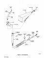
July1988
FORM:
Effective With
Style
No. JA-9
_...
MIIIe
OWNERS
IMPORTANT
MODEL
GA-5OGL
MANUAL
Read and understand the entire contents of both this
manual and the power source manual used with this
unit, with special
the safety material throughout both manuals, before in-
emphasis on
stalling, operating,
maintaining this equipment. This unit and these
only by persons trained and experienced in the
safe operation of welding equipment. Do not allow untrained persons to
instructions
are
install, operate,
not
or
for
or
use
Miller Electric Mfg. Co.
AM~G,o~LIa Cornp~n~
~o. Box 1079
Appleton,
WI 54912 USA
Tel. 414-734-9821
maintain this unit. Contact your distributor if you do
fully understand these instructions.
PRINTED IN U.S.A.
ADDITIONAL-COPY PRICE 25 CENTS
M-1532A
.-
~-~-~
-\~-~1-~,mp-~
LIMITED WARRANTY
EFFECTIVE: FEBRUARY 18, 1988
supersedes
This warranty
all previous MILLER warranties and
LIMITED WARRANTY
-
Subject
to the terms and
is
exclusive with
or, where authorized in
Equipment furnished by Miller is free from defect in workmanship and material as of the time and place of delivery by Miller.
No warranty is made by Miller with respect to engines, trade
accessories or other items manufactured by others. Such
engines, trade accessories and other items are sold subject to
the warranties of their respective manufacturers, if any
All
engines are warranted by their manufacturer for one year from
date of original purchase, except Tecumseh engines which
.
or
warranties
expressed
or
implied.
the reasonable cost of
writing by Miller in appropriate cases, (3)
repair or replacement at an authorized
Miller service station
(4) payment of
or
or
credit for the purchase
price (less reasonable depreciation based upon actual use) upon
risk and expense. MILLERs
return of the goods at Customers
option of repair or replacement will be F.O.B., Factory, at
Appleton, Wisconsin, or FOB., at a MILLER authorized service
facility, therefore, no compensation for transportation costs of
any kind will be allowed. Upon receipt of notice of apparent
defect or failure, Miller shall instruct the claimant on the warranty
claim procedures to be followed.
.
a two
other guarantees
In the case of Millers breach of warranty or any other duty
with respect to the quality of any goods, the exclusive remedies
therefore shall be, at Millers option (1) repair or (2) replacement
condi-
tions hereof, Miller Electric Mfg. Co., Appleton, Wisconsin
warrants to its Distributor/Dealer that all new and unused
have
no
year warranty,
~
as specified below, Millers warranty does not apply
components having normal useful life of less than one (1)
year, such as spot welder tips, relay and contactor points,
MILLERMATIC parts that come in contact with the welding
wire including nozzles and nozzle insulators where failure does
not result from defect in workmanship or material.
to
~/
~
~
~
~
ANY EXPRESS WARRANTY NOT PROVIDED HEREIN AND
ANY IMPLIED WARRANTY, GUARANTY OR REPRESENTA
T1ON AS TO PERFORMANCE, AND ANY REMEDY FOR
BREACH OF CONTRACT WHICH, BUT FOR THIS PROViSION,
MIGHT ARISE BY IMPLICATION, OPERATION OF LAW,
Miller shall be
required to honor warranty claims on warEquipment in the event of failure resulting from a defect
within the following periods from the date of delivery of Equipment to the original user:
CUSTOM OF TRADE OR COURSE OF DEAUNG, INCLUDING
ranted
ANY IMPUED WARRANTY OF MERCHANTABIUTY OR OF
FITNESS FOR PARTICULAR PURPOSE, WITH RESPECT TO
ANY AND ALL EQUIPMENT FURNISHED BY MILLER IS EX
j~
1. Arc welders, p~r sour~, robots, and componente
2. Load banks
3.
Original
(labor
4. All
6.
rr~
7.
N
q~J
(1
main power rectifiers
1 year only)
guns, feeder/guns and torches
5. All other Millermatic Feeders
Ł~
~
~J
-
welding
Replacement
or
CLUDED AND DISCLAIMED BY MILLER.
1 year
1 year
3 years
EXCEPT
.....
repair parts, exclusive of labor
Batteries
.
1 year
60 days
6 months
..
of the date of such failure.
As
a
MILLER
CONSUMER USE. MILLERS WARRANTIES DO NOT EXTEND
AND NO RESELLER IS AUTHORIZED TO EXTEND
MILLERS WARRANTIES TO, ANY CONSUMER.
provided that Miller is notified in writing within thirty (30) days
TO,
matter of
submitted
AS
EXPRESSLY PROVIDED BY MILLER IN
ARE
INTENDED
FOR
PRODUCTS
ULTIMATE PURCHASE BY COMMERCIAL/INDUSTRIAL
USERS AND FOR OPERATION BY PERSONS TRAINED AND
IN
EXPERIENCED
THE
USE AND
MAINTENANCE OF
WELDING EQUIPMENT AND NOT FOR CONSUMERS OR
WRITING,
90 days
general policy only, Miller may honor claims
by the original user within the foregoing periods.
.
-...
.....
.....
April 27, 1990
ERRATA SHEET
_____________________
After this manual was
to data
FORM: OM-1532A
printed, refinements
appearing later In this manual.
In
equipment design occurred.
This sheet lists
exceptions
AMENDMENT TO PARTS LIST
Amend Parts List
as
follows:
All Parts Eff w/KA27
Part
No.
Replaced
7-5
7-13
7-17
7-18
7-26
008 931
602 177
Deleted
602 178
856
852
624
134 601
134 600
114 974
7-26
079
079
009
009
625
114973
**
Descnption
With
Quantit:
-
**First
digit represents page
no
-
SCREW, set sti sch .250-20 x .375
SLEEVE, centering monocoil
GUIDE, wire outlet 1/1 6-5/64
LINER, monocoil 1/16-5/64 wire x lift 6in
LINER, monocoil i/16-5/64wirex l6ft8in
digits following
dash represent item
no.
BE SURE TO PROVIDE MODEL AND SERIAL NUMBER WHEN ORDERING REPLACEMENT PARTS.
1
1
1
1
1
SECTION 1
Rating: 100%
Duty Cycle, dcrp
500
Amperes
Wire
Diameter
1/16 thru 1/8 in.
thru 3.2 mm)
(1.6
A.
Cable
Cooling
Length
Method
lOft. 3.0
15 ft. 4.6
Figure
1-1.
INTRODUCTION
1-1.
Net
Air
Air
m
m
Ship
Weight
Weight
12 lbs.
14 lbs.
5.4
kg)
6.4kg)
14 lbs. 6.4
16 lbs. 7.3
kg
kg
SpecifIcations
signal word, IMPORTANT highlights inst ruc
special emphasis to obtain the mo~ ef
operation of this equipment.
A third
GENERAL INFORMATION AND SAFETY
tions which need
General
ficient
presented in this manual and on various la
bels, tags, and plates on the unit pertains to equipment
design, installation, operation, maintenance, and
troubleshooting which should be read, understood, and
followed for the safe and effective use of this equipment.
Before installing this equipment, clean all packing ni atenat from around the unit, and carefully inspect for any
damage that may have occurred during shipment. Any
B.
claims for loss
Information
Safety
The
and
installation,
maintenance,
operation,
troubleshooting of arc welding equipment requires prac
tices and procedures which ensure personal safety and
the safety of others. Therefore, this equipment is to be
installed, operated, and maintained only by qualified
persons in accordance with this manual and all applica
ble codes such as, but not limited to, those listed at the
end of Section 1
Safety Rules For Operation Of Arc
Welding Power Source in the welding power source
1-2.
RECEIVING-HANDLING
or damage that may have occurre d in
transit must be filed by the purchaser with the car ler.
A copy of the bill of lading will be furnished by the m nu
facturer
on
request if occasion to file claim arises.
When
requesting information concerning this e~ u ip
ment, it is essential that Model Description and tyle
Number of the
1-3.
equipment
be
supplied.
DESCRIPTION
-
Owners
Manual.
Safety instructions specifically pertaining to this unit ap
pear throughout this manual highlighted by the signal
words WARNING and CAUTION which identify differ
ent levels of hazard.
WARNING statements include installation, operation,
and maintenance procedures or practices which If not
carefully followed could result in serious personal injury
or loss of life.
This gun is designed specifically for use in conjun tion
with the self-shielding Flux Cored Arc Welding process.
component~ for
The gun is shipped with the necessary
the specific wire size ordered. Through minor
in parts the gun may be used with 1/16, .068/.072,
char~iges
~/64,
or 3.2 Mm)
3/32, 7/64, or 1/8 in. (1.6, 1.8, 2.0, 2.4, 2.8,
flux cored wire. The GA.5OGL is designed for
matic scratch start open arc welding.
An optional had-held flux hopper extends the cap~ Lbili
ties to include manual Submerged Arc Welding. Th ~aI
pha-numeric designation refers
CAUTION statements include installation, operation,
and maintenance procedures or practices which if not
carefully
damage
followed could result in minor personal
to this equipment.
injury
semi~uto
to the
following:
G-gun
A
air cooled
50 ampere rating: 500 ampere
GL gasless
or
-
-
-
SECTION 2-INSTALLATION
a
WARNING: ELECTRIC SHOCK can kill.
2-1.
GUN/FEEDER CONNECTOR INSTALLA1 ION
Do not touch live electrical parts.
(FIgure 2-1)
Shut down
welding power source and discon
input power employing lockout/tagging
proceduresbe fore installing gun.
Proceed as follows to install the gun/feeder
into the drive assembly on the wire feeder.
Lockout/tagging procedures consist of pad
locking line disconnect switch in open position,
removing fuses from fuse box, or shutting off
and red-tagging circuit breaker or other discon
necting device.
IMPORTANT: The outlet
the gun assembly.
nect
1.
guide
is
provided
Loosen the gun/feeder connector
the wire drive assembly.
COflflE
as
securing
ctor
p~ rt of
kno
Ofl
OM-1532P gel
Contact
Nozzle
Tube
Flux
Hopper
Thread
Stub
Liner
Head
Tube
/
/
Hand Guard
/
/
/
/
Outlet
Head Tube
Rear
Connector
Centering
Guide
Sleeve
Monocoli Uner
Setscrew
Lubricator
Cup
Centering
Sleeve Setscrew
Monocoll
Ll~er
Gun
4
_______
Handle
Connector
Insulator
TC-044 585
Figure
OM-1532
Page
2
2-1. Gun
Components
IMPORTANT: The outlet guide should be positioned as
close as possible to the drive rolls without touching
them. This gives the wire maximum column strength
2.
thus
3.
eliminating
waves.
Loosen the clamp securing the hand guard,
move the hand guard.
Install hand-held flux
an
hopper assembly into
ead
~Op
tube connector.
Insert the
2.
gun/feeder
connector into the wire drive
2-4.
assembly.
re
INSTALLATION OF TRIGGER SWITCH
tional)
3.
Tighten
the
NOZZLE
2-2.
gun/feeder connector securing
knob.
IMPORTANT: The installation of trigger switch
ad~pts
the GA-5OGL gun for use with any feeder requiring a
(Optional)
(44.5 mm) nozzle is recommended for normal
application. If longer stick out of the electrode is desired,
a 2-3/8 in. (60 mm) nozzle is available. The gun is
shipped with a thread protector which should be used
A 1-3/4 in.
when
a
switch-type starting system.
1.
nozzle is not,
2-3. INSTALLATION OF HAND-HELD FLUX HOPPER (Optional) (Figure 2-1)
2.
SECTION. 3
The
duty cycle of a welding gun
period that a gun can
output. This gun is rated
amphenol gun switch plug into the s~iitch
receptacle on the wire feeder. Rotate the
plug collar clockwise to lock plug in receptacle.
SEQUENCE OF OPERATION
at 100
that the gun can be
is the percentage of
be
operated
at a
can
a
given
operated
at rated load con-
FUMES AND GASES
your health.
3-2.
seriously
c
ha m
See Section 1 Safety Rules For Operation
Of Arc Welding Power Source in welding
power source Owners Manual for basic
welding safety information.
duty cycle.
FLUX CORED AND MANUAL SUBMERGED
ARC WELDING
~
can
body prot
Use enough ventilation to keep fun es
and gases from the breathing zone.
CAUTION: EXCEEDING DUTY CYCLE RAT
ING will damage the welding gun.
Do not exceed rated
damage hearing.
Wear correct eye, ear, and
tion.
percent duty cycle. This
tinuously.
4~
the gun handle and
ARC RAYS, SPARKS, AND HOT SUR
FACES can burn eyes and skin; NOl E
ten minute
means
trigger switch on
supplied clamp.
Insert the
DUTY CYCLE
3-1.
with
control
Remove the head tube.
1.
Position the
secure
WARNiNG: ELECTRIC SHOCK
welding power
Ensure that proper eiectncai connections have
been made to the welding power source
the
wire feeder.
2.
Ensure that the welding wire has been properly
threaded and that correct initial tension has een
set on the drive rolls (refer to the wire feeder ~wn
an~
can kill,
Do not touch IWe electrical parts.
Shut down
1.
source and
wire
feeder, and disconnect gun before handling
or
ers
replacing any gun parts.
When not in use, store the gun in insulated
holder so wire cannot be touched or make con
tact with metal surfaces.
Wear dry insulated gloves
tools when cutting wire.
or use
3.
Flu hand-held flux
4.
Piace control(s) on wire feeder in the desired
tion for the welding setup.
5.
Place the controls on the welding power source in
the desired position for the welding setup (refer to
insulated
The welding wire and all metal parts in contact
with it are electrically hot whenever the wire
feeder is connected to an energized welding
power
supply.
Manual).
welding
6.
power
hopper,
source
if
applicable.
Owners
osi
Manual).
Energize the welding power source and wire feeder
(refer to the respective Owners Manuals).
OM-1532
P~ge
3
a
ELECTRIC SHOCK can kIll;
WARNING:
WIRE
WELDING
can
cause
puncture
wounds.
9.
Do not touch live electrical parts.
Do not point gun toward any part of the body,
any conductive surface, or other personnel
when threading welding wire.
The
welding
parts in
wire and all metal
with it are energized while the
source is energized.
Touch
welding wire to workpiece or press optional
Trigger Switch, if applicable, to start wire feed; an
arc will be established. If wire slippage is noticed,
tighten drive roll pressure adjustment 1/4 turn at a
time until slippage stops. Do not overtighten.
10. After the controls on the
welding power source and
wire feeder are adjusted for normal operation, they
will function automatically whenever the welding
wire touches the workpiece or the optional Trigger
Switch is depressed. Removing welding wire from
contact
welding power
workpiece
7.
switch or optional Trigger Switch, if ap
plicable, to run the wire out beyond the end of the
contact tube. Cut the wire off so it sticks out approxi
Actuate
mately
jog
8.
(13 to 19 mm) from the nozzle or
hopper nozzle, if applicable.
1/2 to 3/4 in.
hand-held flux
Hold end of nozzle
approximately
1 in.
or
the
releasing
Trigger Switch,
if
appli
cable, will break the arc and cause wire feeder to
stop.
3-3.
SHU111NG DOWN
1.
Stop welding (remove
2.
Turn off
wire from
workpiece).
(25 mm) from
workpi ece.
welding
power
source
and wire feeder.
SECTION 4- MAINTENANCE
a
WARNING:
ELECTRIC SHOCK ~an kIll.
Do not touch live electrical parts.
1.
Shut down welding power source and wire
feeder and disconnect gun before handling or
replacing any gun parts.
When not in use, store the gun in insulated
holder so wire cannot be touched or make con
tact with metal surfaces.
Wear dry insulated gloves
tools when cutting wire.
HOT SURFACES
Allow
4-2.
or use
can cause severe
2.
CONTACT TUBE REPLACEMENT
Remove nozzle.
Cut off any portion of the electrode wire which
beyond end of contact tube.
3.
Remove contact tube and replace with
power
4-1.
4.
Replace
4-3.
burns.
a
Lockout/tagging procedures consist of pad
locking line disconnect switch in open position,
removing fuses from fuse box, or shutting off
and red-tagging circuit breaker or other discon
necting device.
Disconnect gun from feederbe fore
Inspect gun for broken area, cracks and loose parts;
tighten, repair, and replace as required.
2.
any weld spatter or foreign matter
which may accumulate around the nozzle orifice.
3.
Remove
remove
any accumulation around the
Trigger
Switch, if applicable.
5.
required all cables; give par
ticular attention to frayed and cracked insulation
and areas where it enters equipment.
or
replace
kill.
frequency
1.
Repair
can
Do not touch live electrical parts.
or
4.
operation.
WARNING: ELECTRIC SHOCK
type of maintenance required.
Carefully
resume
Shut down welding power source and discon
input power employing lockout/tagging
procedures before installing gun.
energized welding
will determine
nozzle and
nect
supply.
shop conditions
and
contact
CHANGING WIRE SIZES (FIgure 2-1)
INSPECTION AND UPKEEP
Usage
and
an
new
tube.
The welding wire and all metal parts in contact
with it are electrically hot whenever the wire
feeder is connected to
ex
tends
insulated
cooling period before servicing.
(FIgure 2-1)
as
inspecting
servicing.
Each time the size of the electrode wire is
change the contact tube.
changed,
it is
necessary to
IMPORTANT:
The
contact
tube
has
right-hand
threads.
When changing to 1/16, .068/.072, or 5/64 in. (1.6, 1.8,
or 2.0 mm) wire from any other size, it is necessary to
change the monocoil liner, the outlet wire guide, and add
sleeve
(see parts list).
a rear
centenng
Remove grease and
When
ture from electrical
1.8,
changing from 1/16, .0681.072, or 5/64 in. (1.6,
2.0 mm) wire to any other size, it is necessary to
OM-1532
Page
4
grime from components; mois
parts and cables.
or
changethemonocoilliner,theoutletwireguide,andremove the rear centering sleeve.
To change the liner and wire guide and add
the centering sleeve, proceed as follows:
12. When
or remove
Remove nozzle
2.
Remove head tube
or
thread protector,
or
as
insi
changing to 1/16, .0681.072, or 5/64 in 1 6
th~
2.0 mm) from any other size wire,
ro
centering sleeve into the gun/feeder
tate the sleeve until the notched portion lines
up~ith
applicable,
or
connecto~,
optional hand-held flux hop-
the lubricator cup hole, and secure the setscrew.
per.
3.
from 1/16, .068/.072, or 5/64 in.
size wire, ren~ove
When
1.8,
1.
changing
(1 .6, 1.8, or 2.0 mm) to any other
the rear centering sleeve.
Loosen
guard
clamp securing hand guard, and slide hand
on gun handle to gain access to
13. Insert the
.068/.07~,
monocoil liner. 1/16,
or
or 2.0 mm) liners must be inserted
from the head tube connector end.
5/64 in.
back
monocoil liner setscrew.
new
(1.6, 1.8,
14. Reinstall the head lube.
4.
Loosen the monocoil liner setscrew.
5.
Remove the lubricator cup.
IMPORTANT: Ensure that the new monocoil liner butts
against the stub liner in the head tube before
6.
Remove the outlet wire
the
7.
Lay the gun
out flat
secLi!ring
guide.
new
(no coils in cable/conduit).
IMPORTANT: 3/32, 7/64, or 1/8 in. (2.4,2.8, or 3.2 mm)
liners may be pulled out from either end. 1/16, .0681.072,
or5/64 in. (1.6, 1.8, or2.0 mm) liners must be pulled out
from the head tube connector end.
liner.
CAUTION: OVERTIGHTENING LINER
SCREW will damage liner.
Do not
15.
Tighten
Remove the monocoil liner.
4~
equipment.
Point gun liner only in a safe direction away
from personnel and equipment when cleaning
with compressed air.
gun/feeder
17. Reinstall the
connector into the insulator
lubricating cup.
IMPORTANT:
The new monocoil liner is longer than
For
3/32
to 1/8 in. (2.4 to 3.2 mm) wire, cut
necessary.
the liner off 1/4 in. (6.4 mm)
beyondthegun/feeder~con
nector.
18. lnstailthe
9.
Blow out gun casing or liner with compressed air
whenever the wire or liner is removed.
outlet wire
guide. For 1/1 6to 5/64 in.
the liner off 1/16 mi (1 .6
cut
wire,
mm)
new
to 2.0
(1.6
mm) beyond the wire guide.
10. Slide the
19.
11. Loosen the setscrew.
20. Reconnect power to all
eration.
gun/feeder connector Out of insulator to
gain access to the rear centering sleeve setscrew
(see Figure 2-1).
liner setscrew
(see Figure 2-1).
,
CAUTION: FLYING DIRT AND METAL PARTICLES can injure personnel and damage
-
the monocoil liner setscrew.
16. Slide the
8.
overtighten
ET
Reposition hand
it to the handle.
guard, and tighten clamp
equipment
and
sec~ ring
resum
OM-1532
op
Available Wire Sizes
1.6MM
.063
1/16
1.8MM
.068/.072
.068/.072
2.4MM
.094
3/32
2.0MM
.079
5/64
2.8MM
.110
7/64
3.2MM
.126
1/8
iN),
1
31
29
3
33
9
5
6
10
27
17.
ii
21
22
26
Figure
OM1532
Page
6
A
-
Exploded
25
View Of Gun And
TC.046 113
Optional
Flux
Hopper (Gun
WIth 1/16
WIre
Illustrated)
1
Item
No.
Figure
Part
No.
Description
A
Exploded
1
009 709
1
27
090 922
052 055
008926
008 925
008 924
+046 017
+046 018
008 932
+008 931
075 625
075 855
075 626
078981
+008 948
010860
008928
602 177
075628
073357
605789
079856
079852
079851
048827
048826
085210
004733
004 732
004 729
075 644
095949
009 624
088 758
009 625
008 759
078 894
26
052 789
006 868
1
1
1
1
2
3
4
5
6
7
8
9
10
11
12
13
14
15
16
17
18
18
19
19
20
21
22
23
24
25
26
26
26
26
29
30
31
32
33
34
35
36
37
006861
006 870
052 759
006 862
006865
006866
052 808
076183
006863
+046 013
+046 014
085
210
076
123
079
885
079
854
TUBE,
TUBE,
TUBE,
TUBE,
TUBE,
TUBE,
View Of Gun
Assembly
Qua
&
Optional
Flux
tity
Hopper
contact 1/16 wire
1
contact .068/.072 wire
I
contact 5/64 wire
1
contact 3/32 wire
1
contact 7/64 wire
contact 1/8 wire
PROTECTOR, thread
TUBE, head 60 deg
INSULATOR, handle
LINER, monocoil 7-1/4 long
1
I
1
1
1
I
KIT, connector head tube (consisting of)
INSULATOR, nut
NUT, brass
RING-HALF, gun
GUARD, w/clamp (consisting of)
CLAMP, 13/16-1-3/4clampdia
1
-
1
2
1
1
GUARD
SCREW,
1
set
socket hd 1/4-20
-
x
1/4
1
HANDLE, gun
1
CUP, lubricator
SCREW, set socket hd 10-24 x 1/4
SLEEVE, centenng ~.monocoil
GUIDE, wire outlet f/16 & 5/64 wire
GUIDE, wire outlet 3/32-1/8 wire
CABLE/CONDUIT, 10 ft (consisting of)
CABLE/CONDUIT, 15 ft (consisting of)
ADAPTER, gun/feeder
CLAMP, cable
CLAMP, cable
ADAPTER, head tube/power cable
INSULATOR, body lubricator
SPRING, compression
LINER, monocoil 1/16-5/64 wire loft
LINER, monocoil 3/32-1/8 wire lOft
LINER, monocoil 1/16-5/64 wire 15 ft
LINER, monocoil 3/32-1/8 wire 15 ft
SCREW, flat-hd 1/4-20 X 3/8
FLUX HOPPER, hand-held (consisting of)
COVER, flux hopper
~CLlP, spring-cover
BODY, flux hopper
LINER, monocoil 1/16-1/8 wire x 8-1/4
NOZZLE, flux
SHIM, torch adapter (as reqd)
~ADAPTER, gun
TUBE, head curved (consisting of)
TUBE, fiber
HINGE, cover
NOZZLE, screw 1-3/4 long
NOZZLE, screw 2-3/8 long
ADAPTER, gun/feeder .045 wire
COMPOUND, cable lubricant
TRIGGER SWITCH, 10 ft
TRIGGER SWITCH, 15 ft
1
I
-
1
1
-
1
-
1
1
1
1
1
-
1
1
1
1
1
1
1
1
1
1
1
1
1
-
1
1
-
1
1
1
1
1
1
1
1
Optional Equipment
+These items not included if unit was ordered with
optional flux hopper factory installed.
BE SURE TO PROVIDE MODEL AND SERIAL NUMBER WHEN ORDERING REPLACEMENT~ PARTS.
OM-1532
Page
7
INSULATED WIRE GUIDES (Nozzles)
Stock No. 046 013
1-3/4
(44 mm) long for 1-1/4
(32 mm)
to
1-3/4
(44 mm) Elec
trical Stick-Out
CONTACT TUBES
Stock No. 046 014
Wire Size
Stock No.
(1. 6 mm)
.068/.072 (1.8 mm)
009 709
1/16
2-3/8 (6] mm)
Stick-Out
long
for 2
(51 mm)
to
2-1/2
(64 mm) Electrical
090 922
(2 mm)
(2.4 mm)
052 055
008 926
THREAD PROTECTOR (Standard) Stock No. 046 017
7/64 (2.8 mm)
1/8 (3.2 mm)
008 925
008 924
REPLACEMENT LINERS
5/64
3/32
1 3/4
Insulated
Wire Guide
Stock No.
Wire Size
1/16
3/32
lOft. (3 m) 15 ft. (4.6 m)
(1.6 mm) and 5/64 (2 mm)
(2. 4mm) through 1/8 (3.2 mm)
009624
048 823
009625
048 824
HAND-HELD FLUX HOPPER
Stick No. 046 728 (Factory), 052 789 (Field)
For manual Submerged Arc applications. NOTE: The head tube is not
threaded and will not accept the insulated wire
guides
or
thread pro
tector.
TRIGGER SWITCH
10 (3 m) Stock No. 079 855 15 (4.6 m) Stock No. 079 854
Includes cord and plug. Required when used with Swingarcs,TM
PORTA~MIG,TM
or
the 50 Series feeders.
2 3 /8
Insulated
Wire Guide