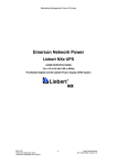
1
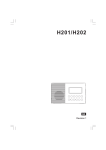
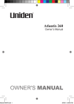
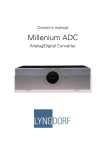
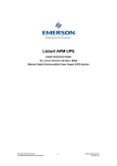
Voyager OM ***NEW***.indd 1
Voyager
Owner’s Manual
14/4/08 3:18:45 PM
Contents
Contents.................................................................................................1
Controls and Indications.........................................................................2
LCD Display....................................................................................3
Warning!.................................................................................................4
Lithium Ion Battery Pack Warning...................................................4
Introduction.............................................................................................5
Features..........................................................................................5
Technical Support and Service.......................................................5
Included in your Package.......................................................................6
Getting Started.......................................................................................7
Mounting the Drop-in Charger........................................................7
Attaching the Antenna . ..................................................................7
Attaching the Battery Pack.............................................................8
Attaching the Beltclip......................................................................8
Charging the Battery Pack..............................................................9
SPKR/MIC Jack Cap......................................................................9
Connecting the SPKR/MIC.............................................................9
Operation..............................................................................................10
Turning On the Unit and Setting Squelch.....................................10
Selecting a Channel......................................................................11
One-touch Channel 16/9...............................................................12
Triple Watch..................................................................................12
Programming a Channel into Memory..........................................13
Deleting a Channel from Memory.................................................13
Scanning.......................................................................................13
Transmitting..................................................................................14
Lighted Keys and Display.............................................................15
Battery Indicator............................................................................15
Key Lock.......................................................................................15
Tone Enable/Disable.....................................................................16
Back Light Function Enable/Disable.............................................16
Troubleshooting....................................................................................17
Specifications.......................................................................................18
International Marine VHF Channel Chart.............................................19
Warranty...............................................................................................22
Voyager OM ***NEW***.indd 1
14/4/08 3:18:46 PM
Controls and Indicators
1. Antenna
2. Belt Clip
3. Battery
4. Battery Release Clip
5. PTT (Push to Talk) Key
6. Triple Watch Button (TRI)
7. Lock Button (LOCK)
8. TX Power / (1/5W)
9. Microphone
10. Speaker MIC Jack / Cap
11. Volume / Power Knob
12. Squelch Knob
13. LCD Display
14. Memory Button (MEM)
15. Scan Button (SCAN)
16. Channel Up Button
17. 16/9 Button (16/9)
18. Channel Down Button
19. Speaker
Voyager OM ***NEW***.indd 2
14/4/08 3:18:47 PM
Controls and Indicators
LCD Display
A
E
F
G
A
B
C
D
E
F
G
H
H
This indicator will appear only when the PTT switch is pressed
and the radio is sending a transmission (TX).
This indicator indicate whether the transmitting power is 1W or
5W.
Channel Number Display.
This indicator will be displayed if the displayed channel is a memory (MEM) channel for scanning.
This Indicator will be displayed while in SCAN mode.
Battery Indicator - When battery is fully charged the display would
look as the sample display. Battery levels are six levels of 0 to 5,
which consist of five indicators.
This indicator will be displayed when TRIPLE WATCH is on.
This indicator will appear only when key LOCK function is on.
Voyager OM ***NEW***.indd 3
14/4/08 3:18:48 PM
Warning!
•
•
•
•
•
The VOYAGER is waterproof only when both the antenna, speaker mic cap and the battery are properly attached.
Do not operate the transmitter of any radio equipment unless
all the Radio Frequency (RF) connectors are secure
and any open connectors are properly terminated.
Do not operate the transmitter of any radio equipment near
electrical blasting caps or in an explosive atmosphere.
Do not let children operate any transmitter-equipped radio
equipment without proper supervision.
Have your radio equipment serviced by a qualified technician.
CAUTION
Lithium Ion Battery Pack Warning
• This equipment contains a Lithium Ion Battery Pack.
• Avoid exposing the Lithium Ion battery, attached or unattached
to the radio, in direct sunshine, heated cars, or in areas with
temperatures below -20°C (-4°F) or above +60°C (+140°F).
Exposing the chemicals contained within the battery pack to
temperatures above +60°C (+140°F) may cause the battery to
rupture, fail or reduce performance.
• In case of exposure to cell contents, wash the affected area
thoroughly, and seek medical attention.
• The Lithium Ion Battery Pack contained in this equipment may
explode if disposed of in a fire.
• Do not short-circuit the Battery Pack.
• Do not charge the Lithium Ion Battery Pack used in this
equipment in any charger other than the one designed to charge
this Battery Pack. Using another charger may damage the Battery
Pack or cause the Battery Pack to explode.
• Lithium Ion batteries must be disposed of properly.
Voyager OM ***NEW***.indd 4
14/4/08 3:18:48 PM
Introduction
The VOYAGER is a waterproof, portable two-way VHF transceiver.
It is compact, lightweight, rugged and fits easily in your hand. This
handheld VHF marine radio will give you consistent, outstanding
performance in virtually all conditions and situations.
To ensure that you get the most from the Voyager features,
please read this operating guide carefully before using
the unit.
Features
• Waterproof (meets JIS7 waterproof specifications: submersible at 1.0m depth for up to 30minutes)*
• Triple Watch Mode
• Priority Channel Startup (Channel 16)
• Programmable Memory
• One-Touch Channel 16/9
• Memory Scan
• International Channels
• Table-Top Drop-In Charger (can also be wall-mounted)
• Rechargeable Lithium Ion Battery Pack
• Battery Save Operation
• Key Lock
• Back-Lit Keys and Display
• Belt Clip
• Wrist Strap
• TX Power 1W/5W
* The VOYAGER radio meets waterproof (JIS7) specifications only
when the battery, the antenna and speaker MIC jack cap are correctly
installed. The VOYAGER will retain its JIS7 rating when the accessory
Speaker MIC is connected correctly but the Speaker MIC itself is not
splash or waterproof.
Technical Support and Service
If your marine radio does not perform properly, follow the
troubleshooting tips in the back of this operating guide.
Unauthorized adjustment will void the warranty.
Voyager OM ***NEW***.indd 5
14/4/08 3:18:48 PM
Voyager OM ***NEW***.indd 6
Included in your Package
VOYAGER
AC Adapter
Antenna
DC Adapter
Drop-in Charger
Lithium Battery
Beltclip
Wrist Strap
Mounting Screws
Reference Guide/
Printed Material
Speaker Microphone
SM078
14/4/08 3:18:50 PM
Getting Started
Mounting the Drop-in Charger
1
Mount the drop-in charger to either a counter
or wall.
To counter:
Attach the drop-in charger
using the mounting screws
and washers as follows.
To wall:
Insert the two mounting
screws into the wall keeping
the same space as the holes
on the charger.
2
Place the charger with the
screws through the larger
holes then turn the charger.
3
Plug one end of the AC
adapter into the wall outlet
and the other end
into the drop-in charger.
4
When you mount the drop-in
charger on your boat, use
the DC adapter instead.
Attaching the Antenna
Attach the antenna to the VOYAGER.
Be sure the antenna is firmly seated.
Voyager OM ***NEW***.indd 7
14/4/08 3:18:51 PM
Getting Started
Attaching the Battery Pack
Contacts
Place the battery pack onto the back of
1 the radio. It will only fit in one way.
2
Snap the battery release clip until it
clicks. Be sure the battery pack fits
tightly against the VOYAGER’s body.
Attaching the Beltclip
1
Hold the beltclip in the direction as
follows.
2
Apply it to the hanger piece on the back
of the radio. Then slide it up.
3
You will hear a click. The beltclip is
firmly attached.
4
To take the beltclip off the radio, turn it
and slide it up.
Voyager OM ***NEW***.indd 8
14/4/08 3:18:52 PM
Getting Started
Charging the Battery Pack
Your marine radio is powered by a specially designed Lithium Ion
battery pack.
• Before operating the VOYAGER, charge the Lithium Ion battery
pack for 6 hours without interruption in the drop-in charger.
1
2
•
•
•
Place the VOYAGER in the drop-in charger.
The red LED illuminates and stays on.
The charger won’t overcharge the battery pack. When charging is completed, the charge LED is no longer illuminated.
Do not transmit when the VOYAGER is in the drop-in charger!
You can monitor incoming calls while the VOYAGER is in the drop-in charger.
SPKR/MIC Jack Cap
Make sure the SPKR/MIC jack cap is
screwed tight to maintain submersible
rating. Tighten the screw cap clockwise
with the use of a coin.
Connecting the SPKR/MIC
Unscrew the SPKR/MIC jack cap to plug in the SPKR/MIC. Secure the
SPKR/MIC plug by tightening the plug screw clockwise.
Voyager OM ***NEW***.indd 9
Strong Signals
Medium Signals
Weak Signals
Noise
14/4/08 3:18:53 PM
Operation
•
•
•
See “Controls and Indicators” (page. 2) for button, knob, and key positions.
When you turn on your VOYAGER, it is automatically tuned to channel 16, frequency for distress, safety, and calling.
When you press any key (except PTT), a short tone sounds.
Turning On the Unit and Setting Squelch
1
Before you turn on the unit, turn the
Squelch knob fully counterclockwise.
2
Then, turn on the unit by turning the
Volume/Power knob clockwise until you
hear a hissing sound.
3
Turn the Squelch knob clockwise, just until
the hissing sound stops. Use the knob to
adjust to the desired squelch level. Think of
the squelch control as a frequency gate
which controls access to weak or strong Strong Signals
signals depending on its setting.
Medium Signals
•
Weak Signals
To listen to a weak or distant station,
turn the knob counterclockwise.
Noise
If reception is poor, turn it clockwise to
cut out weak transmissions.
If the squelch control is adjusted so you continually hear a hissing sound, the unit will not scan properly.
4
To turn off the unit, turn the Volume/Power knob
counterclockwise until it clicks.
•
Voyager OM ***NEW***.indd 10
10
14/4/08 3:18:54 PM
Operation
Selecting a Channel
1
Turn on your VOYAGER.
2
To select a higher channel,
button.
press the
3
To select a lower channel,
button.
press the
•
[UP ]
[DOWN ]
To change the channel continuously,
or
button for
press and hold the
more than 1 second.
Voyager OM ***NEW***.indd 11
11
14/4/08 3:18:55 PM
[DOWN ]
Operation
One-touch Channel 16/9
Example: While you are monitoring channel 20, you want to check
channel 16 or channel 9.
1
You are now on channel 20.
2
To monitor channel 16, press the
16/9 button.
3
To monitor channel 9, press the
16/9 button again.
4
To return to channel 20, press the
16/9 button again.
Triple Watch
Triple Watch mode monitors channels 16 and
9 for a signal while you listen to the currently
selected channel. The marine radio checks
channel 16 and 9 for activity every 2 seconds.
1
To select Triple Watch mode, press the TRI button.
“TRIPLE” appears on the display.
2
To exit from Triple Watch, press the
TRI button again.
“TRIPLE” disappears on the display.
Voyager OM ***NEW***.indd 12
12
14/4/08 3:18:56 PM
Operation
•
•
•
While in Triple Watch mode, you can change the currently selected
or
button.
channel using the
A momentary press of the 16/9 button interrupts Triple Watch mode
and remains on 16, or on channel 9 if you press once more. To
return to the previous mode, simply press the button again.
It becomes Dual Watch when Triple Watch function is turned on while CH9 or CH16 is displayed.
Programming a Channel into Memory
Before using the scanning feature, you have to program channels
into memory.
1
Select the channel to enter into memory
or
button.
by pressing the
2 Press the MEM button to store the
channel.
MEM appears on the display.
Deleting a Channel from Memory
Select the channel to delete from
1
or
memory by pressing the
button.
2 Press the MEM button.
MEM disappears from the display.
Scanning
1
To begin scanning the programmed
channels, press the SCAN button.
SCAN and TRIPLE appear on the
display.
Voyager OM ***NEW***.indd 13
13
14/4/08 3:18:58 PM
Operation
To stop scanning, press the SCAN button once more. SCAN and
2 TRIPLE disappear from the display.
•
•
Scanning starts from the lowest to highest channel and stops
when it finds an active channel. It remains on that channel until
the transmission ends, then resumes scanning after a 3 second
delay period.
When in the scan mode, the unit automatically activates the
Triple Watch feature. To deactivate Triple Watch from the
scanning mode, press the TRI button.
TRIPLE disappears from the display.
Transmitting
1
Transmission power can be set to either
5W or 1W.
Press the 1/5W button to make
the change, then the 5W or the 1W
indicator on the display changes
accordingly.
TX Power will be set to 5W when is changed to 16CH. The TX
Power is able to change to 1 W at 16CH by pressing 1/5W.
2
To transmit, press and hold the PTT key.
TX appears on the display.
3
To return to receive, release the PTT key.
TX disappears from the display.
•
•
If the PTT key is pressed for more than 5 minutes, TX starts
blinking and the transmission ends. The TX time out tone will
sound until the PTT key is released.
If the battery indicator drops to the 1-mark level on the display,
when the PTT key is pressed, the radio will not transmit and the
TX icon starts blinking. (Refer to the description of the Battery Indicator on the next page.)
Voyager OM ***NEW***.indd 14
14
14/4/08 3:18:58 PM
Operation
Lighted Keys and Display
To light the display, press any key excluding the PTT key.
• If you press any button other than the PTT key while the display
and keypad are illuminated, it remains illuminated for another
5 seconds.
Battery Indicator
When the unit is on, battery power is always indicated on the
display.
When the battery is fully charged, the battery
indicator appears as follows:
When the battery is nearly discharged, the
battery indicator appears as follows:
•
When the battery indicator drops to the
1-mark level on the display, the radio will
receive but will not transmit.
Key Lock
To prevent accidental entries, you can lock the keypad.
1 Press and hold the LOCK key for 1.5 seconds. The unit
will beep two times to confirm that the keypad is locked with
LOCK indication on the display.
2 To unlock the keypad, press and hold the LOCK key
again for 1.5 seconds. The unit will beep twice to confirm that
the keypad is unlocked, and LOCK will disappear.
•
You can also unlock the keypad by turning the radio off and
then on again.
Voyager OM ***NEW***.indd 15
15
14/4/08 3:18:59 PM
Operation
Tone Enable/Disable
The Tone sounds can de enabled/disabled as follows;
1
Turn on the radio while pushing and holding [ ] sw.
The Tone enable/disable will be switched.
* When Tone enable is selected, all the tone sounds.
* When Tone disable is selected, all the tone does not sound.
When power switch is turned on without pressing [ ] sw, the previous
setting of Tone enable/disable is kept.
Back Light Function Enable/Disable
This Back Light Function can be enabled/disabled as follows;
1
Turn on the radio while pushing and holding [ ] sw.
The Back Light function enable/disable will be switched.
* When Back Light enable is selected, Back Light function activates.
* When Back Light disable is selected, Back Light function does not activate.
When power switch is turned on without pressing [ ] sw, the previous
setting of Back Light enable/disable is kept.
Voyager OM ***NEW***.indd 16
16
14/4/08 3:18:59 PM
Troubleshooting
•
•
•
Will not transmit on 5 watt range but will transmit on the 1
watt range
Cause: Low voltage
➾ Recharge or replace the batteries
Will not transmit while on the charger
Cause: Low voltage
➾ The unit is not designed to transmit while on the charger. The
charger does not supply enough power for transmitting.
Battery will not charge
Cause: Charger inoperative
➾ Replace charger. Damage to the charger can be a result of
keying up the radio while on the charger.
Voyager OM ***NEW***.indd 17
17
14/4/08 3:19:00 PM
Specifications
General
Channels Transmit Receive Frequency Control Frequency Tol. Transmit Receive Oper. Temp. Antenna Microphone Display Speaker Power Source Size (without antenna) Weight (w/battery & antenna) 56 International
57 International
PLL
± 1 PPM (at 25 ° C)
± 1 PPM (at 25° C)
-20°C to + 55°C
Flexible Whip
Built-in Electret type
Liquid Crystal Display
8 ohms, 1 Watt
Rechargeable Lithium Ion
Battery Pack 7.4V 850 mAh
97 (H) x 62 (W) x 33 (D) mm
8.8 oz (250g)
Transmitter
Frequency Range Power Output Spurious Emissions Current Drain 156.025 MHz to 157.425 MHz
1.0 W & 5 W
-38 dBm (5W)
500mA (1W), 1400mA (5W)
Receiver
Receiver Type Frequency Range Sensitivity Squelch Sensitivity Audio Frequency Response
Adjacent Channel Audio Output Power Current Drain Squelched Max. audio Voyager OM ***NEW***.indd 18
Double Conversion Super
Heterodyne Phase
156.300 MHz to 162.000 MHZ
0.45uV for 20dB SINAD
Threshold 0.25μV
± 6 dB 500 to 2010 Hz
70 dB @ ± 25 kHz
0.6 W @ 10 % THD
40 mA
250 mA
18
14/4/08 3:19:00 PM
Marine Channels - International
Channel
Desig
01
02
03
04
05
06
07
08
09
10
11
12
13
14
15
16
17
18
19
20
21
22
23
24
25
26
27
28
60
61
62
63
64
Frequency (MHz)
Traffic Type
Transmit Receive
156.050
156.100
156.150
156.200
156.250
156.300
156.350
156.400
156.450
156.500
156.550
156.600
156.650
156.700
156.750
156.800
156.850
156.900
156.950
157.000
157.050
157.100
157.150
157.200
157.250
157.300
157.350
157.400
156.025
156.075
156.125
156.175
156.225
Voyager OM ***NEW***.indd 19
160.650
Duplex
160.700
Duplex
160.750
Duplex
160.800
Duplex
160.850
Duplex
156.300
160.950
Duplex
156.400
156.450
156.500
156.550
156.600
156.650
156.700
156.750
156.800
156.850
161.500
Duplex
161.550
Duplex
161.600
Duplex
161.650
Duplex
161.700
Duplex
161.750
Duplex
161.800
Duplex
161.850
Duplex
161.900
Duplex
161.950
Duplex
162.000
Duplex
160.625
Duplex
160.675
Duplex
160.725
Duplex
160.775
Duplex
160.825
Duplex
Ship to Ship
Yes
Yes
Yes
Yes
Yes
Yes
Yes
Yes
Yes
Yes
Yes
No
Yes
Yes
Yes
Yes
Yes
Yes
No
No
No
No
No
No
No
No
No
No
Ship to Permanent
Shore Scan List
Yes
Yes
Yes
Yes
Yes
No
Yes
No
Yes
Yes
Yes
Yes
Yes
Yes
Yes
Yes
Yes
Yes
Yes
Yes
Yes
Yes
Yes
Yes
Yes
Yes
Yes
Yes
19
14/4/08 3:19:00 PM
Marine Channels - International
Channel Frequency (MHz)
Traffic Type
Desig Transmit Receive
65
156.275 160.875
Duplex
66
156.325 160.925
Duplex
67
156.375 156.375
68
156.425 156.425
69
156.475 156.475
70
RX Only 156.525
71
156.575 156.575
72
156.625 156.625
73
156.675 156.675
74
156.725 156.725
75
156.775 156.775
1W
76
156.825 156.825
1W
77
156.875 156.875
78
156.925 161.525
Duplex
79
156.975 161.575
Duplex
80
157.025 161.625
Duplex
81
157.075 161.675
Duplex
82
157.125 161.725
Duplex
83
157.175 161.775
Duplex
84
157.225 161.825
Duplex
85
157.275 161.875
Duplex
86
157.325 161.925
Duplex
87
157.375 157.375
88
157.425 157.425
Voyager OM ***NEW***.indd 20
Ship to Ship
Ship to Permanent
Shore Scan List
Yes
Yes
Yes
Yes
Yes
Yes
Yes
No
Yes
Yes
Yes
Yes
Yes
Yes
Yes
Yes
Yes
Yes
Yes
Yes
Yes
Yes
Yes
Yes
No
No
No
Yes
Yes
No
Yes
Yes
No
No
No
Yes
Yes
Yes
Yes
Yes
Yes
Yes
Yes
Yes
Yes
No
20
14/4/08 3:19:01 PM
Voyager OM ***NEW***.indd 21
Memo
21
14/4/08 3:19:01 PM
Warranty
UNIDEN Voyager
Two Year Limited Warranty
IMPORTANT Evidence of the original purchase is required for warranty service.
Warrantor: Uniden Australia Pty Limited A.B.N. 58 001 865 498
Uniden New Zealand Limited
Elements of Warranty: Uniden warrants to the original retail owner for the duration
of this warranty its Voyager (hereinafter referred to as the Product), to be free from
defects in materials and craftsmanship with only the limitations or exclusions set out
below.
Warranty Duration: This warranty to the original retail owner only is only valid in the
original country of purchase and shall be of no further effect 2 years after the date of
original retail sale. This warranty will be deemed invalid if the Product is: (A) Damaged
or not maintained as reasonable and necessary, (B) Modified, altered or used as part
of any conversion kits, subassemblies, or any configurations not sold by Uniden, (C)
Improperly installed, (D) Repaired by someone other than an authorized Uniden Repair
Agent for a defect or malfunction covered by this warranty, (E) Used in conjunction with
any equipment or parts or as a part of a system not manufactured by Uniden. (F) Only
available in the original country of sale.
Parts Covered: This warranty covers for two (2) years, the Product and included accessories.
Statement of Remedy: In the event that the Product does not conform to this warranty
at any time while this warranty is in effect, the warrantor, at its discretion, will repair the
defect or replace the Product and return it to you without charge for parts and service.
This warranty does not provide for reimbursement or payment of incidental or consequential damages. This EXPRESS WARRANTY is in addition to and does not in any
way affect your rights under the TRADE PRACTICES ACT 1974 (Cth) (Australia) or the
CONSUMER GUARANTEES ACT (New Zealand).
Procedure for obtaining performance or warranty: in the event that the Product
does not conform to this warranty, the Product should be shipped or delivered, freight
prepaid, with evidence of original purchase (e.g. a copy of the sales docket) to the
warrantor at:
UNIDEN AUSTRALIA PTY LTD UNIDEN NEW ZEALAND LTD
Service Division Service Division
345 Princes Highway, 150 Harris Road, East Tamaki,
Rockdale, NSW 2216 Auckland
Fax (02) 9599 3278 Fax (09) 274 4253
www.uniden.com.au www.uniden.co.nz
Voyager OM ***NEW***.indd 22
22
14/4/08 3:19:01 PM
© 2008 Uniden Australia Pty Limited/Uniden New Zealand Limited
Printed in China UTZZ01626ZZ(0)
Voyager OM ***NEW***.indd 23
14/4/08 3:19:01 PM