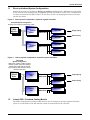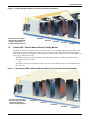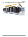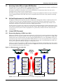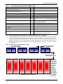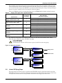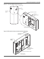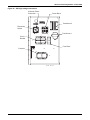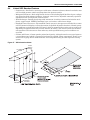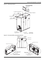
1
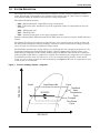
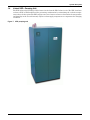
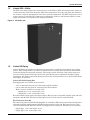
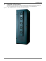
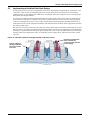
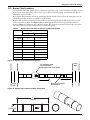
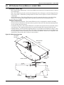
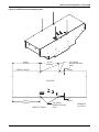
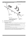
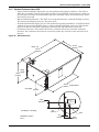
Precision Cooling for
Business Critical Continuity
Liebert Xtreme Density™
System Design Manual
TABLE OF CONTENTS
1.0
SYSTEM DESCRIPTION . . . . . . . . . . . . . . . . . . . . . . . . . . . . . . . . . . . . . . . . . . . . . . . . . . . .1
1.1
Direct and Indirect System Configurations . . . . . . . . . . . . . . . . . . . . . . . . . . . . . . . . . . . . . . . 2
1.2
Liebert XDO—Overhead Cooling Module . . . . . . . . . . . . . . . . . . . . . . . . . . . . . . . . . . . . . . . . . 2
1.3
Liebert XDV—Vertical Above-Cabinet Cooling Module. . . . . . . . . . . . . . . . . . . . . . . . . . . . . . 3
1.4
Liebert XDP—Pumping Unit. . . . . . . . . . . . . . . . . . . . . . . . . . . . . . . . . . . . . . . . . . . . . . . . . . . 5
1.5
Liebert XDC—Chiller. . . . . . . . . . . . . . . . . . . . . . . . . . . . . . . . . . . . . . . . . . . . . . . . . . . . . . . . . 6
1.6
Liebert XD Piping. . . . . . . . . . . . . . . . . . . . . . . . . . . . . . . . . . . . . . . . . . . . . . . . . . . . . . . . . . . . 6
1.7
Liebert XDA—Air Flow Enhancer. . . . . . . . . . . . . . . . . . . . . . . . . . . . . . . . . . . . . . . . . . . . . . . 7
2.0
STARTING A NEW EQUIPMENT COOLING PROJECT. . . . . . . . . . . . . . . . . . . . . . . . . . . . . . . .8
2.1
Determining Cooling Equipment Needs . . . . . . . . . . . . . . . . . . . . . . . . . . . . . . . . . . . . . . . . . . 8
2.2
Implementing a Hot-Aisle/Cold Aisle Design . . . . . . . . . . . . . . . . . . . . . . . . . . . . . . . . . . . . . . 9
3.0
DESIGNING A LIEBERT XD SOLUTION . . . . . . . . . . . . . . . . . . . . . . . . . . . . . . . . . . . . . . . . 10
3.1
Determine Cooling Requirements and Select Liebert XD System . . . . . . . . . . . . . . . . . . . . 10
3.2
Calculate the Heat Load to be Handled by Liebert XD System . . . . . . . . . . . . . . . . . . . . . . 10
3.3
Selecting Liebert XDO or Liebert XDV Modules . . . . . . . . . . . . . . . . . . . . . . . . . . . . . . . . . . 11
3.4
Airflow Requirements for Liebert XD Solutions. . . . . . . . . . . . . . . . . . . . . . . . . . . . . . . . . . . 11
3.5
Liebert XDO Placement . . . . . . . . . . . . . . . . . . . . . . . . . . . . . . . . . . . . . . . . . . . . . . . . . . . . . . 11
3.5.1
3.5.2
Determining Spacing of XDOs in an Aisle . . . . . . . . . . . . . . . . . . . . . . . . . . . . . . . . . . . . . . . . 11
Determining Vertical Placement of Liebert XDOs Above the Cold Aisle . . . . . . . . . . . . . . . . 12
3.6
Liebert XDV Unit Placement. . . . . . . . . . . . . . . . . . . . . . . . . . . . . . . . . . . . . . . . . . . . . . . . . . 13
3.7
Liebert XDP/XDC Placement. . . . . . . . . . . . . . . . . . . . . . . . . . . . . . . . . . . . . . . . . . . . . . . . . . 14
3.8
Examples of Expansion and Interlaced Connection of Liebert XD Cooling Modules . . . . . . 14
3.9
Liebert XD Coolant™ . . . . . . . . . . . . . . . . . . . . . . . . . . . . . . . . . . . . . . . . . . . . . . . . . . . . . . . . 17
3.10
Liebert XD Piping System Design . . . . . . . . . . . . . . . . . . . . . . . . . . . . . . . . . . . . . . . . . . . . . . 17
3.11
Liebert XD Piping Slope. . . . . . . . . . . . . . . . . . . . . . . . . . . . . . . . . . . . . . . . . . . . . . . . . . . . . . 18
3.12
Bypass Flow Controllers . . . . . . . . . . . . . . . . . . . . . . . . . . . . . . . . . . . . . . . . . . . . . . . . . . . . . 19
3.13
Determining Coolant Volume . . . . . . . . . . . . . . . . . . . . . . . . . . . . . . . . . . . . . . . . . . . . . . . . . 20
3.13.1 Liebert XDP/XDC Pumped R-134a Circuit Volume . . . . . . . . . . . . . . . . . . . . . . . . . . . . . . . . . 20
3.14
Liebert XDC DX R-407c Circuit Volume—Air Cooled Units . . . . . . . . . . . . . . . . . . . . . . . . . 21
3.15
Chilled Water Piping . . . . . . . . . . . . . . . . . . . . . . . . . . . . . . . . . . . . . . . . . . . . . . . . . . . . . . . . 21
3.16
Electrical . . . . . . . . . . . . . . . . . . . . . . . . . . . . . . . . . . . . . . . . . . . . . . . . . . . . . . . . . . . . . . . . . . 21
4.0
XD OVERHEAD COOLING MODULE—LIEBERT XDO . . . . . . . . . . . . . . . . . . . . . . . . . . . . . 22
4.1
Liebert XD Vertical Top Cooler (XDV) . . . . . . . . . . . . . . . . . . . . . . . . . . . . . . . . . . . . . . . . . . 24
4.1.1
4.1.2
Standard Features Liebert XDV . . . . . . . . . . . . . . . . . . . . . . . . . . . . . . . . . . . . . . . . . . . . . . . . 24
Optional Features Liebert XDV. . . . . . . . . . . . . . . . . . . . . . . . . . . . . . . . . . . . . . . . . . . . . . . . . 25
4.2
Liebert XD Piping Dimensions and Features . . . . . . . . . . . . . . . . . . . . . . . . . . . . . . . . . . . . . 30
4.3
Liebert XDP Standard Features . . . . . . . . . . . . . . . . . . . . . . . . . . . . . . . . . . . . . . . . . . . . . . . 32
4.4
Liebert XDC Standard Features . . . . . . . . . . . . . . . . . . . . . . . . . . . . . . . . . . . . . . . . . . . . . . . 36
5.0
SPECIFICATIONS . . . . . . . . . . . . . . . . . . . . . . . . . . . . . . . . . . . . . . . . . . . . . . . . . . . . . . . .41
i
FIGURES
Figure 1
Figure 2
Figure 3
Figure 4
Figure 5
Figure 6
Figure 7
Figure 8
Figure 9
Figure 10
Figure 11
Figure 12
Figure 13
Figure 14
Figure 15
Figure 16
Figure 17
Figure 18
Figure 19
Figure 20
Figure 21
Figure 22
Figure 23
Figure 24
Figure 25
Figure 26
Figure 27
Figure 28
Figure 29
Figure 30
Figure 31
Figure 32
Figure 33
Figure 34
Figure 35
Figure 36
Figure 37
Figure 38
Figure 39
Figure 40
Figure 41
Figure 42
Figure 43
Figure 44
Figure 45
Pressure enthalpy diagram - refrigerant. . . . . . . . . . . . . . . . . . . . . . . . . . . . . . . . . . . . . . . . . . . . . . 1
Direct system configuration—hydraulic system schematic . . . . . . . . . . . . . . . . . . . . . . . . . . . . . . . 2
Indirect system configuration—hydraulic system schematic. . . . . . . . . . . . . . . . . . . . . . . . . . . . . . 2
Suspended XDO modules in hot aisle-cold aisle arrangement. . . . . . . . . . . . . . . . . . . . . . . . . . . . . 3
Top-mounted XDV modules with fixed piping in hot aisle-cold aisle arrangement . . . . . . . . . . . . 3
Top-mounted XDV modules with flexible piping in hot aisle-cold aisle arrangement . . . . . . . . . . 4
XDP pumping unit . . . . . . . . . . . . . . . . . . . . . . . . . . . . . . . . . . . . . . . . . . . . . . . . . . . . . . . . . . . . . . . 5
XD Chiller unit . . . . . . . . . . . . . . . . . . . . . . . . . . . . . . . . . . . . . . . . . . . . . . . . . . . . . . . . . . . . . . . . . . 6
XDA—air flow enhancer—on Liebert Foundation enclosure . . . . . . . . . . . . . . . . . . . . . . . . . . . . . . 7
Hot aisle-cold aisle arrangement with under-floor source . . . . . . . . . . . . . . . . . . . . . . . . . . . . . . . . 9
XDO placement over cold aisle . . . . . . . . . . . . . . . . . . . . . . . . . . . . . . . . . . . . . . . . . . . . . . . . . . . . . 11
XDO spacing—horizontal and vertical . . . . . . . . . . . . . . . . . . . . . . . . . . . . . . . . . . . . . . . . . . . . . . 12
Positioning Liebert XDV on top of cabinet . . . . . . . . . . . . . . . . . . . . . . . . . . . . . . . . . . . . . . . . . . . 13
XDV units mounted on racks emitting 3kW of heat top view . . . . . . . . . . . . . . . . . . . . . . . . . . . . 14
XDV units mounted on racks emitting 5kW of heat top view . . . . . . . . . . . . . . . . . . . . . . . . . . . . 15
XDV units mounted on racks emitting 8kW of heat top view . . . . . . . . . . . . . . . . . . . . . . . . . . . . 15
XDV units mounted on racks emitting 16kW of heat top view . . . . . . . . . . . . . . . . . . . . . . . . . . . 16
Piping for XDP/XDC used with XDO or XDV units . . . . . . . . . . . . . . . . . . . . . . . . . . . . . . . . . . . . 17
Hydraulic schematic . . . . . . . . . . . . . . . . . . . . . . . . . . . . . . . . . . . . . . . . . . . . . . . . . . . . . . . . . . . . . 18
Bypass flow controller arrangement . . . . . . . . . . . . . . . . . . . . . . . . . . . . . . . . . . . . . . . . . . . . . . . . 19
Bypass flow controller details, dimensions . . . . . . . . . . . . . . . . . . . . . . . . . . . . . . . . . . . . . . . . . . . 19
XDO dimensional data . . . . . . . . . . . . . . . . . . . . . . . . . . . . . . . . . . . . . . . . . . . . . . . . . . . . . . . . . . . 22
XDO16 internal mounting location . . . . . . . . . . . . . . . . . . . . . . . . . . . . . . . . . . . . . . . . . . . . . . . . . 23
XDO top and front electrical access points . . . . . . . . . . . . . . . . . . . . . . . . . . . . . . . . . . . . . . . . . . . 24
XDV dimensions . . . . . . . . . . . . . . . . . . . . . . . . . . . . . . . . . . . . . . . . . . . . . . . . . . . . . . . . . . . . . . . . 25
XDV dimensions with factory-installed flex pipe . . . . . . . . . . . . . . . . . . . . . . . . . . . . . . . . . . . . . . 26
XDV electrical connections . . . . . . . . . . . . . . . . . . . . . . . . . . . . . . . . . . . . . . . . . . . . . . . . . . . . . . . . 27
Suspending single XDV from Unistruts . . . . . . . . . . . . . . . . . . . . . . . . . . . . . . . . . . . . . . . . . . . . . 28
Suspending single XDV from the roof structure . . . . . . . . . . . . . . . . . . . . . . . . . . . . . . . . . . . . . . . 28
Alternative mounting methods—mounting multiple XDV units . . . . . . . . . . . . . . . . . . . . . . . . . . 29
Five-port prefabricated piping for XDV modules . . . . . . . . . . . . . . . . . . . . . . . . . . . . . . . . . . . . . . 30
Two-port prefabricated piping for XDV modules . . . . . . . . . . . . . . . . . . . . . . . . . . . . . . . . . . . . . . 31
XDP dimensions, access points and external features . . . . . . . . . . . . . . . . . . . . . . . . . . . . . . . . . . 33
Front view of XDP and electrical enclosure. . . . . . . . . . . . . . . . . . . . . . . . . . . . . . . . . . . . . . . . . . . 34
XDP electrical enclosure knockout locations for field wiring . . . . . . . . . . . . . . . . . . . . . . . . . . . . . 34
XDP high voltage connections . . . . . . . . . . . . . . . . . . . . . . . . . . . . . . . . . . . . . . . . . . . . . . . . . . . . . 35
XDC dimensional data . . . . . . . . . . . . . . . . . . . . . . . . . . . . . . . . . . . . . . . . . . . . . . . . . . . . . . . . . . . 36
XDC piping locations . . . . . . . . . . . . . . . . . . . . . . . . . . . . . . . . . . . . . . . . . . . . . . . . . . . . . . . . . . . . 37
Front view of XDC and electrical enclosures. . . . . . . . . . . . . . . . . . . . . . . . . . . . . . . . . . . . . . . . . . 37
XDC electrical enclosure knockout locations for field wiring . . . . . . . . . . . . . . . . . . . . . . . . . . . . . 38
XDC high voltage connections—primary disconnect switch. . . . . . . . . . . . . . . . . . . . . . . . . . . . . . 38
XDC high voltage connections—secondary disconnect switch . . . . . . . . . . . . . . . . . . . . . . . . . . . . 39
XDC heat rejection electrical connection points . . . . . . . . . . . . . . . . . . . . . . . . . . . . . . . . . . . . . . . 39
XDC electrical enclosure knockout locations for ELV. . . . . . . . . . . . . . . . . . . . . . . . . . . . . . . . . . . 40
XDC ELV field connections points . . . . . . . . . . . . . . . . . . . . . . . . . . . . . . . . . . . . . . . . . . . . . . . . . . 40
ii
TABLES
Table 1
Table 2
Table 3
Table 4
Table 5
Table 6
Table 7
Table 8
Table 9
Table 10
Table 11
Table 12
Table 13
Table 14
Table 15
Calculating quantity and spacing of XDO modules . . . . . . . . . . . . . . . . . . . . . . . . . . . . . . . . . . . .
Determine required number of XDV modules . . . . . . . . . . . . . . . . . . . . . . . . . . . . . . . . . . . . . . . . .
Supply, return pipe sizes—equivalent lengths . . . . . . . . . . . . . . . . . . . . . . . . . . . . . . . . . . . . . . . .
Bypass flow controllers required in a Liebert XD system . . . . . . . . . . . . . . . . . . . . . . . . . . . . . . .
Coolant volume calculations – XDP/XDC with XDV systems . . . . . . . . . . . . . . . . . . . . . . . . . . . .
Coolant volume calculation – XDP/XDC with XDO systems . . . . . . . . . . . . . . . . . . . . . . . . . . . . .
Indoor unit refrigerant charge—R-407C . . . . . . . . . . . . . . . . . . . . . . . . . . . . . . . . . . . . . . . . . . . . .
Outdoor condenser charge—R-407C . . . . . . . . . . . . . . . . . . . . . . . . . . . . . . . . . . . . . . . . . . . . . . . .
Liquid line charge - R-407C refrigerant per 100 ft (30 m) of Type “L” copper tube . . . . . . . . . . .
Five-port prefabricated piping legend . . . . . . . . . . . . . . . . . . . . . . . . . . . . . . . . . . . . . . . . . . . . . . .
Two-port prefabricated piping legend . . . . . . . . . . . . . . . . . . . . . . . . . . . . . . . . . . . . . . . . . . . . . . .
Liebert XDO specifications . . . . . . . . . . . . . . . . . . . . . . . . . . . . . . . . . . . . . . . . . . . . . . . . . . . . . . . .
Liebert XDC specifications . . . . . . . . . . . . . . . . . . . . . . . . . . . . . . . . . . . . . . . . . . . . . . . . . . . . . . . .
Liebert XDV specifications . . . . . . . . . . . . . . . . . . . . . . . . . . . . . . . . . . . . . . . . . . . . . . . . . . . . . . . .
Liebert XDP specifications . . . . . . . . . . . . . . . . . . . . . . . . . . . . . . . . . . . . . . . . . . . . . . . . . . . . . . . .
iii
12
13
18
19
20
20
21
21
21
30
31
41
42
43
44
iv
System Description
1.0
SYSTEM DESCRIPTION
The Liebert XD™ family of cooling units delivers efficient, sensible cooling to high-heat environments. XD systems are designed to cool computer racks and hot zones in a data center or computer
room without taking up expensive floor space for cooling components.
The Liebert XD family includes:
• XDO—XD Overhead unit, suspended from the roof structure
• XDV—XD Vertical unit, mounted on top of the equipment cabinet or suspended from the roof
structure
• XDP—XD Pumping unit
• XDC—XD Chiller unit
• XDA—mounted on the front or rear of the equipment cabinet
Systems combining XDO, XDV units with XDP or XDC units can remove more than 16 kW of heat per
cabinet.
The Liebert XD system also performs at high efficiency rates. Properly spaced cooling modules and
the XD system’s fluid phase change technology, combine to reduce an XD system’s energy consumption to at least 18% less than a traditional cooling system.
The XD family maintains this energy efficiency by employing the heat absorption properties of a liquid (pumped refrigerant) through phased changes. Coolant is pumped as a liquid, becomes a gas
within the heat exchangers of the cooling modules (either the XDO or XDV) and then is returned to
either the XDP or XDC where it condenses to a liquid. This eliminates the compression cycle required
by traditional systems. And, if a leak were to occur, the environmentally friendly coolant would
escape as a gas, causing no harm to critical equipment (see Figure 1).Because no compressor is used
in the circuit, no oil is needed.
Pressure enthalpy diagram - refrigerant
Liquid
PRESSURE
Figure 1
Liquid/Vapor Mix
Vapor
Traditional
Vapor
Compression
Cycle
XDO/XDV
Pumped
Two-Phase
Cycle
ENTHALPY
1
System Description
1.1
Direct and Indirect System Configurations
Liebert XD systems are available in Direct and Indirect configurations—differentiated essentially
by the location of the pumping unit (see Figures 2 and 3). The indirect system uses a pumping unit
to control and circulate the XD Coolant™. In the direct system, the pumping functions are incorporated in the chiller.
Figure 2
Direct system configuration—hydraulic system schematic
Direct XD System Configuration
Pumping and control are performed by chiller.
Liebert
Heat
Rejection
Liebert
XDC Coolant
Chiller
XDO/XDV
Supply Piping
XDCoolant
Return Piping
XDO/XDV
Liebert
XDC Coolant
Chiller
XDO/XDV
XDCoolant
XDO/XDV
Figure 3
Indirect system configuration—hydraulic system schematic
Indirect XD
System Configuration
XDPs pump coolant to XDO and XDV
modules, isolate coolant from building
chilled water supply with an internal
heat exchanger and maintains coolant
above the dew point.
Building
Chilled
Water
Liebert
XDP
XDO/XDV
Supply Piping
XDCoolant
Return Piping
XDO/XDV
Liebert
XDP
1.2
XDO/XDV
XDCoolant
Liebert XDO—Overhead Cooling Module
The XDO ceiling-mounted cooling module draws in hot air rising from densely populated cabinets,
passes it over the XDO’s coils and exhausts cooled air downward into the cold aisle.
2
System Description
Figure 4
Suspended XDO modules in hot aisle-cold aisle arrangement
Cold Aisle
Hot aisles and cold aisles
alternate, taking advantage
of airflow properties to
increase cooling efficiency
1.3
Hot Aisle
Cold Aisle
Hot Aisle
Cold Aisle
Liebert XDV—Vertical Above-Cabinet Cooling Module
The XDV is installed on top of or above a rack enclosure. It is available with optional flexible metal
pipes with automatic shutoff at the ends for easy connection to the XD Coolant distribution pipes.
This flexible piping is available pre-attached and pre-charged with refrigerant. The Liebert XDV may
be set up in either of two ways:
• The XDV can take hot air directly from an equipment enclosure, cool the air and discharge it
downward into the cold aisle.
OR
• The XDV can draw hot air from the room, cool the air and discharge the cool air downward into
the cold aisle.
Figure 5
Top-mounted XDV modules with fixed piping in hot aisle-cold aisle arrangement
Hot aisles and cold aisles
alternate, taking advantage
of airflow properties to
increase cooling efficiency
Cold Aisle
Hot Aisle
Cold Aisle
Hot Aisle
3
Cold Aisle
System Description
Figure 6
Top-mounted XDV modules with flexible piping in hot aisle-cold aisle arrangement
Cold Aisle
Hot Aisle
Hot aisles and cold aisles alternate,
taking advantage of airflow properties
to increase cooling efficiency
Cold Aisle
Hot Aisle
4
System Description
1.4
Liebert XDP—Pumping Unit
The XDP isolates the building’s chilled water circuit from the XD Coolant circuit. The XDP circulates
coolant to XDV or XDO modules while preventing condensation by maintaining the coolant’s temperature above the dew point.The XDP employs two sets of remote sensors to determine the temperature
and humidity in the air and instantly adjusts coolant supply temperature to compensate for changing
conditions.
Figure 7
XDP pumping unit
5
System Description
1.5
Liebert XDC—Chiller
The XDC is an indoor chiller that connects directly to the XDO or XDV units and provides coolant circulation and control. The XDC keeps the XD Coolant temperature above the dew point and eliminates
the need for a separate pumping unit in the direct system configuration. The XDC employs two sets of
remote sensors to determine the temperature and humidity in the air and instantly adjusts coolant
supply temperature to compensate for changing conditions.
Figure 8
1.6
XD Chiller unit
Liebert XD Piping
Liebert XD Piping is prefabricated distribution piping that is installed in anticipation of a growing
system. XDV cooling modules are added as required and are quickly made operational with flexible
connection piping with threaded couplings. This unique system allows the room cooling capacity to
increase to more than 500 Watt per square foot (5400 W/m2) with no additional disruptive piping
installation. The flexible connection piping also allows the cooling modules to be re-positioned without
interruption in operation.
Liebert XD Field Piping Kits
Field piping kits are available in two versions
• 10 ft. (3.05m) with five ports for connecting five XDV modules
• 8 ft. (2.44m) with two ports for connecting two XDV modules
Each version is available in two pipe sizes:
• Supply pipe: 1-1/8"; return pipe: 2-1/8"
• Supply pipe: 1-3/8"; return pipe: 2-5/8"
Each kit contains supply pipe(s) and return pipe(s). Each port has a threaded coupling at the end with
automatic shutoff when disconnected. Each port also has a ball valve for manual shutoff.
XD Connection Port Kit
The connection ports in the XD Field Piping Kits are available as XD Connection Port Kit. Each port has
a threaded coupling, with automatic shutoff when disconnected, at the end. Each port also has a ball
valve for manual shutoff. Each kit contains one supply and one return port. Two kit sizes are available:
• Supply pipe: 1-1/8"; return pipe: 2-1/8"
• Supply pipe:1-3/8"; return pipe: 2-5/8"
6
System Description
1.7
Liebert XDA—Air Flow Enhancer
The XDA is a fan unit that boosts the airflow through densely populated enclosures, removing hot
spots from within the racks. One or two units can be mounted on most rack enclosures.
Figure 9
XDA—air flow enhancer—on Liebert Foundation enclosure
7
Starting a New Equipment Cooling Project
2.0
STARTING A NEW EQUIPMENT COOLING PROJECT
2.1
Determining Cooling Equipment Needs
1.
Is there adequate space available for an XD installation?
2.
Is the hot aisle/cold aisle approach being utilized for this room design or can it
be utilized in this room design?
3.
Is redundant cooling equipment required?
4.
Are there access considerations for all components (possible rigging problems)
5.
What heat load growth is anticipated over the next few years?
6.
How are the cabinets going to be populated (density of heat generation)?
7.
What monitoring requirements are desired or needed?
8.
Who will be involved in this project (stakeholders)?
9.
Is there existing computer room environmental cooling systems for humidity
control and filtration?
10.
Is the vapor barrier sufficient?
11.
Is a chilled water system available?
a.
What is the system’s capacity?
b.
What is the system’s chilled water supply temperature?
c.
Does the chilled water supply temperature vary during the year or is the
temperature constant?
12.
How much power is available for cooling equipment?
13.
What is the maximum distance between the XDP/XDC unit and the farthest
XDO/XDV units in the proposed layout?
14.
If an air cooled XDC is used – is an area available for the remote condenser? ?
8
Starting a New Equipment Cooling Project
2.2
Implementing a Hot-Aisle/Cold Aisle Design
A best practice is to use rows of equipment racks in an alternating arrangement of “cold aisles” and
“hot aisles.” This is best accomplished when the layout of the file-server farm area is first being
planned. and it is exceedingly more difficult to accomplish when the computer room is already populated with operating hardware.
A cold aisle is defined as having perforated floor tiles that allow cooling air to come up from the plenum under the raised floor, and a hot aisle has no perforated tiles. In the cold aisle, the equipment
racks are arranged face to face so the cooling air discharged up through the perforated floor tiles is
sucked into the face of the computer hardware and exhausted out the back of the equipment rack onto
the adjacent hot aisles.
Hot aisles are literally hot because the objective of the alternating cold and hot aisle design is to separate the source of cooling air from hot air discharge which returns to the computer-room cooling unit.
Therefore, no perforated tiles should be placed in the hot aisles. as this would mix hot and cold air and
thereby lower the temperature of the air returning to the cooling units, which reduces their usable
capacity.
Figure 10 Hot aisle-cold aisle arrangement with under-floor source
Heated air expelled from
racks is drawn into
cooling unit and returned
to floor supply
Cold air supplied
through perforated
floor tiles is drawn
into racks
9
Designing a Liebert XD Solution
3.0
DESIGNING A LIEBERT XD SOLUTION
Liebert XD systems are intended for use with precision air conditioning equipment, such as the Liebert Deluxe System/3 and Liebert DS. The precision air conditioning equipment is required to control
the room’s humidity and to filter the air.
The XD systems provide efficient, highly effective heat removal (sensible cooling only), and provide no
dehumidification. The XD control system maintains the coolant temperatures just above the dew
point of the space to prevent condensation. Since the capacity of the system is limited by the dew
point in the space, sufficient dehumidification and an adequate vapor barrier must be provided to
maintain the dew point at or below the level necessary to achieve the required capacity.
In their maximum density configurations, the XDO/XDV system can provide more than 16kW of cooling capacity per rack.
The Liebert XD system is optimized for hot aisle/cold aisle equipment configurations, the industry’s
most highly recommended method for dealing with extremely high heat loads.
Refer to the technical data manual of either the Deluxe System/3 (SL-18100) or the Liebert DS (SL18810) for additional installation and application guidelines that apply to all critical space cooling
applications.
3.1
Determine Cooling Requirements and Select Liebert XD System
1.
2.
3.
4.
5.
3.2
Calculate the total cooling required
Determine placement of the XD units
Determine required pipe sizes
Calculate the coolant volume of the XD systems
Complete design details including, electrical, mounting, piping, etc.
Calculate the Heat Load to be Handled by Liebert XD System
When designing a cooling solution using the XD system, the initial steps are similar to those required
to cool a conventional critical space. The total heat load must be calculated, including sensible and
latent cooling requirements. These should be increased by the reserve capacity needed for pull-down
situations where the room temperature must be reduced and to provide for unexpected increases in
heat load.
NOTE
Reserve capacity is distinct from redundant capacity in that redundant capacity may or may
not be available concurrently with normal operating capacity. Reserve capacity is available
concurrently with normal operating capacity.
The next step is to determine how much of the required cooling capacity is to be provided by Liebert
Deluxe or Liebert DS units. If the facility is new, typically up to 150 watts per square foot (1500 watts
per m2) of cooling can be obtained from Liebert precision air conditioning units supplying air through
a raised floor. In existing facilities, such factors as raised floor height, under-floor obstructions or
other limitations may reduce this to less than 50 watts per square foot (500 watts per m2).
Once the total required sensible cooling capacity is known, subtract the sensible cooling portion to be
provided by Liebert Deluxe or Liebert DS units. This yields the cooling capacity to be provided by the
XD system.
10
Designing a Liebert XD Solution
3.3
Selecting Liebert XDO or Liebert XDV Modules
The next step is to select XDO or XDV cooling modules to be configured into the solution. An XDO and
an XDV can be connected to the same XDP/XDC piping circuit.
Generally, the XDO is selected for use in new installations or renovations where the unit can be
installed on the ceiling or in the overhead space.
The XDV is designed to permit mounting directly on top of an equipment cabinet, for ease of installation in existing facilities. The XDV may also be suspended from overhead, using suitable mounting
methods.
3.4
Airflow Requirements for Liebert XD Solutions
Computer manufacturers typically specify a temperature change from intake to exhaust (delta T) of
18-27°F (10-15°C) for the air passing through a rack enclosure. The heat generated by electronic
equipment combined with the tight quarters of equipment cabinets mean that high volumes of air
must move through an enclosure to meet this cooling specification.
An XD system can supply the cooled air to satisfy this cooling demand, but airflow through the enclosure must be adequate to extract the heat from the cabinet. Liebert’s XDA units can boost the airflow
to levels necessary to protect critical equipment. It is particularly suited to the hot aisle/cold aisle
arrangement.
3.5
Liebert XDO Placement
3.5.1
Determining Spacing of XDOs in an Aisle
XDO units should be placed in rows directly above the cold aisles of a room for optimum cooling. Each
XDO serves an area equal in width to the cold aisle spacing (typically 12 to 16 feet [3.7 to 4.9m]). The
length of the area served includes any space between XDO modules in a row. Depending on the cooling capacity to be achieved, spacing between XDO modules in a row can vary from zero to as much as
6 feet (1.8m). When the spacing increases to more than 6 feet (1.8m), overall performance of the system may be negatively affected and gaps in cooling may occur.
Liebert recommends installing one XDO at the end of each aisle being cooled and to space the remainder between these “end units” in pairs as shown in Figure 12. This layout will block the incursion of
hot air around the side of the end cabinets.
Figure 11 XDO placement over cold aisle
XDO
XDO
Hot air is
drawn into
the XDO for
cooling
Critical
Equipment
Critical
Equipment
Critical
Equipment
Cooled air
enters the
rack...
Cooled air
enters the
rack...
Hot air goes
into the hot
aisle
COLD AISLE
Critical
Equipment
Hot air goes
into the hot
aisle
HOT AISLE
COLD AISLE
Cold Aisle
Spacing
Table 1 can be used to determine the correct number and spacing of XDOs.
11
Designing a Liebert XD Solution
Table 1
Calculating quantity and spacing of XDO modules
Input Information
Step
Total heat load in the room, kW
A
Reserve capacity needed
(10% to 25% of A is recommended)
B
Existing/planned Liebert Deluxe/DS unit sensible capacity
D
C
Room area, square feet
Required cooling capacity = A + B
E
Required XD system cooling capacity = C – D
F
Number of XDOs required = E ÷ 16, rounded up (60Hz)
=E ÷ 14, rounded up (50Hz)
G
Number of XDP/XDC modules required = F ÷ 10,
rounded up (60Hz and 50Hz)
H
I
Spacing of cold aisles, center-to-center, typically 12-16 ft
(3.7 to 4.9m)
3.5.2
Result
Area served by each XDO = H ÷ F
J
K
Spacing between each XDO = (I ÷ J) - 2
L
Required XD system cooling density = E ÷ H
OK if under 640; otherwise, additional cooling is required
from Liebert Deluxe or Liebert DS units.
Determining Vertical Placement of Liebert XDOs Above the Cold Aisle
In the maximum density configuration, Liebert recomments placing the XDOs between 18 and 24
inches (457-609mm) above the equipment cabinets. In some cases where the required density is less,
the front-to-rear spacing of XDOs in a row will be increased. To ensure coverage of the wider spaces
between the XDO units, the vertical distance between the cabinets and the XDOs should be increased.
However, the recommended maximum height of the XDO above the cabinets is 30 inches (762mm).
See Figures 12.
Figure 12 XDO spacing—horizontal and vertical
Front-to-rear spacing of
pairs of XDO modules
Pairs of XDO modules
above critical equipment
XDO height above
equipment to be cooled
Heat-Generating Critical Equipment
12
Liebert recommends installing one XDO at
the end of each
aisle being
cooled and to
space the
remainder
between these
“end units” in
pairs. This layout will block
the incursion of
hot air around
the side of the
end cabinets.
Designing a Liebert XD Solution
3.6
Liebert XDV Unit Placement
XDV units should be placed on top of the cabinets that generate the greatest amount of heat. If heat
loads are dispersed evenly throughout the room, the XDV modules may be spread out accordingly.
The XDV must be placed toward the front of the equipment cabinet, so that its front bottom edge is
flush with the front top edge of the cabinet. Placing the unit farther back on the top of the unit will
restrict airflow into the cold aisle. Placing the unit farther to the front will decrease the amount of hot
air drawn into the unit.
Figure 13 Positioning Liebert XDV on top of cabinet
XDV is suspended
from roof structure...
X
X
....the separation
between the rack and
the XDV should be
held to less than 1"
(25mm). If this is not
possible, an air
blocker should be
added to prevent
unwanted airflow
between the hot aisle
and the cold aisle.
CORRECT
XDV is flush with
front edge of rack
INCORRECT
XDV is too
far from front
edge of rack
INCORRECT
XDV hangs
over front
edge of rack
Both of the XDV’s power cords should be connected to power sources. If only one power source is available, then only the power cord labeled “SECONDARY” should be connected to the power source.
Piping for the XDV is routed upward to the main return and supply pipes to and from the XDP/XDC.
Table 2 below can be used to determine the correct number of XDV modules.
Table 2
Determine required number of XDV modules
Input Information
Total heat load in the room, kW
Reserve capacity needed
(10% to 25% of A is recommended)
Step
B
C
Existing/planned Liebert Deluxe/DS
sensible capacity
Required cooling capacity = A + B
D
E
F
G
Room area, square feet
Results
A
H
I
L
Required XD system cooling capacity = C – D
Number of XDV modules required = E ÷ 8, rounded up (60Hz)
= E ÷ 6.5, rounded up (50Hz)
Number of XDP/XDC modules required = F ÷ 20, rounded up (60Hz)
= F ÷ 21.5, rounded up (50Hz)
Area served by each XDV = H ÷ F
Required XD system cooling density = E ÷ H
OK if under 580 for 12-foot cold aisle spacing
OK if under 435 for 16-foot cold aisle spacing
Otherwise, additional Liebert Deluxe or Liebert DS unit capacity is
needed.
13
Designing a Liebert XD Solution
3.7
Liebert XDP/XDC Placement
The XDP/XDC may be placed in the critical space or in an adjacent equipment room. The allowable distance between the XDP/XDC and its connected cooling modules is determined by the piping design and
by the amount of coolant required. Refer to 3.9 - Liebert XD Coolant™ and 3.10 - Liebert XD Piping
System Design.
The maximum height of any of the main or connecting piping should be no more than 20 feet (6m)
above the top of the XDP/XDC unit. XD cooling modules should be placed as close to the same level as
possible. The differences in elevation between the highest and lowest cooling module in a system
should be no more than 6 feet (2m).
3.8
Examples of Expansion and Interlaced Connection of Liebert XD Cooling Modules
Figure 14 XDV units mounted on racks emitting 3kW of heat top view
Downflow
Cooling
Unit
Downflow
Cooling
Unit
XDVs Mounted
on Equipment Racks
Equipment Racks
without XDVs
Circuit 1
14
Perforated
Raised
Floor Tiles
Designing a Liebert XD Solution
Figure 15 XDV units mounted on racks emitting 5kW of heat top view
Downflow
Cooling
Unit
Downflow
Cooling
Unit
XDVs Mounted
on Equipment Racks
Interlaced piping arrangement
for enhanced protection
Circuit 1
Circuit 2
Equipment Racks
without XDVs
Perforated
Raised
Floor Tiles
Figure 16 XDV units mounted on racks emitting 8kW of heat top view
Downflow
Cooling
Unit
Downflow
Cooling
Unit
XDVs Mounted
on Equipment Racks
Interlaced piping arrangement
for enhanced protection
Circuit 1
Circuit 2
Perforated
Raised
Floor Tiles
15
Circuit 3
Designing a Liebert XD Solution
Figure 17 XDV units mounted on racks emitting 16kW of heat top view
Downflow
Cooling
Unit
Downflow
Cooling
Unit
XDVs Mounted
on Equipment Racks
Circuit 1
Circuit 2
Circuit 3
Interlaced piping
arrangement
XDOs Mounted
for enhanced
on Equipment Racks
protection
Circuit 4
Circuit 5
Circuit 6
16
Perforated
Raised
Floor Tiles
Designing a Liebert XD Solution
3.9
Liebert XD Coolant™
The coolant used in the XD system is HFC-134a (1,1,1,2-tetrafluoroethane), made by a number of
manufacturers. The amount of coolant used by the XD system may be significantly higher than typical DX cooling systems.
!
CAUTION
The XD pumped R-134a refrigerant circuits do not use refrigerant oil.
Do NOT put oil in the R-134a system.
All the major components of an XD system must be installed in a space with a volume of at least
1,000 ft3 (28.3m3) for each 16 pounds of coolant in that system from Table 1, ASHRAE Standard 152001, Safety Standard for Refrigeration Systems. If the XDP/XDC is placed in a separate area, such as
a machine room, then this area must also meet the volume requirement. Inside the critical space, this
includes the space under the raised floor, and the space between the top of the raised floor and the
bottom of a suspended ceiling. If the suspended ceiling is all open grates, then this additional space,
up to the overhead deck, would also be included.
Example
A space is 5,000 square feet, with an 18" raised floor and an 8' 6" suspended ceiling. XDOs and an
XDP are to be placed in this raised floor area.
The volume of the space is (1.5 + 8.5) x 5,000 or 50,000 cubic feet.
The maximum amount of R-134a coolant that can be used in a single XDP/XDC/XDO/XDV system
within this space is 16 * (50000/1000) = 16 * 50 = 800 lb.
Multiple XD systems can be installed in this space, as long as the amount of R-134a coolant in any
one system does not exceed 800 lb.
NOTE
Local codes might permit exceeding the maximum refrigerant limit stated above if refrigerant
detector and an exhaust system are installed. As an alternative, oxygen sensors may be
installed to meet some local codes.
3.10
Liebert XD Piping System Design
All piping must be ASTM (American Society for Testing and Materials) Type L copper pipe. The typical maximum operating pressure in the system is 90 psi (620kPa).
Piping for the XD system is arranged in a manner similar to piping for a chilled water system. XDOs
or XDVs are connected in parallel between main return and supply pipes going to and from the XDP/
XDC. Figure 18 represents a typical configuration. The guidelines provided for pipe size must
be strictly followed. Failure to size the main lines and connection lines adequately may
result in reduced cooling capacity. The critical aspects of pipe sizing are related to coolant volume and pressure drop. Both must be minimized.
Figure 18 Piping for XDP/XDC used with XDO or XDV units
XDO/XDV
XDP/
XDC
XDO/XDV
XDO/XDV
XDO/XDV
XDO/XDV
SLOPE—The main supply and return lines to and from the XDP/XDC must be
sloped downward toward the XDP/XDC at a rate of 1" per 20 feet (25mm per 6m) of
pipe run. Horizontal connector lines should also be sloped downward from the
cooling modules toward the main supply and return lines.
17
Designing a Liebert XD Solution
The assembly and connection means used for piping in the XD system are similar to that of conventional refrigeration systems. Brazing material or soft solder may be used. However, if brazing material is used, the lines being brazed MUST be pressurized with flowing dry nitrogen during brazing to
prevent excessive oxidation and scale formation inside the piping.
Please see Table 3 below for recommended pipe sizes and Figure 19 for piping segment locations.
Table 3
Supply, return pipe sizes—equivalent lengths
Pipe Function
Key to Piping
in Figure 19
Schematic
XDP/XDC supply line, from XDP/XDC
supply to farthest XDO or XDV
A
XDP/XDC return line, from XDP/XDC
return to farthest XDO or XDV
B
From XDO supply to supply line of
XDP/XDC
C
From XDO return to return line of
XDP/XDC
D
From XDV supply to supply line of
XDP/XDC
C
From XDV return to return line of
XDP/XDC
D
Size / Pipe Run
(Equivalent Lengths)
1-1/8" OD for lengths up to 60 feet (18m)
1-3/8" OD for lengths over 60 but less than 175 feet (18-53m)
2-1/8" OD for lengths up to 60 feet (18m)
2-5/8" OD for lengths over 60 but less than 175 feet (18-53m)
1/2" OD for lengths up to 10 feet (3m)
7/8" OD for lengths over 10 but less than 25 feet (3-7.6m)
7/8" OD for lengths up to 10 feet (3m)
1-1/8" OD for lengths over 10 but less than 25 feet (3-7.6m)
1/2" OD for lengths up to 6 feet (1.8m)
5/8" OD for lengths over 6 but less than 35 feet (1.8-10.6m)
5/8" OD for lengths up to 6 feet (1.8m)
7/8" OD for lengths over 6 but less than 35 feet (1.8-10.6m)
For additional information about piping connections, see the unit’s user manual: XDP, 16641;
XDC, SL-16671; XDO, SL-16661; and XDV, SL-16621.
!
CAUTION
To minimize the amount of XD Coolant required, do NOT oversize the piping.
Figure 19 Hydraulic schematic
Liebert XDC
or
Liebert XDP
A
C
B
XDCoolant
XDO/XDV
Supply Lines
D
C
Return Lines
XDO/XDV
D
Liebert XDC
or
Liebert XDP
C
A
B
XDCoolant
D
XDO/XDV
C
XDO/XDV
D
3.11
Liebert XD Piping Slope
The main supply and return lines to and from the XDP/XDC must be sloped downward toward the
XDP/XDC at a rate of 1" per 20 feet (25mm per 6m) of pipe run. Horizontal connector lines should also
be sloped downward from the cooling modules toward the main supply and return lines.
18
Designing a Liebert XD Solution
3.12
Bypass Flow Controllers
To ensure the XDP/XDC pumps operate within the optimum range, some installations require one or
more bypass flow controller(s). These devices are added to the field piping, and simulate the flow of
additional cooling modules.
Each bypass flow controller should be installed with one shutoff valve to allow the controller to be disabled when cooling modules are added to an XD system.
Bypass flow controllers may be placed anywhere in the field piping but should be placed in a convenient, accessible location. See Figures 20 and 21 for piping details of the bypass flow controller.
Refer to Table 4 to determine the number of bypass flow controllers needed, based on the total nominal cooling capacity of the cooling modules in each XD system.
Table 4
Bypass flow controllers required in a Liebert XD system
Number of Bypass Flow Controllers
In XDP System
In XDC System
16-20
0
0
12-15
1
1
8-11
2
2
4-7
3
Not Recommended
8-10
0
0
6-7
1
1
4-5
2
2
2-3
3
Not Recommended
XDV Units
XDO Units
Figure 20 Bypass flow controller arrangement
7/8" Refrigerant Grade
Full Port Ball Valve
Field-Supplied and Field-Installed
Flow Direction
Bypass Flow Controller
(Field-Installed)
Supply
Main
Figure 21 Bypass flow controller details, dimensions
4"
(102mm)
7/8"
(2.2mm) ID
19
Return
Main
Designing a Liebert XD Solution
3.13
Determining Coolant Volume
After the preliminary system design is completed, Tables 5, through 9 may be used to determine the
amount of coolant required. Perform the calculation below for each XD system being configured.
NOTE
All lengths in the tables below—Tables 5 and 6 —are actual pipe lengths, not equivalent pipe
lengths
3.13.1 Liebert XDP/XDC Pumped R-134a Circuit Volume
Table 5
Coolant volume calculations – XDP/XDC with XDV systems
145 lb. R-134a per XDP (includes charge of one XDP while running)
+1.46 lb. R-134a per XDV (does not include piping connector lines to and from XDV)
0.45 lb. per foot (305mm) of main supply actual length per 1-1/8" OD copper tubing
0.68 lb. per foot (305mm) of main supply actual length per 1-3/8" OD copper tubing
0.28 lb. per foot (305mm) of main return actual length per 2-1/8" OD copper tubing
0.43 lb. per foot (305mm) of main return actual length per 2-5/8" OD copper tubing
0.08 lb. per foot (305mm) of 1/2" OD copper tubing XDV supply connector actual length
0.13 lb. per foot (305mm) of 5/8" OD copper tubing XDV supply connector actual length
0.02 lb. per foot (305mm) of 5/8" OD copper tubing XDV return connector actual length
0.04 lb. per foot (305mm) of 7/8" OD copper tubing XDV return connector actual length
= Amount of XD Coolant needed for ONE XDV/XDP system
Table 6
Coolant volume calculation – XDP/XDC with XDO systems
145 lb. R-134a per XDP (includes charge of one XDP while running)
+2.92 lb. R-134a per XDO (does not include piping connector lines to and from XDO)
0.45 lb. per foot of main supply actual length per 1-1/8" OD copper tubing
0.68 lb. per foot of main supply actual length per 1-3/8" OD copper tubing
0.28 lb. per foot of main return actual length per 2-1/8" OD copper tubing
0.43 lb. per foot of main return actual length per 2-5/8" OD copper tubing
0.08 lb. per foot of 1/2" OD XDO supply connector actual length
0.26 lb. per foot of 7/8" OD XDO supply connector actual length
0.04 lb. per foot of 7/8" OD copper tubing XDO return connector actual length
0.07 lb. per foot of 1-1/8" OD copper tubing XDO return connector actual length
= Amount of XD Coolant needed for ONE XDO/XDP system
Verify that the coolant volume of the XD system with the longest piping length is within the allowable
limit. If the allowable limit is exceeded, exceeded, the XDP/XDC should be moved closer to the cooling
modules. Another way to shorten the total pipe length is to reroute the pipe runs.
20
Designing a Liebert XD Solution
3.14
Liebert XDC DX R-407c Circuit Volume—Air Cooled Units
Weigh in the calculated charge based on Tables 7, 8 and 9.
Table 7
Indoor unit refrigerant charge—R-407C
Model 60 Hz
Charge/Circuit lb. (kg)
XDC160
4.5 (2.0)
Table 8
Outdoor condenser charge—R-407C
Model
Charge / Circuit, lb (kg)
CDL830
182 (82.6)
CSL616
254 (115.2)
CSL415
182 (82.6)
Table 9
3.15
Liquid line charge - R-407C refrigerant per 100 ft (30 m) of Type “L” copper tube
O.D.,
inches
Liquid Line,
lb (kg)
Hot Gas Line,
lb (kg)
3/8
3.7 (1.7)
-
1/2
6.9 (3.1)
-
5/8
11.0 (5.0
2.2 (1.0)
3/4
15.7 (7.1)
3.1 (1.4)
7/8
23.0 (10.4)
4.5 (2.0)
1-1/8
39.3 (17.8)
7.8 (3.5)
1-3/8
59.8 (27.1
11.8 (5.4)
1-5/8
-
16.7 (7.6)
Chilled Water Piping
The XDP is offered only with a two-way chilled water control valve. Some applications may require
the use of a pressure activated bypass valve, to prevent dead-heading of the chilled water pump. This
bypass valve must be specified by the engineer responsible for design of the chilled water field piping
system.
Chilled water connections to the XDP are near the bottom of the unit. Refer to the XDP user manual
(SL-16641) for further information. Piping is routed downward from the unit to chilled water piping
under the raised floor. Connections are made using standard practices for copper chilled water piping.
Victaulic® connections may be used to simplify installation in existing facilities. Refer to Table 15 for
additional information.
3.16
Electrical
Make all wiring and electrical connections in accordance with local and national codes. Refer to equipment nameplate regarding wire size and circuit protection requirements. Refer to electrical schematic
when making connections.
21
XD Overhead Cooling Module—Liebert XDO
4.0
XD OVERHEAD COOLING MODULE—LIEBERT XDO
Standard Features XDO
• Micro Channel Heat Exchanger—The Liebert XDO unit includes two all-aluminum micro channel
heat exchangers.
• Fan—Air is drawn in the sides of the unit through the heat exchangers, and is discharged by the
fan to area below —XDO fan tray hinges down to allow access to replace or service all electrical
components.
• Internal Mounting—The Liebert XDO unit is typically suspended from the overhead building
structure by inserting field-supplied threaded rods into the internal mounting brackets.
Optional Features XDO
• External Mounting Brackets—The Liebert XDO unit can be suspended by external mounting
brackets that are attached to the front and rear panels of the unit. The external mounting brackets are optional ship-loose items.
• Condensate Detection—The Liebert XDO unit is available with optional factory-installed condensate detection. The condensate detection has connection points (dry contacts) inside the unit.
• Lighting Fixture—Field installable lighting fixtures are available in two different voltages, 120V
or 277V. Light Fixture maybe attached to the bottom of the light panel to the left and right of the
fan. Each fixture consists of housing, reflector, ballast and diffuser. Fixtures are compatible with
standard 48" fluorescent tubes. Lamps are not included.
Figure 22 XDO dimensional data
LEFT SIDE
OF XDO
24"
(609.6mm)
BACK OF XDO
7-1/4"
(184mm)
72"
(1828.8mm)
5-7/8"
(149mm)
RIGHT SIDE
OF XDO
FRONT OF XDO
33-1/8"
(841mm)
34-7/8"
(886mm)
3" (76.2mm)
22-1/2"
(571.5mm)
DO NOT
LIFT HERE
24"
(609.6mm)
FRONT OF XDO
22
DO NOT
LIFT HERE
XD Overhead Cooling Module—Liebert XDO
Figure 23 XDO16 internal mounting location
26-3/4"
(679mm)
18-1/2"
(470mm)
REAR OF XDO16
7/8" (22mm)
diameter mounting
holes
1"
(25mm)
TOP VIEW
1"
(25mm)
26-3/4"
(679mm)
7/8" (22mm)
diameter mounting
holes
FRONT OF XDO16
23
DPN000771
Pg. 5 Rev. 3
XD Overhead Cooling Module—Liebert XDO
Figure 24 XDO top and front electrical access points
Mounting
Hole
Knockouts
for High-Voltage
Wiring
TOP OF XDO
Mounting
Hole
FRONT OF XDO
The low-voltage connection is present only
if the XDO is equipped with the optional
condensation detection system.
4.1
Liebert XD Vertical Top Cooler (XDV)
4.1.1
Standard Features Liebert XDV
Knockouts
for Low-Voltage
Wiring
• Micro Channel Heat Exchanger—The Liebert XDV unit includes one all-aluminum micro channel
heat exchanger.
• Dual IEC Power Cords and Power Inlets—The Liebert XDV unit is supplied with two (2) detachable 10 ft (3m) power cords that attach to two (2) IEC power inlets in the rear of the unit. Each
power cord has a NEMA 5-15P (IEC 320-C14) plug at the opposite end.
This feature allows the unit to be powered by two separate power sources.
• Dual Air Inlets—The Liebert XDV unit can be configured to allow air to enter from the rear grille
or the bottom of the unit.
• Dual Fans—Airflow is provided by two fans on the front of the unit. Dual switches—Controls on
the front of the unit permit the use of one fan or both fans.
• Foundation Mounting—There are two 1/4-20 cage nuts located on the underside of unit which
allow direct attachment to any Liebert Foundation cabinet, bolts provided with XDV unit.
• Mounting Clips for non-Liebert cabinets—The Liebert XDV unit is supplied with mounting clips
that allow attachment to a non-Liebert cabinet (Some drilling maybe required).
24
XD Overhead Cooling Module—Liebert XDO
4.1.2
Optional Features Liebert XDV
• Factory-Installed Flexible Piping (For use with prefabricated piping assemblies)—The Liebert
XDV unit is available with two pre-attached and pre-charged flexible metal pipes for coolant supply and return. Each pre-attached flexible pipe has a threaded coupler that automatically shuts
off, when disconnected.
• External Mounting Brackets—The XDV can be suspended from the overhead building structure.
The external mounting brackets are ship-loose items.
• Field-Installed Flexible Piping (for use with prefabricated piping assemblies)—For XDV modules
without the pre-attached flexible piping, a separate flexible piping kit can be used. The flexible
pipes in the kit have threaded couplers that automatically shut off when disconnected.
• Condensate Detection—The Liebert XDV unit is available with factory-installed condensate
detection. The condensate detection has connection points (dry contacts) at the external rear of
the unit.
Figure 25 XDV dimensions
22-7/8" Width
(581mm)
Depth, Top
39-1/2"
(1003mm)
Piping
Height
18-5/8"
(473mm)
29-5/8"
Depth, Bottom
(752mm)
Unit Height
14"
(355mm)
Schrader Valve
2-3/8"
(60.3mm)
Supply (In)
Return (Out)
3/4"
(19mm)
Unit Weight: 77 lb (35kg)
Rear
3/4"
(19mm)
DPN000770, Page 2
Rev. 2
25
2-5/8"
(66mm)
XD Overhead Cooling Module—Liebert XDO
Figure 26 XDV dimensions with factory-installed flex pipe
Depth, Top
39-1/2" (1003mm)
Width
22-7/8" (581mm)
Depth, Bottom
29-5/8" (752mm)
Height
14" (355mm)
Unit weight with hose
and coupler: 82 lb. (37kg)
DPN00772
Rev. 2
26
XD Overhead Cooling Module—Liebert XDO
Figure 27 XDV electrical connections
Rear of XDV
Right side of XDV
Condensate Detection
Dry Contacts - low-voltage connections
Primary Circuit Breaker
IEC Primary and Secondary
Power Inlet
Secondary Circuit Breaker
DPN000770, Page 3
Rev. 2
Rear View of XDV
27
XD Overhead Cooling Module—Liebert XDO
Figure 28 Suspending single XDV from Unistruts
Bolt 3/8" -16; nut and
washer provided in kit
Unistrut
(field-supplied)
Bolt a bracket to each
corner of the XDV
Figure 29 Suspending single XDV from the roof structure
3/8"-16 all-thread bolts,
field-supplied, typical
Hanging XDV unit
To prevent bypass air
from recirculating
through the XDV without
it passing through the
cabinet, this space
between the hanging
XDV and the cabinet
must be blocked.
Cabinet
Cabinet
28
XD Overhead Cooling Module—Liebert XDO
Figure 30 Alternative mounting methods—mounting multiple XDV units
3/8"-16 all-thread
field-supplied, typical
Unistrut, field-supplied
Bolt, 3/8"-16, nut
and washer
factory-supplied
Mount XDV hanger brackets
with field-supplied 3/8"-16 all-thread
DPN0007770
Rev. 3, Pg. 7
Attach XDV hanger brackets
to field-supplied Unistrut
29
XD Overhead Cooling Module—Liebert XDO
4.2
Liebert XD Piping Dimensions and Features
Figure 31 Five-port prefabricated piping for XDV modules
Flow
direction
H
L
ODS
ODR
120" (3048mm)
nominal
24"
(610mm)
24"
(610mm)
24"
(610mm)
24"
(610mm)
4-5/8"
(117mm)
8-3/8"
(213mm)
8-5/16"
(210mm)
Table 10
Supply
inch (mm)
Return
inch (mm)
DPN000773
Rev. 2, Pg. 2
Five-port prefabricated piping legend
Branch Piping
Standard Run
Long Run*
5 Port
181399G5#
183167G5#
Outside Diameter (ODS)
Height (H)
Length (L)
Outside Diameter (ODR)
Height (H)
Length (L)
1-1/8
8 (203)
6-3/4 (171)
2-1/8
10 (254)
8-1/8 (207)
1-3/8
8-1/2 (216)
7 (178)
2-5/8
10 (254)
8-1/2 (216)
* Pipe runs that are greater than 60 equivalent feet
# Suffix indicates the number of complete sets of prefabricated assemblies can be either 2 or 1.
Completed assemblies consist of # of supply, # of return.
30
XD Overhead Cooling Module—Liebert XDO
Figure 32 Two-port prefabricated piping for XDV modules
Flow
direction
H
L
ODS
ODR
96" (2438mm)
nominal
24"
(610mm)
48"
(1219mm)
8-3/8"
(213mm)
8-5/16"
(210mm)
Table 11
Supply
inch (mm)
Return
inch (mm)
Two-port prefabricated piping legend
Branch Piping
Standard Run
Long Run*
2 Port
181399G2#
183167G2#
Outside Diameter (ODS)
Height (H)
Length (L)
Outside Diameter (ODR)
Height (H)
Length (L)
1-1/8
8 (203)
6-3/4 (171)
2-1/8
10 (254)
8-1/8 (207)
1-3/8
8-1/2 (216)
7 (178)
2-5/8
10 (254)
8-1/2 (216)
* Pipe runs that are greater than 60 equivalent feet
# Suffix indicates the number of complete sets of prefabricated assemblies can be either 2 or 1.
Completed assemblies consist of # of supply, # of return.
31
DPN000773
Rev. 2, Pg. 1
XD Overhead Cooling Module—Liebert XDO
4.3
Liebert XDP Standard Features
• Heat Exchanger—Brazed plate design with interwoven circuiting constructed of stainless steel
plates, copper brazed.
• Pumps—Centrifugal type, end suction, canned rotor design.
• Standard Control Processor—The standard control system is microprocessor-based with an external LCD numerical display to allow observation of specified adjustable functions. Normal operating conditions are indicated on the LCD panel, which is mounted either on the unit or on the wall,
depending on application details (see user manual, SL-16641). The control system also monitors
unit operation and activates an alarm when any of the specified factory preset conditions are
exceeded.
• Cabinet and Frame—Custom powder painted steel panels. A hinged control access panel opens to
a second front panel, which is a protected enclosure for all high voltage components. Frame is constructed of 14 gauge hell-arc welded tubular steel and painted using an auto-deposition coating
system.
32
XD Overhead Cooling Module—Liebert XDO
Figure 33 XDP dimensions, access points and external features
XDO/XDV
Return 2-1/8" dia.
XDO/XDV
Supply
1-1/8" dia.
To temperature/humidity
wiring (field-installed)
30"
(762mm)
To user interface
wiring (field-installed)
3-Phase
Power
Source
Conduit Connections
20"
(508mm)
Door
Access
7-7/16"
(441mm)
Return
16"
(407mm)
36"
(914mm)
Service
Access
Supply
17-1/4"
(438mm)
37"
(940mm)
17-3/8"
(441mm)
Front
of XDP
Disconnect
Switch
Status
Lamps
User
Interface
76"
(1930mm)
Chilled Water Connections
(view from underneath unit)
Building Chilled
Water Supply
2-5/8" OD Cu
Building Chilled
Water Return
2-5/8" OD Cu
33
30"
(762mm)
18"
Installation
(457mm) and Service
Access
XD Overhead Cooling Module—Liebert XDO
Figure 34 Front view of XDP and electrical enclosure
Status
Lamps
Status
Lamps
Enclosure Cover Latch
User
User
Interface
Disconnect
Switch
Hazardous Voltage
Enclosure Cover
Interface
Disconnect
|Switch
Enclosure Cover Latch
Hazardous
Voltage Enclosure
Cover
FRONT
VIEW
ELECTRICAL
ENCLOSURE
Front View of XDP
Electrical Enclosure
Figure 35 XDP electrical enclosure knockout locations for field wiring
User Interface
Wiring
Temperature/Humidity
Sensor Wiring
XDP Input
Power
Knockout
Alternate Knockout
for Temperature/Humidity
Sensor Wiring
Enclosure Cover Not Shown for Clarity
Alternate Knockout
for XDP Input Power
34
XD Overhead Cooling Module—Liebert XDO
Figure 36 XDP high voltage connections
Customer Power
Connection
Power Block
Transformer 2
Disconnect
Switch
Transformer 1
Circuit
Breaker
Fuse Block
Contactor
35
XD Overhead Cooling Module—Liebert XDO
4.4
Liebert XDC Standard Features
• Compressors—Scroll with a suction gas cooled motor, vibration isolators, thermal overloads, manual reset high-pressure switch and pump down low-pressure switch.
• Refrigeration System—Dual refrigeration circuits each including liquid line filter dryers, refrigerant sight glass with moisture indicator, electronic control valve, adjustable externally equalized
expansion valves and liquid line solenoid valves.
• Heat Exchanger—Brazed plate design with interwoven circuiting constructed of stainless steel
plates, copper brazed. PUMPS Centrifugal type, end suction, canned rotor design.
• Standard Control Processor—The standard control system is microprocessor-based with an external LCD numerical display to allow observation of specified adjustable functions. Normal operating conditions are indicated on the LCD panel, which is mounted either on the unit or on the wall,
depending on application details (see user manual, SL-16671). The control system also monitors
unit operation and activates an alarm when any of the specified factory preset conditions are
exceeded.
• Cabinet and Frame—Custom powder painted steel panels. A hinged control access panel opens to
a second front panel, which is a protected enclosure for all high voltage components. Frame is constructed of 14 gauge heliarc welded tubular steel and painted using an auto-deposition coating
system.
Figure 37 XDC dimensional data
74" (1880mm)
Overall
34-5/8"
(879mm)
Overall
33"
(838mm)
33"
(838mm)
Unit Base
72"
(1829mm)
Unit Base
36
XD Overhead Cooling Module—Liebert XDO
Figure 38 XDC piping locations
Install replaceable filter
dryer assembly in liquid
supply line G
Orientation
and location
determined
by installer
G - Supply to cooling units
F - Return from cooling units
47"
(1193.8mm)
44"
(1117.6mm)
6" (152.4mm)
23"
(5842mm)
A - Hot gas
refrigerant lines
B - Liquid
refrigerant lines
DPN000768
Rev. 1, Pg. 3
Figure 39 Front view of XDC and electrical enclosures
Primary
Disconnect
Switch
Secondary
Disconnect
Switch
Status Lamps
User Interface
Enclosure Cover Latch
Enclosure Cover Latch
Hazardous Voltage
Enclosure Cover
Hazardous Voltage
Enclosure Cover
SECONDARY
ELECTRICAL ENCLOSURE
COMPRESSOR SECTION
PRIMARY
ELECTRICAL ENCLOSURE
PUMP SECTION
37
XD Overhead Cooling Module—Liebert XDO
Figure 40 XDC electrical enclosure knockout locations for field wiring
Knockout for
XDC Input Power
Enclosure cover
not shown for clarity.
Alternate Knockout
for XDC Input Power
Figure 41 XDC high voltage connections—primary disconnect switch
Customer Power
Connections
Ground
Lug
Transformer 2
Primary
Disconnect
Switch
Primary
Power
Block
Pump
Fuse
Blocks
Transformer 1
Fuse Block
Transformer 1
Pump
Contactors
38
XD Overhead Cooling Module—Liebert XDO
Figure 42 XDC high voltage connections—secondary disconnect switch
Compressor
Fuse Blocks
Power Block
Power Connection From
Primary Power Block
Ground
Lug
Secondary
Disconnect Switch
Transformer 3
Relay
Compressor Contactors
Electronic Hot Gas
Bypass Controllers
Figure 43 XDC heat rejection electrical connection points
HEAT REJECTION ELECTRICAL
CONNECTION POINTS
Field-supplied 24V. Class 1 wiring
to interlock heat rejection from pigtails:
70A and 71A - Compressor 1 circuit
70B and 71B - Compressor 2 circuit
70C and 71C - Dual Source relay (optional)
Electrical handy box,
factory-installed with cover
39
XD Overhead Cooling Module—Liebert XDO
Figure 44 XDC electrical enclosure knockout locations for ELV
Figure 45 XDC ELV field connections points
40
Specifications
5.0
SPECIFICATIONS
Table 12
Liebert XDO specifications
Models
Cooling Capacity, nominal
Conditions
XDO16BK--0, XDO16DK--0
(60Hz)
XDO16BT--0, XDO16DT--0
(60Hz)
XDO16BT--0, XDO16DT--0
(50Hz)
16kW / 4.6 Tons
16kW / 4.6 Tons
14kW / 3.98 Tons
55ºF Entering Coolant Temperature, 85ºF Entering Air Temperature, 50ºF or lower dew point
Electrical Requirements
Input Voltage
1ph-60Hz-120V
Input Power Connections
1ph-60Hz-230V
1ph-50 Hz-230V
Terminal blocks provided on unit
Full Load Amps
2.7A @ 120V
Wire Size Amps
3.4
1.44A @230 V
2.05
Overcurrent Protection Device
15
Power consumption, nominal
374 Watts
0.9A per 120V light fixture;
0.4A per 277V light fixture
Power, optional lighting fixture
None
Dimensions, inches (mm)
Width
72 (1828.8)
Depth
24 (69.6)
Height
22-1/2 (571.5) not including electrical and piping access
Weight, lb (kg)
Unit only
Shipping weight
150 (68)
238 (108)
296 (134)
Installed, with coolant, without
options
Number of Fans
Airflow, Nominal, ft
(m3/ hr)
155 (70)
1
3/
min
Audible Noise
1
1
2700 (4587)
2250 (3822)
85 dBa sound power
83 dBa sound power
Pipe Connections
XD Coolant Supply from
XDP/XDC
1/2" OD, Cu
XD Coolant Return to
XDP/XDC
7/8" OD, Cu
Serviceable Parts
Fan and electrical components
Exterior Finish – Bottom,
Sides, Front and Rear
Black, matte finish, heat-fused powder coat
Exterior Finish - Top
Hot-dipped galvanized steel
Condensate sensing
(factory-installed)
Dry contact 24VAC - 1A maximum
Agency
Safety
CSA
CSA (60Hz), CE pending (50Hz)
Options
Lighting fixtures (ship loose)
2 XDOs per lighting unit; 120V or 277V; 4' standard fluorescent tubes (not provided)
41
Specifications
Table 13
Liebert XDC specifications
Parameter
Cooling Capacity, Nominal
60Hz Models
50Hz Models
46 tons / 160kW with 125ºF (51.6ºC)
condensing temperature and 50ºF
(10ºC) evaporating temperature
37 tons / 130kW with 125ºF (51.6ºC)
condensing temperature and 50ºF
(10ºC) evaporating temperature
460V model: 3 phase, 60Hz
380/420V models: 3phase, 50Hz
Electrical Requirements
Input
Full Load Amps
79A
Minimum supply wire sizing ampacity
84A
Maximum fuse or circuit breaker size
100A
Dimensions, inches (mm)
Height – Unit only
78 (1981)
Height – As shipped
83 (2108)
Width
74 (1879)
Depth
34 (863)
Weight, lb (kg)
Unit only
2000 (907)
Shipping weight
2050 (930)
Installed, with R-134a
2200 (998)
Pipe Connections
XD Coolant supply to XDO or XDV
1-1/8" OD, Cu
XD Coolant return from XDO or XDV
2-1/8" OD, Cu
Liquid Line (DX circuit)
7/8" OD, Cu
Hot Gas Line (DX circuit)
1-3/8" OD, Cu
Number of XDOs Connected
Maximum,10; Minimum, 4
Number of XDVs Connected
Maximum, 20; Minimum, 8
Cabinet Exterior Finish
Black, matte finish, heat-fused powder coat
42
Specifications
Table 14
Liebert XDV specifications
Number of models
8, based on input voltage, optional condensate sensing and flex hose
option
8 kW / 2.2 Tons
Cooling capacity, nominal
6.5 kW / 1.85 Tons
Each capacity is based on 55ºF Entering Coolant Temperature, 92ºF
Entering Air Temperature, 50ºF or lower dew point, rear inlet.
Electrical requirements
Input
Input power connections
Full Load Amps
Power consumption, nominal
120V model: 1ph-60 Hz
230V model: 1ph-50 Hz
120V model: 2 power connections
230V model: 2 power connections
120V model: 2.0 A
230V model: 1.0 A
200 Watts
200 Watts
Dimensions, inches (mm)
Height – unit only
14-1/8 (359) not including pipe connections
Height – including pipe connections
18-7/8 (479)
Width
23-1/2 (597)
Depth – Top
39-3/4 (1010)
Depth – Bottom
29-3/4 (756)
Weight, lb (kg)
Unit only
77 (35)
Shipping weight
125 (57)
Installed, with coolant
136 (62)
79 (36)
Number of fans
Airflow, nominal, ft
2
3/min
(m3/hr)
1000 (1699) with rear inlet.
Bottom inlet airflow may be less,
depending on restrictions inside
cabinet.
Audible noise
833 (1415) with rear inlet. Bottom
inlet airflow may be less,
depending on restrictions inside
cabinet.
78 dBa sound power
Pipe connections
XD Coolant supply from XDP/XDChiller
1/2" OD, Cu, (optional 1/2" threaded coupler flex hose)
XD Coolant return to XDP/XDChiller
5/8" OD, Cu, (optional 3/4" threaded coupler flex hose)
Serviceable parts
Fans and electrical components
Cabinet exterior finish
Black, matte finish, heat-fused powder coat
Options
Condensate sensing (factory-installed)
Dry contact outgoing signal
Agency
Safety
CSA
43
None
Specifications
Table 15
Liebert XDP specifications
Number of Models
4, based on input voltage and pump redundancy
Cooling Capacity, Nominal
160 kW / 46 Tons, 60Hz
140 kW / 40 Tons, 50Hz
Each capacity is based on 45ºF (7ºC) entering water temperature and
140gpm (530lpm) water flow rate. Capacity is reduced when glycol
mixtures are used in place of 100% water.
Electrical Requirements
Input
Full Load Amps
208V model: 3-phase, 60Hz
460V model: 3 phase, 60Hz
380/420V model: 50Hz
208V model: 4A
460V model: 2.1A
380/420V model: 3A
Dimensions, inches (mm)
Height – Unit only
Height – As shipped
76 (1930) does not include pipe connections
83 (2108)
Width
37 (940)
Depth
30 (762)
Weight, lb (kg)
Unit only
855 (388)
Shipping weight
960 (435)
Installed, with coolant and chilled water
1025 (465)
Pipe Connections
XD Coolant supply to XDO or XDV
1-1/8" OD, Cu
XD Coolant return from XDO or XDV
2-1/8" OD, Cu
Chilled water supply and return
2-5/8" OD, Cu
Control valve
2-way, 2" nominal
Pressure Drop – Chilled Water Side
20 PSIG, with 140 gpm (530lpm) water flow rate, control valve fully
open
Temperature Rise – Chilled Water
Side, F (C)
8.0° (4.4°) with rated flow
Number of XDOs Connected
Maximum 10; minimum 2
Number of XDVs Connected
Maximum 20; minimum 4
Cabinet Exterior Finish
Black, matte finish, heat-fused powder coat
44
The Company Behind the Products
Technical Support/Service
With over a million installations around the globe, Liebert
is the world leader in computer protection systems. Since
its founding in 1965, Liebert has developed a complete
range of support and protection systems for sensitive
electronics:
•
Environmental systems–close-control air
conditioning from 1 to 60 tons
•
Power conditioning and UPS with power ranges from
300 VA to more than 1000 kVA
•
Integrated systems that provide both environmental
and power protection in a single, flexible package
•
Monitoring and control–from systems of any size or
location, on-site or remote
•
Service and support through more than 100 service
centers around the world and a 24/7 Customer
Response Center
Web Site
www.liebert.com
Monitoring
800-222-5877
[email protected]
Outside the US: 614-841-6755
Single-Phase UPS
800-222-5877
[email protected]
Outside the US: 614-841-6755
Three-Phase UPS
800-543-2378
[email protected]
Environmental Systems
800-543-2778
Outside the United States
614-888-0246
Locations
While every precaution has been taken to ensure the
accuracy and completeness of this literature, Liebert
Corporation assumes no responsibility and disclaims all
liability for damages resulting from use of this information
or for any errors or omissions.
United States
1050 Dearborn Drive
P.O. Box 29186
Columbus, OH 43229
Europe
Via Leonardo Da Vinci 8
Zona Industriale Tognana
35028 Piove Di Sacco (PD) Italy
+39 049 9719 111
Fax: +39 049 5841 257
© 2006 Liebert Corporation
All rights reserved throughout the world. Specifications
subject to change without notice.
® Liebert and the Liebert logo are registered trademarks
of Liebert Corporation. All names referred to are
trademarks or registered trademarks of their respective
owners.
Asia
7/F, Dah Sing Financial Centre
108 Gloucester Road, Wanchai
Hong Kong
852 25722201
Fax: 852 28029250
SL-16655 (02/06) Rev. 1
Emerson Network Power.
The global leader in enabling Business-Critical Continuity.
AC Power Systems
Embedded Power
Connectivity
DC Power Systems
Power Protection
Integrated Cabinet Solutions
EmersonNetworkPower.com
Outside Plant
Precision Cooling
Site Monitoring and Services
Emerson Network Power and the Emerson Network Power logo are trademarks and service marks of Emerson Electric Co. ©2005 Emerson Electric Co.