1
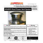
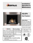
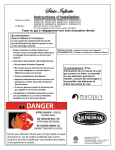
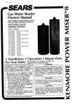
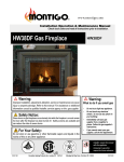
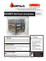
fire feature www.montigo.com Installation Operation & Maintenance Manual Check local codes and read all instructions prior to installation. BF-SeriesWall SS Gas Fireplace EDVWSPV Power Vent System Warning: Warning: Improper installation, adjustment, alteration, service or maintenance can cause injury or property damage. Refer to this manual. For assistance or additional information consult a qualified installer, service agency or the gas supplier. Safety Notice: Glass doors on gas fireplaces are extremely hot while the fireplace is on and remain hot even after the fireplace has been turned off. Safety screens are available and can reduce the risks of severe burns. Please keep children away from the fireplace at all times. For Your Safety: Do not store or use gasoline or other flammable vapors and liquids in the vicinity of this or any other appliance. XG1303 Canadian Heating Products Inc. Langley, BC V4W 4A EDVWSPV47 EDVWSPV58 What to do if you smell gas • • Do not try to light any appliance. Do not touch any electrical switch; do not use any phone in your building. • Immediately call your gas supplier from a neighbor's phone. Follow the gas supplier's instructions. • If you cannot reach your gas supplier, call the fire department. • Installer: Leave this manual with the appliance. • Consumer: Leave this manual for future reference. Montigo Del Ray Corp. Ferndale, WA 98248 062010 EDVWSPV Horizontal Power Vent System Warning: Read this manual before installing, operating or troubleshooting this appliance. Please retain this owner's manual for future reference. Safety Alert Key: • • • • • DANGER! Indicates a hazardous situation which, if not avoided will result in death or serious injury. WARNING! Indicates a hazardous situation which, if not avoided could result in death or serious injury. CAUTION! Indicates a hazardous situation which, if not avoided, could result in minor or moderate injury. NOTICE: Used to address practices not related to personal injury. Important: Used to address practices not related to personal injury. Table Of Contents Specifications Congratulations Safety Alert Key Table of Contents...................................................................... 2 Specifications................................................................ 2 Introduction................................................................................ 3 Dimensions.............................................................................4-5 Installation General Information...................................................... 6 Selecting and Installing the Fireplace......................... 6 Vent Installation............................................................ 6 Power Vent Installation............................................6 - 7 Wiring.......................................................................8 - 9 Warranty A. Termination Locations........................................... 11 B State of Massachusetts / Amendment.................. 12 Page 2 M2E068DF Manufacturer : EBM Germany Voltage: 110 Volts Frequency: 50 Hz Current draw: 1.41 Amp Power consumption: 155 W Speed: 2850 RPM Maximum air movement: 400 CFM at zero restriction Minimum air movement: 50CFM at 2.2" WC Protection: Thermal switch Bearings Ball bearings . ........................................................................ 10 Appendix Motor Model Number: Important: All dimensions, and design specifications are subject to approval upon quotation of fireplace and associated equipment. Part No. XG1303 - 120110 EDVWSPV Horizontal Power Vent System Introduction CAUTION! Due to its high operating temperatures, the appliance should be located in a well ventilated area / space. See the clearancespecifications on Page 8. Children and adults should be alerted to the hazards of the high surface temperature, which could cause burns or clothing ignition. Young children should be carefully supervised when they are in the same room as the appliance. Clothing or other flammable materials should not be placed on or near the appliance. Selecting and Installing the Fireplace When selecting a gas fireplace for use with the External Power Vent System, take into consideration the various requirements and limitations in the venting installation section for the following models: Models Equipped with Hot Surface Ignition (HSI) It is recommended that this system be used with a gas fireplace equipped with a Hot Surface Ignition System. Because there is not a pilot in this system, there is more flexibilty on venting requirements. For example downward vertical vet runs are possible with an HSI system, as outlined in the Venting Section. Models Equipped with Millivolt/ Standing Pilot General Information This installation guide covers installation of the External Power Vent System only. This system is designed to allow installation of gas fireplaces that cannot be done with a standard Direct Vent gas fireplace installation. If a standing pilot model must be used, then the millivot wiring harness must be installed, see the Wiring Section for more information. Also, downward vertical vet runs are not possible with a standing pilot system, as outlined in the Venting Section. Also, read through the fireplace's Installation Operation and Maintenance Instructions, as it must also be adhered to. Power Cord Harnesses: EPVH10 -10 foot power cord and harness EPVH20 -20 foot power cord and harness EPVH30 -30 foot power cord and harness EPVH40 -40 foot power cord and harness EPVH50 -50 foot power cord and harness EPVH60 -60 foot power cord and harness EPVH70 -70 foot power cord and harness EPVH80 -80 foot power cord and harness EPVH90 -90 foot power cord and harness EPVH100 -100 foot power cord and harness Before You Begin ■Minimum clearances 1” from vent to all combustible materials must be maintained. Clearances listed in the fireplace’s Installation Operation and Maintenance Instructions supersede this number. Part No. XG1303 - 120110 CAUTION: Ensure Perforated Air Holes in the New Pipe Adapter / Restrictor are not Covered when installing New Pipe Connection. CAUTION: When cold air enters the warmer building interior, primarily at the air intake end, condensation may occur on the exterior of the flex pipe. To limit this condensation, install insulation over the last twenty feet of flex pipe. Also, by sloping the last 20'-0" feet of flex pipe downward toward the exterior of the building, elimination of most of the condensation problems should occur. Ensure the termination is securely fastened, and sealed to the flex pipe. Fasten the termination to exterior of the building with water tight sealant and the appropriate fasteners. Page 3 EDVWSPV Horizontal Power Vent System Dimensions 11 1/16" 10 9/16" 11 1/16" 4 9 3/4" 9.0 9 3/4" REF. Dimensions EDVWSPV47. 14 1/16" 14 1/4" 12 5/16" 9 11/16" 4 12 1/8" 1 1/2" 4 9/16" 7 9 11/16" Dimensions EPVF47 mounting frame for EDVWSPV47. Page 4 Part No. XG1303 - 120110 EDVWSPV Horizontal Power Vent System Dimensions 10 9/16" 11 1/16" 11 1/16" 11 1/16" 9 3/4" 5 9.0 10 9/16" 9.0 5 Dimensions EDVWSPV58. 14 1/16" 14 1/4" 9 11/16" 12 5/16" 4 12 1/8" 1 1/2" 4 9/16" 8 9 11/16" Dimensions EPVF58 mounting frame for EDVWSPV58. Part No. XG1303 - 120110 Page 5 EDVWSPV Horizontal Power Vent System Installation Downward Vertical Venting (HSI Models Only) Venting Installation It is recommended that the External Power Vent System be used with a gas fireplace that is equipped with HSI. When installing the venting, the installation must adhere to the Vent Installation Section in the fireplace's Installation Operation and Maintenance Instructions, as well as the following guidelines: Downward venting installations are only possible with gas fireplaces equipped with Electronic or Hot Surface Ignition (HSI). H1 ■Ensure that the planned termination location is acceptable as shown in Appendix A. ■ Maximum allowed vent run is 100 feet. V D H H2 V Restrictor #1 Max V + H Max Elbows 80’f eet six 90 Restrictor #1 Max V1 + H1 + D + H2 Max Elbows 40 ’ feet six 90 Figure 3. Downward Venting Installations. Figure 1. Typical Venting Installations. Installing the Power Vent Multi-Elbow Installations Multi-elbow installations are possible up to a maximum of six 90° elbows. Elbow 6 V3 H3 Selecting A Termination Location Before installing the termination, ensure that the proper air flow restrictor is installed as shown on page 5, and check to ensure the planned termination location is acceptable. For a detailed illustration of allowed termination locations, see Appendix A. Installing the External PV Termination Step 1.Construct a frame for the termination opening to 12 1/2" x 12 1/2".3. Elbow 4 Elbow 5 H2 V2 12 ‰ Elbow 2 Elbow 3 H1 V1 Elbow 1 12 ‰ Restrictor #1 Max V1 + H1 + V2 + H2 + V3 + H3 80’ feet Figure 2. Multi-elbow Venting Installations. Page 6 Max Elbows six 90 Figure 4. Framing the Opening for Power Vent Step 2. Insert the Power Vent Rough-in Box as shown in Figure 5. Fasten the Box securely in place with Screws or nails, Figure 5. Apply exterior sheathing and finishing if required. (Figure 6). Part No. XG1303 - 120110 EDVWSPV Horizontal Power Vent System Installation Step 5. Framing Fasteners Securely fasten bottom Collar pan into the Rough-in frame using the existing hardware, (4-pcs). Tighten Strain Relief nut onto Strain relief. Step 6. Rough-in Frame Pull Power Vent Connector, (from behind) half-way through supplied hole in conduit mounting frame, and snap into place, (notches in two plastic wing clips. Orientation not critical). Strain Relief & tightened nut Power Vent Conduit Figure 5. Orientation, Placing the Power Vent Inner Box Conduit mounting frame Step 3. Next, remove the bottom collar and conduit mounting frame as shown Figure 6. (Place removed hardware in a handy location for re-assembly). Power Vent Connector Tightened hardware, 4-pcs. Figure 7. (Installing Conduit connector & conduit mounting frame) Step 7. Fasten Conduit mounting frame into place using existing hardware, (6-pcs). (Coil conduit in behind cover.) Figure 6. Installation of Rough-in Kit Installed Power Vent Connector Step 4. Insert the conduit from the Power Vent Module into the rough-in frame through the two top right entry holes. Remove the nut from the supplied strain relief and place as shown, Figure 7. Tightened hardware, 6-pcs. Strain Relief Power Vent Conduit Figure 8. (Assembled Rough-in Kit) Step 8. Strain Relief Nut Install the Power Vent Power / communication harness. Hold the Power Vent in close proximity of the assembled Rough-in Kit, and plug in the Power Vent communication / Power Cord. (Note the direction and orientation of the pins inside the Power Vent connector, snap together). (Figure 9). Figure 7. Installation of Power Vent Conduit Part No. XG1303 - 120110 Page 7 EDVWSPV Horizontal Power Vent System Installation Wiring Installation TOP of Power Vent, (Note Quantity of louvers). Note louver direction Connect the wiring to the external power vent termination as outlined in the previous section, and connect the wiring to the fireplace as outlined in the schematic below. Ensure that the proper clearances are maintaned for the wiring and conduit. ■ When installing the wiring it must never run above the vent run and it must be at least 1" clear of all venting. Vent Figure 9. (Installation of Power Vent communication harness) Cable Step 9. Install the Power Vent. Place the Power Vent into the Rough-in frame, aligning the Power Vent into final position. Ensure the Harness is placed down in the Rough-in box when placing the Power Vent. (Secure the Power Vent in Place with the supplied hardware). Tightened hardware, 4-pcs. 1" min. Figure 11. Conduit and Wiring Clearances. Wall Switch Power Vent EDVRP47 Pilot Honeywell SV9501M ECB005 PPO Box PVFCB Inside Fireplace Control Cable Installation for Vertical Termination EXPVH 10 - 100. 120V Figure 10. (Installation of Power Vent) Figure 12. Wiring Diagram for Power Vent System. Step 10. Completed installation. Figure 11. (Completed Installation of Power Vent) Page 8 WARNING: Montigo will not be held responsible for any water damage that may occur from not installing the equipment as specified by this document. Part No. XG1303 - 120110 EDVWSPV Horizontal Power Vent System Installation WARNING! If you do not follow these instructions exactly, a fire or explosion may result causing property damage, personal injury or loss of life. Figure 13. Standard ECB006 Wiring Schematic for Power Vent System. Part No. XG1303 - 120110 Page 9 EDVWSPV Horizontal Power Vent System Warranty The Warranty The Companies warrants the Montigo Gas Appliance to be free from defects in materials and workmanship at the time of manufacture. On the Montigo, there is a ten-year warranty on the firebox and its components, a five-year warranty on the main burner, and a one-year warranty on the pilot burner, gas control valve and fibre logs. Glass, plated/painted finishes, and refractory lining are exempt. Remedy And Exclusions The coverage of this Warranty is limited to all components of the Gas Appliance manufactured by The Companies. This Warranty only covers Montigo Gas Appliances installed in the United States or Canada. If the components of the Gas Appliance covered by this Warranty are found to be defective within the time frame stated (see The Companies right of investigation outlined below). The Companies will, at its option, replace or repair defective components of the Gas Appliance manufactured by The Companies at no charge, and will also pay for reasonable labour costs incurred in replacing or repairing components. If repair or replacement is not commercially practical, The Companies will, at its option, refund the purchase price of the Montigo Gas Appliance. This Warranty covers only parts and labour as provided above. In no case shall The Companies be responsible for materials, components, or construction which are not manufactured or supplied by The Companies, or for the labour necessary to install, repair or remove such materials, components or construction. All replacement or repair components will be shipped F.O.B. the nearest The Companies factory. Qualifications To The Warranty The Gas Appliance Warranty outlined above is further subject to the following qualifications: (1) The Gas Appliance must be installed in accordance with The Companies installation instructions and local building codes. The Warranty on this Montigo Gas Appliance covers only the component parts manufactured by The Companies. The use of components manufactured by others with this Montigo Gas Appliance could create serious safety hazards, may result in the denial of certification by recognized national safety agencies, and could be in violation of local building codes. This warranty does not cover any damages occurring from the use of any components not manufactured or supplied by The Companies (2) The Montigo Gas Appliance must be subjected to normal use. The Gas Appliances are designed to burn gas only. Burning conventional fireplace fuels such as wood, coal or any other solid fuel will cause damage to the Gas Appliance, will produce excessive temperatures and will result in a fire hazard. Limitations On Liability It is expressly agreed and understood that The Companies sole obligation, and purchaser's exclusive remedy under this Warranty, under any other warranty, expressed or implied, or in contract, tort or otherwise, shall be limited to replacement, repair, or refund, as specified above. In no event shall The Companies be responsible for any incidental or consequential damages caused by defects in its products, whether such damage occurs or is discovered before or after replacement or repair, and whether or not such damage is caused by The Companies negligence. Some states do not allow the exclusion or limitation of incidental or consequential damages, so the above limitation or exclusion may not apply to you. The duration of any implied warranty with respect to this Montigo Gas Appliance is limited to the duration of the foregoing warranty. Some states do not allow limitation on how long an implied warranty lasts, so the above may not apply to you. Investigation Of Claims Against Warranty The Companies reserves the right to investigate any and all claims against this Warranty and to decide upon method of settlement. The Companies Are Not Responsible For Work Done Without Written Consent The Companies shall in no event be responsible for any warranty work done without first obtaining The Companies written consent. Dealers Have No Authority To Alter This Warranty The Companies employees and dealers have no authority to make any warranties nor to authorize any remedies in addition to or inconsistent with those stated above. How To Register A Claim Against Warranty In order for any claim under this Warranty to be valid, The Companies must be notified of the claimed defect in writing or by telephone, as soon as reasonably possible after the defect is discovered. Claims against this Warranty in writing should include the date of installation, and a description of the defect. Other Rights This Warranty gives you specific legal rights, and you may also have other rights which vary from state to state. NOTE: The Companies as stated above refer to - Canadian Heating Products Inc. and/or Montigo Del Ray Corp. Canadian Heating Products Inc. and/or Montigo DelRay Corp. reserves the right to make changes at any time, without notice, in design, materials, specifications, prices and also to discontinue colors, styles and products. Page 10 Part No. XG1303 - 120110 EDVWSPV Horizontal Power Vent System Appendix A - Termination Locations A = clearance to the termination frame above grade, veranda, porch, deck, or balcony [30 inches (75 cm) minimum] N= B = clearance to door, or sides and top of window, that may be opened [30 inches (75 cm) minimum for appliances. P = clearance under veranda, porch, deck, or balcony [30 inches (75 cm) minimum‡ to non-combustibles] [30 inches (75 cm) minimum‡ to combustibles] C = clearance to bottom of window that may be opened horizontally [36 inches (92 cm) minimum for appliances. Q = clearance above a roof [24 inches (61 cm) minimum] D = no clearance to permanently closed window when installed with approved glass penetration termination S = clearance from corner in recessed location [30 inches (75 cm) minimum] E = clearance to permanently closed window [30 inches 75 cm recommended to prevent condensation on window] F= G= distance of [30 inches 75 cm] from the centreline of the termination [30 inches (75 cm) minimum] [30 inches (75 cm) minimum to combustibles] R = clearance to adjacent walls and neighboring buildings [30 inches (75 cm) minimum] T= clearance to inside corner [30 inches (75 cm) minimum] J= * not to be installed above a meter/regulator assembly within 40" (103 cm) horizontally from the centreline of the regulator K = clearance to service regulator vent outlet [3 feet minimum in the United States] [*6 feet (1.8 m) minimum in Canada] L= maximum depth in recessed location [48 inches (122 cm) minimum] U = minimum width for back wall of recessed location [60 inches (150 cm) minimum] V = [30 inches (75 cm) minimum] horizontal clearance between the frames of two terminations that are level. W = horizontal clearance between the frames of two terminations that are not level. [30 inches (75 cm) minimum] † a vent shall not terminate directly above a sidewalk or paved driveway which is located between two single family dwellings and serves both dwellings ‡ only permitted if veranda, porch, deck, or balcony has an open side that is equal to or greater than the depth of the enclosed area H = clearance to outside corner [30 inches (75 cm) minimum] I= † clearance above paved sidewalk or a paved driveway located on public property [*7 feet (2.1 m) minimum] * require different clearance. clearance to non-mechanical air supply inlet to building or the combustion air inlet to any other appliance [16 inches (41 cm) minimum for appliances ≤100 000 BTU/H (30kW)] M = clearance to mechanical air supply inlet [*6 feet (1.8 m) minimum] Part No. XG1303 - 120110 Page 11 EDVWSPV Horizontal Power Vent System Appendix A - Termination Locations cont'd. EDVWSPV58 Horizontal Power Vent Detail Eaves / Overhang Wall 30”Min. “H” & “I” 30”Min. “ F” & “G” 30” (75cm) Min. “V” Front View Page 12 Part No. XG1303 - 120110 EDVWSPV Horizontal Power Vent System Appendix B - State of Massachusetts Amendment (Gas Fireplace / Equipment sold in the State of Massachusetts) 5.08: Modifications to NFPA-54, Chapter 10 (1) Revise NFPA-54 section 10.5.4.2 by adding a second exception as follows: Existing chimneys shall be permitted to have their use continued when a gas conversion burner is installed, and shall be equipped with a manually reset device that will automatically shut off the gas to the burner in the event of a sustained back-draft. (2) Revise 10.8.3 by adding the following additional requirements: (a) For all side wall horizontally vented gas fueled equipment installed in every dwelling, building or structure used in whole or in part for residential purposes, including those owned or operated by the Commonwealth and where the side wall exhaust vent termination is less than seven (7) feet above finished grade in the area of the venting, including but not limited to decks and porches, the following requirements shall be satisfied: 1. INSTALLATION OF CARBON MONOXIDE DETECTORS. At the time of installation of the side wall horizontal vented gas fueled equipment, the installing plumber or gas fitter shall observe that a hard wired carbon monoxide detector with an alarm and battery back-up is installed on the floor level where the gas equipment is to be installed. In addition, the installing plumber or gas fitter shall observe that a battery operated or hard wired carbon monoxide detector with an alarm is installed on each additional level of the dwelling, building or structure served by the side wall horizontal vented gas fueled equipment. It shall be the responsibility of the property owner to secure the services of qualified licensed professionals for the installation of hard wired carbon monoxide detectors a. In the event that the side wall horizontally vented gas fueled equipment is installed in a crawl space or an attic, the hard wired carbon monoxide detector with alarm and battery back-up may be installed on the next adjacent floor level. b. In the event that the requirements of this subdivision can not be met at the time of completion of installation, the owner shall have a period of thirty (30) days to comply with the above requirements; provided, however, that during said thirty (30) day period, a battery operated carbon monoxide detector with an alarm shall be installed. 2. APPROVED CARBON MONOXIDE DETECTORS. Each carbon monoxide detector as required in accordance with the above provisions shall comply with NFPA 720 and be ANSI/UL 2034 listed and IAS certified. 3. SIGNAGE. A metal or plastic identification plate shall be permanently mounted to the exterior of the building at a minimum height of eight (8) feet above grade directly in line with the exhaust vent terminal for the horizontally vented gas fueled heating appliance or equipment. The sign shall read, in print size no less than one-half (1/2) inch in size, “GAS VENT DIRECTLY BELOW. KEEP CLEAR OF ALL OBSTRUCTIONS”. 4. INSPECTION. The state or local gas inspector of the side wall horizontally vented gas fueled equipment shall not approve the installation unless, upon inspection, the inspector observes carbon monoxide detectors and signage installed in accordance with the provisions of 248 CMR 5.08(2)(a)1 through 4. (b) EXEMPTIONS: The following equipment is exempt from 248 CMR 5.08(2)(a)1 through 4: 1. The equipment listed in Chapter 10 entitled “Equipment Not Required To Be Vented” in the most current edition of NFPA 54 as adopted by the Board; and 2. Product Approved side wall horizontally vented gas fueled equipment installed in a room or structure separate from the dwelling, building or structure used in whole or in part for residential purposes. (c) MANUFACTURER REQUIREMENTS - GAS EQUIPMENT VENTING SYSTEM PROVIDED. When the manufacturer of Product Approved side wall horizontally vented gas equipment provides a venting system design or venting system components with the equipment, the instructions provided by the manufacturer for installation of the equipment and the venting system shall include: 1. Detailed instructions for the installation of the venting system design or the venting system components; and 2. A complete parts list for the venting system design or venting system. (d) MANUFACTURER REQUIREMENTS - GAS EQUIPMENT VENTING SYSTEM NOT PROVIDED. When the manufacturer of a Product Approved side wall horizontally vented gas fueled equipment does not provide the parts for venting the flue gases, but identifies “special venting systems”, the following requirements shall be satisfied by the manufacturer: 1. The referenced “special venting system” instructions shall be included with the appliance or equipment installation instructions; and 2. The “special venting systems” shall be Product Approved by the Board, and the instructions for that system shall include a parts list and detailed installation instructions. (e) A copy of all installation instructions for all Product Approved side wall horizontally vented gas fueled equipment, all venting instructions, all parts lists for venting instructions, and/or all venting design instructions shall remain with the appliance or equipment at the completion of the installation. (3) After NFPA-54 section 10.10.4.2 add a new section 10.10.4.3 as follows: When more than four gas appliances are to be vented through a common gas vent or common horizontal vent manifold, a plan of the proposed vent installation shall be submitted to the Inspector and the serving gas supplier for review and approval. Extraction from: Massachusets Rules and Regulations 5.00: Amendments To 2002 Edition Of ANSI Z223.1-NFPA-54 Part No. XG1303 - 120110 Page 13 EDVWSPV Horizontal Power Vent System Notes Page 14 Part No. XG1303 - 120110 EDVWSPV Horizontal Power Vent System Notes Part No. XG1303 - 120110 Page 15 fire feature www.montigo.com XG1303 - 062010 Canadian Heating Products Inc. Langley, BC V4W 4A1 Montigo Del Ray Corp. Ferndale, WA 98248