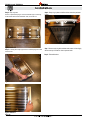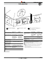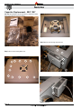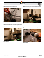
1
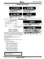
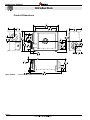
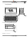
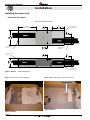
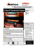
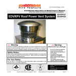
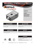
Installation & Maintenance Manual
PVHIN58-300 with
TMHIN58-40
5/8 Inline Power
Vent with Flush
Louvered
Termination
WARNING
If the information in these instructions is not followed exactly, a fire or explosion
may result causing property damage, personal injury or death.
NOTICE
Installer: Leave this manual with the appliance.
Consumer: Retain this manual for future reference.
DANGER
Blank
IF YOU SMELL GAS
Do not try to light any appliance.
Do not touch any electrical switch; do not use any phone in your building.
Immediately call your gas supplier from a neighbor's phone. Follow the gas
supplier's instructions.
If you cannot reach your gas supplier, call the fire department.
Blank
Flammable materials
Explosion risk
Blank
Flammable materials
Explosion risk
General Warning
Laser Radiation
Toxic
Corrosive
Danger overhead crane
Toxic
Corrosive
Fork lift trucks
Danger overhead crane
Fork lift trucks
Biohazard
Oxidising
Hot surface
Danger of entrapment
Toxic
Corrosive
Danger overhead crane
Fork lift trucks
Biohazard
Oxidising
Hot surface
Danger of entrapment
Danger of death
Cutting
High temperatures
Glass hazard
Danger of suffocation
Hot surface
Danger of entrapment
Danger of death
Glass hazard
Danger of suffocation
Flammable materials
Explosion risk
General Warning
Laser Radiation
Irritant
Slippery floor
Watch your step
NOTICE
High voltage
High voltage
Danger of death
High voltage
This power vent is approved for use with Montigo fireplaces only and is certified to
ANSI Z21.50 / CSA 2.22 vented gas fireplace standard along with the fireplace.
Blank
Laser Radiation
Biohazard
Irritant
Slippery floor
Watch your step
Cutting
Gas bottles
Watch for
falling objects
Explosion
risk
Electricity
Danger for cutter
Entrapment hazard
Battery hazard
Flammable materials
General Warning
Toxic
Corrosive
Danger overhead crane
Fork lift trucks
High voltage
Irritant
Slippery floor
Watch your step
Oxidising
Cutting
High temperatures
Glass hazard
Danger of suffocation
Gas bottles
Watch for
falling
objectsfield
Strong
magnetic
Electricity
Danger for cutter
Entrapment hazard
Battery hazard
Rotating parts
Low temperature
Optical radiation
Laser Radiation
Biohazard
Non ionizing
radiation
Oxidising
Radiation
General Warning
Hot surface
Hazardous to the
Environment
Danger of entrapment
Danger of harming
your hands
Danger of death
Gas bottles
Watch for
falling objects
Strong magnetic field
Electricity
Danger for cutter
Optical radiation
High temperatures
Rotating parts
Entrapment hazard
Battery hazard
Non ionizing
radiation
Radiation
Hazardous to the
Environment
Danger of harming
your hands
Irritant
Slippery floor
Watch your step
Cutting
High temperatures
Glass hazard
Danger of suffocation
Low temperature
Strong magnetic field
Optical radiation
Non ionizing
radiation
Radiation
Hazardous to the
Environment
Danger of harming
your hands
Gas bottles
Watch for
falling objects
Electricity
Danger for cutter
Entrapment hazard
Battery hazard
Rotating parts
Low temperature
Rotating parts
NOTICE
PVHIN58-300 and TMHIN58-40 are approved for use with Montigo R320, R320-ST,
R420, R420-ST, and RP620.
XG0521
Canadian Heating Products Inc. Langley, BC V4W 4A1 | Montigo Del Ray Corp. Ferndale, WA 98248
111214
PVHIN58-300 with TMHIN58-40
Table of Contents
Instruction Manual Contents
Specifications������������������������������������������������������������������������������������������������������������������������������������������������������������������������������������������������������� 3
Before Your Begin������������������������������������������������������������������������������������������������������������������������������������������������������������������������������������������������� 3
General Information��������������������������������������������������������������������������������������������������������������������������������������������������������������������������������������������� 3
Power Cord Harnesses: ����������������������������������������������������������������������������������������������������������������������������������������������������������������������������������������������������3
Product Dimensions��������������������������������������������������������������������������������������������������������������������������������������������������������������������������������������������� 4
Installing the power vent������������������������������������������������������������������������������������������������������������������������������������������������������������������������������������� 6
Power Vent Clearances��������������������������������������������������������������������������������������������������������������������������������������������������������������������������������������������������������������6
Conduit and Wiring Clearances��������������������������������������������������������������������������������������������������������������������������������������������������������������������������������������������������9
How to use Diluter Collar����������������������������������������������������������������������������������������������������������������������������������������������������������������������������������� 10
How to Open and Set the Diluter Collar������������������������������������������������������������������������������������������������������������������������������������������������������������������������������������10
Power Vent Wiring ����������������������������������������������������������������������������������������������������������������������������������������������������������������������������������������������11
Installing the TMHIN58-40 Termination ����������������������������������������������������������������������������������������������������������������������������������������������������������� 12
Termination clearances����������������������������������������������������������������������������������������������������������������������������������������������������������������������������������������������������������������������������������� 12
Capacitor Replacement - REC 1257����������������������������������������������������������������������������������������������������������������������������������������������������������������� 16
Motor and Capacitor Replacement - REC 1258����������������������������������������������������������������������������������������������������������������������������������������������� 20
Appendix A: Warranty ��������������������������������������������������������������������������������������������������������������������������������������������������������������������������������������������������������������24
Appendix B: State of Massachusetts����������������������������������������������������������������������������������������������������������������������������������������������������������������������������������������25
Page 2
XG0521 - 111214
PVHIN58-300 with TMHIN48-40
Safety Alert Key
Specifications
Introduction
Pipe Dimensions PVHIN58-300 ............. 5"/8"
Pipe Dimensions TMHIN58-40 ............... 5"/8"
Maximum Airflow: .......................... 300 CFM
Speed: ........................................... 2700 RPM
Power:............................................. Connect to fireplace control box
............................................. Refer to fireplace rating plate
Before Your Begin
General Information
This installation guide covers installation of the External Power Vent
System only. This system is designed to allow installation of gas fireplaces
that cannot be done with a standard Direct Vent gas fireplace installation.
Only for use on R-Series, R-Series See-Through and RP-Series that
uses the 5/8 venting system.
ONLY USE WITH APPROVED FIREPLACES - see fireplace installation manual.
Read through the fireplace's installation & maintenance manual, as it
must also be adhered to.
Power Cord Harnesses:
EPVH10 - 10 foot power cord and harness
EPVH20 - 20 foot power cord and harness
EPVH30 - 30 foot power cord and harness
EPVH40 - 40 foot power cord and harness
EPVH50 - 50 foot power cord and harness
EPVH60 - 60 foot power cord and harness
EPVH70 - 70 foot power cord and harness
EPVH80 - 80 foot power cord and harness
EPVH90 - 90 foot power cord and harness
EPVH100 -100 foot power cord and harness
For vent configurations and power vent locations,
refer to fireplace manual. XG0521 - 111214
Page 3
PVHIN58-300 with TMHIN58-40
Introduction
Product Dimensions
5
"
8
703
27
7"
178
4"
102
8"
202
22"
559
1
"
4
591
23
13"
330
5"
126
23"
584
8"
202
7
"
8
532
20
7
"
8
124
4
5
7 "
8
193
5"
126
3
"
8
87
7"
178
3
1"
25
14"
356
7"
178
Figure 1 Section2.
Page 4
2"
50
7
"
8
861
33
PVHIN58-300 Inline power vent unit dimensions
XG0521 - 111214
PVHIN58-300 with TMHIN58-40
Introduction
Product Dimensions
Unit Dimensions
1
"
4
996
39
3
"
4
348
1
12 "
2
318
1
10 "
4
260
13
5
"
8
932
36
9"
227
8"
202
5"
126
3
"
4
19
1
"
2
1003
39
3
"
8
316
3
"
8
59
2
14"
354
12
7
"
8
963
37
Figure 2 Section2.
TMHIN58-40 termination unit dimensions (without vanity ring)
5
"
8
1056
41
5
"
8
1005
39
14"
356
16"
406
1
"
2
13
Figure 3 Section2.
XG0521 - 111214
Vanity ring dimensions.
Page 5
PVHIN58-300 with TMHIN58-40
Installation
Installing the power vent
Power Vent Clearances
Non-Combustible Zone
7' minimum
(open one side)
7
"
8
633
Min
24
2"
51
Min
20"
508
Min
This end can
be closed off
12"
305
Min
Vent Pipe
Vent Pipe
2"
51
Min
This end must
be open
2"
51
This end must
be open
15"
381
Min
Standard Vent
Clearances
12"
305
Vent Pipe
Vent Pipe
This end can
be closed off
Figure 1. Section 3 PVHIN58-300 Clearances
Step 1. Unpack the power vent from supplied box.
Step 2. Attach mounting feet by removing screws and tape.
Mounting Feet
Figure 2. Section 3 Page 6
Figure 3. Section 3 XG0521 - 111214
PVHIN58-300 with TMHIN58-40
Installation
Step 4. See Fireplace Manual for approved vent runs. Make sure you have
the correct orientation of power vent. One end must face the fireplace and
one end must face the termination.
Figure 4. Section 3 Figure 6. Section 3 Figure 5. Section 3 Figure 7. Section 3 Step 3. Power vent cannot be installed closer than 7 feet of venting to the
appliance. This is the case whether vertical, horizontal or any combination.
Min. 7 feet of pipe between fireplace
and power vent
PVHIN58-300
XG0521 - 111214
Page 7
PVHIN58-300 with TMHIN58-40
Installation
Step 5. Remove two screws securing electrical plate.
Figure 8. Section 3 Step 7. Take electrical harness [EPVH-10-100] that will communicate with
the power vent, and attach the strain relief for it to the electrical plate. Tighten
the nut on the strain relief.
Figure 10. Section 3 Step 6. Remove power vent cable from inside component cover.
Figure 11. Section 3 Figure 9. Section 3 Page 8
XG0521 - 111214
PVHIN58-300 with TMHIN58-40
Installation
Step 8. Attach the power cable from the power vent to the control cable.
Conduit and Wiring Clearances
Connect the power vent harness as outlined. Connect
the wiring to the fireplace as outlined in the schematic
showin in Figure 14 Section 3. Ensure that the proper
clearances are maintained for the wiring and conduit.
When installing the wiring, it must never run above the
vent pipe and it must be at lest 1" clear of all venting and
other hot surfaces.
1” Clearance
Figure 12. Section 3 Wire
Figure 14. Section 3 Step 9. Push all excess cable back into the component cover. Screw electrical plate back on the power vent.
Figure 13. Section 3 XG0521 - 111214
Page 9
PVHIN58-300 with TMHIN58-40
Installation
How to use Diluter Collar
The PVHIN58-300 is equipped with a built-in diluter collar to allow
air to bypass the fireplace. This results in slower air movement in the
fireplace while still allowing for increased air flow through the power
vent and termination, which keeps them cooler.The PVHIN58-300 is
shipped with the diluter collar completely closed.
Note: When using the PVHIN58-300 with the RP620, you may not
be able to open the diluter collar depending on the vent run. This is
not such an issue, as the RP620 has its own bypass built into it which
allows for a slower looking flame.
Step 3. Turn your fireplace on.
Likely this diluter collar will be too open to engage the air proving
switch.
Step 4. Turn the diluter collar screw slowly counter clockwise until the air
proving switch is activated.
The diluter collar is now set to the minimum adjustment to allow the
fireplace to operate.
If you have wind issues, or if the fireplace goes out from time-to-time,
close the diluter collar more to allow a higher air proving switch signal.
How to Open and Set the Diluter Collar
Step 1. Set power vent speed on the control box to full speed
Step 2. Open the diluter collar 100% by turning the diluter collar adjustment screw clockwise until the screw won't turn anymore.
As you turn the screw clockwise, the diluter collar plate will slide
along the rails until it stops against the inside of the power vent
shell.
Diluter
Adjustment
Screw
Diluter Collar Plate
Figure1. Section 4 Page 10
Cutaway view
of Outer Box
Diluter Operation
XG0521 - 111214
PVHFL58-300 & PVHFL510-300 Horizontal Power Vent
Service
Power Vent Wiring
Power Vent Wiring
6 PIN MOLEX
CONNECTOR
GREEN
BLUE
BLACK
BROWN
C
BLACK
WHITE
KEY WAY
Figure 1 Section 5. Power Vent Wiring
XG0519 - 070714
Page 11
PVHIN58-300 with TMHIN58-40
Installation
Installing the TMHIN58-40 Termination
Termination clearances
Minimum Combustible Clearances
3
"
4
960
37
Minimum combustible
clearances
1
"
2
166
3
"
4
223
6
1
"
4
57
2
1
"
4
310
12
8
1
"
4
7
Termination
Minimum combustible
clearances
1
"
4
7
40"
1016
1
"
2
367
14
Figure 2 Section 5. Step 1. Unpackaging the termination.
Figure 3 Section 5. Page 12
XG0521 - 111214
PVHIN58-300 with TMHIN58-40
Installation
Step 2. If doing a concrete install, the termination has two adjustable mounting feet on the sides of the termination.
Concrete Wall
Concrete Anchors
Fasteners
Mounting Feet
Figure 4 Section 5. Step 3. If doing a combustible frame install, remove the concrete mounting feet and install as shown in Figure 5 Section 5.
3
"
4
960
Min
37
Wood Frame
Termination
Body
1
"
4
310
Min
12
Louver Pack
Wood Screws (14x)
Figure 5 Section 5. XG0521 - 111214
Page 13
PVHIN58-300 with TMHIN58-40
Installation
Step 4. Vanity ring install.
There is an optional vanity ring to cover the unfinished edges of rock facing
on the exterior wall around the termination. First, remove the door.
Step 6. Clamp ring in place and drill out holes around the perimeter
of door.
Figure 8 Section 5. Figure 9 Section 5. Step 5. To install, place vanity ring around door until vanity ring is flush with
surface of door.
Step 7. Secure vanity ring with stainless steel screws or rivets. Apply
silicone over top of screws or rivets to prevent leaks.
Step 8. Reinstall the door.
Figure 6 Section 5. Figure 7 Section 5. Page 14
XG0521 - 111214
PVHIN58-300 with TMHIN58-40
Introduction
PVHIN58-300
E
INSID ETAIL
ER D
CORN
G
v
H
A
D
E
V
B
L
V
F
B
B
C
v
FIXED
ED
CLOS
v
OPER
FIXED
ED
CLOS
ABLE
v
OPER
ABLE
B
I
M
X
v
X
v
A
v
K
J
B
V VENTER TERMINAL
Canadian Installations
X AIR SUPPLY INLET
1
US Installations
2
A= Clearance above grade, veranda,
porch, deck, or balcony
12 in (30 cm)
12 in (30 cm)
B= Clearance to window or door that
may be opened
6 in (15 cm) for appliances <
10,000 Btuh (3 kW), 12 in
(30 cm) for appliances >
10,000 Btuh (3 kW) and <
100,000 Btuh (30 kW), 36 in
(91 cm) for appliances >
100,000 Btuh (30 kW)
6 in (15 cm) for appliances <
10,000 Btuh (3 kW), 9 in
(23 cm) for appliances >
10,000 Btuh (3 kW) and <
50,000 Btuh (15 kW), 12 in
(30 cm) for appliances >
50,000 Btuh (15 kW)
C= Clearance to permently closed
window
D= Vertical clearance to ventilated
soffit located above the terminal within
a horizontal distance of 2 feet (61 cm)
from the center line of the terminal
E= Clearance to unventilated soffit
F= Clearance to outside corner
G= Clearance to inside corner
B
B
See Fireplace Installation Guide
See Fireplace Installation Guide
*
*
See Fireplace Installation Guide
H= Clearance to each side of center
line extended above meter/regulator
assembly
3 ft (91 cm) within a height 15
ft. (4.5 m) above the meter/
regulator assembly
I= Clearance to service regulator
vent outlet
3 ft (91 cm)
*
AREA WHERE TERMINAL IS
NOT PERMITTED
Canadian Installations
1
US Installations
2
J= Clearance to nonmechanical air
supply inlet to building or the
combustion air inlet to any other
appliance
6in (15 cm) for appliances <
10,000 Btuh (3 kW), 12 in (30
cm) for appliances > 10,000
Btuh (3 kW) and < 100,000
Btuh (30 kW), 36 in (91 cm)
for appliances > 100,000
Btuh (30 kW)
6in (15 cm) for appliances <
10,000 Btuh (3 kW), 9 in (23
cm) for appliances > 10,000
Btuh (3 kW) and < 50,000
Btuh (15 kW), 12 in (30 cm)
for appliances > 50,000 Btuh
(15 kW)
K= Clearance to a mechanical air
supply inlet
6 ft (1.83 m)
3 ft (91 cm) above if within 10
ft (3 m) horizontally
L= Clearance above paved sidewalk
7 ft (2.13 m)
*
or paved driveway located on
public property
M= Clearance under veranda porch
12 in (30 cm)
*
deck, or balcony
1 In accordance with the current CSA B149.1, Natural Gas and Propane Installation Code
2 In accordance with the current ANSI Z223.1/NFPA 54, National Fuel Gas Code
A vent shall not terminate directly above a sidewalk or paved driveway that is located between two
single family dwellings and serves both dwellings.
Permitted only if veranda, porch, deck, or balcony is fully open on a minimum of two sides beneath
the floor.
* For clearances not specified in ANSI Z223.1/NFPA or CSA B149.1, one of the following shall be
indicated
a) A minimum clearance value determined by testing in accordance with section 2.23.5, or;
b) A reference to the following footnote:
"Clearance in accordance with local installation codes and the requirements of the gas supplier"
*
Figure 10 Section 5. XG0521 - 111214
Page 15
PVHIN58-300 with TMHIN58-40
Service
Capacitor Replacement - REC 1257
REC 1257 Note: Maintenance must be preformed by a qualified and certified
person. Turn off the power and gas to fireplace.
Figure 3. Section 6 Step 2. Remove screws securing component cover.
Figure 1. Section 6
Step 1. Remove screws securing blower cover.
Figure 4. Section 6 Figure 2. Section 6 Figure 5. Section 6 Page 16
XG0521 - 111214
PVHIN58-300 with TMHIN58-40
Service
Step 3. Cut zap strap securing wires together in bundle.
Step 5. Cut off small bell connector connecting brown wire from blower and
the other black wire from capacitor.
Figure 6. Section 6 Figure 8. Section 6 Step 4. Cut off large bell connector connecting white fibre wire from power
cable, black wire from blower and one black wire from capacitor. Cut as little
as possible, there is not much space.
Step 6. Unscrew old capacitor and discard. Secure new capacitor in its
place.
Figure 7. Section 6 XG0521 - 111214
Figure 9. Section 6 Page 17
PVHIN58-300 with TMHIN58-40
Service
Step 7. Strip about 3/8" to 1/2" off all wire that was cut.
Figure 10. Section 6 Step 8. Twist brown wire from blower together with the other black wire from
capacitor. Using small bell connector supplied, crimp wires together.
Step 9. Twist white fibre wire from power cord together with black wire from
blower and one black wire from capacitor. Using large bell connector sup-
Figure 12. Section 6 Step 10. Using suppied zap strap, secure wire bundles together.
Figure 11. Section 6 Figure 13. Section 6 Page 18
XG0521 - 111214
PVHIN58-300 with TMHIN58-40
Service
Step 11. Reinstall component cover.
Figure 14. Section 6 Step 13. Turn power back on and check blower rotation is counter clock-
wise.
Figure 16. Section 6 Step 12. Reinstall blower cover.
Figure 15. Section 6 XG0521 - 111214
Page 19
PVHIN58-300 with TMHIN58-40
Service
Motor and Capacitor Replacement - REC 1258
REC 1258 Note: Maintenance must be preformed by qualified personnel/
electrician. Turn off the gas / power.
Figure 3. Section 7
Figure 1. Section 7
Step 2. Remove screws securing component cover.
Step 1. Remove screws securing blower cover.
Figure 4. Section 7
Figure 10a.
Figure 2. Section 7
Figure 5. Section 7
Page 20
XG0521 - 111214
PVHIN58-300 with TMHIN58-40
Service
Step 3. Unplug capacitor / blower assembly from power vent power cable.
Figure 6. Section 7
Step 5. Unscrew capacitor from mounting point.
Figure 8. Section 7
Step 6. Unscrew blower from power vent.
Step 4. Unscrew black zap strap anchor / ground wire.
Figure 7. Section 7
Figure 9. Section 7
Step 7. Remove capacitor / blower assembly and discard.
*If under warranty, contact Montigo to return for credit.
XG0521 - 111214
Page 21
PVHIN58-300 with TMHIN58-40
Service
Step 8. Secure blower to Power Vent using supplied screws and star washers. Make sure wire is close to component mounting box.
Step 9. Secure capacitor component mounting bracket.
Figure 12. Section 7
Figure 10. Section 7
Step 10. Secure wires and ground screw to Power Vent using supplied black
zap strap anchor.
Figure 11. Section 7
Figure 13. Section 7
Page 22
XG0521 - 111214
PVHIN58-300 with TMHIN58-40
Service
Step 11. Plug capacitor / blower assembly into Power Vent power
Step 13. Reinstall blower cover.
Figure 14. Section 7
Figure 16. Section 7
cord.
Step 14. Turn on power.
Step 12. Reinstall component cover.
Step 15. Check blower rotation is counter clockwise.
Figure 15. Section 7
Figure 17. Section 7
XG0521 - 111214
Page 23
PVHIN58-300 with TMHIN58-40
Appendix
Appendix A: Warranty
The Warranty
The Companies warrants the Montigo Gas Appliance to be free from defects in materials and workmanship at the time of manufacture. On the Montigo fireplace,
there is a ten-year warranty on the firebox and its components, a five-year warranty on the main burner and pilot burner, and a one-year warranty on the gas control
valve, fibre logs and Power Vent Module. The Glass, plated / painted finishes, and refractory lining are exempt from the warranty.
Remedy And Exclusions
The coverage of this Warranty is limited to all components of the Gas Appliance manufactured by The Companies.
This Warranty only covers Montigo Gas Appliances installed in the United States or Canada.
If the components of the Gas Appliance covered by this Warranty are found to be defective within the time frame stated (see The Companies right of investigation
outlined below). The Companies will, at its option, replace or repair defective components of the Gas Appliance manufactured by The Companies at no charge,
and will also pay for reasonable labour costs incurred in replacing or repairing components. If repair or replacement is not commercially practical, The Companies
will, at its option, refund the purchase price of the Montigo Gas Appliance.
This Warranty covers only parts and labour as provided above. In no case shall The Companies be responsible for materials, components, or construction which
are not manufactured or supplied by The Companies, or for the labour necessary to install, repair or remove such materials, components or construction. All
replacement or repair components will be shipped F.O.B. the nearest The Companies factory.
Qualifications To The Warranty
The Gas Appliance Warranty outlined above is further subject to the following qualifications:
(1) The Gas Appliance must be installed in accordance with The Companies installation instructions and local building codes. The Warranty on this Montigo
Gas Appliance covers only the component parts manufactured by The Companies. The use of components manufactured by others with this Montigo Gas
Appliance could create serious safety hazards, may result in the denial of certification by recognized national safety agencies, and could be in violation of
local building codes. This warranty does not cover any damages occurring from the use of any components not manufactured or supplied by The Companies
(2) The Montigo Gas Appliance must be subjected to normal use. The Gas Appliances are designed to burn gas only. Burning conventional fireplace fuels such
as wood, coal or any other solid fuel will cause damage to the Gas Appliance, will produce excessive temperatures and will result in a fire hazard.
Limitations On Liability
It is expressly agreed and understood that The Companies sole obligation, and purchaser's exclusive remedy under this Warranty, under any other warranty,
expressed or implied, or in contract, tort or otherwise, shall be limited to replacement, repair, or refund, as specified above.
In no event shall The Companies be responsible for any incidental or consequential damages caused by defects in its products, whether such damage occurs
or is discovered before or after replacement or repair, and whether or not such damage is caused by The Companies negligence. Some states do not allow the
exclusion or limitation of incidental or consequential damages, so the above limitation or exclusion may not apply to you. The duration of any implied warranty
with respect to this Montigo Gas Appliance is limited to the duration of the foregoing warranty. Some states do not allow limitation on how long an implied warranty
lasts, so the above may not apply to you.
Investigation Of Claims Against Warranty
The Companies reserves the right to investigate any and all claims against this Warranty and to decide upon method of settlement.
The Companies Are Not Responsible For Work Done Without Written Consent
The Companies shall in no event be responsible for any warranty work done without first obtaining The Companies written consent.
Dealers Have No Authority To Alter This Warranty
The Companies employees and dealers have no authority to make any warranties nor to authorize any remedies in addition to or inconsistent with those stated above.
How To Register A Claim Against Warranty
In order for any claim under this Warranty to be valid, The Companies must be notified of the claimed defect in writing or by telephone, as soon as reasonably
possible after the defect is discovered. Claims against this Warranty in writing should include the date of installation, and a description of the defect.
Other Rights
This Warranty gives you specific legal rights, and you may also have other rights which vary from state to state.
NOTE:
The Companies as stated above refer to - Canadian Heating Products Inc. and/or Montigo Del Ray Corp.
Canadian Heating Products Inc. and/or Montigo DelRay Corp. reserves the right to make changes at any time, without notice, in design, materials,
specifications, prices and also to discontinue colors, styles and products.
Page 24
XG0521 - 111214
PVHIN58-300 with TMHIN58-40
Appendix
Appendix B: State of Massachusetts
Amendment
(Gas Fireplace / Equipment sold in the State of Massachusetts)
5.08: Modifications to NFPA-54, Chapter 10
(1) Revise NFPA-54 section 10.5.4.2 by adding a second exception as follows:
Existing chimneys shall be permitted to have their use continued when a gas conversion burner is installed, and shall be equipped with a manually reset device
that will automatically shut off the gas to the burner in the event of a sustained back-draft.
(2) Revise 10.8.3 by adding the following additional requirements:
(a) For all side wall horizontally vented gas fueled equipment installed in every dwelling, building or structure used in whole or in part for residential purposes,
including those owned or operated by the Commonwealth and where the side wall exhaust vent termination is less than seven (7) feet above finished grade in
the area of the venting, including but not limited to decks and porches, the following requirements shall be satisfied:
1. INSTALLATION OF CARBON MONOXIDE DETECTORS. At the time of installation of the side wall horizontal vented gas fueled equipment, the installing plumber or gas fitter shall observe that a hard wired carbon monoxide detector with an alarm and battery back-up is installed on the floor
level where the gas equipment is to be installed. In addition, the installing plumber or gas fitter shall observe that a battery operated or hard wired carbon
monoxide detector with an alarm is installed on each additional level of the dwelling, building or structure served by the side wall horizontal vented gas fueled
equipment. It shall be the responsibility of the property owner to secure the services of qualified licensed professionals for the installation of hard wired carbon
monoxide detectors
a. In the event that the side wall horizontally vented gas fueled equipment is installed in a crawl space or an attic, the hard wired carbon monoxide detector with
alarm and battery back-up may be installed on the next adjacent floor level.
b. In the event that the requirements of this subdivision can not be met at the time of completion of installation, the owner shall have a period of thirty (30) days
to comply with the above requirements; provided, however, that during said thirty (30) day period, a battery operated carbon monoxide detector with an alarm
shall be installed.
2. APPROVED CARBON MONOXIDE DETECTORS. Each carbon monoxide detector as required in accordance with the above provisions
shall comply with NFPA 720 and be ANSI/UL 2034 listed and IAS certified.
3. SIGNAGE. A metal or plastic identification plate shall be permanently mounted to the exterior of the building at a minimum height of eight (8) feet
above grade directly in line with the exhaust vent terminal for the horizontally vented gas fueled heating appliance or equipment. The sign shall read, in print
size no less than one-half (1/2) inch in size, “GAS VENT DIRECTLY BELOW. KEEP CLEAR OF ALL OBSTRUCTIONS”.
4. INSPECTION. The state or local gas inspector of the side wall horizontally vented gas fueled equipment shall not approve the installation unless,
upon inspection, the inspector observes carbon monoxide detectors and signage installed in accordance with the provisions of 248 CMR 5.08(2)(a)1 through 4.
(b) EXEMPTIONS: The following equipment is exempt from 248 CMR 5.08(2)(a)1 through 4:
1. The equipment listed in Chapter 10 entitled “Equipment Not Required To Be Vented” in the most current edition of NFPA 54 as adopted by the
Board; and
2. Product Approved side wall horizontally vented gas fueled equipment installed in a room or structure separate from the dwelling, building or structure used in whole or in part for residential purposes. (c) MANUFACTURER REQUIREMENTS - GAS EQUIPMENT VENTING SYSTEM PROVIDED. When the manufacturer of Product
Approved side wall horizontally vented gas equipment provides a venting system design or venting system components with the equipment, the instructions
provided by the manufacturer for installation of the equipment and the venting system shall include:
1. Detailed instructions for the installation of the venting system design or the venting system components; and
2. A complete parts list for the venting system design or venting system.
(d) MANUFACTURER REQUIREMENTS - GAS EQUIPMENT VENTING SYSTEM NOT PROVIDED. When the manufacturer of a Product Approved side wall horizontally vented gas fueled equipment does not provide the parts for venting the flue gases, but identifies “special venting systems”,
the following requirements shall be satisfied by the manufacturer:
1. The referenced “special venting system” instructions shall be included with the appliance or equipment installation instructions; and
2. The “special venting systems” shall be Product Approved by the Board, and the instructions for that system shall include a parts list and
detailed installation instructions.
(e) A copy of all installation instructions for all Product Approved side wall horizontally vented gas fueled equipment, all venting instructions, all parts lists for
venting instructions, and/or all venting design instructions shall remain with the appliance or equipment at the completion of the installation.
(3) After NFPA-54 section 10.10.4.2 add a new section 10.10.4.3 as follows:
When more than four gas appliances are to be vented through a common gas vent or common horizontal vent manifold, a plan of the proposed vent installation
shall be submitted to the Inspector and the serving gas supplier for review and approval.
Extraction from: Massachusetts Rules and Regulations
5.00: Amendments To 2002 Edition Of ANSI Z223.1-NFPA-54
XG0521 - 111214
Page 25
PVHIN58-300
with TMHIN58-40
XG0521 -111214