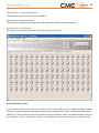
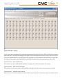
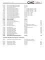
1
User manual
NeoSynth
Audio expansion card for CME
VX and UF keyboard range
Version 1.1
2
Special messages section
This product utilizes batteries or an external power supply (adapter). Do NOT connect this product to any
power supply or adapter other than one described in the manual, on the product, or specifically recommended by CME.
Warning
Do not place this product in a position where anyone could walk on, trip over, or roll anything overpower
or connecting cords of any kind. The use of an extension cord is not recommended! If you must use an extension cord, make sure that the cord has the ability to handle maximum current needed by this product.
Please consult a local electrician when possible.
This product should be used only with the components supplied or recommended by CME. When used
with any components, please observe all safety markings and instructions that accompany the accessory
product.
Specifications subject to change
The information contained in this manual is believed to be correct at the time of printing. However, CME
reserves the right to change or modify any of the specifications without notice or obligation to update existing units.
This product, either alone or in combination with an amplifier and headphones or speaker(s), may be capable of producing sound levels that could cause permanent hearing loss. Do NOT operate for long periods of time at a high volume level or at a level that is uncomfortable. If you experience any hearing loss
or ringing in the ears, you should consult an audiologist.
Important
The louder the sound, the shorter the time period before damage occurs. Some CME products may have
stands and/or accessory mounting fixtures that are either supplied with the product or as optional accessories. Some of these items are designed to be dealer assembled or installed. Please make sure that
stands are stable and any optional fixtures (where applicable) are well secured BEFORE using. Stands supplied by CME are designed for the respect products only. No other uses are recommended.
Notice
Service charges incurred due to a lack of knowledge relating to how a function or effect works (when the
unit is operating as designed) are not covered by the manufacturer’s warranty, and are therefore the owners responsibility. Please study this manual carefully and consult your dealer before requesting service.
environmental issues
CME strives to produce products that are both user safe and environmentally friendly. We sincerely believe
that our products and the production methods used to produce them, meet these goals. In keeping with
both the letter and the spirit of the law, we want you to be aware of the following:
3
Battery notice
This product MAY contain a small non-rechargeable battery which (if applicable) is soldered in place. The
average life span of this type of battery is approximately five years. When replacement becomes necessary, contact a qualified service representative to perform the replacement.
This product may also use“household”type batteries. Some of these may be rechargeable. Make sure that
the battery being charged is a rechargeable type and that the charger is intended for the battery being
charged.
When installing batteries, do not mix batteries with new, or with batteries of different type. Batteries MUST
be installed correctly. Mismatches of incorrect installation may result in overheating and battery case rupture.
Warning
Do not attempt to disassemble, or incinerate any battery. Keep all batteries away from children. Dispose
of used batteries promptly and as regulated by the laws in your area. Note: Check with any retailer of
household type batteries in your area for battery disposal information.
Disposal notice
Should this product become damaged beyond repair, or for some reason its useful life is considered to be at an
end, please observe all local, state, and federal regulations that relate to the disposal of products that contain
lead, batteries, plastics, etc. If your dealer is unable to assist you, please contact CME directly.
4
FCC information (U.S.A.)
Important notice: do not modify this unit!
This product, when installed as indicated in the instructions contained in this manual, meets FCC requirements. Modifications not expressly approved by CME may void your authority, granted by the FCC,
to use the product.
Important
When connecting this product to accessories and/or another product use only high quality shielded cables. Cable(s) supplied with this product MUST be used. Follow all installation instructions. Failure to follow instructions could void your FCC authorization to use this product in the USA.
Note
This product has been tested and found to comply with the limits for a Class B Digital device, pursuant to
Part 15 of the FCC Rules. These limits are designed to provide reasonable protection against harmful interference in a residential environment. This equipment generates, uses and can radiate radio frequency
energy and, if not installed and used according to the instructions found in the users manual, may cause
interference harmful to the operation of other electronic devices.
Compliance with FCC regulations does not guarantee that interference will not occur in all installations.
If this product is found to be the source of interference, which can be determined by turning the unit
“OFF” and “ON”, please try to eliminate the problems by using one of the following measures:
- Relocate either this product or the device that is being affected by the interference.
- Utilize power outlets that are on different branch (circuit breaker or fuse) circuits or install AC line filter(s).
- In the case of radio or TV interference, relocate/reorient the antenna. If the antenna lead-in is 300 ohm
ribbon lead, change the lead-in to co-axial type cable. If these corrective measures do not produce satisfactory results, please contact the local retailer authorized to distribute this type of product. If you cannot
locate the appropriate retailer, please contact CME.
The above statements apply ONLY to those products distributed in the USA.
5
Table of contents
Introduction
6
Terminology
What’s in the box?
6
6
Installing the Neosynth expansion board into your CME keyboard
8
NeoSynth inputs and outputs
9
Connections
9
General
12
Leds behaviour
Sound bank upgrade
USB MIDI driver
12
12
12
The patch editor software
13
Preference Screen
Routing screen
Inputs FX screen
Synth FX screen
Synth channels A screen
Synth channels B screen
Synth channels C screen
Sound bank screen
The menu items of the patch editor
14
16
19
23
28
29
31
33
35
The NeoSynth features
39
MIDI implementation of the NeoSynth
40
6
Introduction
First of all, congratulations with the purchase of the Neosynth! With this expansion board from WaveIdea
you will add great sonic possibilities to your CME VX or UF keyboard.
In short the expansion board gives you the possibility to play high quality sounds in various music styles
provided in sound banks that can be loaded from an optional SD card that fits into the expansion board.
You can also change settings for sounds, MIDI channels etc. with the provided software patch editor.
With an external MIDI sequencer you can use the NeoSynth in multitimbral mode up to 16 MIDI channels.
Wave Idea will develop new sound banks in the future to fulfill all your sonic needs!
Depending on the sound bank, variations may also exist, so more than 128 sounds can be available.
Terminology
As a reference here is a short list of specific NeoSynth terms used in this manual.
Soundbank. This is what you have loaded into the NeoSynth. It’s a set of (multi)samples, created by professional sound designers and determines how each of the instruments will sound.
Instrument: one sound from a sound bank with specific (multi)samples creating the sound plus specific settings for the instrument (for instance FX, filter, etc.).
Preset or patch: a set of parameters that describes all settings for a sound bank. It contains the 16 possible sounds for each MIDI channel, the effect settings, the audio routing settings etc. You create presets with
the additional patch editor software and can save them on your computer.
Synthesizer channel: A term used to describe one of the 16 possible instruments that can sound at the
same time in a so-called multitimbral setting. Because the NeoSynth listens to MIDI you can play 16 instruments at the same time over a maximum of 16 different MIDI channels.
One of those instruments with its specific settings and MIDI channel is called a synthesizer channel.
What’s in the box?
Before you go on installing the expansion board please check if your box contains all the shipped items.
– NeoSynth Board;
– Rear plate for UF keyboard;
7
– Rear plate for VX keyboard;
– CD-ROM;
– Manual;
– SD-card with GM sound Bank;
– USB cable.
8
Installing the Neosynth expansion board into your CME VX or UF keyboard
First of all, be sure to unplug the power plug and USB cable from your keyboard to avoid electrical shortcuts during installation.
Also be sure to ground yourself to avoid static electricity which could damage your NeoSynth expansion
board. Do not touch electronic parts of the expansion board either since this can damage the expansion
card as well.
Step 1:
Unscrew the metal plate on your VX or UF keyboard on the back. The plate is holded by 4 screws on the
VX keyboard and 5 screws on the UF keyboard ( next three pictures shows the VX version).
Step 2:
Locate the power/communication connector that should be connected to the Neosynth expansion board
(1 connector on the VX keyboard, 2 smaller connectors on the UF keyboard).
Connectors feature a mounting direction, the right direction must be respected, no force must be applied
while inserting the connector(s).
9
Step 3:
Gently insert the Neosynth expansion board into the VX or UF keyboard and place the 4 respectively 5
screws to tighten the Neosynth expansion board.
Step 4:
The quickest way to be able to make sure your Neosynth is installed correctly is to plug in a headphone
in the NeoSynth’s headphones output and play the demo on your VX or UF keyboard (see the respective
VX or UF keyboard manual how to do that. On the VX press the expansion link button).
Another way is to attach one or two audio cables from your Neosynth to your DAW, computer or amplifier to be able to hear the synth.
Attach a USB cable from your Neosynth to your computer to be able to edit instruments etc. with the provided patch editor software.
Step 5:
Power on the VX or UF keyboard. While doing that watch the back of the keyboard and see if the two leds
on the Neosynth expansion board lit up (one yellow and one red one should go on for a few seconds and
then go off again). When a USB cable is connected to your computer the red led will burn.
For more information about selecting the NeoSynth and choosing the various sounds please read the
manual provided with your VX/UF keyboard.
By now it should be possible to play and hear the sounds of the Neosynth.
NeoSynth inputs and outputs
Connections
The Neosynth expansion board has several connection possibilities to increase the use in all kinds of settings (Grey NeoSynth: UF version, Red NeoSynth: VX version).
From left to right:
10
Headphones output (stereo):
A stereo output, mirrored from the main outputs with it’s own dedicated mixer in the patch editor.
Note : By default, this output is connected to the synthesizer part of the NeoSynth.
Master output (L+R):
These outputs can be connected to your DAW, audio card, amplifier etc.
Note : By default, this output is connected to the synthesizer part of the NeoSynth
Auxilliary (Aux) output (L+R):
These outputs can be connected to your DAW, audio card, amplifier etc. and can be used as an extra pair
of outputs, but also as a send/return together with the inputs to be able to use an external effect box with
your Neosynth.
Audio in (L+R):
Here you connect any audio signal for various applications:
1. Make use of the FX section of the Neosynth. Since the synthesizer has a nice Reverb and Delay effect,
you can route any audio through those effects
2. Same as 1, but now mixed with your synthesizer track! With the use of the patch editor you can make
extensive mixes of both the input and synthesizer audio signal.
3. You can even use the inputs for karaoke! Connect a microphone through a microphone amplifier, use
a GM soundset, play a General Midi songfile and sing along with it.
Digital output (stereo):
This is a mirror of the Analog Auxiliary Outputs and can be connected to a digital input on your audiocard,
DAW, etc. it provides a 16 bit/48 kHz signal.
Note : By default, this output is connected to the inputs part, passing through the input FX engine of the
NeoSynth.
Note 2: The equipment connected to the NeoSynth S/PDIF output must be configured to recover the
S/PDIF clock from the NeoSynth S/PDIF output (slave equipment)
Red and orange leds
These two leds will help you to see the in which mode the NeoSynth is acting. You’ll find more info in this
manual about the various possible combinations for on/off or blinking leds.
USB connector
For use with a hardware expander to be able to edit instrument, FX and routing parameters using the provided patch editor software.
The Neosynth is class compliant with the USB MIDI specification, thus it does not need any driver to work
with Xp-Sp2, Vista, Mac and Linux.
A special driver is available for Win Xp, it is not mandatory to install it, it is just used to replace the generic
device name “USB audio device” by “WaveIdea Neosynth”
11
SD-card slot
Here you can put in a SD card for loading various sound banks.
As soon as the sound bank has been updated, the SD card can be removed from the slot.
There are two ways for loading a sound bank from a SD card:
Software-less
The update can be done by inserting the card, reboot the VX or UF keyboard while holding the button besides the SD card slot. The Neosynth will read the sound bank from the SD card that way.
Using the patch editor
To update from the SD-card using the patch editor: put the card into your VX or UF keyboard.
Connect the Neosynth through USB to your computer, open the patch editor software and connect to
the NeoSynth in the Preferences tab. Go to the sound bank panel (last tab) and click the button. A window
will appear explaining how to upgrade. See also the next chapter about the patch editor
12
General
Leds behaviour
The behaviour of the leds on the Neosynth says something about the status of the NeoSynth in various
conditions:
Status 1 led Status 2 led
Yellow
Red
Normal mode
Neosynth is booting
On
On
Neosynth idle
Off
Off
Neosynth idle – USB attached
Off
On
Neosynth playing – USB attached/not attached
Lighting
On/Off
Sound bank or firmware upgrade mode
Previous sound bank erase
Sound bank upgrading
Firmware upgrading
Firmware upgrade finished - Success
Sound bank upgrade finished - Success
Sound bank upgrade finished – Invalid SD card
Sound bank upgrade finished - Error
Ping pong fast
Ping pong slow
Ping pong fast
On
On
On
On
Off
Off
On
Off
Sound bank upgrade
This is done in 2 steps :
1. Erasing of previous sound bank : Leds will ping pong fast : requires about 7 minutes.
If using patch editor software, a progression bar is available for this first step;
2. Upgrade of new sound bank : Leds will ping pong slow : requires about 13 minutes.
If using patch editor software, a progression bar is available for this second step
See the next chapter about the patch editor software for details on this.
USB MIDI driver
The Wave Idea NeoSynth USB MIDI driver for Windows XP can be installed if you want to change the generic
Windows XP USB MIDI driver name. But it is not demanded. For a description of the installation progress visit
WaveIdea’s website (http://www.waveidea.com) to download and read the PDF manual for that.
13
The patch editor software
The fun of the Neosynth doesn’t stop here! When you have attached a USB cable to the Neosynth from your
computer and installed the patch editor software (both Windows and Macintosh versions are available),
you can change the sounds, store them, and make all kinds of settings for multitimbral use of the synthesizer in conjuction with a MIDI sequencer.
In this manual we will take an extensive look at the parameters that can be changed using the patch editor.
To do so, you need to connect your computer with the Neosynth through a USB-connection. There is no
need for a driver, it is plug and play. Even in Windows XP, although you could use the provided driver to
change the “universal USB device”-name into “Neosynth” as device name.
Installing the editor (Windows):
Unzip the editor file on the CD onto your harddrive. Then run the installer.
Installing the editor (Macintosh):
Unzip the editor file from the CD onto your harddrive. That will create a DMG file on the desktop from
which you can copy the program into the programs folder on your Mac.
If you have made the USB-connection and turned on the VX or UF keyboard you can start up the patch
editor. It will start up with this first screen, the “Preferences” screen.
The upper part of every screen in the patch editor will have the same parameters:
In here you can select various MIDI settings etc. We will go through every parameter of this screen first (see
screen shot next page):
First you can select one of the 16 preset slots. A preset will contain all settings for the 16 channels. You can
see a preset as a container for a multitimbral setup with a maximum of 16 (MIDI)channels. It contains the
audio routing settings for the synth and the external inputs, the effect settings, the MIDIchannel settings,
the so-called synth channel settings, containing parameters like filter cutoff, resonance, attack, decay, release etc. You can create as many as 16 presets.
Furthermore there are three buttons “Send”, “Receive” and “Reset”. With these three buttons you can send
a preset to the NeoSynth, receive a preset from the NeoSynth and reset the NeoSynth to the factory preset. To the right of these knobs you see the preset number that is selected for sending or receiving, a progressbar which shows the progress of sending or receiving a preset plus two MIDI indicators, telling you
if there is action going on on the MIDI in and/or MIDI out port. The user can change the name of the preset in the textfield. By default the names are Preset 1, Preset 2 etc.
14
Preference Screen
MIDI devices – MIDI In
In this pop-up screen you can choose the available MIDI device to send preset data to, in our case the
NeoSynth. Midi in & out selections are saved so thet are retrieved next time you start the software.
MIDI devices – MIDI Out
In this pop-up screen you can choose the available MIDI device to receive preset data from, in our case the
NeoSynth. Midi in & out selections are saved so thet are retrieved next time you start the software.
MIDI devices - Connect to NeoSynth
Clicking this button will make a connection with the NeoSynth to show you the firmware version, the
hardware version and the serial number (under the knob). As soon as you see that info appear you know
that the connection has been made with the Neosynth.
15
Misc. – Auto send
When selected, the software editor will send every parameter change made in the editor immediately.
When unselected you will have to use the “Send” button in the upper screen to send the whole preset to
Neosynth. Also you can right click on a knob or any other control to send it indiviually. (On OSX controlclick).
Misc. – Link Left & Right parameters
With this one selected all parameters that have a left and right version are linked, meaning if you change
one of them, the other one will change too with the same value. When unselected you can make complete
individual settings for the left and right version of a parameter.
Misc. – MIDI thru
When the box is checked, all incoming MIDI data in the software will be forwarded to the MIDI out, so this
has to be used with care since it can result in a MIDI loop (a confirmation box appears in the software
mentioning this possible MIDI loop).
The MIDI thru can be used with a MIDI file player connected to the soft input. This way you can change
the sounds by turning knobs in the software while the MIDI song is playing.
Misc. – All sounds off
Pressing this button will send a all notes off message to all 16 MIDI channels. This comes in handy when
somehow the MIDI messages are messed up and you hear notes that won’t stop anymore.
16
Routing screen
There are two stereo audio paths that can be mixed and panned in all kinds of ways. One stereo path
(from here called external audio) is the line in left and right analog inputs going through a effects section
which is then routed to the S/PDIF output (stereo) and mirrored on the left and right auxilary outputs. On
top of that you can mix this external audio signal into the synth audio path.
The second audio path is the stereo synthesizer audio path (from here called synth audio) coming out of
the synthesizer engine and is going through the effects section, then going through a mixer where you
can make settings for the 16 channels and then going out of the Master left and right outputs and Headphones output (stereo). This audio path can also be mixed into the external audio path.
You can even connect externally with two short audio cables the master L+R master outputs to the Line
in L+R inputs to make use of an extra external FX box!
First, let’s go through all the controls possible in this screen. We are going from left to right and from up
17
to down.
LINE IN L+R level control
This knob controls how much signal that comes in from the line inputs will be fed into the stereo signal
path.
Enable inputs
This checkbox enables/disables the inputs.
The external audio path is split into left and right paths each with its own panning and level control.
This makes it possible to have two completely independend mono signals going through the external
audio effects section where they can have different settings.
Summed external audio left channel pan control
This knob controls the panning of the audio signal from the left external audio path. So you can feed
something or a lot into the right channel as well.
It is fed into the external audio path after the level control of the right channel.
Summed external audio left channel level control
This knob controls the level of the audio signal from the left external audio path going into the effects section.
Summed external audio right channel pan control
This knob controls the panning of the audio signal from the right external audio path. So you can feed
something or a lot into the left channel as well.
It is fed into the external audio path after the level control of the left channel.
Summed external audio right channel level control
This knob controls the level of the audio signal from the right external audio path going into the effects
section.
After these controls the external audio goes into the dedicated effects section. See further on for details
the Inputs FX section. When the audio comes out of the effects section there are even more controls!
External audio output level control
First there is a level control which controls the amount of signal going to the digital S/PDIF output (stereo)
and the auxiliary outputs (left and right).
External audio mixing level control
This is a level control which controls the amount of the external audio signal that comes out of the effects section which will be fed into the synth audio path.
Now we are going to take a look at the synth audio path.
18
The left and right output of the synthesizer channels (16 at maximum) are fed into the dedicated synthesizer effects section. Later on in this manual the effects are explained in the Synth FX section. After the
synth FX section you see two controls.
Synth audio post effects panning control
This control determines how much of the stereo signal from the synthesizer channels goes left and right.
You can see it as a main panning control for all synthesizer channels.
Synth audio post effects level control
This control gives control over the combined level of all 16 synthesizer channels coming out of the synthesizer effects section. You an see it as a main output level control for the synthesizer audio paths.
Please be aware that you can control panning and level for each individual synthesizer channel in the
Synth Channels B screen!
Synth audio path switches
Here you see a block with two rows of 16 checkboxes. These boxes control if the audio coming out of the
synth effects section will go to the digital S/PDIF and auxiliary outputs or go to the Master and headphones outputs. The 16 boxes corresponds to the 16 MIDI channels of the synth. This way you can for instance direct a drum section of GM channel 10 to the aux outputs while the rest of the channels go to the
main outputs.
The last control in this screen is the level control for the headphones output.
It’s your own brain that can come up with good use of these possibilities. It is for instance possible to
route one or more of the 16 synth channels to the auxiliary outputs so you can put this signal through a
dedicated outboard effect. For instance having a dedicated outboard delay on one or more tracks. Or a
compressor on the drumtrack (when you use a GM sound bank).
You can even use it as a send/return by routing something to the auxiliary outputs, put it through an effect and send that signal back into the NeoSynth using the line in inputs, make use of it’s dedicated effects
block and bleed it into the master out mix!
19
Inputs FX screen
In this screen you can make all the effects settings of the external inputs dedicated effects blocks.
There is a stereo reverb, stereo delay and a stereo equalizer available, to sculpt your sounds in detail.
Let us take look at all the controls:
First there are three checkboxes to enable/disable each effect. If you don’t need one or more of the effects
it is wise to turn them off, since that will increase polyphony of the synth module.
Enable Reverb
This checkbox enables/disables the Reverb effect.
Enable Delay
This checkbox enables/disables the Delay effect.
20
Enable Eq
This checkbox enables/disables the Equalizer effect.
REVERB
The reverb effects gives space to a sound and is mostly used to make a sound more natural, by adding simulated reflection signals like they exist in the real world.
We all know how our voice sounds inside a cathedral or the bathroom. That effect is called reverb. The
sound of our voice reflects against walls, ceilings, floors, objects and gets back to our ears with a very
small delay in time. All those thousands(!) of reflections together make the reverb effect. The bigger the
hall or room the longer the reverb sounds.
Reverb – level control
This slider controls the level of the Reverb signal going out of the Reverb FX.
Reverb – Time control
This slider controls the decay of the reverb effect. Higher settings give longer reverb tails.
Reverb – send controls (left and right)
These two sliders control the level of the dry signal going into the Reverb FX. they have a close relations
with the Reverb level control on the left. Remember: under the Preferences tab you can set to link the
two sliders by enabling the checkbox Link left & right parameters.
DELAY
Delay (or echo) is an effect similar to reverb, but the time the sounds needs to get back to our ears from
walls, ceilings, floors, mountains(!) etc. is so long that we “hear” the silence in between. It is the effect of
screaming in the mountains: after some time you hear your voice coming back from the mountain walls
it reflected on.
In the early days of electronics this effect was created by recording the audio on a tape and playing it back
from that same tape with a gap from about 200 ms to sometimes several seconds. Later on this effect
could be simulated electronically and digitally. You can do nice rhythmical things with it!
Delay – level control
This slider determines the level of the delay signal going out of the Delay FX.
Delay – Time control
This slider dertermines the“gaps” between the dry signal and the delayed signal. It various from 0 to about
1000 milliseconds. With very small settings you can thicken up your sounds. With higher settings you can
create rhythmical sounds.
Delay – Send controls (left and right)
These two sliders (L+R) determine how much of the dry signal will be fed into the Delay FX.
21
Delay – Feedback control
This slider determines how much of the Delay signal is fed back into the Delay FX. With higher settings it
takes a longer time for the delay signal to fade out.
Delay – Filter control
This slider determines how much filtering will take place on the delay signal. With higher settings you can
simulate old tape machines that loose high frequencies on the delay signal by their nature.
The filter is a 6 dB lowpass filter inserted in the feedback loop.
Delay – Delay into Reverb control
This slider determines how much of the Delay signal will be fed back into the Reverb FX. Set to 0 only the
dry signal will go through the Reverb FX. Higher settings will have a reverb on the delay signal as well.
Delay – Delay line 1 level controls (left and right)
This slider determines the level of the main delay line whose delay time has been set with the Delay Time
slider. So maximum delay times (1000 ms) will be made with this delay line.
Delay – Delay line 2 level controls (left and right)
This slider sets the level of a second delay line, whose time is derived from the Delay time setting. The
delay time for delay line 2 is 1/3 of the time made with the Delay time setting. For instance, if the delay
time of delay line 1 is about 750 ms, this delay line will produce a delay signal after 250 ms.
Delay – Delay line 3 level controls (left and right)
This slider sets the level of a second delay line, whose time is derived from the Delay time setting. The
delay time for delay line 2 is 1/3 of the time made with the Delay time setting. For instance, if the delay
time of delay line 1 is about 750 ms, this delay line will produce a delay signal after 500 ms.
EQUALIZER
This effect is actually a number of filters that control specific parts of the soundspectrum. With an equalizer you can enhance or push back certain frequency ranges like the bass frequencies, middle frequencies
or high frequencies of a sound. It’s a perfect effect to make a sound stand out in a mix of various sounds.
Or to cut off some irritating frequencies in a sound.
It’s a 4 band equalizer with gain and frequency controls and a bandwith control for the two mid bands.
Note that you have a complete independent equalizer effect for both the left and right audio channel.
Equalizer – low gain control
This knob controls the level of the gain for the low frequency. 0 = -12 dB, 127 = +12 dB.
Equalizer – low frequency control (up to 1.25 Khz)
This knob controls the low frequency that can be level controlled by the low gain control.
22
Equalizer – mid 1 gain control
This knob controls the level of the gain for the medium 1 frequency. 0 = -12 dB, 127 = +12 dB.
Equalizer – mid 1 frequency control (up to 1.4 Khz)
This knob controls the medium 1 frequency that can be level controlled by the medium 1 gain control.
Equalizer – mid1 bw control
This knob controls the slope or bandwidth of the medium 1 frequency that can be set by the mid 1 frequency control. Low values give a small bandwith (1/6 octave), high values give a broad bandwith (3 octaves).
Equalizer – mid 2 gain control
This knob controls the level of the gain for the medium 2 frequency. 0 = -12 dB, 127 = +12 dB.
Equalizer – mid 2 frequency control (up to 1.4 Khz)
This knob controls the medium 2 frequency that can be level controlled by the medium 2 gain control.
Equalizer – mid2 bw control
This knob controls the slope or bandwidth of the medium 2 frequency that can be set by the mid 2 frequency control. Low values give a small bandwith (1/6 octave), high values give a broad bandwith (3 octaves).
Equalizer – high gain control (up to 5.2 Khz)
This knob controls the level of the gain for the high frequency. 0 = -12 dB, 127 = +12 dB.
Equalizer – high frequency control
This knob controls the high frequency that can be level controlled by the high gain control.
23
Synth FX screen
In this screen you can make all the effects settings for the synthesizer channels. The effects are globally
used for all 16 synthesizer channels. The provided effect blocks are different from the ones in the external audio path.
There is a stereo reverb, stereo chorus, a stereo equalizer and a so called spatializer available to sculpt
your synthesizer sounds in detail. In this synth audio path effects section the controls are always combined controls for left and right
Let us take look at all the controls in this section.
First there are four checkboxes to enable/disable each effect. If you don’t need one or more of the effects
it is wise to turn them off, since that will increase polyphony of the synth module.
24
Enable Reverb
This checkbox enables/disables the Reverb effect.
Enable Chorus
This checkbox enables/disables the Delay effect.
Enable Eq
This checkbox enables/disables the Equalizer effect.
Enable Spatializer
This checkbox enables/disables the Spatializer effect.
REVERB
For a overall function of the reverb effect see the description at the Input FX section above.
The reverb controls here differs from the reverb controls in the external audio path effects section. It has
more extended controls.
Reverb – level control
This slider controls the amount of dry signal going into the reverb effect.
Reverb – main level control
This knob controls the amount of reverb signal going to the main outputs.
Reverb – aux level control
This knob controls the amount of reverb signal going to the aux outputs.
Reverb – type control
This knob sets the type of the reverb. There are 8 settings:
0. Room 1
1. Room 2
2. Room 3
3. Hall 1
4. Hall 2
5. Plate
6. Delay
7. Pan Delay
Reverb – pre-low pass filter control
This knob controls the cutoff frequency of the signal that is going into the reverb effect.
25
Reverb – time control
This knob controls the time of the reverb tail. Low settings have a short reverb tail, high settings make a
long reverb tail.
Reverb – delay control
This knob controls the delay time for the reverb types 6 and 7.
CHORUS
In simple terms the chorus effect thickens a sound by adding a slightly changed copy of the orginal to the
original. The change is in the pitch of the copy. Because it is very little difference, our ears do not perceive
the sound as out of tune. Parameters like delay and pitch modulation will add to this effect. Extreme settings can create real different sounds though.
Chorus – main level control
This knob controls the amount of chorus signal going to the main outputs.
Chorus – aux level control
This knob controls the amount of chorus signal going to the aux outputs.
Chorus – chorus into reverb level control
This knob controls the amount of chorus signal going back into the reverb effect.
Chorus – type control
This knob sets the type of chorus. There are 8 different types.
0. Chorus 1
1. Chorus 2
2. Chorus 3
3. Chorus 4
4. Feedback
5. Flanger
6. Short delay
7. Feedback delay
Chorus – pre-low pass filter control
This knob controls the cutoff frequency of the signal that is going into the chorus effect.
Chorus – delay control
This knob controls the delay time
Chorus – feedback control
This knob sets the amount of chorus signal that is fed back into the chorus effect.
26
Chorus – rate control
This knob controls the rate of the chorus effect.
Chorus – depth control
This knob controls the depth of the chorus effect.
EQUALIZER
This effect is actually a number of filters that control specific parts of the soundspectrum. With an equalizer you can enhance or push back certain frequency ranges like the bass frequencies, middle frequencies
or high frequencies of a sound. It’s a perfect effect to make a sound stand out in a mix of various sounds.
Or to cut off some irritating frequencies in a sound.
It’s a 4 band equalizer with gain and frequency controls and a bandwith control for the two mid bands.
Note that you have a complete independent equalizer effect for both the left and right audio channel.
Equalizer – low gain control
This knob controls the level of the gain for the low frequency. 0 = -12 dB, 127 = +12 dB.
Equalizer – low frequency control (up to 1.25 Khz)
This knob controls the low frequency that can be level controlled by the low gain control.
Equalizer – mid 1 gain control
This knob controls the level of the gain for the medium 1 frequency. 0 = -12 dB, 127 = +12 dB.
Equalizer – mid 1 frequency control (up to 1.4 Khz)
This knob controls the medium 1 frequency that can be level controlled by the medium 1 gain control.
Equalizer – mid1 bw control
This knob controls the slope or bandwidth of the medium 1 frequency that can be set by the mid 1 frequency control. Low values give a small bandwith (1/6 octave), high values give a broad bandwith (3 octaves).
Equalizer – mid 2 gain control (up to 1.4 Khz)
This knob controls the level of the gain for the medium 2 frequency. 0 = -12 dB, 127 = +12 dB.
Equalizer – mid 2 frequency control
This knob controls the medium 2 frequency that can be level controlled by the medium 2 gain control.
Equalizer – mid2 bw control
This knob controls the slope or bandwidth of the medium 2 frequency that can be set by the mid 2 frequency control. Low values give a small bandwith (1/6 octave), high values give a broad bandwith (3 octaves).
27
Equalizer – high gain control (up to 5.2 Khz)
This knob controls the level of the gain for the high frequency. 0 = -12 dB, 127 = +12 dB.
Equalizer – high frequency control
This knob controls the high frequency that can be level controlled by the high gain control.
SPATIALIZER
This effect can enhance the “stereo feeling” of a sound or sounds. You can also use it with a 4 speaker setting when you use both the main outputs and the aux outputs together.
Spatializer – level control
This slider controls the amount of signal going into the spatializer effect.
Spatializer – Delay control
This control sets the amount of delay signal that creates the spatial effect. Higher settings give a more
pronounced spatial effect.
Spatializer – stereo/mono checkboxes
These checkboxes determine if a stereo or mono signal goes into the spatializer effect.
Spatializer – main+aux/main checkbox
These checkboxes determine if the spatializer signal goes to the main outputs plus the aux outputs or
only to the main outputs.
28
Synth channels A screen
In this first of three synth channels screens you can alter various parameters that will change a synthesizer
sound. You can make these changes for each of the 16 individual synthesizer channels.
Synth channel A – portamento checkbox
With this checkbox you can turn the portamento on or off. Portamento is also called glide. It is an effect
where the pitch of the sound ‘glides’ from one key to the other.
Synth channel A – wheel level control
This knob sets the modulation depth of the modulation wheel on your controller keyboard
Synth channel A – portamento control
This knob sets the portamento or glide rate, i.e. how fast the pitch glides from one to the other note.
29
Synth channel A – express level control
This knob sets the level of the expression pedal.
Synth channel A – panning control
This knob sets the panning of each individual synthesizer channel in the stereo field.
Synth channel A – level control
This slider controls the level of each individual synthesizer channel.
Synth channels B screen
In this second screen you can alter level settings for the various effects plus an additional effect: vibrato.
Vibrato is an effect where you change the pitch of the original sound using a so called low frequency oscillator. It is used to simulate various real world instruments like flutes, where you make this effect with your
lips and fingers, or on a string from a violin, by stretching the snare with your finger in a rhythmic way.
30
Synth channel B – reverb level control
This knob sets the amount of signal that is going into the reverb effect for each of the 16 individual synth
channels.
Synth channel B – chorus level control
This knob sets the amount of signal that is going into the chorus effect for each of the 16 individual synth
channels.
Synth channel B – vibrato rate control
This knob sets the rate of the vibrato for each of the 16 individual synth channels.
Synth channel B – vibrato depth control
This knob controls the depth of the vibrato effect for each of the 16 individual synth channels.
Synth channel B – vibrato delay control
This knob sets the time before the vibrato effect is coming up after a key is pressed. Again you can set this
for each of the 16 individual synth channels.
Synth channel B – pitch control
This knob sets the global pitch for each of the 16 individual synth channels.
31
Synth channels C screen
In this screen you can change the cutoff and resonance of the built-in low pass filter. Such a filter can have
great effect on a sound by removing certain parts of the soundspectrum of that sound, in this case by filtering out high frequencies. The effect gets even greater by an extra parameter, the resonance control. With
this control you enhance the frequencies around the the point from where frequencies are cut off.
Synth channel C – filter cutoff control
This control sets the cutoff value of the filter. The higher the value the brighter the sound.
Synth channel C – filter resonance control
This control sets the resonance level of the filter, the higher the value the more resonance you hear.
Synth channel C – amplifier attack control
The control sets the time it take for the level of the sound to reach it’s maximum value. At zero the sound
32
will sound immediately at it’s maximum value, higher values makes the sound come up in level in a certain time.
Synth channel C – amplifier decay control
Decay control sets the time a sound will go on while a key is pressed. Low values makes that a short time,
the highest value will make the sound go on until you release the key.
Synth channel C – amplifier release control
This control sets the time a sound will go on after you have released the key. A low value will drop the
soundlevel immediately while a high value will make the sound go on for some time after you released
the key.
With the Attack, Decay and Release controls you “shape” the volume of the sound in time. These controls
are very important. A pad or string sound needs slow attack and a longer release, while a piano or organ
sound needs a fast attack and a slower release for instance.
-->
S
y
x--> A
D
R
Here you see a typical ADSR curve. On the x-axe time is represented, on the y-axe it’s the amplitude of the
volume of the sound.
The standard envelope form is ADSR, which start with Attack time (A) from minimum level to maximum,
falls back to Sustain level (S) with Decay (D) time. After key release with Release time (R) the signal will go
back to 0 (if Sustain level was 0 nothing happens after Decay time has passed).
On the NeoSynth there is no sustain control and the sound falls in the release time back to zero after the
decay time has passed.
33
Sound bank screen
In this screen you can make various settings for bank and program selection on the 16 MIDI channels. You
can also upgrade a sound bank from this field. Beware that we are talking about two different types of
banks here! The first control (bank select) is a controller to select a bank which contains a maximum of 128
programs (or instruments). The upgrade sound bank button refers to a sound bank which contains all the
(multi)samples which provides the raw material for the synthesizer to process and create sound with.
So a sound bank is a file and container for the (multi)samples which can be loaded into the NeoSynth.
A bank is a container for 128 programs. A sound bank can contain 4 banks of 128 sounds for instance.
Sound bank – bank select control
With this control you can select various banks on the NeoSynth per MIDI channel. Each bank can contain
a maximum of 128 progams.
Sound bank – program channel
With this control you can select the program for every midi channel within the chosen bank. There are a
34
maximum of 128 programs in a bank.
Sound bank – include to presets
This checkbox determines if the made settings for bank select and program channel will be included in
the active preset when saved.
Sound bank – sound bank name
Here you can see the name of the sound bank that is going to be uploaded to the NeoSynth.
Sound bank – sound bank size (MB)
Here you can see the size of the sound bank that is going to be uploaded to the NeoSynth.,
Sound bank – upgrade sound bank
This knob starts the upload of the sound bank to the NeoSynth.
35
The menu items of the patch editor
In the main menu bar there are some global parameters like saving, opening, connecting and other features. We will shortly describe them here, since most of them are pretty obvious.
FILE
File – New patch
This will create a new patch. A patch is a complete setting of 16 presets which can be made with the
NeoSynth patch editor. You can save these patches on your computer.
File – Open patch
With this command you can open a saved patch.
File – Save patch
With this command you can save a newly made patch on your computer.
36
File – Save patch as
With this command you can save an existing patch with a different name, to be able to keep the original
patch.
File – Reset patch to default
With this command you can reset all 16 presets to default values.
File – Quit
This command quits the patch editor software.
PRESET
Preset – Send
A preset is a complete setting for the NeoSynth, including the synthchannel settings etc.
With this command you can send a preset to the NeoSynth (remember, in the preferences tab you can
choose to automatically send every change you make in the software, including sending presets!)
37
Preset – Receive
With this command you can request the preset settings that are in the NeoSynth.
Preset – Copy
With this command you can make copy of the preset settings and paste it into another preset with the preset paste command.
Preset – Paste
With this command you can paste a copied preset into another preset.
Preset – Reset to default
This command resets the active preset in the software to default values.
PREFERENCES
38
MIDI devices – MIDI In
In this pop-up screen you can choose the available MIDI device to send preset data to, in our case the
NeoSynth. Midi in & out selections are saved so thet are retrieved next time you start the software.
MIDI devices – MIDI Out
In this pop-up screen you can choose the available MIDI device to receive preset data from, in our case the
NeoSynth.Midi in & out selections are saved so thet are retrieved next time you start the software.
MIDI devices - Connect to NeoSynth
Activating this line will make a connection with the NeoSynth to show you the firmware version, the hardware version and the serial number (under the knob). As soon as you see that info appear you know that
the connection has been made with the Neosynth.
Misc. – Auto send
When selected, the software editor will send every parameter change made in the editor immediately.
When unselected you will have to use the “Send” button in the upper screen to send the whole preset to
Neosynth. Also you can right click on a knob or any other control to send it indiviually. (On OSX controlclick).
Misc. – MIDI thru
When the box is checked, all incoming midi data in the software will be forwarded to the MIDI out, so this
has to be used with care since it can result in a midi loop (a confirmation box appears in the software
mentioning this possible midi loop).
The midi thru can be used with a midi file player connected to the soft input. This way you can change the
sounds by turning knobs in the software while the midi song is playing.
Misc. – Link Left & Right parameters
With this one selected all parameters that have a left and right version are linked, meaning if you change
one of them, the other one will change too with the same value. When unselected you can make complete
individual settings for the left and right version of a parameter.
HELP
choosing this menu item you will get into a help file that basicly contains the same info as this manual
as far as it concerns the use of the patch editor software.
39
The NeoSynth features
The Neosynth from WaveIdea is an expansion card suitable for the CME VX and UF keyboard range.
– It is a MIDI/USB expander;
– It has up to 124 voice of polyphony;
– There are built-in effect engines for both the input audio path as well as the synthesizer audio path;
– Effects are Reverb, Delay, Equalizer, Chorus, Spatializer;
– Each sound bank can contain up to 64 MB of sounds;
– Soundbanks are updatable from a SD card. The software editor (both Mac and Windows are available)
shows the progress of this;
– WaveIdea has various sound banks available for all kinds of musical styles;
– USB is MIDI class compliant (no driver needed);
– The audio paths are 24 bits / 48 KHz;
– Main stereo audio outputs (24 bits DA convertors, DAC output voltage is 3.0V peak to peak);
– Auxilliary stereo audio outputs (24 bits DA convertors, DAC output voltage is 3.0V peak to peak);
– Stereo Headphones output. 50 mW at 16 Ohms;
– Analog stereo audio input (24 bits A/D converters);
– S/PDIF stereo audio output;
– Large MIDI implementation;
– Editable by a software patch editor.
40
MIDI implementation of the NeoSynth
NRPN
Description
(High|Low)
Power-up default
GENERAL
3755h
3756h
3707h
Effects on/off
Input modules on/off
Master Volume
See paragraph 1-11 for details
See paragraph 1-12 for details
0 to 7Fh
Midi Equalizer Low band gain
Midi Equalizer Med1 band gain
Midi Equalizer Med2 band gain
Midi Equalizer High band gain
Midi Equalizer Low band freq
Midi Equalizer Med1 band freq
Midi Equalizer Med2 band freq
Midi Equalizer High band freq
Midi Equalizer Med1 band width
Midi Equalizer Med2 band width
Midi Ambience Preset
Midi Spatializer effect volume
Midi Spatializer effect delay
Midi Spatializer effect input
Midi Spatializer effect output mode
Midi Master volume
Midi Master pan
General Midi reverb send
General Midi chorus send
0 = -12dB, 40h = 0dB, 7Fh = +12dB
0 = -12dB, 40h = 0dB, 7Fh = +12dB
0 = -12dB, 40h = 0dB, 7Fh = +12dB
0 = -12dB, 40h = 0dB, 7Fh = +12dB
0 = 0Hz to 7Fh = 1.25Khz
0 = 0Hz to 7Fh = 1.4Khz
0 = 0Hz to 7Fh = 1.4Khz
0 = 0Hz to 7Fh = 5.2Khz
0 to 7Fh
0 to 7Fh
37h
01h
7Fh
MIDI
3708h
3709h
370Ah
370Bh
370Ch
370Dh
370Eh
370Fh
3710h
3711h
3713h
3714h
3715h
3716h
3717h
3718h
3719h
371Ah
371Bh
0 = no effect, 7Fh = maximum effect
0 = 0 to 7Fh = 13.65ms
0 = stereo 7Fh = mono
0 = 2 ouputs mode 7Fh = 4 outputs mode
0 to 7Fh
0 = left, 40h = center, 7Fh = right
0 = no send, 40h = default send, 7Fh = max
0 = no send, 40h = default send, 7Fh = max
7Fh
40h
40h
40h
INPUTS (see paragraph 1.2 for details)
371Ch
371Dh
371Eh
371Fh
3720h
3721h
3722h
3723h
3725h
3726h
3727h
3728h
3729h
372Ah
372Bh
372Ch
372Dh
Input1 delay send
Input2 delay send
Input1 reverb send
Input2 reverb send
Input1 volume
Input2 volume
Input1 pan
Input2 pan
Input1 Equalizer Presets
Input1 Equalizer Low band gain
Input1 Equalizer Med1 band gain
Input1 Equalizer Med2 band gain
Input1 Equalizer High band gain
Input1 Equalizer Low band freq
Input1 Equalizer Med1 band freq
Input1 Equalizer Med2 band freq
Input1 Equalizer High band freq
0 to 7Fh
0 to 7Fh
0 = hard left, 40h = center, 7Fh = hard right
0 = hard left, 40h = center, 7Fh = hard right
0 to 2
0 = -12dB, 40h = 0dB, 7Fh = +12dB
0 = -12dB, 40h = 0dB, 7Fh = +12dB
0 = -12dB, 40h = 0dB, 7Fh = +12dB
0 = -12dB, 40h = 0dB, 7Fh = +12dB
0 = 0Hz to 7Fh = 1.25Khz
0 = 0Hz to 7Fh = 1.4Khz
0 = 0Hz to 7Fh = 1.4Khz
0 = 0Hz to 7Fh = 5.2Khz
7Fh
00h
40h
40h
41
372Eh
372Fh
3730h
3731h
3732h
3733h
3734h
3735h
3736h
3737h
3738h
3739h
373Ah
373Bh
373Ch
373Eh
3740h
3741h
3743h
3744h
3745h
3746h
Input1 Equalizer Med1 band width
Input1 Equalizer Med2 band width
Input2 Equalizer Presets
Input2 Equalizer Low band gain
Input2 Equalizer Med1 band gain
Input2 Equalizer Med2 band gain
Input2 Equalizer High band gain
Input2 Equalizer Low band freq
Input2 Equalizer Med1 band freq
Input2 Equalizer Med2 band freq
Input2 Equalizer High band freq
Input2 Equalizer Med1 band width
Input2 Equalizer Med2 band width
Input reverb presets
Input reverb volume
Input reverb time
Input1&2 input volume
2nd stereo audio in input volume
Input delay presets
Input delay level
Input delay time
Input delay feed-back
3747h
3749h
374Ah
374Bh
374Ch
374Dh
374Eh
374Fh
3750h
3751h
Input delay filter
Slave1 delay right volume
Slave1 delay left volume
Slave2 delay right volume
Slave2 delay left volume
Master delay right volume
Master delay left volume left
Delay send to reverb
Input module mixing to Main Outputs
Input module mixing to Auxiliary Output
0 to 7Fh
0 to 7Fh
0 to 2
0 = -12dB, 40h = 0dB, 7Fh = +12dB
0 = -12dB, 40h = 0dB, 7Fh = +12dB
0 = -12dB, 40h = 0dB, 7Fh = +12dB
0 = -12dB, 40h = 0dB, 7Fh = +12dB
0 = 0Hz to 7Fh = 1.25Khz
0 = 0Hz to 7Fh = 1.4Khz
0 = 0Hz to 7Fh = 1.4Khj
0 = 0Hz to 7Fh = 5.2Khz
0 to 7Fh
0 to 7Fh
0 to 7
0 to 7Fh
0 to 7Fh
0 to 7Fh
0 to 7Fh
0 to 2
0 to 7Fh
0 = shortest to 7Fh = longest
0 = no feed back to 7Fh = maximum
feedback
0 = open to 7Fh = close
0 to 7Fh
0 to 7Fh
0 to 7Fh
0 to 7Fh
0 to 7Fh
0 to 7Fh
0 to 7Fh
0 to 7Fh
7Fh
7Fh
00h
30h
3Bh
34h
08h
00h
00h
00h
00h
78h
78h
7Fh
0h
4 OUTPUTS SETTINGS (see paragraph 1.13 for details)
38xxh
Midi channel master or auxiliary output
3828h
3829h
3830h
3831h
Reverb master volume
Reverb auxiliary volume
Chorus master volume
Chorus auxiliary volume
0 = master or 7Fh = auxiliary,
xxh = midi channel (0 to 1Fh)
0 to 7Fh
0 to 7Fh
0 to 7Fh
0 to 7Fh
0
7Fh
00h
7Fh
00h
42
1.11 Nrpn 03755h: Effects on/off
Midi message:
control 99 = 55 (37h), control 98 = 85 (55h), control 6 = vv
Midi message code (in hexadecimal):
B0h 63h 37h, B0h 62h 55h, B0h 06h vv
Each bit of vv byte is used for selecting an effect ON or OFF as following:
7
0
6
0
5
4
REV CHR
3
0
2
3D
1
0
EQ2 EQ1
REV
bit = 1: Reverb ON
CHR
bit = 1: Chorus ON
3D
bit = 1: Spatializer ON
EQ2, EQ1 bits: Equalizer
EQ2 = 0, EQ1 = 0: equalizer off
EQ2 = 1, EQ1 = 0: 2 band equalizer
EQ2 = 1, EQ1 = 1: 4 band equalizer
Default power-on values are:
Rev = 1, Chr = 1 (Reverb/Chorus ON)
3D = 1 (Spatializer ON)
EQ2 = 1, EQ1 = 1 (4 Band equalizer)
1.12 Nrpn 03756h: Input modules on/off
Midi message:
control 99 = 55 (37h), control 98 = 86 (56h), control 6 = vv
Midi message code (in hexadecimal):
B0h 63h 37h, B0h 62h 56h, B0h 06h vv
Each bit of vv byte is used for selecting a Input module ON or OFF as following:
7
0
6
0
5
REV
4
0
3
0
2
1
0
EQU ECH INPUT
INPUT bit = 1: Input1, Input2 ON
ECH bit = 1: Stereo delay on inputs ON (set only if using 128Kx16 RAM, always 0 if using 64Kx16 RAM)
EQ
bit = 1: Input1 and 2 Equalizer ON
–
bit = 1: not implemented
–
bit = 1: not implemented
REV bit = 1: Input1 and 2 Reverb ON (set only if using 128Kx16 RAM, always 0 if using 64Kx16 RAM)
Default power on values are:
Rev = 0, Equ = 0, Ech = 0, Input = 1
1.13 Midi output on 4 outputs
A) Each midi channel can be output to master or auxiliary outputs using nrpn 3800h till 380Fh:
nrpn 38xxh = 0h: midi channel xxh is master output
43
nrpn 38xxh = 7Fh: midi channel xxh is auxiliary output
Midi message:
control 99 = 56 (38h)
control 98 = xx:
xx = 0 select midi channel 0
xx = 1 selects midi channel 1
…
xx = 15 selects midi channel 15
control 6 = 0 (master) or 127 (auxiliary)
Midi message code (in hexadecimal):
B0h 63h 38h, B0h 62h xxh, B0h 06h vv
Default value = 0 (master)
Note
Nrpn 3820h assigns all midi channels of first port (midi channels 0 to Fh).
Nrpn 3821h assigns all midi channels of second port (midi channels 10h to 1Fh)
nrpn 3820h(3821h) = 0h: all midi channels of first (second) port are master outputs
nrpn 3820h(3821h) = 07Fh: all midi channels of first (second) port are auxiliary outputs
Midi message:
control 99 = 56 (38h), control 98 = 32 (33) (20h,21h), control 6 = vv (0 or 127)
Midi message code (in hexadecimal):
B0h 63h 38h, B0h 62h 20h (21h), B0h 06h vv
B) Reverb and Chorus can be simultaneously output to master and auxiliary outputs:
nrpn 3828h = reverb master output volume
Midi message:
control 99 = 56 (38h), control 98 = 40 (28h), control 6 = vv
Midi message code (in hexadecimal):
B0h 63h 38h, B0h 62h 28h, B0h 06h vv
vv in range 0 (no sound) to 127 (maximum)
Default value = 127
nrpn 3829h = reverb auxiliary output volume
Midi message:
control 99 = 56 (38h), control 98 = 41 (29h), control 6 = svv
Midi message code (in hexadecimal):
B0h 63h 38h, B0h 62h 29h, B0h 06h vv
vv in range 0 (no sound) to 127 (maximum)
Default value = 0
nrpn 3830h = chorus master output volume
Midi message:
control 99 = 56 (38h), control 98 = 48 (30h), control 6 = vv
Midi message code (in hexadecimal):
B0h 63h 38h, B0h 62h 30h, B0h 06h vv
vv in range 0 (no sound) to 127 (maximum)
Default value = 127
44
nrpn 3831h = chorus auxiliary oputput volume
Midi message:
control 99 = 56 (38h), control 98 = 49 (31h), control 6 = vv
Midi message code (in hexadecimal):
B0h 63h 38h, B0h 62h 31h, B0h 06h vv
vv in range 0 (no sound) to 127 (maximum)
Default value = 0
Table 3 Input Volume and Pan
Nrpn #
High|Low
Midi
Message
MIdi Code
(Hexadecimal)
Description
3750h
Control 99 = 55
Control 98 = 80
Control 6 = vv
B0h 63h 37h
B0h 62h 50h
B0h 06h vvh
Input Module Mixing to Main Outputs
vv = 0 to 127
3751h
Control 99 = 55
Control 98 = 81
Control 6 = vv
B0h 63h 37h
B0h 62h 51h
B0h 06h vvh
Input Module Mixing to Auxiliary Output
vv = 0 to 127
3720h
Control 99 = 55
Control 98 = 32
Control 6 = vv
B0h 63h 37h
B0h 62h 20h
B0h 06h vvh
Input 1 volume
vv = 0 to 127
127
3721h
Control 99 = 55
Control 98 = 33
Control 6 = vv
B0h 63h 37h
B0h 62h 21h
B0h 06h vvh
Input 2 volume
vv = 0 to 127
0
3722h
Control 99 = 55
Control 98 = 34
Control 6 = vv
B0h 63h 37h
B0h 62h 22h
B0h 06h vvh
Input 1 pan
vv = 0 to 127: 00 = all left, 64 = center, 127 = all right
64
3723h
Control 99 = 55
Control 98 = 35
Control 6 = vv
B0h 63h 37h
B0h 62h 23h
B0h 06h vvh
Input 2 pan
vv = 0 to 127: 00 = all left, 64 = center, 127 = all right
64
MIdi Code
(Hexadecimal)
Description
B0h 63h 37h
B0h 62h 25h
B0h 06h vvh
Input Equalizer presets
vv = 0: preset 1
vv = 1: preset 2
vv = 2: preset 3
Table 4 Input Equalizer
Nrpn #
High|Low
Midi
Message
INPUT 1 EQUALIZER
3725h
Control 99 = 55
Control 98 = 37
Control 6 = vv
Default
Value
127
0
45
3726h
Control 99 = 55
Control 98 = 38
Control 6 = vv
B0h 63h 37h
B0h 62h 26h
B0h 06h vvh
Low band gain
vv = 0 to 127, linear scale in dB:
0h = -12dB, 20h = -6dB, 40h = 0dB, 60h = +6dB, 7Fh = +12dB
3727h
Control 99 = 55
Control 98 = 39
Control 6 = vv
B0h 63h 37h
B0h 62h 27h
B0h 06h vvh
Medium 1 band gain
vv = 0 to 127, linear scale in dB:
0h = -12dB, 20h = -6dB, 40h = 0dB, 60h = +6dB, 7Fh = +12dB
3728h
Control 99 = 55
Control 98 = 40
Control 6 = vv
B0h 63h 37h
B0h 62h 28h
B0h 06h vvh
Medium 2 band gain
vv = 0 to 127, linear scale in dB:
0h = -12dB, 20h = -6dB, 40h = 0dB, 60h = +6dB, 7Fh = +12dB
3729h
Control 99 = 55
Control 98 = 41
Control 6 = vv
B0h 63h 37h
B0h 62h 29h
B0h 06h vvh
High band gain
vv = 0 to 127, linear scale in dB:
0h = -12dB, 20h = -6dB, 40h = 0dB, 60h = +6dB, 7Fh = +12dB
372Ah
Control 99 = 55
Control 98 = 42
Control 6 = vv
B0h 63h 37h
B0h 62h 2Ah
B0h 06h vvh
Low band frequency
vv = 0 to 127 (frequency at -3dB):
16 = 152Hz, 32 = 305Hz, 64 = 610Hz, 127 = 1.25Khz
372Bh
Control 99 = 55
Control 98 = 43
Control 6 = vv
B0h 63h 37h
B0h 62h 2Bh
B0h 06h vvh
Medium 1 band frequency
vv = 0 to 127 (center frequency):
16 = 175Hz, 32 = 350Hz, 64 = 700Hz, 127 = 1.4Khz
372Ch
Control 99 = 55
Control 98 = 44
Control 6 = vv
B0h 63h 37h
B0h 62h 2Ch
B0h 06h vvh
Medium 2 band frequency
vv = 0 to 127 (center frequency):
16 = 175Hz, 32 = 350Hz, 64 = 700Hz, 127 = 1.4Khz
372Dh
Control 99 = 55
Control 98 = 45
Control 6 = vv
B0h 63h 37h
B0h 62h 2Dh
B0h 06h vvh
High band frequency
vv = 0 to 127 (frequency at -3dB):
16 = 670Hz, 32 = 1.3Khz, 64 = 2.6Khz, 127 = 5.2Khz
372Eh
Control 99 = 55
Control 98 = 46
Control 6 = vv
B0h 63h 37h
B0h 62h 2Eh
B0h 06h vvh
Medium 1 band width
vv = 0 to 127 (band width at -3dB):
5 = 1/6 octave, 7 = 1/4 octave, 10 = 1/3 octave,
15 = 1/2 octave, 22 = 3/4 octave, 30 = 1 octave,
46 = 3/2 octaves, 64 = 2 octaves, 107 = 3 octaves
372Fh
Control 99 = 55
Control 98 = 47
Control 6 = vv
B0h 63h 37h
B0h 62h 2Fh
B0h 06h vvh
Medium 2 band width
vv = 0 to 127 (band width at -3dB):
5 = 1/6 octave, 7 = 1/4 octave, 10 = 1/3 octave,
15 = 1/2 octave, 22 = 3/4 octave, 30 = 1 octave,
46 = 3/2 octaves, 64 = 2 octaves, 107 = 3 octaves
B0h 63h 37h
B0h 62h 30h
B0h 06h vvh
Input 2 Equalizer presets
vv = 0: preset 1
vv = 1: preset 2
vv = 2: preset 3
INPUT 2 EQUALIZER
3730h
Control 99 = 55
Control 98 = 48
Control 6 = vv
46
3731h
Control 99 = 55
Control 98 = 49
Control 6 = vv
B0h 63h 37h
B0h 62h 31h
B0h 06h vvh
Low band gain
vv = 0 to 127, linear scale in dB:
0h = -12dB, 20h = -6dB, 40h = 0dB, 60h = +6dB, 7Fh = +12dB
3732h
Control 99 = 55
Control 98 = 50
Control 6 = vv
B0h 63h 37h
B0h 62h 32h
B0h 06h vvh
Medium 1 band gain
vv = 0 to 127, linear scale in dB:
0h = -12dB, 20h = -6dB, 40h = 0dB, 60h = +6dB, 7Fh = +12dB
3733h
Control 99 = 55
Control 98 = 51
Control 6 = vv
B0h 63h 37h
B0h 62h 33h
B0h 06h vvh
Medium 2 band gain
vv = 0 to 127, linear scale in dB:
0h = -12dB, 20h = -6dB, 40h = 0dB, 60h = +6dB, 7Fh = +12dB
3734h
Control 99 = 55
Control 98 = 52
Control 6 = vv
B0h 63h 37h
B0h 06h vvh
High band gain
vv = 0 to 127, linear scale in dB:
0h = -12dB, 20h = -6dB, 40h = 0dB, 60h = +6dB, 7Fh = +12dB
3735h
Control 99 = 55
Control 98 = 53
Control 6 = vv
B0h 63h 37h
B0h 62h 35h
B0h 06h vvh
Low band frequency
vv = 0 to 127 (frequency at -3dB):
16 = 152Hz, 32 = 305Hz, 64 = 610Hz, 127 = 1.25Khz
3736h
Control 99 = 55
Control 98 = 54
Control 6 = vv
B0h 63h 37h
B0h 62h 36h
B0h 06h vvh
Medium 1 band frequency
vv = 0 to 127 (center frequency):
16 = 175Hz, 32 = 350Hz, 64 = 700Hz, 127 = 1.4Khz
3737h
Control 99 = 55
Control 98 = 55
Control 6 = vv
B0h 63h 37h
B0h 62h 37h
B0h 06h vvh
Medium 2 band frequency
vv = 0 to 127 (center frequency):
16 = 175Hz, 32 = 350Hz, 64 = 700Hz, 127 = 1.4Khz
3738h
Control 99 = 55
Control 98 = 56
Control 6 = vv
B0h 63h 37h
B0h 62h 38h
B0h 06h vvh
High band frequency
vv = 0 to 127 (frequency at -3dB):
16 = 670Hz, 32 = 1.3Khz, 64 = 2.6Khz, 127 = 5.2Khz
3739h
Control 99 = 55
Control 98 = 57
Control 6 = vv
B0h 63h 37h
B0h 62h 39h
B0h 06h vvh
Medium 1 band width
vv = 0 to 127 (band width at -3dB):
5 = 1/6 octave, 7 = 1/4 octave, 10 = 1/3 octave,
15 = 1/2 octave, 22 = 3/4 octave, 30 = 1 octave,
46 = 3/2 octaves, 64 = 2 octaves, 107 = 3 octaves
373Ah
Control 99 = 55
Control 98 = 58
Control 6 = vv
B0h 63h 37h
B0h 62h 3Ah
B0h 06h vvh
Medium 2 band width
vv = 0 to 127 (band width at -3dB):
5 = 1/6 octave, 7 = 1/4 octave, 10 = 1/3 octave,
15 = 1/2 octave, 22 = 3/4 octave, 30 = 1 octave,
46 = 3/2 octaves, 64 = 2 octaves, 107 = 3 octaves
47
Table 5 Input Delay
Nrpn #
High|Low
Midi
Message
MIdi Code
(Hexadecimal)
Description
371Ch
Control 99 = 55
Control 98 = 28
Control 6 = vv
B0h 63h 37h
B0h 62h 1Ch
B0h 06h vvh
Input 1 send to delay
vv = 0 to 127
371Dh
Control 99 = 55
Control 98 = 29
Control 6 = vv
B0h 63h 37h
B0h 62h 1Dh
B0h 06h vvh
Input 2 send to delay
vv = 0 to 127
3743h
Control 99 = 55
Control 98 = 67
Control 6 = vv
B0h 63h 37h
B0h 62h 43h
B0h 06h vvh
Delay presets
vv = 0: Mono Delay
vv = 1: Stereo Delay
vv = 2: Triple Delay
3744h
Control 99 = 55
Control 98 = 68
Control 6 = vv
B0h 63h 37h
B0h 62h 44h
B0h 06h vvh
Delay level
vv = 0 to 127
3745h
Control 99 = 55
Control 98 = 69
Control 6 = vv
B0h 63h 37h
B0h 62h 45h
B0h 06h vvh
Delay time
vv = 0 (min = 0) to 127 (max = 446ms), linear scale
3746h
Control 99 = 55
Control 98 = 70
Control 6 = vv
B0h 63h 37h
B0h 62h 46h
B0h 06h vvh
Delay Feedback
vv = 0 to 127
3747h
Control 99 = 55
Control 98 = 71
Control 6 = vv
B0h 63h 37h
B0h 62h 47h
B0h 06h vvh
Delay Filter
Delay Filter
vv: 0 = filter open to 127 = filter close
Filter is a 6dB low pass filter inserted in feedback loop
3749h
Control 99 = 55
Control 98 = 73
Control 6 = vv
B0h 63h 37h
B0h 62h 49h
B0h 06h vvh
Slave1 Delay right volume
vv = 0 to 127
374Ah
Control 99 = 55
Control 98 = 74
Control 6 = vv
B0h 63h 37h
B0h 62h 4Ah
B0h 06h vvh
Slave1 Delay left volume
vv = 0 to 127
374Bh
Control 99 = 55
Control 98 = 75
Control 6 = vv
B0h 63h 37h
B0h 62h 4Bh
B0h 06h vvh
Slave2 Delay right volume
vv = 0 to 127
374Ch
Control 99 = 55
Control 98 = 76
Control 6 = vv
B0h 63h 37h
B0h 62h 4Ch
B0h 06h vvh
Slave2 Delay left volume
vv = 0 to 127
48
374Dh
Control 99 = 55
Control 98 = 77
Control 6 = vv
B0h 63h 37h
B0h 62h 4Dh
B0h 06h vvh
Master Delay right volume
vv = 0 to 127
374Eh
Control 99 = 55
Control 98 = 78
Control 6 = vv
B0h 63h 37h
B0h 62h 4Eh
B0h 06h vvh
Master Delay left volume
vv = 0 to 127
374Fh
Control 99 = 55
Control 98 = 79
Control 6 = vv
B0h 63h 37h
B0h 62h 4Fh
B0h 06h vvh
Delay send to Reverb
vv = 0 to 127
Delay presets
Preset #
Preset NAME
Level
Time
Feedback
Filter
Slave1
Left Right
Slave2
Left Right
Master
Left Right
0
1
2
Mono Delay
Stereo Delay
Triple Delay
48
48
48
59
70
80
52
52
70
8
8
8
0
120
120
0
0
103
120
103
112
Nrpn #
High|Low
Midi
Message
MIdi Code
(Hexadecimal)
Description
371Eh
Control 99 = 55
Control 98 = 30
Control 6 = vv
B0h 63h 37h
B0h 62h 1Eh
B0h 06h vvh
Input 1 reverb send
vv = 0 to 127
371Fh
Control 99 = 55
Control 98 = 31
Control 6 = vv
B0h 63h 37h
B0h 62h 1Fh
B0h 06h vvh
Input 2 reverb send
vv = 0 to 127
373Bh
Control 99 = 55
Control 98 = 59
Control 6 = vv
B0h 63h 37h
B0h 62h 3Bh
B0h 06h vvh
Reverb preset:
vv = 0 to 7
0, 1, 2: room 1, room 2, room 3
3, 4, 5: hall 1, hall 2, hall 3
7, 8: cathedral 1, cathedral 2
373Ch
Control 99 = 55
Control 98 = 60
Control 6 = vv
B0h 63h 37h
B0h 62h 3Ch
B0h 06h vvh
Reverb volume:
vv = 0 to 127
373Eh
Control 99 = 55
Control 98 = 62
Control 6 = vv
B0h 63h 37h
B0h 62h 3Eh
B0h 06h vvh
Reverb time:
vv = 0 to 127
0
103
103
120
0
120
120
112
49
Table 6 MIDI Equalizer
Nrpn #
High|Low
Midi
Message
MIdi Code
(Hexadecimal)
Description
3708h
Control 99 = 55
Control 98 = 8
Control 6 = vv
B0h 63h 37h
B0h 62h 08h
B0h 06h vvh
Low band gain
vv = 0 to 127, linear scale in dB:
0h = -12dB, 20h = -6dB, 40h = 0dB, 60h = +6dB, 7Fh = +12dB
3709h
Control 99 = 55
Control 98 = 9
Control 6 = vv
B0h 63h 37h
B0h 62h 09h
B0h 06h vvh
Medium 1 band gain
vv = 0 to 127, linear scale in dB:
0h = -12dB, 20h = -6dB, 40h = 0dB, 60h = +6dB, 7Fh = +12dB
370Ah
Control 99 = 55
Control 98 = 10
Control 6 = vv
B0h 63h 37h
B0h 62h 0Ah
B0h 06h vvh
Medium 2 band gain
vv = 0 to 127, linear scale in dB:
0h = -12dB, 20h = -6dB, 40h = 0dB, 60h = +6dB, 7Fh = +12dB
370Bh
Control 99 = 55
Control 98 = 11
Control 6 = vv
B0h 63h 37h
B0h 62h 0Bh
B0h 06h vvh
High band gain
vv = 0 to 127, linear scale in dB:
0h = -12dB, 20h = -6dB, 40h = 0dB, 60h = +6dB, 7Fh = +12dB
370Ch
Control 99 = 55
Control 98 = 12
Control 6 = vv
B0h 63h 37h
B0h 62h 0Ch
B0h 06h vvh
Low band frequency
vv = 0 to 127 (frequency at -3dB)
16 = 152Hz, 32 = 305Hz, 64 = 610Hz, 127 = 1.25Khz
370Dh
Control 99 = 55
Control 98 = 13
Control 6 = vv
B0h 63h 37h
B0h 62h 0Dh
B0h 06h vvh
Medium 1 band frequency
vv = 0 to 127 (center frequency)
16 = 175Hz, 32 = 350Hz, 64 = 700Hz, 127 = 1.4Khz
370Eh
Control 99 = 55
Control 98 = 14
Control 6 = vv
B0h 63h 37h
B0h 62h 0Eh
B0h 06h vvh
Medium 2 band frequency
vv = 0 to 127 (center frequency)
16 = 175Hz, 32 = 350Hz, 64 = 700Hz, 127 = 1.4Khz
370Fh
Control 99 = 55
Control 98 = 15
Control 6 = vv
B0h 63h 37h
B0h 62h 0Fh
B0h 06h vvh
High band frequency
vv = 0 to 127 (frequency at -3dB):
16 = 670Hz, 32 = 1.3Khz, 64 = 2.6Khz, 127 = 5.2Khz
3710h
Control 99 = 55
Control 98 = 16
Control 6 = vv
B0h 63h 37h
B0h 62h 10h
B0h 06h vvh
3711h
Control 99 = 55
Control 98 = 17
Control 6 = vv
B0h 63h 37h
B0h 62h 11h
B0h 06h vvh
Medium 1 band width
vv = 0 to 127 (band width at -3dB):
5 = 1/6 octave, 7 = 1/4 octave, 10 = 1/3 octave,
15 = 1/2 octave, 22 = 3/4 octave, 30 = 1 octave,
46 = 3/2 octaves, 64 = 2 octaves, 107 = 3 octaves
Medium 2 band width
vv = 0 to 127 (band width at -3dB)
5 = 1/6 octave, 7 = 1/4 octave, 10 = 1/3 octave,
15 = 1/2 octave, 22 = 3/4 octave, 30 = 1 octave,
46 = 3/2 octaves, 64 = 2 octaves, 107 = 3 octaves
50
1-4 MIDI SPATIALIZER
Before using these Nrpn’s, be sure spatializer has been set ON with Nrpn 3755h (see paragraph 1.11).
Table 7 MIDI Spatializer
Nrpn #
High|Low
Midi
Message
MIdi Code
(Hexadecimal)
Description
3714h
Control 99 = 55
Control 98 = 20
Control 6 = vv
B0h 63h 37h
B0h 62h 14h
B0h 06h vvh
Spatializer volume
vv = 0 to 127
3715h
Control 99 = 55
Control 98 = 21
Control 6 = vv
B0h 63h 37h
B0h 62h 15h
B0h 06h vvh
Spatializer delay
vv = 0 ( = 0ms) to 127 ( = 13.65ms), linear scale
3716h
Control 99 = 55
Control 98 = 22
Control 6 = vv
B0h 63h 37h
B0h 62h 16h
B0h 06h vvh
Spatializer input
vv = 0: mono mode, input to delay line is Left + Right
vv = 127: stereo mode, input to delay line is Left - Right
3717h
Control 99 = 55
Control 98 = 23
Control 6 = vv
B0h 63h 37h
B0h 62h 17h
B0h 06h vvh
Spatializer output
vv = 0: output to master outputs
vv = 127: output to auxiliary outputs
51
2- DETAILED MIDI IMPLEMENTATION
NOTE for system exclusive: code F0 41 00 42 12 … can be also changed to F0 00 20 4F 00 02 12 …
MIDI
Message
Hex code
Description
Compatibility
NOTE ON
9nH kk vv
Midi channel n(0-15) note ON #kk(1-127), velocity vv(1-127).
vv = 0 means NOTE OFF
MIDI
NOTE OFF
8nH kk vv
Midi channel n(0-15) note OFF #kk(1-127), vv is don’t care.
MIDI
PITCH BEND
EnH bl bh
Pitch bend as specified by bh|bl (14 bits)
Maximum swing is +/- 1 tone (power-up). Can be changed using
« pitch bend sensitivity ». Center position is 00H 40H.
PROGRAM
CHANGE
CnH pp
Program (patch) change. Specific action on channel 10 (n = 9):
select drumset. Refer to sounds / drumset list. Drumsets can be
assigned to other channels (see SYSEX MIDI channel to part assign
and part to rhythm allocation)
GM
GM/GS
CHANNEL
AFTERTOUCH
DnH vv
vv pressure value. Effect set using Sys. Ex. 40H 2nH 20H-26H
MIDI
MIDI RESET
FFH
Reset to power-up condition
CTRL 00
BnH 00H cc
Bank select: Refer to sounds list. No action on drumset. cc = 64
reserved for dream sound editor
CTRL 01
BnH 01H cc
Modulation wheel. Rate and maximum depth can be set using SYSEX
MIDI
CTRL 05
BnH 05H cc
Portamento time.
MIDI
CTRL 06
BnH 06H cc
Data entry: provides data to RPN and NRPN
MIDI
CTRL 07
BnH 07H cc
Volume (default = 100)
MIDI
CTRL 10
BnH 0AH cc
Pan (default = 64 center)
MIDI
CTRL 11
BnH 0BH cc
Expression (default = 127)
CTRL 64
BnH 40H cc
Sustain (damper) pedal
MIDI
CTRL 65
BnH 41H cc
Portamento ON/OFF
MIDI
CTRL 66
BnH 42H cc
Sostenuto pedal
MIDI
CTRL 67
BnH 43H cc
Soft pedal
MIDI
CTRL 71
BnH 47H cc
TVF Resonnance modify (same as nrpn 0121h)
GM/GS
CTRL 72
BnH 48H cc
Env release time modify (same as nrpn 0166h)
GM/GS
GS/
DREAM
MIDI/GM
52
CTRL 73
BnH 49H cc
Env attack time modify (same as nrpn 0163h)
GM/GS
CTRL 74
BnH 4AH cc
TVF cutoff freq modify (same as nrpn 0120h)
GM/GS
CTRL 75
BnH 4BH cc
Env decay time modify (same as nrpn 0164h)
GM/GS
CTRL 76
BnH 4CH cc
Vibrato rate modify (same as nrpn 0108h)
GM/GS
CTRL 77
BnH 4DH cc
Vibrato depth modify (same as nrpn 0109h)
GM/GS
CTRL 78
BnH 4EH cc
Vibrato delay modify (same as nrpn 010Ah)
GM/GS
CTRL 84
BnH 54H vv
Portamento control
GS
CTRL 91
BnH 5BH vv
Reverb send level vv = 00H to 7FH
GS
CTRL 93
BnH 5DH vv
Chorus send level vv = 00H to 7FH
GS
CTRL 120
BnH 78H 00H
All sound off (abrupt stop of sound on channel n)
MIDI
CTRL 121
BnH 79H 00H
Reset all controllers
MIDI
CTRL 123
BnH 7BH 00H
All notes off
MIDI
CTRL 126
BnH 7EH 00H
Mono on
MIDI
CTRL 127
BnH 7FH 00H
Poly on (default power-up)
MIDI
CTRL CC1
BnH ccH vvH
Assignable Controller 1. cc = Controller number (0-5Fh), vv = Control
value (0-7Fh). Control number (ccH) can be set on CC1 CONTROLLER
NUMBER (Sys. Ex 40 1x 1F). The resulting effect is determined by CC1
controller function (Sys.Ex. 40 2x 40-4A)
CTRL CC2
BnH ccH vvH
Assignable Controller 2. cc = Controller number (00h-5Fh), vv = control
value (0-7Fh). Control number can be set on CC2 CONTROLLER NUMBER
(Sys.Ex. 40 1x 20). The resulting effect is determined by CC2 controller
function (Sys.Ex.40 2x 50-5A).
RPN 0000H
BnH 65H 00H 64H 00H 06H vv
Pitch bend sensitivity in semitones (default = 2)
RPN 0001H
BnH 65H 00H 64H 01H 06H vv
Fine tuning in cents (vv = 00 -100, vv = 40H 0,
vv = 7FH +100
MIDI
RPN 0002H
BnH 65H 00H 64H 02H 06H vv
Coarse tuning in half-tones (vv = 00 -64, vv = 40H 0,
vv = 7FH +64
MIDI
NRPN 0108H
BnH 63H 01H 62H 08H 06H vv
Vibrate rate modify (vv = 40H -> no modif )
GS
NRPN 0109H
BnH 63H 01H 62H 09H 06H vv
Vibrate depth modify (vv = 40H -> no modif )
GS
NRPN 010AH
BnN 63H 01H 62H 0AH 06H vv
Vibrate delay modify (vv = 40H -> no modif )
GS
GS
MIDI/GM
53
NRPN 0120H
Bnh 63H 01H 62H 20H 06H vv
TVF cutoff freq modify(vv = 40H -> no modif )
GS
NRPN 0121H
BnH 63H 01H 62H 21H 06H vv
TVF resonance modify (vv = 40H -> no modif )
GS
NRPN 0163H
Bnh 63H 01H 62H 63H 06H vv
Env. attack time modify(vv = 40H ->no modif )
GS
NRPN 0164H
BnH 63H 01H 62H 64H 06H vv
Env. decay time modify(vv = 40H -> no modif )
GS
NRPN 0166H
BnH 63H 01H 62H 66H 06H vv
Env. release time modif(vv = 40H ->no modif )
GS
NRPN 18rrH
BnH 63H 18H 62H rr 06H vv
Pitch coarse of drum instr. note rr in semitones
(vv = 40H -> no modif )
GS
NRPN 1ArrH
BnH 63H 1AH 62H rr 06H vv
Level of drum instrument note rr (vv = 00 to 7FH)
GS
NRPN 1CrrH
BnH 63H 1CH 62H rr 06H vv
Pan of drum instrument note rr (40H = middle)
GS
NRPN 1DrrH
BnH 63H 1DH 62H rr 06H vv
Reverb send level of drum instrument note rr
(vv = 00 to 7FH)
GS
NRPN 1ErrH
BnH 63H 1EH 62H rr 06H vv
Chorus send level of drum instrument note rr
(vv = 00 to 7FH)
GS
NRPN 37xxH
BnH 63H 37H 62H xx 06H vv
Special features controls (see paragraph 1 above)
Standard Sysex
F0H 7EH 7FH 09H 01H F7H
General MIDI reset
Standard Sysex
F0H 7FH 7FH 04H 01H 00H ll F7H Master volume (ll = 0 to 127, default 127)
Not reset by GS reset
SYSEX
F0H 41H 00H 42H 12H 40H 00H Master tune (default dd = 00H 04H 00H 00H)
GS
00H dd dd dd dd xx F7H
-100.0 to +100.0 cents. Nibblized data should be used
(always four bytes). For example, to tune to +100.0 cents,
sent data should be 00H 07H 0EH 08H
SYSEX
F0H 41H 00H 42H 12H 40H 00H Master volume (default vv = 7FH)
04H vv xx F7H
Not reset by GS reset.
GS
SYSEX
F0H 41H 00H 42H 12H 40H 00H Master key-shift (default vv = 40H, no transpose)
05H vv xx F7H
GS
SYSEX
F0H 41H 00H 42H 12H 40H 00H Master pan (default vv = 40H, center)
06H vv xx F7H
SYSEX
F0H 41H 00H 42H 12H 40H 00H GS reset
7FH 00H xx F7H
GS
SYSEX
F0H 41H 00H 42H 12H 00H 00H GS reset
7FH xx xx F7h
GS
DREAM
GM
GM
54
SYSEX
F0H 41H 00H 42H 12H 40 01H
10H vv1 vv2 vv3 vv4 vv5 vv6
vv7 vv8 vv9 vv10 vv11 vv12
vv13 vv14 vv15 vv16 xx F7h
Voice reserve:
vv1 = Part 10 (Default vv = 2)
vv2 to vv10 = Part 1 to 9 (Default vv = 2)
vv11 to vv16 = Part 11 to 16 (Default vv = 0)
GS
SYSEX
F0H 41H 00H 42H 12H 40H 01H Reverb type (vv = 0 to 7), default = 04H
30H vv xx F7H
00H: Room 1;
01H: Room 2
02H: Room 3;
03H: Hall 1
04H: Hall 2;
05H: Plate
06H: Delay;
07H: Pan delay
GS
SYSEX
F0H 41H 00H 42H 12H 40H 01H Reverb character, default 04H
31H vv xx F7H
GS
SYSEX
F0H 41H 00H 42H 12H 40H 01H Reverb Pre-LPF, 0 to 7, default 0
32H vv xx F7H
GS
SYSEX
F0H 41H 00H 42H 12H 40H 01H Reverb master level, default = 64
33H vv xx F7H
GS
SYSEX
F0H 41H 00H 42H 12H 40H 01H Reverb time
34H vv xx F7H
GS
SYSEX
F0H 41H 00H 42H 12H 40H 01H Reverb delay feedback. Only if reverb number = 6 or 7
35H vv xx F7H (delays)
GS
SYSEX
F0H 41H 00H 42H 12H 40H 01H Chorus type (vv = 0 to 7), default = 02H
38H vv xx F7H
00H: Chorus 1 01H: Chorus 2
02H: Chorus 3 03H: Chorus 4
04H: Feedback 05H: Flanger
06H: Short delay 07H: FB delay
GS
SYSEX
F0H 41H 00H 42H 12H 40H 01H Chorus Pre-LPF, 0 to 7, default = 0
39H vv xx F7H
GS
SYSEX
F0H 41H 00H 42H 12H 40H 01H Chorus master level, default = 64
3AH vv xx F7H
GS
SYSEX
F0H 41H 00H 42H 12H 40H 01H Chorus feedback
3BH vv xx F7H
GS
SYSEX
F0H 41H 00H 42H 12H 40H 01H Chorus delay
3CH vv xx F7H
GS
SYSEX
F0H 41H 00H 42H 12H 40H 01H Chorus rate
3DH vv xx F7H
GS
SYSEX
F0H 41H 00H 42H 12H 40H 01H Chorus depth
3EH vv xx F7H
GS
55
SYSEX
F0H 41H 00H 42H 12H 40H 01H Chorus send level to reverb, default = 0
3FH vv xx F7H
GS
SYSEX
F0H 41H 00H 42H 12H 40H 1pH MIDI channel to part assign, p is part (0 to 15), nn is MIDI GS
02H nn xx F7Hchannel (0 to 15, 16 = OFF).
This SYSEX allows to assign several parts to a single MIDI
channel or to mute a part.
Default assignment:
part
MIDI channel
0
9 (DRUMS)
1-9
0-8
10-15
10-15
SYSEX
F0H 41H 00H 42H 12H 40H 1pH Part to rhythm allocation, p is part (0 to 15), vv is 00
GS
15H vv xx F7H
(sound part) or 01 (rhythm part).
This SYSEX allows a part to play sound or drumset. There
is no limitation of the number of parts playing drumset.
Default assignment: part 0 plays drums (default MIDI
channel 9) all other parts play sound.
SYSEX
F0H 41H 00H 42H 12H 40H 1nH Scale tuning, n is MIDI channel (0 to 15), v1 to v12 are 12 GS
40H v1 v2 ... v12 xx F7H
semi-tones tuning values (C, C#, D, ... A#, B), in the
range -64 (00H); 0 (40H); +63(7FH) cents.
This SYSEX allows non chromatic tuning of the musical
scale on a given MIDI channel. Default v1, v2, ... ,
v12 = 40H, 40H,...,40H (chromatic tuning).
Scale tuning has no effect if the part is assigned to a
rhythm channel or if the sound played is not of chromatic
type.
SYSEX
F0H 41H 00H 42H 12H 40H 1nH Velocity slope from 00H to 7FH (default = 40H)
1AH vv xx F7H
GS
SYSEX
F0H 41H 00H 42H 12H 40H 1nH Velocity offset from 00H to 7FH (default = 40H)
1BH vv xx F7H
GS
SYSEX
F0H 41H 00H 42H 12H 40H 1nH CC1 Controller number (00-5FH) (default = 10H)
1FH vv xx F7H
GS
SYSEX
F0H 41H 00H 42H 12H 40H 1nH CC2 Controller number (00-5FH) (default = 11H)
20H vv xx F7H
GS
SYSEX
F0H 41H 00H 42H 12H 40H 2nH Mod pitch control (-24,+24 semitone) (default = 40H)
00H vv xx F7H
GS
SYSEX
F0H 41H 00H 42H 12H 40H 2nH Mod tvf cutoff control (default = 40H)
01H vv xx F7H
GS
SYSEX
F0H 41H 00H 42H 12H 40H 2nH Mod Amplitude control (-100%-+100%) (default = 40H)
02H vv xx F7H
GS
56
SYSEX
F0H 41H 00H 42H 12H 40H 2nH Mod lfo1 rate control (default = 40H). n is don’t care.
03H vv xx F7H
Rate is common on all channels
GS
SYSEX
F0H 41H 00H 42H 12H 40H 2nH Mod lfo1 pitch depth (0-600 cents) (default = 0AH)
04H vv xx F7H
GS
SYSEX
F0H 41H 00H 42H 12H 40H 2nH Mod lfo1 tvf depth (default = 0H)
05H vv xx F7H
GS
SYSEX
F0H 41H 00H 42H 12H 40H 2nH Mod lfo1 tva depth (0-100%) (default = 0H)
06H vv xx F7H
GS
SYSEX
F0H 41H 00H 42H 12H 40H 2nH Bend pitch control (-24,+24 semitone) (default =
10H vv xx F7H
42H)
GS
SYSEX
F0H 41H 00H 42H 12H 40H 2nH Bend tvf cutoff control (default = 40H)
11H vv xx F7H
GS
SYSEX
F0H 41H 00H 42H 12H 40H 2nH Bend Amplitude control (-100%-+100%) (default = 40H)
12H vv xx F7H
GS
SYSEX
F0H 41H 00H 42H 12H 40H 2nH Bend lfo1 pitch depth (0-600 cents) (default = 00H)
14H vv xx F7H
GS
SYSEX
F0H 41H 00H 42H 12H 40H 2nH Bend lfo1 tvf depth (default = 0H)
15H vv xx F7H
GS
SYSEX
F0H 41H 00H 42H 12H 40H 2nH Bend lfo1 tva depth (0-100%) (default = 0H)
16H vv xx F7H
GS
SYSEX
F0H 41H 00H 42H 12H 40H 2nH CAF pitch control (-24,+24 semitone) (default = 40H)
20H vv xx F7H
GS
SYSEX
F0H 41H 00H 42H 12H 40H 2nH CAF tvf cutoff control (default = 40H)
21H vv xx F7H
GS
SYSEX
F0H 41H 00H 42H 12H 40H 2nH CAF Amplitude control (-100%-+100%) (default = 40H)
22H vv xx F7H
GS
SYSEX
F0H 41H 00H 42H 12H 40H 2nH CAF lfo1 pitch depth (0-600 cents) (default = 00H)
24H vv xx F7H
GS
SYSEX
F0H 41H 00H 42H 12H 40H 2nH CAF lfo1 tvf depth (default = 0H)
25H vv xx F7H
GS
SYSEX
F0H 41H 00H 42H 12H 40H 2nH CAF lfo1 tva depth (0-100%) (default = 0H)
26H vv xx F7H
GS
SYSEX
F0H 41H 00H 42H 12H 40H 2nH CC1 pitch control (-24,+24 semitone) (default = 40H)
40H vv xx F7H
GS
57
SYSEX
F0H 41H 00H 42H 12H 40H 2nH CC1 tvf cutoff control (default = 40H)
41H vv xx F7H
GS
SYSEX
F0H 41H 00H 42H 12H 40H 2nH CC1 Amplitude control (-100%-+100%) (default = 40H)
42H vv xx F7H
GS
SYSEX
F0H 41H 00H 42H 12H 40H 2nH CC1 lfo1 pitch depth (0-600 cents) (default = 00H)
44H vv xx F7H
GS
SYSEX
F0H 41H 00H 42H 12H 40H 2nH CC1 lfo1 tvf depth (default = 0H)
45H vv xx F7H
GS
SYSEX
F0H 41H 00H 42H 12H 40H 2nH CC1 lfo1 tva depth (0-100%) (default = 0H)
46H vv xx F7H
GS
SYSEX
F0H 41H 00H 42H 12H 40H 2nH CC2 pitch control (-24,+24 semitone) (default = 40H)
50H vv xx F7H
GS
SYSEX
F0H 41H 00H 42H 12H 40H 2nH CC2 tvf cutoff control (default = 40H)
51H vv xx F7H
GS
SYSEX
F0H 41H 00H 42H 12H 40H 2nH CC2 Amplitude control (-100%-+100%) (default = 40H)
52H vv xx F7H
GS
SYSEX
F0H 41H 00H 42H 12H 40H 2nH CC2 lfo1 pitch depth (0-600 cents) (default = 00H)
54H vv xx F7H
GS
SYSEX
F0H 41H 00H 42H 12H 40H 2nH CC2 lfo1 tvf depth (default = 0H)
55H vv xx F7H
GS
SYSEX
F0H 41H 00H 42H 12H 40H 2nH CC2 lfo1 tva depth (0-100%) (default = 0H)
56H vv xx F7H
GS
CONTROL MESSAGES OVERVIEW
A device control message consists of one CONTROL byte followed by one DATA8 byte (parameter). After
receiving DATA8 byte, operation resumes to the MIDI device.
Ctrl #
07h
08h
09h
0Ah
0Bh
0Ch
0Dh
0Eh
0Fh
10h
11h
13h
Action
Master volume
Midi Equalizer low band
Midi Equalizer med1 band
Midi Equalizer med2 band
Midi Equalizer high band
Midi Equalizer low band frequency
Midi Equalizer med1 band frequency
Midi Equalizer med2 band frequency
Midi Equalizer high band frequency
Midi Equalizer Med1 band width
Midi Equalizer Med2 band width
Ambiance preset
Compatible NRPN/SYSEX
Nrpn 3707h
Nrpn 3708h
Nrpn 3709h
Nrpn 370Ah
Nrpn 370Bh
Nrpn 370Ch
Nrpn 370Dh
Nrpn 370Eh
Nrpn 370Fh
Nrpn 3710h
Nrpn 3711h
Nrpn 3713h
58
14h
15h
16h
17h
18h
19h
1Ah
1Bh
1Ch
1Dh
1Eh
1Fh
20h
21h
22h
23h
25h
26h
27h
28h
29h
2Ah
2Bh
2Ch
2Dh
2Eh
2Fh
30h
31h
32h
33h
34h
35h
36h
37h
38h
39h
3Ah
3Bh
3Ch
3Dh
3Eh
3Fh
40h
41h
43h
44h
45h
46h
47h
49h
Spatializer effect volume
Spatializer effect delay
Input mono/stereo select for spatializer
2 or 4 outputs output select for spatializer
General Midi volume
General Midi pan
General Midi Reverb Send
General Midi Chorus Send
Input1 Delay Send
Input2 Delay Send
Input1 Reverb Send
Input2 Reverb Send
Input1 volume
Input2 volume
Input1 pan
Input2 pan
Input1 Equalizer preset
Input1 Equalizer low band
Input1 Equalizer med1 band
Input1 Equalizer med2 band
Input1 Equalizer high band
Input1 Equalizer low band frequency
Input1 Equalizer med1 band frequency
Input1 Equalizer med2 band frequency
Input1 Equalizer high band frequency
Input1 Equalizer Med1 band width
Input1 Equalizer Med2 band width
Input2 Equalizer preset
Input2 Equalizer low band
Input2 Equalizer med1 band
Input2 Equalizer med2 band
Input2 Equalizer high band
Input2 Equalizer low band frequency
Input2 Equalizer med1 band frequency
Input2 Equalizer med2 band frequency
Input2 Equalizer high band frequency
Input2 Equalizer Med1 band width
Input2 Equalizer Med2 band width
Input Reverb Preset
Input Reverb Volume
Enable midi out
Input Reverb Time
Switch to UART mode
Input 1 & 2, input volume, 0 to 7Fh
2nd stereo audio input volume, 0 to 7Fh
Input Delay presets
Input Delay level
Input Delay time
Input Delay feedback
Input Delay filter
Slave1 Delay right volume
Nrpn 3714h
Nrpn 3715h
Nrpn 3716h
Nrpn 3717h
Nrpn 3718h / SysEx 40h 00h 04h
Nrpn 3719h / SysEx 40h 00h 06h
Nrpn 371Ah
Nrpn 371Bh
Nrpn 371Ch
Nrpn 371Dh
Nrpn 371Eh
Nrpn 371Fh
Nrpn 3720h
Nrpn 3721h
Nrpn 3722h
Nrpn 3723h
Nrpn 3725h
Nrpn 3726h
Nrpn 3727h
Nrpn 3728h
Nrpn 3729h
Nrpn 372Ah
Nrpn 372Bh
Nrpn 372Ch
Nrpn 372Dh
Nrpn 372Eh
Nrpn 372Fh
Nrpn 3730h
Nrpn 3731h
Nrpn 3732h
Nrpn 3733h
Nrpn 3734h
Nrpn 3735h
Nrpn 3736h
Nrpn 3737h
Nrpn 3738h
Nrpn 3739h
Nrpn 373Ah
Nrpn 373Bh
Nrpn 373Ch
Nrpn 373Eh
Nrpn 3740h
Nrpn 3741h
Nrpn 3743h
Nrpn 3744h
Nrpn 3745h
Nrpn 3746h
Nrpn 3747h
Nrpn 3749h
59
4Ah
4Bh
4Ch
4Dh
4Eh
50h
51h
55h
56h
57h
58h
59h
5Ah
5Bh
5Ch
5Dh
5Eh
60h
61h
62h
63h
64h
68h
69h
6Ah
6Bh
6Ch
6Dh
6Eh
BEh
FFh
Slave1 Delay left volume
Slave2 Delay right volume
Slave2 Delay left volume
Master Delay right volume
Master Delay left volume
Input module mixing to Main Outputs
Input module mixing to Auxiliary output
Input Reverb On/Off
Input1 Level/Key Detection On/Off
Input2 Level/Key Detection On/Off
Midi Equalizer On/Off
Spatializer On/Off
Reverb On/Off
Chorus On/Off
Input On/Off
Delay On/Off
Input Equalizer On/Off
Reverb program select
Reverb general volume
Reverb time
Reverb feedback
Reverb pre low pass filter
Chorus program select
Chorus general volume
Chorus delay
Chorus feedback
Chorus rate
Chorus depth
Chorus pre low pass filter
Enable dream control in stand alone mode
Reset UART mode
Please report any mistake found in the above MIDI implementation info to:
[email protected]
Nrpn 374Ah
Nrpn 374Bh
Nrpn 374Ch
Nrpn 374Dh
Nrpn 374Eh
Nrpn 3750h
Nrpn 3751h
Nrpn 3756h
Nrpn 3756h
Nrpn 3756h
Nrpn 3755h
Nrpn 3755h
Nrpn 3755h
Nrpn 3755h
Nrpn 3756h
Nrpn 3756h
Nrpn 3756h
SysEx 40h 01h 30h
SysEx 40h 01h 33h
SysEx 40h 01h 34h
SysEx 40h 01h 35h
SysEx 40h 01h 32h
SysEx 40h 01h 38h
SysEx 40h 01h 3Ah
SysEx 40h 01h 3Ch
SysEx 40h 01h 3Bh
SysEx 40h 01h 3Dh
SysEx 40h 01h 3Eh
SysEx 40h 01h 39h