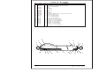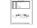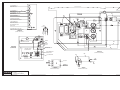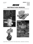
1
Repair Parts
Manual
battery powered
electric
Manufactured 01-97 through 01-01
P/N 0161861
April 1997 - revised Decmber 2001
General information
About this manual:
This repair parts manual covers current production machines only.
While Snorkel has attempted in every way to confirm
that all information in this manual is correct, improvements are being constantly made to the machine that
may not be reflected in this manual.
If you find information in this manual that is not correct,
or is confusing, you are urged to report your findings to
Snorkel for our evaluation.
Your input is important to us and will be used in future
printings of this manual.
Every person who repairs this machine must be qualified and authorized to do so.
CAUTION
DO NOT modify this aerial platform without prior
written consent of Snorkel Engineering Department. Modification may void the warranty, adversely affect stability, or affect the operational
characteristics of the aerial platform.
This machine is covered by a limited warranty that specifically identifies items warrantied by Snorkel and those
items covered by original manufacturers warranty.
NPT . . . . . . . . . . . . . . . . . . . . . . national pipe thread
psi . . . . . . . . . . . . . . . . . . . . . pounds per square inch
qty . . . . . . . . . . . . . . . . . . . . . . . . . . . . . . . . . quantity
UL . . . . . . . . . . . . . . . Underwriters Laboratories Inc.
Electrical Hazard
DANGER
The aerial platform is not electrically insulated.
Death or serious injury can result from contact with,
or inadequate clearance from, an energized
conductor.
Do not go closer than the minimum safe approach
distance as defined by the minimum Safe Approach
Distance as defined by ANSI Standards.
Regard all conductors as energized.
Allow for electrical wire sag and aerial platform sway.
If the work platform, or any part of the aerial platform
contacts a high-voltage electrical conductor, the entire
machine can become electrically charged.
A copy of the Snorkel Limited Warranty is located on the
inside of the back cover of this manual.
If that happens, remain on the machine and do not contact any other structure or object. This includes the
ground, adjacent buildings, poles, and any other objects
that are not part of the aerial platform.
All correspondence relative to this machine, such as
field reports, discrepancy reports, requests for information, etc., should be directed to:
Such contact could make your body a conductor to the
other object, creating an electrical shock hazard resulting in death or serious injury.
Snorkel International, Inc.
P.O. Box 1160
St. Joseph, MO 64502-1160 USA
Phone: (816)-364-0317
http://www.snorkelusa.com
If an aerial platform is in contact with an energized conductor the platform operator must warn ground personnel in the vicinity to stay away. Their bodies can conduct
electricity creating an electrical shock hazard resulting
in death or serious injury.
Abbreviations
Do not approach or leave the aerial platform until the
electricity has been turned off.
The following abbreviations may be used in this manual:
AC. . . . . . . . . . . . . . . . . . . . . . . . . alternating current
ANSI . . . . . . . American National Standards Institute
CCA. . . . . . . . . . . . . . . . . . . . . . . cold cranking amps
cm . . . . . . . . . . . . . . . . . . . . . . . . . . . . . . . centimeter
DC. . . . . . . . . . . . . . . . . . . . . . . . . . . . . direct current
EMS . . . . . . . . . . . . . envelope management system
GFCI . . . . . . . . . . . . . . . . ground fault circuit interrupt
LP . . . . . . . . . . . . . . . . . . . . . . . . . liquified petroleum
LPG . . . . . . . . . . . . . . . . . . . . liquified petroleum gas
mm . . . . . . . . . . . . . . . . . . . . . . . . . . . . . . millimeters
ft . . . . . . . . . . . . . . . . . . . . . . . . . . . . . . . . . . . . . feet
in . . . . . . . . . . . . . . . . . . . . . . . . . . . . . . . . . . . . . inch
lbs . . . . . . . . . . . . . . . . . . . . . . . . . . . . . . . . . pounds
no . . . . . . . . . . . . . . . . . . . . . . . . . . . . . . . . . number
© Snorkel – all rights reserved
Do not attempt to operate the lower controls when the
work platform or any part of the aerial platform is in contact with a high-voltage electrical conductor or if there is
an immediate danger of such contact.
Personnel on or near an aerial platform must be continuously aware of electrical hazards, recognizing that
death or serious injury can result from contact with an
energized conductor.
Printed in USA
Table of Contents
Service and parts information
To order service or repair parts . . . . . . . . . . . . . . . . . . i
ANSI and OSHA compliance . . . . . . . . . . . . . . . . . . . . i
Manuals . . . . . . . . . . . . . . . . . . . . . . . . . . . . . . . . . . . i
Parts order form . . . . . . . . . . . . . . . . . . . . . . . . . . . . . ii
Section 1. - Repair parts
Chassis . . . . . . . . . . . . . . . . . . . . . . . . . . . . . . . . . . 1-2
Steering yoke . . . . . . . . . . . . . . . . . . . . . . . . . . . . . 1-7
Turntable . . . . . . . . . . . . . . . . . . . . . . . . . . . . . . . . . 1-8
Tray, left hand . . . . . . . . . . . . . . . . . . . . . . . . . . . . 1-10
Tray, right hand . . . . . . . . . . . . . . . . . . . . . . . . . . . 1-13
Cowling, left hand . . . . . . . . . . . . . . . . . . . . . . . . . 1-14
Cowling, right hand . . . . . . . . . . . . . . . . . . . . . . . . 1-16
Booms, lower. . . . . . . . . . . . . . . . . . . . . . . . . . . . . 1-18
Booms, upper . . . . . . . . . . . . . . . . . . . . . . . . . . . . 1-21
Platform rotator . . . . . . . . . . . . . . . . . . . . . . . . . . . 1-23
Power trak . . . . . . . . . . . . . . . . . . . . . . . . . . . . . . . 1-24
Platform . . . . . . . . . . . . . . . . . . . . . . . . . . . . . . . . . 1-26
Platform gate . . . . . . . . . . . . . . . . . . . . . . . . . . . . . 1-28
Placards and decals . . . . . . . . . . . . . . . . . . . . . . . 1-30
Swing drive . . . . . . . . . . . . . . . . . . . . . . . . . . . . . . 1-33
Swing drive, Gear Products . . . . . . . . . . . . . . . . . 1-34
Swing drive, Perfection Gear . . . . . . . . . . . . . . . . 1-36
Swing drive, Tulsa Winch . . . . . . . . . . . . . . . . . . . 1-38
Gear hub - Fairfield . . . . . . . . . . . . . . . . . . . . . . . . 1-40
Motor, electric drive . . . . . . . . . . . . . . . . . . . . . . . . 1-42
Section 2. - Hydraulics
Hydraulic hoses. . . . . . . . . . . . . . . . . . . . . . . . . . . . 2-2
Control valve, 3 station . . . . . . . . . . . . . . . . . . . . . . 2-4
Control valve package, 3 station . . . . . . . . . . . . . . . 2-6
Control valve, 5 station . . . . . . . . . . . . . . . . . . . . . . 2-8
Control valve package, 5 station . . . . . . . . . . . . . . 2-10
Accumulator . . . . . . . . . . . . . . . . . . . . . . . . . . . . . 2-12
Extension cylinder . . . . . . . . . . . . . . . . . . . . . . . . . 2-13
Cylinder, extension - GBI . . . . . . . . . . . . . . . . . . . 2-14
Cylinder, extension - Prince . . . . . . . . . . . . . . . . . 2-15
Jib cylinder, GBI or Prince. . . . . . . . . . . . . . . . . . . 2-16
Jib cylinder, Rosenboom . . . . . . . . . . . . . . . . . . . . 2-17
Cylinder, jib - GBI . . . . . . . . . . . . . . . . . . . . . . . . . 2-18
Cylinder, jib - Prince . . . . . . . . . . . . . . . . . . . . . . . 2-19
Cylinder, jib - Rosenboom . . . . . . . . . . . . . . . . . . . 2-20
Main boom lift cylinder . . . . . . . . . . . . . . . . . . . . . 2-21
Cylinder, main boom lift - Green . . . . . . . . . . . . . . 2-22
Cylinder, main boom lift - Prince . . . . . . . . . . . . . . 2-23
Master level cylinder . . . . . . . . . . . . . . . . . . . . . . . 2-24
Cylinder, master level - Green. . . . . . . . . . . . . . . . 2-25
Cylinder, master level - Prince . . . . . . . . . . . . . . . 2-26
Riser lift cylinder - Prince . . . . . . . . . . . . . . . . . . . 2-27
Riser lift cylinder - Rosenboom . . . . . . . . . . . . . . . 2-28
Cylinder, riser lift - Prince . . . . . . . . . . . . . . . . . . . 2-29
Cylinder, riser lift - Rosenboom . . . . . . . . . . . . . . . 2-30
Slave level cylinder before 11-30-2000. . . . . . . . . 2-31
Slave level cylinder after 11-30-2000 . . . . . . . . . . 2-32
Cylinder, slave level - GBI . . . . . . . . . . . . . . . . . . . 2-33
Cylinder, slave level - Prince . . . . . . . . . . . . . . . . . 2-34
ATB 46e – 01-97 through 01-01
Cylinder, slave level - Rosenboom . . . . . . . . . . . . 2-35
Cylinder, steering - Green . . . . . . . . . . . . . . . . . . . 2-36
Cylinder, steering - Prince . . . . . . . . . . . . . . . . . . . 2-37
Emergency power pump . . . . . . . . . . . . . . . . . . . . 2-38
Hydraulic oil filter . . . . . . . . . . . . . . . . . . . . . . . . . . 2-39
Hydraulic platform rotator . . . . . . . . . . . . . . . . . . . 2-40
Hydraulic oil reservoir . . . . . . . . . . . . . . . . . . . . . . 2-42
Section 3. - Electrical
General wiring diagram . . . . . . . . . . . . . . . . . . . . . . 3-2
GE drive control, production units . . . . . . . . . . . . . . 3-5
GE drive control, retrofit units . . . . . . . . . . . . . . . . . 3-6
Electric bulkhead . . . . . . . . . . . . . . . . . . . . . . . . . . . 3-8
Lower control box . . . . . . . . . . . . . . . . . . . . . . . . . 3-11
Upper control box . . . . . . . . . . . . . . . . . . . . . . . . . 3-12
Battery charger, 115 volt . . . . . . . . . . . . . . . . . . . . 3-14
Battery charger, 230 volt . . . . . . . . . . . . . . . . . . . . 3-15
Boom limit switch. . . . . . . . . . . . . . . . . . . . . . . . . . 3-16
Platform foot switch . . . . . . . . . . . . . . . . . . . . . . . . 3-17
Gauge panel . . . . . . . . . . . . . . . . . . . . . . . . . . . . . 3-18
Power to platform, 110 volt . . . . . . . . . . . . . . . . . . 3-19
Contactor, 12 volt DC . . . . . . . . . . . . . . . . . . . . . . 3-20
Section 4. - Factory installed options
Air line to platform . . . . . . . . . . . . . . . . . . . . . . . . . . 4-2
Motion alarm . . . . . . . . . . . . . . . . . . . . . . . . . . . . . . 4-3
Motion alarm, drive . . . . . . . . . . . . . . . . . . . . . . . . . 4-4
Platform lights . . . . . . . . . . . . . . . . . . . . . . . . . . . . . 4-5
Sandblast kit . . . . . . . . . . . . . . . . . . . . . . . . . . . . . . 4-6
Upper control box cover . . . . . . . . . . . . . . . . . . . . . 4-7
Vandalism kit . . . . . . . . . . . . . . . . . . . . . . . . . . . . . . 4-8
Lights, warning . . . . . . . . . . . . . . . . . . . . . . . . . . . . 4-9
Service and parts information
To order service or repair parts
Manuals
When placing an order for service or repair parts, please
have the following information available for your machine.
Manuals are available from Snorkel to support any of the
machines that we produce.
ü Machine model number
ü Machine serial number
ü Snorkel part number
ü Description of part
ü Quantity of parts required
ü Your purchase order number
ü Address for order to “Ship To”
The specific manuals for ATB 46e are as follows:
ü Operator’s Manual
Snorkel part number - 0161457
ü Repair Parts Manual
Snorkel part number - 0161861
ü Troubleshooting Guide
Snorkel part number - 0162737
ü ANSI Manual of Responsibilities
ANSI/SIA A92.5-1992
ü Your desired shipment method
The parts order form on the following page may be
mailed or faxed to the attention of Parts Worldwide at the
following location:
Snorkel International, Inc.
P.O. Box 1160
St. Joseph, MO 64502-1160 USA
Phone: 1-(800)-255-0317
Parts Worldwide Fax: (816)-364-6312
Attention: Parts Department
For your convenience, our electronic on-line ordering
system is available at the following Internet location:
http://www.omniquip.com
ANSI and OSHA compliance
All owners and users of the aerial platform must read,
understand, and comply with all applicable regulations.
Ultimate compliance to OSHA regulations is the responsibility of the user and their employer.
Record machine information here:
Model number
ANSI publications clearly identify the responsibilities of
all personnel who may be involved with the aerial platform. A reprint of the “Manual of Responsibilities for
Dealers, Owners, Users, Operators, Lessors and Lessees of ANSI/SIA A92.5-1992 Boom-Supported Elevating Work Platforms” is available from Snorkel dealers
or from the factory upon request.
Serial number
Copies are also available from:
Purchased from
Scaffold Industry Association
20335 Ventura Blvd. Suite 310
Woodland Hills, CA 91364-2471 USA
ATB 46e – 01-97 through 01-01
Date of purchase
Snorkel dealer or distributor
i
Parts order form
Fill out completely and fax to (816)-364-6312 attention: Parts Worldwide
Date
Model
Company
Serial number
Address
Optional equipment
Purchase order number
Contact name
Ship to
Phone number
Fax number
Account number
Purchase order number
Part number
Ship by
Description
Quantity
Price
Note: Backordered parts will be shipped as soon as available by the same shipping method
as the original order unless indicated below:
Ship complete order only - do not backorder parts.
Ship all available parts and supply information of disposition of backordered parts.
Other instructions as specified
ii
ATB 46e – 01-97 through 01-01
Section 1. - Repair parts
ATB 46e – 01-97 through 01-01
1-1
Chassis
item
1
2
3
4
5
6
7
8
9
10
11
12
13
14
15
16
17
18
19
20
21
22
23
24
25
26
27
28
29
30
31
32
33
34
35
36
37
38
39
40
41
42
43
44
45
46
47
48
49
50
51
52
53
54
55
part no
0150059
0150216
0163168
0160546
0161014
300840
0160560
0162786
0160563
0160564
3040469
986769
5560345
5560689
970889
0162225
562846
970369
970059
3049911
2580010
300542
302324
5035318
25560167
970909
3040269
3040268
238396
0350726
5560283
5569856
302574
5560170
5560035
3040472
7280001
3011203
0160953
25560277
3040691
5560169
5560201
970259
987109
5560609
5560034
987119
970489
970479
986299
5560033
970049
5560004
qty
1
1
1
1
1
1
1
1
2
4
4
1
2
1
2
8
1
1
6
1
1
2
8
2
2
1
16
6
4
1
1
12
3
1
2
1
1
18
1
2
1
1
30
18
8
11
13
14
4
2
4
16
8
6
11
description
Rotation bearing
Cylinder, steering - (see hydraulics section for parts breakdown)
Cable, 10 gauge/2 conductor
Chassis - (consult factory)
Arm, swing stop
Placard, battery disconnect
Lockout lever
Tie rod
Steering yoke - (see page 1-7 for parts breakdown)
Pin, tie rod
King pin
Relay, 12 volt DC
Machine washer
Capscrew 3/4-10 x 3-1/4 inch long hex head grade 5 full thread
Machine bushing 1-1/2 inch OD x 1 inch ID x 14 gauge thick
Capscrew 1/2-13 x 1 inch long hex head grade 5
Fuse block
Relay, 24 volt DC
Capscrew 5/16-18 x 1 inch long hex head grade 5
Capscrew 1/4-20 x 1-1/2 inch long hex head grade 5
DC\DC converter isolator
Thrust washer
Snap ring 1 inch heavy duty
Machine bushing 2-1/4 inch OD x 1-1/2 inch ID x 10 gauge thick
Straight thread 90° elbow
Trimlock 36 inch long
Capscrew 1/2-13 x 1-1/2 inch long hex head grade 5
Insulator boot
Insulator boot
Plug male 125 volt AC
Battery wire, red
Capscrew 5/8-11 x 1-1/2 inch long hex head grade 8 locking
Capscrew 5/16-18 x 3/8 inch long hex head grade 5
Lanyard
Washer 3/4 hard flat ASTM-F436
Nut 3/4-10 self locking
Plug, female 125 volt AC
Lug nut
Wire, 12 gauge/3 conductor x 96 feet long
Latch
Trimlock 48 inch long
Connector
Washer 5/8 hard flat ASTM-F436
Capscrew 5/8-11 x 2-1/2 inch long locking hex head grade 8
Capscrew 5/16-18 x 1 inch long hex head grade 5
Washer 5/16 medium lock
Machine screw #10-24 x 1/2 inch long truss head
Nut #10-24 self locking
Washer 3/8 medium lock
Capscrew 3/8-16 x 1-1/2 inch long hex head grade 5
Capscrew 3/8-16 x 1-1/4 inch long hex head grade 5
Washer 3/8 medium flat
Nut 3/8-16 self locking
Capscrew 1/4-20 x 1 inch long hex head grade 5
Nut 1/4-20 self locking
Parts list continued on next page
1-2
ATB 46e – 01-97 through 01-01
Chassis
item
56
57
58
59
60
61
62
63
64
65
66
67
68
69
70
71
72
73
74
75
76
77
78
79
80
81
82
83
84
85
86
87
88
89
90
91
92
93
94
95
96
97
98
99
100
101
102
103
104
105
part no
7110045
986359
986009
5560648
5560168
5560154
987139
5560031
986019
5093027
970449
5560296
5093000
5093010
5093012
0160500
3040536
0160509
0160510
0160519
0160520
0163063
0163056
0160557
5569819
3020061
0160572
0160573
0160574
0160578
0163068
0160871
0160954
300437
301406
302431
0161388
3049874
5560332
0161646
0161647
0161648
0163192
0162945
5530018
5569013
563156
573564
7200021
0181852
0181853
0181854
0162177
qty
2
8
10
13
4
4
24
14
10
1
4
2
1
1
1
2
4
1
1
2
2
1
1
1
2
1
1
1
1
1
1
1
1
4
2
2
2
1
1
1
1
1
2
2
2
4
8
4
2
1
1
1
1
description
O-ring
Washer 1/2 medium flat
Washer #10 medium flat
Machine screw #10-24 x 3/4 inch long truss head
Washer 1/2 hard flat ASTM-F436
Capscrew 1/2-13 x 1-3/4 inch long hex head grade 8
Washer 1/2 medium lock
Nut 5/16-18 self locking
Washer 1/4 medium flat
Clamp
Capscrew 3/8-16 x 3/4 inch long hex head grade 5
Drive screw #4 x 1/2 inch long PK type U
Clamp
Clamp
Clamp
Gear hub - (see page 1-40 for parts breakdown)
Connector
Bracket, right battery tray
Tray, right battery
Insulator angle
Battery hold down
Cover, rear
Electric bulkhead - (see page 3-6 for parts breakdown)
Bracket, left battery tray
Capscrew, 5/8-11 x 1-1/8 special serrated head
Battery disconnect switch
Cover, right hand end
Cover, left hand end
Striker, left hand battery tray
Tray, left battery
GE drive control - (see page 3-6 for parts breakdown)
Striker, right hand battery tray
Front cover electric
Bearing flanged
Pin tray adjuster
Slide pad
1/4 inch hydraulic hose
DC\DC converter
Rubber strip 1/8 x 1 x 60 inch long
Wire, battery
Wire, battery
Wire, battery
1/2 inch hydraulic hose
Motor, electric drive - (see page 1-42 for parts breakdown)
Extension spring
Grommet
Battery, 6 volt DC - 350 CCA
Battery hold down
Brake, electric drive motor
Lining repair kit
O-ring repair kit
Bearing repair kit
Wire DC/DC transient suppresser
Parts list continued on next page
ATB 46e – 01-97 through 01-01
1-3
Chassis
item
106
107
108
109
110
111
112
113
114
115
116
117
118
119
1-4
part no
0163193
0161408
302807
5569886
0162021
7190007
0150444
0161981
0161643
0160595
3050092
3050093
5035321
5093006
3040452
qty
1
6
2
4
1
1
1
1
2
4
1
1
2
1
2
description1
1/2 inch hydraulic hose
Jumper wire
Jumper wire
Capscrew 1/4-20 x 1-3/4 inch long hex head grade 5
Decal, caution drive motors
Gasket
Battery wire
Plate
Cover, batteries
Tire, foam filled 9.5 x 16.5 - 8 ply
Battery charger, 115 volt - (see page 3-14 for parts breakdown)
Battery charger, 230 volt - (see page 3-15 for parts breakdown)
Straight thread 90° elbow
Clamp
Insulator boot
ATB 46e – 01-97 through 01-01
109
64
55
38
101
95
41
102
56
85
107
79
115
G
100
83
4
117 104
29
51 52
96
53 84
116
18
21
G
99
86 53
52 50
16
57
62
28
19 63
E
113
30
A
A
42
110
94 77
76 E
75
J
63 46
45
J
J
5152
4748
58
53 87
34
48
58
59
82
100
74
73
71
97
41
101
112
J
"+"
103
138
105
"-"
48
58
59
114
107
CURTIS CONVERTOR DETAIL
1
64
46
33
39
37
88
48
47
40
43
44
47
60
61
32
43
91
SECTION A-A
93
105
111
54
55
AWA16184E-2
Chassis
sheet 1
Snorkel model ATB 46e
Page 1 - 5
95
112
96
97
BLK
118
22
RED
31
RED
72
RED
90
23
119
89
28
24
80
5
26
SECTION B-B
9
106
27
62
11
98
108
VIEW F-F
15
23
10
14
35
36
SECTION E-E
49
52
66
78
23
VIEW J-J
23
13
10
SECTION G-G
15
10
23
SECTION C-C
23
13
10
F
B
B
3
25 92
F
64
17
55 20
C
C
12
54
55
64
70
6
7
67
81
47
59
54
55
64
65
BOTTOM VIEW
Page 1 - 6
Chassis
sheet 2
Snorkel model ATB 46e
2
25
10 13 23
8
52
53
69
AWA16184E-3
Steering yoke
item
1
2
3
4
5
6
7
8
9
10
11
12
13
14
part no
qty
0162786
0150599
0160562
0163060
561196
988129
2502229
2540005
2540010
2560005
2560010
5560160
5560161
7150016
8010041
1
1
1
1
1
1
2
1
1
1
1
1
1
1
9
description
Steering yoke
Hub cap
Steering yoke
Steering hub
Bearing
Cotter pin 5/32 inch diameter x 1-3/4 inch long
Bearing
Inner bearing cup
Bearing cup
Outer bearing cone
Bearing cone
Spindle nut
Spindle nut washer
Seal
Stud, lug bolt
4
2
14
13
6
9
5
7
8
3
10
12
11
1
ATB 46e – 01-97 through 01-01
AW0162786
1-7
Turntable
item
1
2
3
4
5
6
7
8
9
10
11
12
13
14
15
16
17
18
19
20
21
22
23
24
25
26
27
28
29
30
31
32
1-8
part no
0161411
0160698
0160699
0162715
0162072
5569012
970479
5560201
5038702
972439
5560033
0050400
0161390
986309
5560303
5569884
5560293
5569890
970929
987139
986299
5569958
0070772
5560306
5560169
970849
984149
986359
5569957
0163169
970889
qty
1
4
1
1
1
1
4
2
20
1
4
14
2
2
6
1
1
4
8
2
4
6
3
1
1
27
6
6
10
3
4
2
description
Swing drive - (see page 1-33 for parts breakdown)
Riser support pad
Riser support
Turntable - (consult factory)
Rear boom rest
Counterweight set
Rubber bumper
Capscrew 3/8-16 x 1-1/4 inch long hex head grade 5
Capscrew 5/8-11 x 2-1/2 inch long locking hex head grade 8
Male 45° elbow
Carriage bolt 3/8-16 x 1-1/4 inch long
Nut 3/8-16 self locking
3/8 inch hydraulic hose
3/8 inch hydraulic hose
Washer hard flat 1-7/8 inch OD x 3/4 inch ID
Capscrew 3/4-10 x 1-3/4 inch long hex head grade 5
Capscrew 3/4-10 x 2-1/2 inch long hex head grade 5
Capscrew 3/4-10 x 2 inch long hex head grade 5
Capscrew screw 3/8-16 x 1 inch long socket flat head
Capscrew 1/2-13 x 2 inch long hex head grade 5
Washer 1/2 medium lock
Washer 3/8 medium flat
Nut 5/8-11 self locking
1/4 inch hydraulic hose
Capscrew 5/8-11 x 4 inch long hex head grade 8 locking
Washer 5/8 hard flat ASTM-F436
Capscrew 1/2-13 x 1-1/4 inch long hex head grade 5
Nut 1/2-13 hex
Washer 1/2 medium flat
Capscrew 5/8-11 x 5-1/4 inch long locking hex head grade 8
Spacer, swing drive - (not used on Tulsa Winch swing drive)
Capscrew 1/2-13 x 1 inch long hex head grade 5
ATB 46e – 01-97 through 01-01
Turntable
16
15
17
22
12
11
RIGHT HAND MODULE
24
10
6
15
22
12
30
25
19
12
2
18
26
85
3
31
1
2
1912
1815
SEE DETAIL A
23
25
26
6
20
21
29
15
18
21
29
32
9
26
23
26
DETAIL A
SWING DRIVE MOUNTING
30
31
LEFT HAND MODULE
4
7
27
28
29
11
12
27
22
28
29
AWA16022J
ATB 46e – 01-97 through 01-01
1-9
Tray, left hand
item
1
2
3
4
5
6
7
8
9
10
11
12
13
14
15
16
17
18
19
20
21
22
23
24
25
26
1 - 10
part no
0070789
0072957
0110732
0163194
0160881
0162392
0162548
0400497
3080022
986269
970469
986299
5035306
5035705
987119
986019
5037006
970259
6020075
5560031
3080029
972569
5560004
970479
5560033
5569888
qty
1
1
1
1
1
1
1
1
1
9
2
12
1
1
2
4
1
4
1
3
1
4
4
4
4
3
description
3/8 inch hydraulic hose
1/2 inch hydraulic hose
1/2 inch hydraulic hose
1/2 inch hydraulic hose
Tray, left hand
Backwall, left hand
Hydraulic oil reservoir - (see page 2-42 for parts breakdown)
3/4 inch hydraulic hose
Motor, 48 volt DC - 4 horsepower
Washer 5/16 medium flat
Capscrew 3/8-16 x 1 inch long hex head grade 5
Washer 3/8 medium flat
Straight thread 90° elbow
Straight thread 45° elbow
Washer 3/8 medium lock
Washer 1/4 medium flat
Swivel nut 90° elbow
Capscrew 5/16-18 x 1 inch long hex head grade 5
Hydraulic gear pump
Nut 5/16-18 self locking
Motor controller
Carriage bolt 1/4-20 x 3/4 inch long
Nut 1/4-20 self locking
Capscrew 3/8-16 x 1-1/4 inch long hex head grade 5
Nut 3/8-16 self locking
Carriage bolt 5/16-18 x 1 inch long
ATB 46e – 01-97 through 01-01
23
22
16
4
6
8
21
7
7
TO HYDRAULIC RETURN FILTER
19
9
19
10 11 20
14
13
3
9
17
20
18
10
TO 3 STATION
VALVE
TO EMERGENCY
POWER PUMP
2
1
10
15
24
5
TO 3 STATION VALVE
12
24
25
AWA16003
Tray, left hand
Snorkel model ATB 46e
Page 1 - 11
31
23
13
4
7
12 17
33
18
35
37
34
11 16
36
3
8
12
32
35
39
38
16
35
14
12
31
30
23
39
16
15
26
11
41
6
10
42
23 30
40
5
25
27
28
21
24
31
2
16 38 39
12
14
9
1
12
22
35
Tray, right hand
Page 1 - 12
Snorkel model ATB 46e
29
16
19
38
39
43
16
20
38
39
44
45
46
AWA16005O
Tray, right hand
item
1
2
3
4
5
6
7
8
9
10
11
12
13
14
15
16
17
18
19
20
21
22
23
24
25
26
27
28
29
30
31
32
33
34
35
36
37
38
39
40
41
42
43
44
45
46
part no
0160979
0162389
0161148
0161306
0161368
0161255
3050002
3020202
0161644
5093013
970029
5560031
970479
970259
970049
5560004
0150910
0150813
3040506
3040193
970469
5569888
986299
987119
0161672
0161247
3040127
5560288
3040469
970469
5560033
970269
5074401
5037102
986269
5560341
0150811
972569
986019
0161920
0161463
5093014
0071959
987109
984099
5560038
qty
1
1
1
1
1
1
1
1
1
1
11
9
2
2
1
14
2
1
1
1
2
3
7
2
1
1
1
1
1
5
7
2
1
1
5
5
1
7
9
1
1
2
1
2
2
2
description
Tray, right hand
Backwall, right hand
Mount, lower controls
Battery stop
Emergency power pump - (see page 2-38 for parts breakdown)
Control valve, 3 station - (see page 2-6 for parts breakdown)
Battery, 12 volt DC - 550 CCA
Tilt alarm 5°, 1 second delay
Hydraulic oil filter - (see page 2-39 for parts breakdown)
Clamp
Capscrew 1/4-20 x 3/4 inch long hex head grade 5
Nut 5/16-18 self locking
Capscrew 3/8-16 x 1-1/4 inch long hex head grade 5
Capscrew 5/16-18 x 1 inch long hex head grade 5
Capscrew 1/4-20 x 1 inch long hex head grade 5
Nut 1/4-20 self locking
Battery hold down bolt
Battery hold down angle
Solenoid, 12 volt DC
Contactor, 48 volt DC
Capscrew 3/8-16 x 1 inch long hex head grade 5
Carriage bolt 5/16-18 x 1 inch long
Washer 3/8 medium flat
Washer 3/8 medium lock
Gauge panel - (see page 3-18 for parts breakdown)
Lower control box - (see page 3-11 for parts breakdown)
Horn, 12 volt DC
Capscrew 1/4-20 x 1/2 inch long hex washer head self tapping
Relay, 12 volt DC
Capscrew 3/8-16 x 1 inch long hex head grade 5
Nut 3/8-16 self locking
Capscrew 5/16-18 x 1-1/4 inch long hex head grade 5
Bulkhead locknut
Bulkhead connector
Washer 5/16 medium flat
Washer 1/4 star tooth lock
Insulator angle
Carriage bolt 1/4-20 x 3/4 inch long
Washer 1/4 medium flat
Accumulator - (see page 2-12 for parts breakdown)
Wire harness, turntable valves
Clamp
Jumper wire
Washer 5/16 medium lock
Nut 5/16-24 hex
Nut #10-32 self locking
ATB 46e – 01-97 through 01-01
1 - 13
Cowling, left hand
item
1
2
3
4
5
6
7
8
9
10
11
12
13
14
1 - 14
part no
0160881
0160986
0162480
986269
970259
0162392
0162388
0160992
5569888
5560372
5560031
970239
5510014
0161338
qty
description
1
1
1
21
4
1
1
1
2
13
24
6
1
1
Tray, left hand
Top sheet, left hand
Front post, left hand
Washer 5/16 medium flat
Capscrew 5/16-18 x 1 inch long hex head grade 5
Backwall, left hand
Band
Door, left hand
Carriage bolt 5/16-18 x 1 inch long
Carriage bolt 5/16-18 x 3/4 inch long
Nut 5/16-18 self locking
Capscrew 5/16-18 x 3/4 inch long hex head grade 5
Latch, sealed lever
Bracket
ATB 46e – 01-97 through 01-01
Cowling, left hand
14
11
9
4
8
11
10
4
11
10
4
2
12
11
4
11
10
11
10
3
7
10
4
6
4
4
5
11
ATB 46e – 01-97 through 01-01
1
13
5
11
AWA16008
1 - 15
Cowling, right hand
item
1
2
3
4
5
6
7
8
9
10
11
12
13
14
1 - 16
part no
0160979
0160985
970239
0161338
0162383
0160996
0162386
0160990
5560372
970259
5560031
5569888
5510014
986269
qty
description
1
1
6
1
1
1
1
1
5
2
20
7
1
19
Tray, right hand
Top sheet, right hand
Capscrew 5/16-18 x 3/4 inch long hex head grade 5
Bracket
Front post, right hand
Backwall, right hand
Band
Door, right hand
Carriage bolt 5/16-18 x 3/4 inch long
Capscrew 5/16-18 x 1 inch long hex head grade 5
Nut 5/16-18 self locking
Carriage bolt 5/16-18 x 1 inch long
Latch, sealed lever
Washer 5/16 medium flat
ATB 46e – 01-97 through 01-01
Cowling, right hand
11 12
14
4
8
11
9
14
11
9
2
11
9
3 11
14
7
6
14
12
11
11
12
14
5
ATB 46e – 01-97 through 01-01
13
1
10
11
14
AWA16009
1 - 17
Booms, lower
item
1
2
3
4
5
6
7
8
9
10
11
12
13
14
15
16
17
18
19
20
21
22
23
24
25
26
27
28
29
30
31
32
33
34
35
36
37
38
39
40
41
42
43
1 - 18
part no
0160725
0161046
0160685
0160625
0160681
0160656
0161185
0161188
0160823
0150045
0160643
0160698
0160748
0160749
0160750
0162798
0160752
0160754
0160755
0160756
0160757
0160758
0160946
0160947
0160763
0160764
0160972
5590026
5590027
5591100
300729
0160976
0160977
5560683
987119
986299
2500048
561116
972559
5560033
970469
974749
5560034
qty
1
1
1
1
1
1
1
1
1
1
1
1
2
1
1
1
1
3
1
3
1
1
1
1
16
12
4
12
16
4
28
1
1
6
10
6
16
4
2
2
4
2
2
description
Riser bracket
Floating turret
Bottom arm
Top arm
Bottom follower bar
Top follower bar
Riser lift cylinder - (see hydraulics section for parts breakdown)
Main boom lift cylinder - (see hydraulics section for parts breakdown)
Bracket, master level cylinder
Cylinder, master level - (see hydraulics section for parts breakdown)
Timing link
Riser support pad
Pin
Pin
Pin
Boom limit switch - (see page 3-16 for parts breakdown)
Pin
Pin
Pin
Pin
Pin
Pin
Pin
Pin
Pin lock
Pin lock
Pin lock
Retaining ring
Retaining ring
Snap ring
Capscrew, special
Top channel, hose guide
Bottom channel, hose guide
Capscrew 3/8-16 x 5/8 inch long hex head grade 5
Washer 3/8 medium lock
Washer 3/8 medium flat
Bearing
Bearing
Capscrew 3/8-16 x 1 inch long socket flat head
Nut 3/8-16 self locking
Capscrew 3/8-16 x 1 inch long hex head grade 5
Machine screw #10-24 x 1-3/4 inch long round head
Nut #10-24 self locking
ATB 46e – 01-97 through 01-01
18 25 29
31
31 29
14 25
D
29 31
31
G
3128
26
19 26
25 18
29
25
13
21
28 31
SECTION A-A
2
SECTION B-B
8
37
4
G
35
34
32
40
39
12
43
42
16
E
B
D
13
25
29
31
20
18
C
25
29
31
31
38 11
F
6
37
26
28
1
E
SECTION F-F
SECTION C-C
F
37
5
20
26
28
31
A
C
B
31 29
3
37
7
33
34
35
31 28
SECTION E-E
24 27 30
25 15
26 22
17
25
29
35 41
9
31
10
23 27 30 35
41
A
SECTION D-D
VIEW G-G
AWA16013
Booms, lower
Snorkel model ATB 46e
Page 1 - 19
69
56
44
34
47
46
45
29
48
47
46
51
50
49
55
50
18
65
55
51
33
5
B
7
34
35
C
A
27
70
39
22
20
11
B
A
C
24
26
68
74
30
40
46
50
71
19
50
51
70
58
57
37
43
46
52
54
50
55
51
65
67
28
73
59
25
9
32
61 62 63
51 50
49 31
8
41
16
72
38
4
3
2
33
42
35
66
60
36
34
1
75
10
6
7
34
35
50
51
70
21
22
29
70
12
14
51 64
23
65
13
17
7150
41
46
46 40
SECTION A-A
Booms, upper
Page 1 - 20
Snorkel model ATB 46e
50
51
53
65
70
SECTION B-B
15
SECTION C-C
50
55
AWA16014
Booms, upper
item
2
3
4
5
6
7
8
9
10
11
12
13
14
15
16
17
18
19
20
21
22
23
24
25
26
27
28
29
30
31
32
33
34
35
36
37
38
39
40
41
42
43
44
45
46
47
48
49
50
part no
0070838
0071272
0161766
0160759
0160760
0160765
0160781
0161526
0160804
0161865
0160844
0160847
0160863
0160864
0160866
0160867
0160944
0160945
0160948
0160949
0160972
0161005
0161023
0161044
0161186
0161187
0162795
0161189
0161203
0161223
0161307
0161866
0161427
300729
302323
5560030
5560281
5560197
5591100
5093001
5093004
0160903
0161374
0160751
970219
986269
987109
970289
5560683
987119
qty
4
4
4
4
1
10
1
1
1
1
1
1
1
1
1
1
1
1
1
1
4
6
1
1
1
1
1
1
1
1
1
1
1
12
10
1
1
6
4
2
4
1
1
1
2
15
6
4
6
32
description
Slide pad shim, .030 inch thick
Slide pad shim, .063 inch thick
Slide pad
Pin
Pin
Pin lock
Platform mounting bracket, lower
Platform rotator - (see page 1-23 for parts breakdown)
Jib end bracket
Jib arm
Inner boom
Base boom
Slide block, extend cylinder
Slide pad
Slide pad
Plate, slide mount
Bottom channel
Slide channel
Pin
Pin
Pin lock
Slide pad retainer plate
Rotary mount bracket
Platform mounting bracket, upper
Extension cylinder - (see page 2-13 for parts breakdown)
Jib cylinder, GBI or Prince - (see page 2-16 for parts breakdown)
Jib cylinder, Rosenboom - (see page 2-17 for parts breakdown)
Slave level cylinder - (see hydraulic section for parts breakdown)
Cover, control valve
Control valve, 5 station - (see page 2-8 for parts breakdown)
Channel, jib hose carrier
Jib arm with standoffs
Power teak - (see page 1-24 for parts breakdown)
Capscrew, special
Retaining ring
Nut 1-1/4-12 self locking
Capscrew 1-8 x 12 inch long hex head grade 5
Set screw 3/8-16 x 1 inch long hex socket flat point
Snap ring
Clamp
Clamp
Hose guide channel
Boom switch flag
Pin
Capscrew 5/16-18 x 1/2 inch long hex head grade 5
Washer 5/16 medium flat
Washer 5/16 medium lock
Capscrew 5/16-18 x 1-3/4 inch long hex head grade 5
Capscrew 3/8-16 x 5/8 inch long hex head grade 5
Washer 3/8 medium lock
Parts list continued on next page
ATB 46e – 01-97 through 01-01
1 - 21
Booms, upper
item
51
52
53
54
55
56
57
58
59
60
61
62
63
64
65
66
67
68
69
70
71
72
73
74
1 - 22
part no
986299
5560031
5560106
970229
970469
0160763
5560172
984239
970889
5560039
5560195
5560169
5560051
5560644
5560033
5569889
970489
5560168
5590027
970449
970426
5560611
987139
5560302
qty
description
24
2
2
4
20
2
2
1
6
1
4
4
4
6
14
1
4
4
2
9
2
6
6
4
Washer 3/8 medium flat
Nut 5/16-18 self locking
Capscrew 3/8-16 x 2-3/4 inch long hex head grade 5
Capscrew 5/16-18 x 5/8 inch long hex head grade 5
Capscrew 3/8-16 x 1 inch long hex head grade 5
Pin lock
Washer 1 inch medium flat
Nut 1-8 hex
Capscrew 1/2-13 x 1 inch long hex head grade 5
Nut 1/2-13 self locking
Capscrew 5/8-11 x 2-1/2 inch long hex head grade 5
Washer 5/8 hard flat ASTM-F436
Capscrew 5/8-11 self locking - (torque 180 ft lbs)
Capscrew 3/8-16 x 1-1/4 inch long socket flat head
Nut 3/8-16 self locking
Capscrew 1/2-13 x 1-3/4 inch long self locking
Capscrew 3/8-16 x 1-1/2 inch long hex head grade 5
Washer 1/2 hard flat ASTM-F436
Retaining ring
Capscrew 3/8-16 x 3/4 inch long hex head grade 5
Capscrew 3/8-16 x 7/8 inch long hex head grade 5
Nut 3/8-16 hex jam
Washer 1/2 medium lock
Capscrew 1/2-13 x 2 inch long self locking
ATB 46e – 01-97 through 01-01
Platform rotator
item
1
2
3
4
5
6
part no
0161526
0161808
5065703
5037003
5035303
6018912
6010794
978419
qty
1
1
1
2
1
1
1
3
description
Platform rotator
Hydraulic platform rotator - (see page 2-40 for parts breakdown)
Straight thread adapter
Swivel nut 90° elbow
Straight thread 90° elbow
Dual counterbalance valve - (factory preset, do not reset)
Replacement cartridge
Capscrew 1/4-20 x 1-1/2 inch long socket head
1
6 – Torque to 10 1/2 ft. lbs.
5
4 3
2 4
Torque to 30-35 ft. lbs.
ATB 46e – 01-97 through 01-01
AW0161526
1 - 23
Power trak
item
1
2
3
4
5
6
7
8
9
10
11
12
13
14
15
16
17
18
19
20
21
22
23
24
25
26
1 - 24
part no
0161427
9920026
0160943
9920028
9920027
970239
986269
5560031
5560674
0161416
0071510
0161333
0150315
0161864
0161335
0161488
0161464
0163067
3011203
0160909
5569890
5560033
0160897
970259
970299
0161627
0161868
qty
1
20
1
1
1
4
10
10
6
2
4
2
2
1
2
1
1
1
1
1
2
2
1
2
2
1
1
description
Power trak
Power track link
Top channel
Mounting bracket, male
Mounting bracket, female
Capscrew 5/16-18 x 3/4 inch long hex head grade 5
Washer 5/16 medium flat
Nut 5/16-18 self locking
Capscrew 5/16-18 x 1-1/2 inch long hex head grade 5
Clamp bar
Spacer, air cleaner
1/4 inch hydraulic hose
1/4 inch hydraulic hose
Slide block shim
1/4 inch hydraulic hose
Wire harness, boom - 12 gauge/8 conductor
Wire harness, boom - 18 gauge/12 conductor
Wire harness, boom - 18 gauge/19 conductor
Wire, 12 gauge/3 conductor x 66 feet long
Side block
Machine screw 3/8-16 x 1 inch long socket flat head
Nut 3/8-16 self locking
Tip end bracket
Capscrew 5/16-18 x 1 inch long hex head grade 5
Capscrew 5/16-18 x 2 inch long hex head grade 5
Wire harness, electric circuit
Hose clamp
ATB 46e – 01-97 through 01-01
11
7
6
5
2
4
6
7
8
26
24
7
6
10
9
23
10
12
22
9
7
6
HOSES
14
14
HOSES
15
19
13
20
21
1
16
3
WIRES
17
WIRES
18
25
AW0161427
Power trak
Snorkel model ATB 46e
Page 1 - 25
Platform
item
1
2
3
4
5
6
7
8
9
10
11
12
13
14
15
16
17
18
19
20
21
22
23
1 - 26
part no
0161652
5560033
970529
986299
5093013
986019
978629
0161680
5093004
970029
984069
987099
3040110
3040116
480652
0101397
7050003
0070709
970909
986359
984069
qty
1
1
1
6
4
8
2
14
2
1
1
7
7
2
1
1
1
1
2
1
6
12
6
description
Platform - (consult factory)
Platform gate - (see page 1-28 for proper platform gate)
Upper control box handrail
Nut 3/8-16 self locking
Capscrew 3/8-16 x 2-1/2 inch long hex head grade 5
Washer 3/8 medium flat
Clamp
Washer 1/4 medium flat
Capscrew 1/4-20 x 1/2 inch long hex head self tapping
Platform foot switch - (see page 3-17 for parts breakdown)
Clamp
Capscrew 1/4-20 x 3/4 inch long hex head grade 5
Nut 1/4-20 hex
Washer 1/4 medium lock
Connector locknut
Connector
Siren, tilt alarm
Document tube
Cap, document tube
Jumper wire
Capscrew 1/2-13 x 1-1/2 inch long hex head grade 5
Washer 1/2 medium flat
Nut 1/2-13 hex
ATB 46e – 01-97 through 01-01
Platform
14
13
12
8
19
18
16
15
20
8
12
13
3
17
45
6
7
89
12
13
14
11
8
10
21
22
23
21
22
23
2
A
A
1
ATB 46e – 01-97 through 01-01
AWM00237
1 - 27
Platform gate
item
1
2
3
4
5
6
7
8
9
10
11
12
13
14
15
16
17
1 - 28
part no
qty
description
016117728
0161177
0161182
0161184
970519
5560033
1
1
2
2
2
2
Gravity gate for 5, and 6 foot aluminum platforms
Gravity gate service kit - (kit includes items 1 through 5)
Gravity gate, aluminum platform
Roller, aluminum gravity gate
Roller spacer, aluminum gravity gate
Capscrew 3/8-16 x 2-1/4 inch long hex head grade 5
Nut 3/8-16 self locking
0160970
2667500
2572007
5560056
0071837
0322724
0161472
987099
984529
970099
986019
300891
1
1
2
1
1
1
1
2
3
3
1
1
Swinging gate for 5, and 6 foot aluminum platforms
Swinging gate, aluminum platform
Knob, gate hinge pin
Bearing
Roll pin 1/8 inch diameter x 1 inch long
Torsion spring
Pin, gate hinge
Latch stop
Washer 1/4 medium lock
Nut sert 1/4-20
Capscrew 1/4-20 x 5/8 inch long hex head grade 5
Washer 1/4 medium flat
Door latch
ATB 46e – 01-97 through 01-01
Platform gate
1
2
5
4
3
Gravity gate, aluminum platform
6
7
12
8
9
13
10
14
15
16
15
14
17
Door latch
rear view
11
Gate pin
Rear view
Swinging gate, aluminum platform
ATB 46e – 01-97 through 01-01
AWM00238
1 - 29
Placards and decals
item
1
2
3
4
5
6
7
8
9
10
11
12
13
14
15
16
17
18
19
20
21
22
23
24
25
26
27
28
29
30
31
32
33
34
35
36
37
38
39
40
41
42
43
44
45
46
1 - 30
part no
560239
0071425
5560655
0071927
0072277
0072531
0073224
0073298
0073585
0074209
0150448
0150452
0150602
5560080
451986
0151917
0101384
0162551
0070901
0161205
0181562
0161819
5560285
0323896
0323897
0323899
0161329
0150606
0070921
0162337
0083427
0074311
0073492
7030004
0162924
0161178
0161215
0163173
0161213
416836
461066
0181655
467376
0162280
0161699
0161699
qty
2
1
14
1
2
1
1
2
2
1
1
1
1
4
4
1
1
2
2
1
2
1
1
1
2
1
2
1
1
1
1
4
5
1
2
1
2
2
1
1
1
1
1
2
1
1
1
description
Decal, Snorkel brand logo
Placard, platform identification
Pop rivet #AD32-ABS
Decal, hydraulic oil
Placard, lug nut torque
Decal, danger electrical hazard
Decal, notice manual reorder
Placard, danger foam filled tires
Decal, made in USA
Placard, pre-start instructions
Placard, platform capacity - (consult factory)
Decal, attach fall restraint
Decal, directional arrows forward/reverse
Decal, danger descending boom
Bumper
Placard, danger do not alter switch
Decal, directional arrows
Decal, lug nut torque
Decal, Snorkel brand logo
Placard, caution serial number
Placard, danger electrical hazard
Placard, ANSI standard
Decal, emergency lowering procedures
Trimlock 60 inch long
Decal, danger electrical hazard
Decal, danger you must not operate
Decal, danger electrical hazard
Decal, patents applied for
Decal, 125 volt 15 amp power to platform
Placard, 125 volts 15 amps
Decal, emergency lowering procedures
Decal, lift/tie down symbol
Decal, danger cylinder failure - (1 per cylinder)
Decal, rotate while greasing
Decal, OmniQuip logo
Decal, lift/tie down location
Decal, ATB 46e logo
Decal, battery service instructions
Decal, battery charging instructions
Decal, danger electrical hazard
Decal, battery charge - (115 volt charger)
Decal, battery charge - (230 volt charger)
Decal, caution move control handle slowly
Decal, EE logo
Placard, turn key off
Decal, Caution do not run engine - (used with sandblast option)
Decal, Caution do not run engine - (used with air line to platform option)
ATB 46e – 01-97 through 01-01
Placards and decals
29
3
40
13
39
17
8
8
15
19
14
16
14
14
21
21
9
37
18
5
32
27
38
35
27
43
32
14
35
28
25
3 20
25
22
ATB 46e – 01-97 through 01-01
41
AWA16015V-2
1 - 31
Placards and decals
42
23
C
C
45
7
12
46
6
37
33
1
3
11
24
2
3
26
19
36
43
38
9
31
10
4
30
3
44
VIEW C-C
LOWER CONTROLS
34
1 - 32
AWA16015V-3
ATB 46e – 01-97 through 01-01
Swing drive
item
1
2
3
4
5
6
7
part no
qty
0161411
0160545
1
1
6030026
8230073
7110152
987439
5560087
5037005
5065726
1
1
1
2
2
2
2
description
Swing drive, complete
Swing drive
(see page 1-34 for Gear Products swing drive
(see page 1-36 for Perfection Gear swing drive)
(see page 1-38 for Tulsa Winch swing drive)
Swing drive motor
Seal repair kit
O-ring
Washer 1/2 medium lock
Capscrew 1/2-13 x 1-1/4 inch long self locking
Swivel nut 90° elbow
Straight thread adapter
2
5
4
3
6
A
7
B
1
Oil level
fill plug
Oil level
fill plug
AWV0161411
ATB 46e – 01-97 through 01-01
1 - 33
Swing drive, Gear Products
item
1
2
3
4
5
6
7
8
9
10
11
12
13
14
15
16
17
18
19
20
21
22
23
24
25
26
27
28
29
30
31
32
33
34
35
36
1 - 34
part no
0160545
0151004
0162638
0162639
8070216
0162641
0162642
0162643
0162644
0162645
8070252
8070002
0162648
0162649
0162650
0162651
0162652
0162653
0162654
8070262
0162656
0162657
0163038
0162659
8070214
0162661
0163039
0163026
0162662
970889
988199
7190005
0162664
0162747
970469
970849
5560169
5560168
qty
1
1
1
1
1
1
4
1
1
1
1
1
1
1
1
2
2
1
1
1
1
1
1
1
1
3
1
1
2
1
1
1
1
6
4
6
4
description
Swing drive, Gear Products
Seal repair kit - (kit includes items 18, 19, 21, 23, 30, 31 and 32)
Main housing
Cover
Worm gear
Retainer bearing
Worm gear
Shim, .005 inch thick
Spacer
Spacer
Output shaft
Castel nut
Bearing cone
Bearing cup
Bearing cone
Bearing cup
Bearing cone
Bearing cup
Ball bearing
Oil seal
Oil seal
Bushing
O-ring
Snap ring
O-ring
Grease zerk
Hex plug
Cover - (not a service part, used for shipping only)
Vent plug
Capscrew 1/2-13 x 1 inch long hex head grade 5
Cotter key 1/8 inch diameter x 1-1/2 inch long
Gasket
Shim, 1/64 inch thick
Shim, 1/32 inch thick
Capscrew 3/8-16 x 1 inch long hex head grade 5
Capscrew 1/2-13 x 1-1/4 inch long hex head grade 5
Washer 5/8 hard flat ASTM-F436
Washer 1/2 hard flat ASTM-F436
ATB 46e – 01-97 through 01-01
Swing drive, Gear Products
1
2
30
26
Used for
shipping only
4
18
28
34
36
21
14
22
13
6
12
11
25
5
31
32
20
27
25
29
24
9
10
17
23
19
15
ATB 46e – 01-97 through 01-01
8
16
3
25
7
2
33
35
AWV00283
1 - 35
Swing drive, Perfection Gear
item
1
2
3
4
5
6
7
8
9
10
11
12
13
14
15
16
17
18
19
20
21
22
23
24
25
26
27
28
29
1 - 36
part no
0160545
0163022
0163001
0163002
0163003
0163004
0163005
0163006
0172035
0172036
0163007
0163008
0163009
0163010
0163011
0163012
0163013
0163014
0163015
0163016
0163017
0163018
0163019
0172049
0172048
0172047
0112307
0172053
0163020
0163021
0172054
qty
1
1
1
1
1
1
1
1
2
2
1
1
1
1
1
1
6
1
1
2
2
2
2
2
2
2
2
1
4
1
1
description
Swing drive, Perfection Gear
Seal repair kit - (kit includes items 10, 13, and 18 through 25)
Housing
Gear cap
Snap ring
Worm gear
Worm
Motor adapter
Bearing cup
Bearing cone
Pinion
Oil seal
Bearing cone
Bearing cup
Oil seal
Spacer
Capscrew 7/16-14 x 1-1/8 inch long hex head grade 5
Bearing cup
Bearing cone
Shim, .010 inch thick
Shim. .0075 inch thick
Shim, .005 inch thick
Shim, .003 inch thick
Shim, .0075 inch thick
Shim, .005 inch thick
Shim, .003 inch thick
Oil seal
Pressure vent plug
Capscrew 3/9-16 x 1 inch long socket head
Grease fitting, 1/8 NPT 90°
Reducer bushing
ATB 46e – 01-97 through 01-01
Swing drive, Perfection Gear
1
13
25
8
2
6
26
5
22
23
24
7
28
4
16
17
3
2
29
15
18 19
20 21
14
12
11
10
9
AWV00315
ATB 46e – 01-97 through 01-01
1 - 37
Swing drive, Tulsa Winch
item
1
2
3
4
5
6
7
8
9
10
11
12
13
14
15
16
17
18
19
20
21
22
23
24
25
26
27
1 - 38
part no
0160545
8200058
8200021
8200022
8200023
8200024
8200025
8200026
8200027
8200028
8200029
8200030
970239
8200032
8200033
8200034
8200035
8200036
8200037
8200038
8200039
8200040
8200041
970889
8200043
8200044
8200042
8200031
qty
1
1
2
2
1
1
1
1
1
1
1
1
6
1
2
2
2
1
2
1
2
1
3
2
2
2
3
1
1
description
Swing drive, Tulsa Winch
Seal repair kit - (kit includes items 7, 10, 19 and 26)
Bearing cup
Oil fill plug 3/8 NPT hex socket
Output shaft
Housing
Protector - (not a service part, used for shipping only)
Cover
Oil seal
Worm
Gear
O-ring
Capscrew 5/16-18 x 3/4 inch long hex head grade 5
Bushing
Thrust washer
Key
Bearing cone
Grease fitting
Bearing cone
Breather
Gasket
End cap
Lockwasher
Capscrew 1/2-13 x 1 inch long hex head grade 5
Bearing cup
Capscrew - (not a service part, used for shipping only)
Locknut
Oil seal
Pipe bushing
ATB 46e – 01-97 through 01-01
Swing drive, Tulsa Winch
11
2
6
4
24
Used for
shipping only
18
20
27
26
5
Used for
shipping only
22
19
8
19
23
17
2
10
25
21
6
1
15 1
15
11
21
25
16
12
14
3
7
13
9
4
2
ATB 46e – 01-97 through 01-01
AWV00285
1 - 39
Gear hub - Fairfield
item
1
2
3
4
5
6
7
8
9
10
11
12
13
14
15
16
17
18
19
20
21
22
23
24
25
26
27
28
29
30
31
32
33
34
35
36
37
1 - 40
part no
0160500
8060144
8060150
8060146
8060147
8060148
8060145
8060149
8060164
8060143
8060158
8050155
8060161
8060160
8060154
8060153
8060156
8060166
8060157
8060151
8060179
8060170
8060177
8060178
8060176
8060159
8060152
8060162
8060168
8060173
8060172
8060165
8060174
8060171
8060169
8060163
8060167
8060175
qty
1
1
1
1
2
1
1
1
1
9
1
1
96
3
6
3
3
3
1
1
1
1
1
2
1
2
1
1
3
1
1
1
1
1
2
1
4
1
description
Gear hub - Fairfield
Spindle
Lip seal
Bearing cone
Bearing cup
Bearing cone
Housing
Thrust washer
Retaining ring, external
Stud
Ring gear
Carrier
Needle bearing
Thrust spacer
Washer, flat tanged
Planet shaft
Cluster gear
Roll pin
Internal gear
O-ring
O-ring
Input shaft
Disengage cap
Bolt, hex head
Disengage rod
Thrust washer
Sun gear
Thrust washer
Bolt, flat head hex socket
Spring
Thrust washer
Retaining ring, internal
Retaining ring, external
Coupling
Pipe plug
Plate
Drive screw
Retaining ring, internal
ATB 46e – 01-97 through 01-01
Gear hub - Fairfield
2
15
14
12
20
17
23
16
12
18
22
24
13
14
34
25
26
28
25
11
35
36
30
26
27
29
32
3
8
7
21
27
31
19
6
9
5
2
1
4
33
37
ATB 46e – 01-97 through 01-01
AWV00286
1 - 41
Motor, electric drive
item
1
2
3
4
5
6
7
8
9
10
11
12
13
14
part no
0162945
0163052
0163053
0163061
969989
974429
984089
986009
986019
987099
987109
3020222
3080038
5560034
5560673
qty
description
1
1
1
1
1
5
4
2
1
1
4
1
1
2
2
Motor, electric drive
Speed sensor wheel
Speed sensor hub
Speed sensor bracket
Capscrew 1/4-20 x 1-3/4 inch long hex head grade 5
Machine screw #8-32 x 3/8 inch long round head
Nut 5/16-18 hex
Washer #10 medium flat
Washer 1/4 medium flat
Washer 1/4 medium lock
Washer 5/16 medium lock
Speed sensor hall effect
Electric motor
Nut #10-24 self locking
Machine screw #10-24 x 1 inch long truss head
10
6
11
12
14
7
13
5
3
5
9
2
84
1
1 - 42
AW0162945
ATB 46e – 01-97 through 01-01
Section 2. - Hydraulics
ATB 46e – 01-97 through 01-01
2-1
Hydraulic hoses
item
1
2
3
4
5
6
7
8
9
10
11
12
13
14
15
16
17
2-2
part no
0110907
0110732
0161378
0400497
0161395
0161390
0161388
0050400
0161393
0161394
0161399
0161398
0070789
0020280
0070765
0111287
0151171
qty
1
1
1
1
2
2
2
2
1
1
2
2
1
1
2
2
1
description
3/4 inch hydraulic hose
1/2 inch hydraulic hose
3/8 inch hydraulic hose
3/4 inch hydraulic hose
3/8 inch hydraulic hose
3/8 inch hydraulic hose
1/4 inch hydraulic hose
3/8 inch hydraulic hose
1/4 inch hydraulic hose
1/4 inch hydraulic hose
3/8 inch hydraulic hose
3/8 inch hydraulic hose
3/8 inch hydraulic hose
1/4 inch hydraulic hose
1/4 inch hydraulic hose
1/4 inch hydraulic hose
1/2 inch hydraulic hose
ATB 46e – 01-97 through 01-01
EXTEND CYLINDER
SLAVE LEVEL CYLINDER
BOOM LIFT CYLINDER
MASTER LEVEL CYLINDER
10
9
SWING MOTOR
JIB CYLINDER
PLATFORM ROTATOR
STEER CYLINDER
RISER LIFT CYLINDER
POWER TRAK HOSES
8
8
7
POWER TRAK HOSES
12
12
11
6
7
11
SWING
STEER
RISER LIFT
6
LEFT
MOTOR
EXTEND
BOOM LIFT
JIB
PLATFORM ROTATE
16
LEVEL
RIGHT
MOTOR
15
15
14
ACCUMULATOR
CHARGE TO
300 PSI
3
16
17
SYSTEM PUMP
13
5
EMERGENCY POWER
5
4
1
2
AWA16026
Hydraulic hoses
Snorkel model ATB 46e
Page 2 - 3
Control valve, 3 station
item
1
2
3
4
5
6
7
8
9
10
11
12
13
14
15
16
17
2-4
part no
0161255
6010932
5035306
5065728
5035318
5035705
5035321
0161196
970239
987109
986269
5025003
5070005
0161835
3020143
5065707
5035305
0161471
qty
1
1
1
1
1
8
1
2
4
4
4
1
1
1
1
1
1
1
description
Control valve, 3 station
Control valve package, 3 station - (see page 2-6 for parts breakdown)
Straight thread 90° elbow
Straight thread adapter
Straight thread 90° elbow
Straight thread 45° elbow
Straight thread 90° elbow
Bracket, valve mount
Capscrew 5/16-18 x 3/4 inch long hex head grade 5
Washer 5/16 medium lock
Washer 5/16 medium flat
Swivel adapter
Diagnostic nipple
Check valve, .062 inch diameter
Pressure switch
Straight thread adapter
Straight thread 90° elbow
Decal set
ATB 46e – 01-97 through 01-01
Control valve, 3 station
10
9
8
5
TTV
TP
PTV
6
12
7
5
CW 24
CCW 23
BSWING
LEFT 19
BSTEER
UP 22A
BLIFT
5
BOOM
SWING
ASWING
RIGHT 20
STEER
ASTEER
DOWN 21A
13
5 11
ALIFT
RISER
BOOM
3
ACC
(PLUG)
DRN
4
16
2
ATB 46e – 01-97 through 01-01
15
6
14
BR
P
SW
1
AW0161255
2-5
Control valve package, 3 station
item
1
2
3
4
5
6
7
8
9
10
11
12
13
14
2-6
part no
qty
6010932
6091046
6091027
6091144
6091145
6010697
6091144
6091145
6010697
6091144
6091145
8220044
6091047
6091048
3049865
6091049
3049866
6091030
3049853
6091220
3049854
6091050
3049845
28220045
3049853
6091024
6091037
6091038
1
1
1
1
1
1
1
1
1
1
1
1
1
1
1
1
1
2
1
1
1
1
1
2
1
1
1
1
description
Control valve package, 3 station
Manifold body
Riser boom control valve
Riser boom control valve seal repair kit
Replacement solenoid, 12 volt DC
Steer control valve
Steer control valve seal repair kit
Replacement solenoid, 12 volt DC
Boom swing control valve
Boom swing control valve seal repair kit
Replacement solenoid, 12 volt DC
Needle valve, brake release
Seal repair kit
Solenoid valve
Seal repair kit
Pressure relief cartridge valve
Seal repair kit
Pressure relief cartridge valve
Seal repair kit
Pressure reducing cartridge valve
Seal repair kit
Pressure reducing cartridge valve
Seal repair kit
Check valve
Seal repair kit
Orifice plug, .030 inch diameter orifice
Orifice plug, .035 inch diameter orifice
Orifice plug, .060 inch diameter orifice
ATB 46e – 01-97 through 01-01
Control valve package, 3 station
6
10
11
9
8
8
5
13
12
6
BOOM
SWING
STEER
CCW 23
LEFT 19
UP 22A
11
CW 24
RIGHT 20
DOWN 21A
RISER
BOOM
7
7
3
2
4
4
2
3
B LIFT
B STEER
B SWING
A LIFT
A STEER
A SWING
11
1
BR
P
ACC
11
ATB 46e – 01-97 through 01-01
AW6010932
2-7
Control valve, 5 station
item
1
2
3
4
5
6
7
8
2-8
part no
0161223
6010127
5035705
5065805
5035303
5065703
5037003
5037005
0161471
qty
1
1
6
2
4
2
2
2
1
description
Control valve, 5 station
Control valve package, 5 station - (see page 2-10 for parts breakdown)
Straight thread 45° elbow
Long straight thread adapter
Straight thread 90° elbow
Straight thread adapter
Swivel nut 90° elbow
Swivel nut 90° elbow
Decal set
ATB 46e – 01-97 through 01-01
Control valve, 5 station
3
1
4
7
4
B4
B3
B5
A4
A5
4A
A3
4
5
6
8
DN 21B
2
DN 21C
CW 26
DN 12
4
2
UPPER
BOOM
UPPER
BOOM
JIB
BOOM
UP 22B
UP 22C
PLATFORM PLATFORM
ROTATE
LEVEL
CCW 27
5
6
UP 13
2
3A
B1
B2
A1
A2
9A
9B
4B
3B
AW0161223
ATB 46e – 01-97 through 01-01
2-9
Control valve package, 5 station
item
1
2
3
4
5
6
7
8
9
10
11
12
13
2 - 10
part no
6010127
6091015
6091016
3040551
6010697
3040551
6091017
3040551
6091018
3040551
6091018
3040551
6091019
3049853
6091020
3049853
6091021
3049853
6091022
3049853
6091023
3049856
6091024
6091025
qty
1
1
1
2
1
2
1
2
1
2
1
2
2
2
2
2
1
1
1
1
2
2
2
1
description
Control valve package, 5 station
Manifold body
Upper boom extend control valve - (ATB 50 machines only)
Replacement solenoid, 12 volt DC
Upper boom lift control valve
Replacement solenoid, 12 volt DC
Jib boom control valve
Replacement solenoid, 12 volt DC
Platform rotate control valve
Replacement solenoid, 12 volt DC
Platform level control valve
Replacement solenoid, 12 volt DC
Relief valve cartridge, level - (preset by factory, do not reset)
Relief valve cartridge seal repair kit
Relief valve cartridge, platform rotate - (preset by factory, do not reset)
Relief valve cartridge seal repair kit
Relief valve cartridge, boom lift - (preset by factory, do not reset)
Relief valve cartridge seal repair kit
Relief valve cartridge, extend - (preset by factory, do not reset)
Relief valve cartridge seal repair kit
Check valve cartridge
Check valve cartridge seal repair kit
Orifice plug, .030 inch diameter
Orifice plug, .020 inch diameter
ATB 46e – 01-97 through 01-01
Control valve package, 5 station
9
10
B4
B5
B3
A4
4A
A5
A3
8
11
UPPER
BOOM
EXT
UPPER
BOOM
LIFT
JIB
BOOM
PLATFORM PLATFORM
ROTATE
LEVEL
11
2
3
6
5
4
7
1
7
3A
B1
B2
A1
A2
9A
9B
4B
3B
7
12
ATB 46e – 01-97 through 01-01
13
8
12
AW6010127
2 - 11
Accumulator
item
1
2
3
4
part no
qty
0161920
6070006
5064002
5065711
5063906
description
1
1
1
1
1
Accumulator - (shipped charged)
Accumulator - (shipped uncharged, charge to 200 psi with dry nitrogen before use)
Tube end reducer
Straight thread adapter
Fitting nut
2
4
3
2 - 12
1
AW0161920
ATB 46e – 01-97 through 01-01
Extension cylinder
item
1
2
3
4
5
6
7
8
part no
qty
0161186
0160788
1
1
0162785
6010294
6091190
5035305
5065707
5037005
5550050
0161398
1
1
1
2
2
1
1
2
description
Extension cylinder
Cylinder, extension
(see page 2-14 for GBI cylinder)
(see page 2-15 for Prince cylinder)
Transfer tube
Cartridge holding valve - (factory preset, do not reset)
Seal repair kit
Straight thread 90° elbow
Straight thread adapter
Swivel nut 90° elbow
Clamp
3/8 inch hydraulic hose
5
6
4
7
3
2
5
1
8
ATB 46e – 01-97 through 01-01
AW0161186
2 - 13
Cylinder, extension - GBI
item
part no
qty
0160788
8070272
1
2
3
4
5
6
7
8
9
10
11
12
13
14
15
16
17
18
19
1
1
1
1
1
1
1
1
2
1
1
1
1
1
1
1
2
1
2
1
1
8070579
8070545
8070544
8070528
8070577
8070519
8070513
8070511
8070516
Kit item
Kit item
Kit item
Kit item
Kit item
Kit item
Kit item
Kit item
Kit item
8
description
Cylinder, extension - GBI
Seal repair kit - (kit includes items 11 through 19)
Tube - (not sold separately)
Rod
Retainer
Bearing
Piston
Spacer
Bushing
Retaining ring
Nut
Set screw
Nylon plug - (not sold separately)
Back-up - (not sold separately)
O-ring - (not sold separately)
Quad seal - (not sold separately)
Wear ring - (not sold separately)
O-ring - (not sold separately)
Wear ring - (not sold separately)
U-ring - (not sold separately)
Wiper - (not sold separately)
9 5
15
14
15
13
12 4
6
11
3
10 19
2B
7
16
2 - 14
1
2
17 18
AWV00263
ATB 46e – 01-97 through 01-01
Cylinder, extension - Prince
item
1
2
3
4
5
6
7
8
9
10
11
12
13
14
15
16
17
18
19
20
21
part no
0160788
8160056
8160281
8160283
8160284
8160285
8160286
6091082
8160131
8160172
8160287
6091083
8160242
Kit item
Kit item
Kit item
Kit item
Kit item
Kit item
Kit item
Kit item
8160292
qty
1
1
1
1
1
1
1
1
1
5
1
1
1
1
3
3
1
1
1
1
1
1
2
description
Cylinder, extension - Prince
Seal repair kit - (kit includes items 13 through 20)
Piston rod
Butt and tube - (not sold separately)
Piston
Piston
Gland
Spacer
Locknut
Port plug
Counterbalance cavity plug
Cotter pin
Set screw
Wiper cover
Bearing ring - (not sold separately)
Bearing ring - (not sold separately)
Capped T-seal - (not sold separately)
O-ring - (not sold separately)
O-ring - (not sold separately)
BU-washer - (not sold separately)
Deep Z-seal - (not sold separately)
Wiper - (not sold separately)
Bushing
8
9
15
21
8 7
10
16
13 4
3
1718
1 2
6
14
19
5
11 20
12
AWV00253
ATB 46e – 01-97 through 01-01
2 - 15
Jib cylinder, GBI or Prince
item
1
2
3
4
part no
qty
0161187
0160813
1
1
0160873
5065734
6010488
6091190
2
6
2
2
3
4
3
description
Jib cylinder, GBI or Prince
Cylinder, jib
(see page 2-18 for GBI cylinder)
(see page 2-19 for Prince cylinder)
Transfer tube
Straight thread adapter
Cartridge counterbalance valve - (factory preset, do not reset)
Seal repair kit
2
4
3
1
2 - 16
AWM00268
ATB 46e – 01-97 through 01-01
Jib cylinder, Rosenboom
item
1
2
part no
qty
0162795
0162783
5035321
2
1
1
2
description
Jib cylinder, Rosenboom
Cylinder, jib - Rosenboom - (see page 2-20 for parts breakdown)
Straight thread 90° elbow
2
1
AWM00320
ATB 46e – 01-97 through 01-01
2 - 17
Cylinder, jib - GBI
item
part no
qty
0160813
0162478
1
2
3
4
5
6
7
8
9
10
11
12
13
14
15
16
17
18
19
20
21
22
1
1
1
1
1
1
1
1
1
1
1
6
2
4
1
1
1
1
1
1
2
2
6
1
6091125
6091126
6091127
6091128
6091129
6091130
8070888
8070540
8070542
8070887
561126
Kit item
Kit item
Kit item
Kit item
Kit item
Kit item
Kit item
Kit item
Kit item
Kit item
description
Cylinder, jib - GBI
Seal repair kit - (kit includes items 13 through 22)
Case - (not sold separately)
Rod
Thread ring
Head gland
Piston
Nut
Set screw
Spacer
Snap ring
Port plug
Bearing spacer
Bearing
Nylon plug - (not sold separately)
U-cup - (not sold separately)
O-ring - (not sold separately)
Back-up - (not sold separately)
O-ring - (not sold separately)
CST - (not sold separately)
Wear ring - (not sold separately)
Piston ring - (not sold separately)
O-ring - (not sold separately)
Wiper - (not sold separately)
21
20
9
19 18
10
16
15 14
13
8
7
22
11
12
2 - 18
6
5
17
2
1
4
3
11
12
AWV00316
ATB 46e – 01-97 through 01-01
Cylinder, jib - Prince
item
part no
qty
0160813
0161757
1
2
3
4
5
6
7
8
9
10
11
12
13
14
15
16
17
18
19
20
21
22
23
24
25
26
1
1
1
1
1
1
1
1
1
4
6
2
1
1
2
1
4
2
2
2
2
1
1
1
1
1
1
1
8160339
8160341
8160342
8160343
8160344
8160095
8160173
8160171
8160172
8160174
8160187
8160345
8160269
8160346
8160347
8160348
Kit item
Kit item
Kit item
Kit item
Kit item
Kit item
Kit item
Kit item
Kit item
description
Cylinder, jib - Prince
Seal repair kit - (kit includes items 18 through 26)
Butt and tube - (not sold separately)
Piston rod
Piston
Piston
Gland
Spacer
Locknut
Plug, shipping
Port plug
Counterbalance cavity plug
Cotter pin
Set screw
Orifice
Rod and wiper cover
Bushing
Bushing spacer
Check valve
Piston ring - (not sold separately)
Bearing ring - (not sold separately)
Capped T-seal - (not sold separately)
O-ring - (not sold separately)
O-ring - (not sold separately)
Back-up - (not sold separately)
Deep Z-seal - (not sold separately)
Wiper - (not sold separately)
O-ring - (not sold separately)
8
9
10
11
13
18
FREE FLOW
15
16
17
7 26
6
21
3
23
22
5
12
14
FREE FLOW
19
ATB 46e – 01-97 through 01-01
20
4
1
2
24
25
15
16
AWV00321
2 - 19
Cylinder, jib - Rosenboom
item
part no
0162783
6091239
1
2
3
4
5
6
7
8
9
10
11
12
13
14
15
16
17
18
19
6091233
6091234
6091235
6091236
561126
6091237
6091284
6091238
Kit item
Kit item
Kit item
Kit item
Kit item
Kit item
Kit item
Kit item
Kit item
Kit item
qty
1
1
1
1
1
1
1
4
1
2
1
1
1
1
1
1
1
1
1
1
1
description
Cylinder, jib - Rosenboom
Seal repair kit - (kit includes items 10 through 19)
Tube - (not sold separately)
Piston
Head gland
Rod spacer
Rod
Bearing
Locking nut
Cartridge counterbalance valve - (factory preset, do not reset)
Square ring - (paint screen)
O-ring - (not sold separately)
O-ring - (not sold separately)
O-ring - (not sold separately)
Back-up ring - (not sold separately)
Deep Z-seal - (not sold separately)
Capped T-seal - (not sold separately)
Rod wiper - (not sold separately)
Wearband - (not sold separately)
Wearband - (not sold separately)
Locking insert - (not sold separately)
8
2
3
14
9
6
5
7
2 - 20
15
18
10
4
1
17
11
13
19
12
6
16
AWV00314
ATB 46e – 01-97 through 01-01
Main boom lift cylinder
item
1
2
3
4
5
6
7
part no
qty
0161188
0160542
1
1
0160797
5065707
0161835
5025003
6010488
6091190
5035305
1
2
2
2
1
1
2
description
Main boom lift cylinder
Cylinder, main boom lift
(see page 2-22 for Green cylinder)
(see page 2-23 for Prince cylinder)
Transfer tube
Straight thread adapter
Check valve, .062 inch diameter
Swivel adapter
Cartridge counterbalance valve - (factory preset, do not reset)
Seal repair kit
Straight thread 90° elbow
5
7
5
6
4
4
2
1
ATB 46e – 01-97 through 01-01
3
AW0161188
2 - 21
Cylinder, main boom lift - Green
item
part no
qty
0160542
8070847
1
2
3
4
5
6
7
8
9
10
11
12
13
14
15
16
17
18
19
1
1
1
1
1
1
1
2
1
1
4
2
2
1
1
1
2
1
1
1
1
8070842
8070845
8070844
8070843
8070846
8070840
8070839
8070836
6091058
5560339
Kit item
Kit item
Kit item
Kit item
Kit item
Kit item
Kit item
Kit item
8
description
Cylinder, main boom lift - Green
Seal repair kit - (kit includes items 12 through 19)
Cylinder barrel - (not sold separately)
Rod
Cap
Gland
Piston
Stop tube
Jam lock nut
Retaining ring
Bearing
Nylon ball
Set screw
Wear ring - (not sold separately)
Piston seal - (not sold separately)
O-ring - (not sold separately)
Wear ring - (not sold separately)
O-ring - (not sold separately)
Back-up - (not sold separately)
Rod wiper - (not sold separately)
Rod seal - (not sold separately)
7
4
12 13
5
17
16
11
10
3
6
6
19
9
14
2 - 22
1
15
18
2
9
AWV00305
ATB 46e – 01-97 through 01-01
Cylinder, main boom lift - Prince
item
1
2
3
4
5
6
7
8
9
10
11
12
13
14
15
16
17
18
19
20
21
22
23
24
25
26
27
part no
0160542
0161755
6091084
6091086
6091087
8160170
6091082
8160171
8160173
8160131
8160172
8160211
6091083
8160240
8160241
8160242
Kit item
Kit item
Kit item
Kit item
Kit item
Kit item
Kit item
Kit item
Kit item
8160251
8160252
8160253
qty
1
1
1
1
1
1
1
1
2
1
4
1
1
1
1
1
1
1
1
1
1
1
1
1
1
1
1
1
4
description
Cylinder, main boom lift - Prince
Seal repair kit - (kit includes items 16 through 24)
Piston rod
Butt and tube - (not sold separately)
Piston
Gland
Spacer
Locknut
Plug
Plug
Plug
Counterbalance cavity plug
Cotter pin
Set screw
Orifice plug
Check valve
Rod and wiper cover
Bearing ring - (not sold separately)
Capped T-seal - (not sold separately)
Piston ring - (not sold separately)
O-ring - (not sold separately)
O-ring - (not sold separately)
O-ring - (not sold separately)
BU-washer - (not sold separately)
U-cup - (not sold separately)
Wiper - (not sold separately)
Spacer
Spacer
Bushing
8
27 26
16
18
17 13
6 3
19 14
11
20
10
9
12
21
24
4 22
23 15
5
12
9
8
27 25
7 Butt end view
ATB 46e – 01-97 through 01-01
Rod end view
AWV00252
2 - 23
Master level cylinder
item
part no
qty
1
0162482
0150045
1
1
2
5065703
2
description
Master level cylinder
Cylinder, master level
(see page 2-25 for Green cylinder)
(see page 2-26 for Prince cylinder)
Straight thread adapter
2
1
2 - 24
2
AW0162482
ATB 46e – 01-97 through 01-01
Cylinder, master level - Green
item
part no
qty
0150045
0150556
1
2
3
4
5
6
7
8
9
10
11
12
13
14
15
16
17
18
19
description
1
1
1
1
1
1
1
2
1
2
2
1
1
1
1
1
1
1
1
1
1
6091132
6091061
6091131
8070462
5560339
6091093
6091058
8070832
8070831
Kit item
Kit item
Kit item
Kit item
Kit item
Kit item
Kit item
Kit item
Kit item
Cylinder, master level - Green
Seal repair kit - (kit includes items 11 through 19)
Cylinder barrel - (not sold separately)
Rod
Gland
Piston
Cap
Set screw
Full lock nut
Nylon ball
Bearing
Bearing spacer
O-ring - (not sold separately)
Back-up - (not sold separately)
Piston seal - (not sold separately)
Rod seal - (not sold separately)
Dust seal - (not sold separately)
Oil seal - (not sold separately)
U-cup seal - (not sold separately)
O-ring - (not sold separately)
Cotter pin - (not sold separately)
4
12
11
13
8
6
5
7
17
16
9
10
19
18
ATB 46e – 01-97 through 01-01
1
2
3
15
14
AWV00276
2 - 25
Cylinder, master level - Prince
item
part no
0150045
8160051
8160183
1
2
3
4
5
6
7
8
9
10
11
12
13
14
15
16
17
8160185
8160186
6091104
8160174
8160187
8160188
8160189
8160171
8160175
Kit item
Kit item
Kit item
Kit item
Kit item
Kit item
6
8
5
qty
1
1
1
1
1
1
1
1
1
2
1
2
1
1
1
1
1
1
1
description
Cylinder, master level - Prince
Seal repair kit - (kit includes items 12 through 17)
Piston rod
Butt and tube - (not sold separately)
Piston
Gland
Locknut
Cotter pin
Set screw
Bushing
Spacer
Plug, shipping
Wiper cover
Capped T-seal - (not sold separately)
O-ring - (not sold separately)
O-ring - (not sold separately)
BU-washer - (not sold separately)
U-cup - (not sold separately)
Wiper - (not sold separately)
12
3
14
2 1
13
15
4
16
7 17
11
9
10
10
AWV00249
2 - 26
ATB 46e – 01-97 through 01-01
Riser lift cylinder - Prince
item
1
2
3
4
5
6
5
part no
0161185
0160523
0160796
6010794
0150563
5065707
5065708
5550105
qty
1
1
1
1
1
1
3
1
description
Riser lift cylinder - Prince
Cylinder, riser lift - Prince - (see page 2-29 for parts breakdown)
Transfer tube
Cartridge holding valve - (factory preset, do not reset)
Seal repair kit
Straight thread adapter
Straight thread adapter
Clamp
4
2
3
2
6
ATB 46e – 01-97 through 01-01
4
1
AW0161185
2 - 27
Riser lift cylinder - Rosenboom
item
part no
qty
1
2
3
0161185
0162965-99
5065707
5065708
1
1
1
1
description
Riser lift cylinder - Rosenboom
Cylinder, riser lift - Rosenboom - (see page 2-30 for parts breakdown)
Straight thread adapter
Straight thread adapter
3
2
1
2 - 28
AW0161185-2
ATB 46e – 01-97 through 01-01
Cylinder, riser lift - Prince
item
part no
qty
0160523
0161758
1
2
3
4
5
6
7
8
9
10
11
12
13
14
15
16
17
18
19
20
21
22
23
24
25
1
1
1
1
1
1
1
1
2
1
3
1
1
1
1
1
1
1
1
4
1
2
1
1
1
1
1
6091088
6091090
6091091
6091092
8160013
8160171
8160173
8160131
8160132
8160172
8160212
6091083
8160325
8160326
8160251
8160333
8160253
Kit item
Kit item
Kit item
Kit item
Kit item
Kit item
Kit item
description
Cylinder, riser lift - Prince
Seal repair kit - (kit includes items 19 through 25)
Butt and tube - (not sold separately)
Rod
Piston
Gland
Spacer
Locknut
Plug
Plug
Plug
Plug
Counterbalance cavity plug
Cotter pin
Set screw
Bushing
Rod wiper and cover
Bushing spacer
Bushing spacer
Bushing
Capped T seal - (not sold separately)
Bearing ring - (not sold separately)
O-ring - (not sold separately)
O-ring - (not sold separately)
BU-washer - (not sold separately)
U-cup - (not sold separately)
Wiper - (not sold separately)
23
10
11
8
5
20
19
22
9
4
3
13
7
25
17
18
15
12
6
21
ATB 46e – 01-97 through 01-01
1
2
24
16
18
14
AWV00309
2 - 29
Cylinder, riser lift - Rosenboom
item
1
2
3
4
5
6
7
8
9
10
11
12
13
14
15
16
17
18
19
part no
qty
0162965-99
6091273
1
1
1
1
1
1
1
1
1
1
4
1
1
1
1
1
1
1
1
2
2
1
6091271
6091269
6091268
6091270
6091272
6010794
0150563
561116
Kit item
Kit item
Kit item
Kit item
Kit item
Kit item
Kit item
Kit item
Kit item
Kit item
Kit item
description
Cylinder, riser lift - Rosenboom
Seal repair kit - (kit includes items 9 through 19)
Tube - (not sold separately)
Rod
Head gland
Piston
Rod spacer
Locknut
Cartridge holding valve - (factory preset, do not reset)
Seal repair kit
Bearing
Snap ring - (not sold separately)
O-ring - (not sold separately)
O-ring - (not sold separately)
O-ring - (not sold separately)
Back-up - (not sold separately)
Deep Z-seal - (not sold separately)
Capped T-seal - (not sold separately)
Rod wiper - (not sold separately)
Wearband - (not sold separately)
Wearband - (not sold separately)
Locking insert - (not sold separately)
7
9
6
15
17
4
10
3
5
1
2 - 30
2
11 13
18
19
8
16
12
14
AW0162965
ATB 46e – 01-97 through 01-01
Slave level cylinder before 11-30-2000
item
1
2
3
4
5
6
part no
qty
0161189
0161045
1
1
0161191
6010794
0150563
5035303
5065703
5037003
2
2
2
4
2
2
6
description
Slave level cylinder
Cylinder, slave level
(see page 2-33 for GBI cylinder)
(see page 2-34 for Prince cylinder
Transfer tube
Cartridge holding valve - (factory preset, do not reset)
Seal repair kit
Straight thread 90° elbow
Straight thread adapter
Swivel nut 90° elbow
5
3
3
4
2
1
ATB 46e – 01-97 through 01-01
AW0161189-2
2 - 31
Slave level cylinder after 11-30-2000
item
1
2
part no
0161189
0163144
5035305
qty
1
1
2
description
Slave level Cylinder
Cylinder, slave level - (see page 2-35 for parts breakdown)
Straight thread 90° elbow
2
1
AW0161189
2 - 32
ATB 46e – 01-97 through 01-01
Cylinder, slave level - GBI
item
part no
qty
0161045
8070274
1
2
3
4
5
6
7
8
9
10
11
12
13
14
15
16
17
18
19
20
21
22
1
1
1
1
1
1
1
1
1
1
2
4
1
1
1
2
1
1
1
1
1
1
1
1
8070669
8070668
8070587
8070667
8070666
8070665
8070664
8070580
8070663
8070649
8070300
8070301
Kit item
Kit item
Kit item
Kit item
Kit item
Kit item
Kit item
Kit item
Kit item
description
Cylinder, slave level - GBI
Seal repair kit - (kit includes items 14 through 22)
Tube - (not sold separately)
Rod
Retainer
Bearing
Piston
Spacer
Spacer
Spacer
Port plug
Bushing
Nut
Lock washer
Capscrew
O-ring - (not sold separately)
Cotter pin - (not sold separately)
Nylon plug - (not sold separately)
Back-up - (not sold separately)
O-ring - (not sold separately)
Quad seal - (not sold separately)
O-ring - (not sold separately)
U-ring - (not sold separately)
Wiper - (not sold separately)
14
9
5
11
15
TE
6
1
2
18
17
4
16
3
22
7
10
19
20
1
2
21
12
13
8
10
AWV00266
ATB 46e – 01-97 through 01-01
2 - 33
Cylinder, slave level - Prince
item
1
2
3
4
5
6
7
8
9
10
11
12
13
14
15
16
17
18
19
20
part no
0161045
0161759
6091100
6091102
6091103
8160235
6091104
8160171
8160172
6091083
8160174
8160175
Kit item
Kit item
Kit item
Kit item
Kit item
Kit item
8160188
8160237
8160238
qty
1
1
1
1
1
1
1
1
8
2
1
1
1
1
1
1
1
1
1
4
1
1
description
Cylinder, slave level - Prince
Seal repair kit - (kit includes items 12 through 17)
Piston rod
Butt and tube - (not sold separately)
Piston
Gland
Spacer
Locknut
Port plug
Counterbalance plug
Set screw
Cotter pin
Wiper cover
Capped T-seal - (not sold separately)
O-ring - (not sold separately)
O-ring - (not sold separately)
BU-washer - (not sold separately)
U-cup - (not sold separately)
Wiper - (not sold separately)
Bushing
Spacer
Spacer
18
18
12
10 6 3 13
19
8
1 2
7 5 14
15
16
94
17
11
20
AWV00255
2 - 34
ATB 46e – 01-97 through 01-01
Cylinder, slave level - Rosenboom
item
part no
qty
0163144
6091333
1
2
3
4
5
6
7
1
1
1
1
1
1
1
1
2
1
4
1
1
1
1
2
1
1
1
1
1
1
6091369
6091370
6091331
6091336
6091282
6010794
0150563
2500034
Kit item
Kit item
Kit item
Kit item
Kit item
Kit item
Kit item
Kit item
Kit item
Kit item
Kit item
8
9
10
11
12
13
14
15
16
17
18
19
description
Cylinder, slave level - Rosenboom
Seal repair kit - (kit includes items 9 through 19)
Tube - (not sold separately)
Rod
Rod spacer
Piston
Head gland
Locknut
Cartridge holding valve - (factory preset, do not reset)
Seal repair kit
Bearing
Snap ring - (not sold separately)
O-ring - (not sold separately)
O-ring - (not sold separately)
O-ring - (not sold separately)
Back-up - (not sold separately)
Back-up - (not sold separately)
Deep Z-seal - (not sold separately)
Capped T-seal - (not sold separately)
Rod wiper - (not sold separately)
Wearband - (not sold separately)
Locking insert - (not sold separately)
16
9
6
13
10
18
3
4
14
5 11
15
19
12 17
8
8
1
ATB 46e – 01-97 through 01-01
7
2
AW0163144
2 - 35
Cylinder, steering - Green
item
part no
qty
0150216
0150557
1
2
3
4
5
6
7
8
9
10
11
12
13
14
15
16
1
1
1
1
1
1
2
1
1
1
1
1
1
1
1
1
1
1
8070245
8070204
6091094
8070457
8070466
8070244
6091098
070354
2500061
Kit item
Kit item
Kit item
Kit item
Kit item
Kit item
description
Cylinder, steering - Green
Seal repair kit - (kit includes items 11 through 16)
Cylinder barrel - (not sold separately)
Rod
Sleeve
Piston
Machine screw
Full lock nut
Lockwire
Washer
Retaining ring
Bearing
O-ring - (not sold separately)
Back-up - (not sold separately)
Rod seal - (not sold separately)
Piston seal - (not sold separately)
Oil seal - (not sold separately)
Dust seal - (not sold separately)
5
14
4
12
11
3
8
10
15
9
2 - 36
1
2
13
6
16
7
AWV00280
ATB 46e – 01-97 through 01-01
Cylinder, steering - Prince
item
1
2
3
4
5
6
7
8
9
10
11
12
13
14
15
16
17
18
part no
0150216
8160052
8160256
8160223
8160224
8160225
8160131
8160226
8160175
8160174
Kit item
Kit item
Kit item
Kit item
Kit item
Kit item
Kit item
Kit item
Kit item
qty
1
1
1
1
1
1
1
2
1
1
1
1
1
1
1
1
1
1
1
1
description
Cylinder, steering - Prince
Seal repair kit - (kit includes items 10 through 18)
Piston rod
Butt and tube - (not sold separately)
Piston
Gland
Locknut
Port plug
Bushing
Wiper cover
Cotter pin
Wear ring - (not sold separately)
Teflon seal - (not sold separately)
O-ring - (not sold separately)
O-ring - (not sold separately)
O-ring - (not sold separately)
BU-washer - (not sold separately)
U-cup - (not sold separately)
Wiper - (not sold separately)
Square wire retainer - (not sold separately)
5
9
10 12
11
3 13
14
2
15
4
18
16 8
17
1
7
6
AWV00250
ATB 46e – 01-97 through 01-01
2 - 37
Emergency power pump
item
1
2
3
4
5
part no
0161368
5035706
5036105
5070010
6020058
5037005
qty
1
1
1
1
1
1
description
Emergency power pump
Straight thread 45° elbow
Straight thread run tee
Diagnostic nipple
Emergency power motor/pump
Swivel nut 90° elbow
3
2
4
5
OUTLET
INLET
1
2 - 38
AW0161368
ATB 46e – 01-97 through 01-01
Hydraulic oil filter
item
1
2
3
4
5
6
7
8
9
10
11
12
part no
qty
0161644
0161221
5035317
5035308
5080039
5080040
5080049
970029
986019
987099
5080011
5064005
7754001
5060501
5031001
1
1
1
1
1
1
1
2
2
2
1
1
1
1
1
description
Hydraulic oil filter, complete
Bracket, filter mounting
Straight thread 90° elbow
Straight thread 90° elbow
Hydraulic oil filter
Replacement filter element
Replacement filter head
Capscrew 1/4-20 x 3/4 inch long hex head grade 5
Washer 1/4 medium flat
Washer 1/4 medium lock
Filter gauge - (included with item 4)
Tube end reducer
Pipe coupling, 1/8 inch NPT
Fitting, male 1/8 NPT
Pipe elbow 90° 1/8 NPT
2
9
1
4
OUTLET
7
6
5
3
11
8
12
10
AW0161644
ATB 46e – 01-97 through 01-01
2 - 39
Hydraulic platform rotator
item
1
2
3
4
5
6
7
8
9
10
11
12
13
14
15
16
17
18
19
2 - 40
part no
0161808
0162525
0162626
0162627
0162628
0162633
Kit item
Kit item
Kit item
Kit item
8080111
Kit item
Kit item
Kit item
Kit item
Kit item
0162634
Kit item
Kit item
Kit item
qty
1
1
1
1
1
1
2
1
2
6
1
1
1
1
2
1
1
1
1
2
description
Hydraulic platform rotator
Housing
Shaft
Piston sleeve
End cap
Hardware kit - (kit includes items 6, 7, 8 and 9)
plug - (not sold separately)
Plug - (not sold separately)
Dowel pin - (not sold separately)
Capscrew - (not sold separately)
Seal kit - (kit includes items 11, 12, 13,14 and 15)
Seal - (not sold separately)
Seal - (not sold separately)
O-ring - (not sold separately)
U-cup seal - (not sold separately)
Back-up ring - (not sold separately)
Bearing kit
Wear ring - (not sold separately)
Wear ring - (not sold separately)
Thrust washer - (not sold separately)
ATB 46e – 01-97 through 01-01
Hydraulic platform rotator
8
2
16
12
14
5
1
3
10
6
9
5
15
12
6
16
4
ATB 46e – 01-97 through 01-01
8
7
11
13
8
AW0161808
2 - 41
Hydraulic oil reservoir
item
1
2
3
4
5
6
7
8
9
10
11
12
13
14
part no
0162548
0161226
8010283
8010284
8010282
0020946
8010288
5090007
987109
984089
5033806
5037008
5064008
5063908
7714204
5033615
5036806
qty
1
1
1
1
1
1
1
1
10
10
1
1
1
1
1
1
1
description
Hydraulic oil reservoir, complete
Hydraulic oil reservoir
Replacement suction filter
Reservoir cover
Cover gasket
Filler/breather
Replacement filler/breather cap
Liquid level gauge with thermometer
Washer 5/16 medium lock
Nut 5/16-18 hex
Male run tee
Swivel nut 90° elbow
Tube end reducer
Fitting nut
Pipe plug 1/2 inch NPT square head
Male adapter
Swivel nut branch tee
4
11
10
6
7
2
3
9
8
5
1
12
2 - 42
13
14
AW0162548
ATB 46e – 01-97 through 01-01
Section 3. - Electrical
ATB 46e – 01-97 through 01-01
3-1
General wiring diagram
item
1
2
3
4
5
6
7
8
9
10
11
12
13
14
15
16
17
18
19
20
21
22
23
24
25
26
27
28
29
30
3-2
part no
302807
302815
607154
0090318
0090319
0130124
0150444
0161407
0161408
0161646
0161647
0161648
0161817
0161818
0163131
0163134
0163135
0163136
0163137
0163139
0163141
3040046
3040082
3040268
3040269
0351026
0351029
0071959
0351039
3040083
qty
1
2
1
1
1
1
1
1
6
1
1
1
1
1
1
1
1
1
1
1
1
2
2
8
5
1
3
1
2
1
description
Jumper wire
Jumper wire
Jumper wire
Battery wire
Jumper wire
Jumper wire
Battery wire
Jumper wire
Jumper wire
Battery wire
Battery wire
Battery wire
Jumper wire
Jumper wire
Jumper wire
Jumper wire
Jumper wire
Jumper wire
Jumper wire
Jumper wire
Jumper wire
Terminal .250 tab male slip-on fully insulated 22/18 wire
Terminal .250 tab male slip-on fully insulated 16/14 wire
Insulator boot
Insulator boot
Diode jumper wire
Diode jumper wire
Jumper wire
Diode jumper wire
Terminal .250 tab female fully insulated 16/14 wire
ATB 46e – 01-97 through 01-01
CW
DOWN
PLATFORM
LEVEL
12
26
UP
PLATFORM
ROTATE
UP
1D
DOWN
DOWN
CCW
UP
21C
27
13
TO GROUND
STUD ON
TURNTABLE
28
PLATFORM CONTROL BOX
8
3
EXT
JIB
BOOM
LIFT
DETAIL OF
SOLENOID/CONTACTOR
21B
DRIVER -
159A-BRK
R- (LOW-)
HI/LO RANGE BOOM
SWITCH MOUNTED ON
RISER BRACKET
TO E PWR SOL
1K
14
EXTEND/
RETRACT
22
14
70A
6
9
B
R+ (MC-14V+)
LC+ (MC-14V+)
(MC-14V+)
4
7
A
RET
13
BATTERY
DISCONNECT
SOLENOID
BRAKE/LINE
RELAY
22B
21
BATT "+"
15
1ES
22C
29
10
9
CW
SWING
LEFT
STEER
26
LH TRACTION
CONTROLLER
PY1
F1
MC1
A1
BA2
B+
F2
DOWN
29A
A
UP
RISER
21A
RH TRACTION
CONTROLLER
F1
PY2
A2
MC2
A1
BF2
B+
22A
BRAKE
VALVE
GREEN
DUMP
VALVE
HORN
BRAKE
PRESSURE
SWITCH
161
27
T1
MOTION ALARM
103
(OPTIONAL)
TIE BACK IF NOT USED
T2
LEFT
RIGHT
18/12 BOOM WIRE
19
38B
WHITE
7
38B
6
5
22
159A
159C
13
TIE BLUE
WIRE BACK
IN
BOOM VALVE
PACKAGE
HARNESS
10
CHASSIS
HARNESS
GROUND CONTROL
RELAY BOARD
GRD
B-
24
AUX
BATTERY
"+"
+
"-"
4
SEE DETAIL
1K
217
1E
24
25
EMER
PWR
SOL
24
24
3
6
5
24
3A
SEVCON
CONTROLLER
WHITE
S
18
BTRY
CHARGER
CABLE
1
B-
13
A
24
+
+
+
+
-
-
-
-
"-"
+
+
-
-
- +
+
8
-
WHT
3
EMERGENCY
POWER UNIT
BATTERY
DISCONNECT
SOLENOID
BLACK
24
RED
2
29
INPUT
+
-
BLACK
7
67
FOOT SWITCH WIRE
25
14V DC CONV
1B
RED
TIME DELAY
MODULE
C
1B
3
LEVEL SENSOR
1
6
6A
1E
BLUE
+
OUTPUT
FUSE BLOCK MOD
BLK
84
2B
1G
RED
3A
ASSY BULKHEAD, ELECTRIC
B204-DR+
205-RGND
B-
B-
73A-DRV
73B-TLTO
48-BDI
GRD
BATTERY
CHARGER
48VDC
WHT
1D
19
CONN
12
73A
-
162
CONN
12
MC-48V
CONN
11
ISOLATOR
BLK
16A
3
162
CONN
11
B-
HI/LO RANGE
BOOM SWITCH
SEVCON
HARNESS
A
83
38
1ES
NC
-
30
1D
HOUR
2
RED
1K
23
B-
NC
SOL.
CONT
SEE MODULE DETAIL C
1
SPARE
SPARE
70A
73A-DRV
NO
50-14V
50A-STL
225
FUSE
NO
50-14V
C
RIGHT STEER
SWITCH
50B-STR
LEFT STEER
SWITCH
73A-DRV
11
+
TILT ALARM
1D
+
205-RGND
B-
3
70A
4
TURNTABLE VALVE
HARNESS
SEE VIEW C-C
38B
67
1D
3
2
67
1D
3
2
1
3
RIGHT
20
BRAKE
DRIVER
12/8 BOOM WIRE
LC+
23
18/19 BOOM WIRE
4 3 2 1
CONTACTOR
ASSY
74
24
LC-
B
CCW
12/8 BOOM WIRE
DRIVER BD1
B
"+"
14
HYDRUALIC
PUMP
MOTOR
MASTER BTRY
DISCONNECT SW
9
1E
1ES
25
12
AWA16187C-1
General wiring diagram
sheet 1
Snorkel model ATB 46e
Page 3 - 3
7
18/12 BOOM WIRE TO 7
FROM PLATF BOX 10
6
18/19 BOOM WIRE TO 6
FROM PLATF BOX 8
&5
1E
&9
5
1ES
18/12 BOOM WIRE TO 3/4" CONN
FROM PLATF BOX
RESISTOR
4
BOOM VALVE HARNESS
FROM BOOM VALVE PACKAGE
15
25
87A
NOT USED
87
3
TURNTABLE VALVE HARNESS
FROM TURNTABLE VALVE PACKAGE
86
38A
162
85
6B
48-BDI
30
2
CHASSIS HARNESS TO 2
FROM DRIVE CONT BOX
1 2 3
87
1
INSTRU PANEL/SEVCON TO 1
FROM SEVCON
86
6
27
85
87A
12
30
11
217
9 8 7
GRAY
38A
ORANGE
VIOLET
"+"
(GROUND CONTROL BOX)
GRAY
ORANGE
GREEN
VIOLET
48-BDI
BAT
IND.
-GND
PLATFORM SWITCH BOARD
DRIVE
CONTROLLER
-
+
VIEW A-A
GREEN
WIPER
BOOM LIMIT SWITCH TO 1/2" CONN
FROM BOOM SWITCH ON RISER BRACKET
SUPPRESION
DEVICE
11
TIE BACK
16
GREEN
ORANGE
205-RGND
VIEW B-B
(INSIDE PLATFORM
CONTROL BOX)
PLATFORM CONTROL
BOX RELAY BOARD
9
8
3
67
83
84
10
TILT ALARM
74
3
38B
67
1D
3
2
1
SPARES
38B
67
1D
3
2
1
204-DR+
VIOLET
17
1G
WIRE ASSY ELEC UNIT
(TWISTED PAIR)
VIEW C-C
12/8 BOOM WIRE FROM
GRND BOX CONN
(FRONT VIEW OF BULKHEAD)
27
21
FOOT SWITCH WIRE
6A
B-
73A-DRV
5
NOT USED
87A
86
2
3
4
85
30
20
73B-TLTO
1E
1E
B-
1
87
VIEW E
TIME DELAY RELAY MODULE
Page 3 - 4
General wiring diagram
sheet 2
Snorkel model ATB 46e
VIEW F
TIME DELAY RELAY MODULE
AWA16187C-2
GE drive control, production units
item
1
2
3
4
5
6
7
8
9
10
11
12
13
14
15
16
17
18
19
20
21
22
23
24
25
26
part no
0163068
0163057
0350628
970279
972489
974139
974439
974499
987099
3040214
3040268
3040269
3040344
3087773
5510017
5560031
5560034
5560607
5560609
5560611
0162244
0163149
0350728
0350757
0350758
0350727
0161746
qty
1
2
1
8
1
3
2
2
12
1
4
10
1
1
1
8
4
12
6
1
6
1
1
2
2
1
2
description
GE drive control
Traction controller
Mounting plate
Capscrew 5/16-18 x 1-1/2 inch long hex head grade 5
Capscrew 3/8-16 x 1-1/2 inch long socket flat head
Machine screw #6-32 x 1/4 inch long round head
Machine screw #8-32 x 1/2 inch long round head
Machine screw #8-32 x 1-1/4 inch long round head
Washer 1/4 medium lock
Relay, 12 volt DC
Insulator boot
Insulator boot
Driver
Contactor, 12 volt DC continuous coil - (see page 3-20 for parts breakdown)
Mounting bracket, contactor
Nut 5/16-18 self locking
Nut #10-24 self locking
Shoulder bolt 1/4-20 x 1/2 inch long
Machine screw #10-24 x 1/2 inch long truss head
Nut 3/8-16 hex jam
Battery wire, red
Wire harness, drive
Jumper wire
Jumper wire
Jumper wire
Jumper wire
Jumper wire
20
15
11
3
4
6
7
9
A
B
18
16
10
13
14 18
2
20
11
9
6
5
4
2
1
7
12
26
26
4
19
24
1
8
17
3
15
3 11
25
3
11
15
23
20 24
20
10
16
18
3
11
15
1
8
17
21
22
ATB 46e – 01-97 through 01-01
23
AW0163068
3-5
GE drive control, retrofit units
item
1
2
3
4
5
6
7
8
9
10
11
12
13
14
15
16
17
18
19
20
21
22
23
24
25
26
27
28
29
30
31
32
33
34
35
36
3-6
part no
0162944
0163057
0350628
970279
970489
972489
974139
974439
974499
986299
987099
3040214
3040268
3040269
3040344
3087773
3080034
5510017
5560031
5560033
5560034
5560607
5560609
5560611
0162244
0162886
0350728
0350757
0350758
0350727
3040269
3040268
0161746
3040097
0351034
0351035
0351042
3040369
qty
1
2
1
8
2
1
3
2
2
2
12
1
4
10
1
1
1
1
8
3
4
12
6
1
6
1
1
2
2
1
5
4
2
6
1
1
1
1
description
GE drive control
Traction controller
Mounting plate
Capscrew 5/16-18 x 1-1/2 inch long hex head grade 5
Capscrew 3/8-16 x 1-1/2 inch long hex head grade 5
Capscrew 3/8-16 x 1-1/2 inch long socket flat head
Machine screw #6-32 x 1/4 inch long round head
Machine screw #8-32 x 1/2 inch long round head
Machine screw #8-32 x 1-1/4 inch long round head
Washer 3/8 medium flat
Washer 1/4 medium lock
Relay, 12 volt DC
Insulator boot
Insulator boot
Driver
Contactor, 12 volt DC continuous coil - (see page 3-20 for parts breakdown)
Contactor, 12 volt DC (intermittent coil) - (see page 3-20 for parts breakdown)
Mounting bracket, contactor
Nut 5/16-18 self locking
Nut 3/8-16 self locking
Nut #10-24 self locking
Shoulder bolt 1/4-20 x 1/2 inch long
Machine screw #10-24 x 1/2 inch long truss head
Nut 3/8-16 hex jam
Battery wire, red
Wire harness, drive
Jumper wire
Jumper wire
Jumper wire
Jumper wire
Insulator boot
Insulator boot
Jumper wire
Sealing plug
Diode jumper wire
Jumper wire
Diode jumper wire
Heat sink compound (one ounce)
ATB 46e – 01-97 through 01-01
GE drive control, retrofit units
35
32
34
23
28
33
21
19
12
4
6
7
A
9
B
21
16
15
11
7
23
13
17
13
3
6
49
2
18
3 13
4
3
2
17
1
8
14
12
19
21
31
3
13
17
1
10
20
29
27
30
26
30
24
27
30
23
29
25
ATB 46e – 01-97 through 01-01
5
18
22
23
29
26
30
31
3
13
17
1
10
20
AW0162944
3-7
Electric bulkhead
item
1
2
3
4
5
6
7
8
9
10
11
12
13
14
15
16
17
18
19
20
21
22
23
24
25
26
27
28
29
30
31
32
33
34
35
3-8
part no
0163056
0160551
0160558
0160559
0163130
0163132
0162362
0163047
0163048
3020058
302629
3040070
3040110
3040268
3040295
3040300
3040332
3040333
3040387
3040469
3040547
3040671
3040688
3040692
3040693
5034404
5036706
5037006
5074404
5560034
5560004
970889
5560609
5560649
0163199
0351029
qty
1
1
1
1
1
1
1
1
1
2
1
2
1
1
1
2
1
1
2
1
2
1
1
1
1
1
1
1
1
13
3
1
9
4
3
1
description
Electric bulkhead
Bulkhead, electric rear
Bar, offset bus
Bar, angled bus
Jumper wire
Wire harness, pump charge up
Wire harness, BTR transient suppressor
Wire harness, chassis - GE drive
Wire harness, auxiliary comps
Switch, steer
Feed thru stud, battery
Connector locknut
Connector locknut
Insulator boot
Connector
Connector
Fuse, 225 amp capacity
Fuse block, 225 amp fuse
Connector locknut
Relay, 12 volt DC
Connector
Relay, 12 volt DC
Time delay module
Fuse, 100 amp capacity
Fuse block, 100 amp fuse
Bulkhead union
Swivel nut run tee
Swivel nut 90° elbow
Bulkhead locknut
Nut #10-24 self locking
Nut 1/4-20 self locking
Capscrew 1/2-13 x 1 inch long hex head grade 5
Machine screw #10-24 x 1/2 inch long truss head
Machine screw #10-24 x 1 inch long truss head
Capscrew 1/4-20 x 1 inch long socket head
Diode jumper wire
ATB 46e – 01-97 through 01-01
33
29
2
19
21
7
32
29
8
29 32
RIGHT STEER SWITCH
16
NO
18 20
LEFT STEER SWITCH
15
9 11
15
9 11
NO
23
NC
NC
50B
31
50
22 30
34
34
30
17
50A
12 14
24
29
33
29
32
3
1
10
25
26
27
28
7
5
TO FUSE BLOCK MOD TERM
RESISTOR
38A
6B
162
TO FUSE BLOCK MOD TERM
48-BDI
87
87A
86
85
1 2 3
6
11 9 8 7
30
38A
1
217
TO 12V BULKHEAD RELAY
1E
TO MASTER BATT. DISCONNECT SW
1ES
TO MASTER BATT. DISCONNECT SW
5
2
-
+
3
4
"+"
TO FUSE BLOCK MOD TERM
TO FUSE BLOCK MOD TERM
6
35
4
1G
AW0163056
Electric bulkhead
Snorkel model ATB 46e
Page 3 - 9
20
15
20
20
20
20
20
15
15
15
7
14
14
7
7
8
MAIN
BOOM
14
15
20
PLATFORM
14
15
20
14
14
15
15
7
7
14
14
RISER
BOOM
BOOM
EXTEND
GROUND
10 14
15
20
21
7
7
12
JIB
BOOM
PLATFORM
LEVEL
TURNTABLE
SWING
PLATFORM
ROTATE
START
EMERGENCY
POWER
12
GROUND
CONTROL
9
14
15
20
22
17
SPEED
EMERGENCY STOP
16
19
2
3
4
11
6
5
18
1
23
Lower control box
Page 3 - 10
Snorkel model ATB 46e
23
13
AW0161247
Lower control box
item
1
2
3
4
5
6
7
8
9
10
11
12
13
14
15
16
17
18
19
20
21
22
23
part no
0161247
0161236
0161237
3040704
3020087
8030044
3040705
3020020
3040194
3020018
3020097
3020036
3020015
3030058
562326
3033358
3020137
3020138
3040687
3040686
3040706
3040348
3020141
3049836
3040694
3040696
qty
1
1
1
1
1
1
1
1
1
7
1
1
1
1
8
1
28
14
1
1
1
1
20
2
1
2
description
Lower control box
Box, lower controls
Placard, lower control box
Rheostat switch
Switch, keyed start
Replacement key
Circuit breaker, integral 25 amp capacity
Switch, emergency stop push/pull
Replacement switch knob
Switch, toggle
Switch, toggle
Switch, toggle
Switch, toggle
Lower control box switch circuit board
Relay, 12 volt DC
Lower control box relay circuit board
Screw pin 3/8 inch hex
Screw pin 3/16 inch hex
Thermal circuit breaker, 20 amp
Thermal circuit breaker, 15 amp
Time delay module
Switch knob
Switch seal
Ribbon cable, 22 conductor 18 gauge
Corrosion inhibitor
Voltage feed thru stud
ATB 46e – 01-97 through 01-01
3 - 11
Upper control box
item
1
2
3
4
5
6
7
8
9
10
11
12
13
14
15
16
17
18
19
20
21
22
23
24
3 - 12
part no
0163054
0163049
3040685
3020033
3020018
3020015
3020013
3020020
3040194
3040704
3040348
562326
3020137
3020138
3030056
3030059
0162923
3049835
3049834
3020141
3040694
3070034
0162964
3040082
5560705
0162981
984019
qty
1
1
1
1
7
2
1
1
1
1
1
1
32
17
1
1
1
1
1
24
1
1
1
2
4
1
4
description
Upper control box
Box, upper controls
Controller, dual axis
Replacement microswitch
Switch, toggle
Switch, toggle
Switch, toggle
Switch, emergency stop push/pull
Replacement switch knob
Rheostat switch
Switch knob
Relay, 12 volt DC
Screw pin 3/8 inch hex
Screw pin 3/16 inch hex
Relay circuit board
Upper controls switch circuit board
Placard, upper control box top
Ribbon cable, 22 conductor 18 gauge
Ribbon cable, 18 conductor 18 gauge
Switch seal
Corrosion inhibitor
Fuel gauge
Plate
Terminal .250 tab male slip-on fully insulated 16/14 wire
Nylon spacer
Jumper wire
Nut #4-40 hex
ATB 46e – 01-97 through 01-01
17
11
10
3
20
19
10
17
11
S1
S2
T3
T3
T3
T2
T2
T1
T1
T1
S3
EMER
STOP
23
4
DRIVE
CONTROLLER
BOOM
SPEED
T2
24
22
17
11
10
5
T3
T2
T3
T2
T1
T1
T3
T2
T1
S1
S2
S3
7 8
21
EMER
POWER
PLATF
ROT
EXT
RISER
GND
SWING
HORN
RANGE
JIB
PLATF
LEVEL
MAIN
BOOM
13
2
1
18
15
16
14
6
1D
6A
38B
3
2
9
1
12 PIN
DEUTSCH
HEADER
8 PIN
DEUTSCH
HEADER
12 PIN
DEUTSCH
HEADER
FOOT SWITCH
83
NO
84 67
NO C
3
C
AW0163054
12
Upper control box
Snorkel model ATB 46e
Page 3 - 13
Battery charger, 115 volt
item
1
2
3
4
5
6
7
8
9
10
11
12
13
14
15
16
17
part no
3050092
8120049
8120050
3050057
3050058
3050059
3050060
8120035
3050046
3050061
8120051
3040384
8120052
8120053
3050049
3050067
8120054
3050069
qty
1
1
1
1
1
1
1
1
1
1
1
1
1
1
1
1
1
2
description
Battery charger, 115 VAC - 60 hz 48 volt 25 amp
Case
Transformer
Heatsink with diodes
Ammeter
Electronic timer
Capacitor
Strain relief bushing, AC cord
Strain relief bushing, DC cord
Cordset, AC
Cordset, DC
Fuse assembly
Relay, lockout circuit
Wire harness, lockout circuit
Fuse holder
Fuse
Wire harness, lights
Strain relief bushing, lights
18 AW
G BLU
E
18 AWG BLK
L.
18 AWG YE
EL.
WG Y
18 A
+
AMMETER
10
0
20
30
FUSE
AWV00366
3 - 14
ATB 46e – 01-97 through 01-01
Battery charger, 230 volt
item
1
2
3
4
5
6
7
8
9
10
11
12
13
14
15
16
17
18
part no
3050093
8120055
8120056
3050060
3050057
3040384
3050058
8120057
8120058
8120035
3050046
8120059
8120051
8120060
8120053
3050049
3050067
8120054
3050069
qty
1
1
1
1
1
1
1
1
1
1
1
1
1
1
1
1
1
1
2
description
Battery charger, 230 VAC - 50 hz 48 volt 25 amp
Case
Transformer
Capacitor
Heatsink with diodes
Fuse assembly
Ammeter
Electronic timer
Relay, timer kit
Strain relief bushing, AC cord
Strain relief bushing, DC cord
Cordset, AC
Cordset, DC
Relay, lockout circuit
Wire harness, lockout circuit
Fuse holder
Fuse
Wire harness, lights
Strain relief bushing, lights
18 AW
G BLU
E
18 AWG BLK
L.
18 AWG YE
EL.
WG Y
18 A
+
AMMETER
10
0
20
30
FUSE
AWV00367
ATB 46e – 01-97 through 01-01
3 - 15
Boom limit switch
item
1
2
3
4
5
6
part no
0162798
3020140
3040070
3040358
0161519
0151684
5569887
qty
1
1
1
1
1
1
1
description
Boom limit switch
Limit switch
Connector locknut
Connector
Wire harness, limit switch
Limit switch lever
Washer metric M4 flat
5
3
6
1
2
4
1D
70A
AW0162798
3 - 16
ATB 46e – 01-97 through 01-01
Platform foot switch
item
1
2
3
4
5
part no
0161680
3020021
3020037
3020038
0161681
3040295
3040110
0070967
qty
1
1
1
1
1
1
1
1
description
Platform foot switch
Foot switch
Replacement switch, Square D switch
Replacement switch, Linemaster switch
Wire harness, platform foot switch
Connector
Connector locknut
Corrosion inhibitor
3
83
C
NO
NC
C
NO
NC
67
84
5
3
4
2
1
Foot switch shown with Linemaster switch
83
3
84
67
Foot switch wiring shown for Square D switch
ATB 46e – 01-97 through 01-01
AW0161680
3 - 17
Gauge panel
item
1
2
3
part no
0161672
0161059
3070001
0163046
qty
1
1
1
1
description
Gauge panel
Instrument panel
Hour meter
Wire harness, gauge panel
1
2
HOURS
3
38
3
AW0161672
3 - 18
ATB 46e – 01-97 through 01-01
Power to platform, 110 volt
item
1
2
3
4
5
6
7
8
9
10
11
12
13
14
15
part no
3040252
3044854
0071582
3040624
3040397
0074379
3040625
3040272
3040110
3040116
5560258
0162060
970099
986019
984069
qty
description
1
1
1
1
2
1
1
1
1
1
2
1
2
2
2
Circuit breaker, 15 amp capacity
Terminal, ring tongue insulated 12/10 wire
Jumper wire
Electrical outlet, GFCI - 20 amp capacity
Terminal, space 12/10 wire
Electrical outlet box
Cover, electrical outlet box
Plug
Connector locknut
Connector
Machine screw #8 x 3/4 inch long self tapping
Mounting plate
Capscrew 1/4-20 x 5/8 inch long hex head grade 5
Washer 1/4 medium flat
Nut 1/4-20 hex
13 14
15
7
8
4
6
11
12
1
3
11
9
10
1
4
BRS
SL
GRN
2
Black
To platform
White
Green
5
110 volt outlet wiring
ATB 46e – 01-97 through 01-01
AWM00256
3 - 19
Contactor, 12 volt DC
item
1
2
3
4
5
6
7
part no
3080034
3087773
3087774
3087775
3087776
3087777
3087781
3087778
3087782
3087779
3087780
qty
1
1
2
1
1
2
1
1
1
1
1
description
Contactor, 12 volt DC (intermittent coil)
Contactor, 12 volt DC (continuous coil)
Fixed contact
Moving contact
Top cover and magnetic blowouts
Top cover fixing screw
Return spring (3080034 contactor)
Return spring (3087773 contactor)
Coil and frame (3080034 contactor)
Coil and frame (3087773 contactor)
End cap
4
1
3
5
2
6
7
3 - 20
AW3080034
ATB 46e – 01-97 through 01-01
Section 4. - Factory installed options
ATB 46e – 01-97 through 01-01
4-1
Air line to platform
item
1
2
3
4
5
6
7
8
9
10
11
12
13
part no
qty
5010024
0151743
5260012
7714203
5550010
5560004
970029
5093030
5093006
5560683
5031003
5560033
0162158
1
2
2
2
2
4
4
3
1
1
1
1
11
description
Air hose, 1/2 inch diameter x 66 feet long
Angle, air hose
Pipe fitting, 1/2 inch diameter x 3/8 inch NPT
Hex head plug
Clamp
Nut 1/4-20 self locking
Capscrew 1/4-20 x 3/4 inch long hex head grade 5
Clamp
Clamp
Capscrew 3/8-16 x 5/8 inch long hex head grade 5
Street elbow 90° 3/8 NPT
Nut 3/8-16 self locking
Clamp
13
10
9
8
1
8
8
5
4
3
2 67
11
3
4
5
2
6
7
4-2
AWA16032
ATB 46e – 01-97 through 01-01
Motion alarm
item
1
2
3
4
5
part no
3040593
5560648
5560034
0152536
0152537
qty
1
4
4
1
1
description
Any function alarm or descent only alarm
Alarm
Machine screw #10-24 x 3/4 inch long truss head
Nut #10-24 self locking
Jumper wire
Jumper wire
1
2
3
5
ATB 46e – 01-97 through 01-01
4
AW016029C-1
4-3
Motion alarm, drive
item
1
2
3
4
5
part no
3011601
0162305
3040593
3044162
3040342
qty
description
1
1
1
1
1
Wire 16 gauge single conductor x 30 inch long
Jumper wire, upper control box
Alarm
Terminal 1/4 stud insulated 16/14
Socket contact
3
High throttle out
2
4
1
Pin #10
5
Lower control box
4-4
Upper control box
AWA16103
ATB 46e – 01-97 through 01-01
Platform lights
item
1
2
3
4
5
6
7
8
9
10
11
12
13
14
15
16
17
18
part no
3064413
3067620
3040064
3040065
3011201
3040038
3040469
0150639
0071556
0140390
0130279
0140365
3090019
3040039
5093019
970029
987099
986019
5569711
qty
2
2
2
3
1
1
2
2
1
1
1
1
1
1
5
5
5
5
1
description
Light, incandescent with clamp bracket
Light, halogen with clamp bracket
Terminal .250 tab male slip-on fully insulated 12/10 wire
Terminal .250 tab female slip-on fully insulated 12/10 wire
Wire 12 gauge single conductor x 72 inch long
Fuse holder, in-line
Relay, 12 volt DC
Jumper wire
Jumper wire
Jumper wire
Jumper wire
Jumper wire
Flexgard tube, 72 inch long
Fuse, 10 amp capacity
Clamp
Capscrew 1/4-20 x 3/4 inch long hex head grade 5
Washer 1/4 medium lock
Washer 1/4 medium flat
Grommet
9
START
8
IGN
ENG
ALARM
1
1
DRIVE
STEER
CONTROLLER
12
12
158
11
UPPER
CONTROL
BOX
3
87A
87
85
87A
87
5 13
K2
K1
86
30
85
86
30
RELAY MTG LOCATION
13
6
7
7
10
2
3
18
1
14
14
15 16
17
AWA16031
ATB 46e – 01-97 through 01-01
4-5
Sandblast kit
item
1
2
3
4
5
6
7
8
part no
0161700
0161701
0161702
0161703
5550020
5550030
5550050
5550060
qty
description
1
1
1
2
3
5
1
1
Bellows, riser cylinder
Bellows, jib cylinder
Bellows, lift cylinder
Bellows, level cylinder
Clamp
Clamp
Clamp
Clamp
5
6
4
2
5
3
6
7
6
1
4
6
6
5
8
AW016038
4-6
ATB 46e – 01-97 through 01-01
Upper control box cover
item
1
2
3
4
5
6
part no
qty
0162297
5560304
5560629
5560034
5510015
974659
1
4
2
6
1
2
description
Cover, upper control box
Shoulder screw with locking pettet
Washer metric M6 flat
Nut #10-24 self locking
Tension latch
Machine screw #10-24 x 1/2 inch long round head
1
4
A
3
3
2
2
4
4 6
A
1
View A-A
2
4
5
Upper controls box
ATB 46e – 01-97 through 01-01
AWA16102
4-7
Vandalism kit
item
1
2
3
4
5
6
7
8
9
10
11
part no
qty
0161691
0161695
5560304
2570004
5510015
970009
5560004
984049
5560034
974679
5510016
1
1
4
2
1
3
3
4
4
4
1
description
Door
Cover, upper control box
Shoulder screw with locking pettet
Bearing
Tension latch
Capscrew 1/4-20 x 1/2 inch long hex head grade 5
Nut 1/4-20 self locking
Nut #10-24 hex
Nut #10-24 self locking
Machine screw #10-24 x 5/8 inch long round head
Keeper
2
8
4
3
8
3
2
2
Upper control box
9
10
11
7
5
9
10
6
1
AWA16051
4-8
ATB 46e – 01-97 through 01-01
Lights, warning
item
1
part no
3060083
3060084
8160047
3090019
3040082
3040083
5569003
3040113
3044164
3011601
2
3
4
5
6
7
8
qty
1
1
1
1
2
2
2
2
2
1
description
Warning light, amber lens
Warning light, red lens
Replacement bulb
Flexgard tube, 150 inch long
Terminal .250 tab male fully insulated 16/14 wire
Terminal .250 tab female fully insulated 16/14 wire
Grommet
Mounting base
Terminal #10 ring tongue insulated 16/14 wire
Wire 16 gauge single conductor x 150 inch long
1
Ground
5
4
6
74
white
1D
7
red
Tilt Alarm
3
2
3
8 Wires from flashing lights
Left hand light 94 inch
Right hand light 56 inch
Typical both sides
AW016028
ATB 46e – 01-97 through 01-01
4-9
index
A
Accumulator, 2-12
Air hose, 4-2
Angle, air hose, 4-2
B
Battery charger, 115 VAC, 3-14
Battery charger, 230 VAC, 3-15
Battery disconnect switch, 1-3
Battery hold down, 1-3
Battery hold down angle, 1-13
Battery hold down bolt, 1-13
Battery, 12 volt DC - 550 CCA, 1-13
Battery, 6 volt DC - 350 CCA, 1-3
Bellows, sandblast kit, 4-6
Boom limit switch, 3-16
Bottom arm, 1-18
Bottom channel, hose guide, 1-18
Bottom follower bar, 1-18
Bracket, master level cylinder, 1-18
Brake, electric drive motor, 1-3
C
Decal, lug nut torque, 1-30
Decal, made in USA, 1-30
Decal, notice manual reorder, 1-30
Decal, OmniQuip logo, 1-30
Decal, patents applied for, 1-30
Decal, rotate while greasing, 1-30
Decal, Snorkel brand logo, 1-30
Diagnostic nipple, 2-4, 2-38
E
Electric bulkhead, 1-3, 3-8
Electrical hazard
See inside front cover
Emergency power motor/pump, 2-38
Emergency power pump, 2-38
Extension cylinder, 2-13
F
Filter gauge, 2-39
Foot switch, 3-17
Fuel gauge, 3-12
Fuse holder, in-line, 4-5
Fuse, 10 amp capacity, 4-5
Cartridge counterbalance valve, 2-16, 2-21
Cartridge holding valve, 2-13, 2-30, 2-35
Channel, jib hose carrier, 1-21
Check valve, .062 inch diameter, 2-4, 2-21
Clamp bar, 1-24
Contactor, 12 volt DC, 3-6, 3-20
Contactor, 48 volt DC, 1-13
Control valve package, 3 station, 2-6
Control valve package, 5 station, 2-10
Control valve, 3 station, 2-4
Control valve, 5 station, 1-21, 2-8
Corrosion inhibitor, 3-11, 3-12, 3-17
Counterweight set, 1-8
Cover, control valve, 1-21
Cover, rear, 1-3
Cover, upper control box, 4-7
Cylinder, extension, 2-14, 2-15
Cylinder, jib, 2-20
Cylinder, main boom lift, 2-21, 2-22
Cylinder, master level, 1-18, 2-25, 2-26
Cylinder, slave level, 2-33, 2-34, 2-35
Cylinder, steering, 1-2
G
D
Jib arm, 1-21
Jib arm with standoffs, 1-21
Jib cylinder, 1-21, 2-16
Jumper wire, 1-13, 3-2
Decal set, 2-4
Decal, 125 volt 15 amp power to platform, 1-30
Decal, ATB 46e logo, 1-30
Decal, attach fall restraint, 1-30
Decal, battery charge , 1-30
Decal, battery charging instructions, 1-30
Decal, battery service instructions, 1-30
Decal, Caution do not run engine, 1-30
Decal, caution drive motors, 1-4
Decal, caution move control handle slowly, 1-30
Decal, danger cylinder failure, 1-30
Decal, danger descending boom, 1-30
Decal, danger electrical hazard, 1-30
Decal, danger you must not operate, 1-30
Decal, directional arrows, 1-30
Decal, directional arrows forward/reverse, 1-30
Decal, EE logo, 1-30
Decal, emergency lowering procedures, 1-30
Decal, hydraulic oil, 1-30
Decal, lift/tie down location, 1-30
Decal, lift/tie down symbol, 1-30
ATB 46e – 01-97 through 01-01
Gauge panel, 3-18
GE drive control, 1-3, 3-5, 3-6
Gear hub, 1-3
H
Heat sink compound, 3-6
Horn, 12 volt DC, 1-13
Hour meter, 3-18
Hub cap, 1-7
Hydraulic gear pump, 1-10
Hydraulic oil filter, 2-39
Hydraulic oil reservoir, 2-42
Hydraulic platform rotator, 2-40
I
Insulator angle, 1-13
Insulator boot, 1-2, 1-4, 3-2, 3-5, 3-6, 3-8
J
L
Lanyard, 1-2
Latch, sealed lever, 1-14, 1-16
Light, halogen with clamp bracket, 4-5
Light, incandescent with clamp bracket, 4-5
Limit switch, 3-16
Limit switch lever, 3-16
Liquid level gauge with thermometer, 2-42
Lower control box, 3-11
Lower control box relay circuit board, 3-11
Lower control box switch circuit board, 3-11
Lug nut, 1-2
M
Machine bushing, 1-2
Main boom lift cylinder, 1-18
Master level cylinder, 2-24
index 1
Index
Motor, 48 volt DC - 4 horsepower, 1-10
Motor, electric drive, 1-3, 1-42
Mounting bracket, contactor, 3-5, 3-6
P
Pin, 1-21
Pin lock, 1-18, 1-21, 1-22
Pin, tie rod, 1-2
Placard, 125 volts 15 amps, 1-30
Placard, ANSI standard, 1-30
Placard, battery disconnect, 1-2
Placard, caution serial number, 1-30
Placard, danger do not alter switch, 1-30
Placard, danger electrical hazard, 1-30
Placard, danger foam filled tires, 1-30
Placard, lower control box, 3-11
Placard, lug nut torque, 1-30
Placard, platform capacity, 1-30
Placard, platform identification, 1-30
Placard, pre-start instructions, 1-30
Placard, turn key off, 1-30
Placard, upper control box top, 3-12
Plate, slide mount, 1-21
Platform foot switch, 3-17
Platform mounting bracket, lower, 1-21
Platform mounting bracket, upper, 1-21
Platform rotator, 1-23
Power track link, 1-24
Power trak, 1-24
Pressure reducing cartridge valve, 2-6
Pressure relief cartridge valve, 2-6
Pressure switch, 2-4
R
Rear boom rest, 1-8
Relay circuit board, 3-12
Relay, 12 volt DC, 1-2, 1-13, 3-5, 3-6, 3-8, 4-5
Relay, 24 volt DC, 1-2
Retaining ring, 1-21
Ribbon cable, 18 conductor 18 gauge, 3-12
Ribbon cable, 22 conductor 18 gauge, 3-11, 3-12
Riser bracket, 1-18
Riser lift cylinder, 1-18
Riser support, 1-8
Riser support pad, 1-8, 1-18
Rotation bearing, 1-2
Rubber bumper, 1-8
T
Thermal circuit breaker, 15 amp, 3-11
Thermal circuit breaker, 20 amp, 3-11
Tie rod, 1-2
Tilt alarm 5°, 1 second delay, 1-13
Time delay module, 3-8, 3-11
Timing link, 1-18
Tip end bracket, 1-24
Tire, foam filled 9.5 x 16.5 - 8 ply, 1-4
Top arm, 1-18
Top channel, hose guide, 1-18
Top follower bar, 1-18
Traction controller, 3-5, 3-6
Transfer tube, 2-21
U
Upper control box, 3-12
Upper controls switch circuit board, 3-12
W
Warning light, amber lens, 4-9
Warning light, red lens, 4-9
Warranty
See inside back cover
Wire DC/DC transient suppresser, 1-3
Wire harness, auxiliary comps, 3-8
Wire harness, boom, 1-24
Wire harness, BTR transient suppressor, 3-8
Wire harness, chassis - GE drive, 3-8
Wire harness, drive, 3-5, 3-6
Wire harness, electric circuit, 1-24
Wire harness, gauge panel, 3-18
Wire harness, limit switch, 3-16
Wire harness, platform foot switch, 3-17
Wire harness, pump charge up, 3-8
Wire harness, turntable valves, 1-13
S
Screw pin 3/16 inch hex, 3-11, 3-12
Screw pin 3/8 inch hex, 3-11, 3-12
Side block, 1-24
Slave level cylinder, 1-21, 2-31, 2-32
Slide block, extend cylinder, 1-21
Slide pad, 1-21
Slide pad shim, 1-21
Spacer, air cleaner, 1-24
Spindle nut, 1-7
Spindle nut washer, 1-7
Steering hub, 1-7
Steering yoke, 1-7
Swing drive, 1-8
Switch knob, 3-11, 3-12
Switch seal, 3-11, 3-12
Switch, emergency stop push/pull, 3-12
Switch, keyed start, 3-11
Switch, steer, 3-8
Switch, toggle, 3-11, 3-12
index 2
ATB 46e – 01-97 through 01-01
LIMITED WARRANTY
Snorkel warrants each new machine manufactured and sold by it to be free from defects in material and workmanship for a
period of one (1) year from date of delivery to a Customer or for one year after the machine has been placed in first service in a
Dealer rental fleet, whichever comes first. Any part or parts which, upon examination by the Snorkel Service Department, are
found to be defective, will be replaced or repaired, at the sole discretion of Snorkel, through its local Authorized Dealer at no
charge.
Snorkel further warrants the structural components; specifically, the mainframe chassis, turntable, booms and scissor arms,
of each new machine manufactured by it to be free from defects in material and workmanship for an additional period of four
(4) years. Any such part or parts which, upon examination by the Snorkel Service Department, are found to be defective will
be replaced or repaired by Snorkel through its local Authorized Dealer at no charge; however, any labor charges incurred as
a result of such replacement or repair will be the responsibility of the Customer or Dealer.
The Snorkel Service Department must be notified within forty-eight (48) hours of any possible warranty situation during the
applicable warranty period. Personnel performing warranty repair or replacement must obtain specific approval by Snorkel
Service Department prior to performing any warranty repair or replacement.
Customer and Dealer shall not be entitled to the benefits of this warranty and Snorkel shall have no obligations hereunder
unless the “Pre-Delivery and Inspection Report” has been properly completed and returned to the Snorkel Service
Department within ten (10) days after delivery of the Snorkel product to Customer or Dealer’s rental fleet. Snorkel must be
notified, in writing, within ten (10) days, of any machine sold to a Customer from a Dealer’s rental fleet during the warranty
period.
At the direction of the Snorkel Service Department, any component part(s) of Snorkel products to be replaced or repaired
under this warranty program must be returned freight prepaid to the Snorkel Service Department for inspection. All warranty
replacement parts will be shipped freight prepaid (standard ground) from the Snorkel Service Department or from Snorkel’s
Vendor to Dealer or Customer.
REPLACEMENT PARTS WARRANTY
Any replacement or service part made or sold by Snorkel is not subject to the preceding Limited Warranty beyond the
normal warranty period of the machine upon which the part was installed.
THIS WARRANTY EXCLUDES AND SNORKEL DOES NOT WARRANT:
1. Engines, motors, tires and batteries which are manufactured by suppliers to Snorkel, who furnish their own warranty.
Snorkel will, however, to the extent permitted, pass through any such warranty protection to the Customer or Dealer.
2. Any Snorkel product which has been modified or altered outside Snorkel’s factory without Snorkel’s written approval, if
such modification or alteration, in the sole judgment of Snorkel’s Engineering and/or Service Departments, adversely
affects the stability, reliability or service life of the Snorkel product or any component thereof.
3. Any Snorkel product which has been subject to misuse, improper maintenance or accident. “Misuse” includes but is not
limited to operation beyond the factory-rated load capacity and speeds. “Improper maintenance” includes but is not
limited to failure to follow the recommendations contained in the Snorkel Operation, Maintenance, Repair Parts
Manuals. Snorkel is not responsible for normal maintenance, service adjustments and replacements, including but not
limited to hydraulic fluid, filters and lubrication.
4. Normal wear of any Snorkel component part(s). Normal wear of component parts may vary with the type application or
type of environment in which the machine may be used; such as, but not limited to sandblasting applications.
5. Any Snorkel product that has come in direct contact with any chemical or abrasive material.
6. Incidental or consequential expenses, losses, or damages related to any part or equipment failure, including but not
limited to freight cost to transport the machine to a repair facility, downtime of the machine, lost time for workers, lost
orders, lost rental revenue, lost profits or increased cost.
This warranty is expressly in lieu of all other warranties, representations or liabilities of Snorkel, either expressed or implied,
unless otherwise amended in writing by Snorkel’s President, Vice President-Engineering, Vice President-Sales or Vice
President-Marketing.
SNORKEL MAKES NO WARRANTIES WHICH EXTEND BEYOND THE DESCRIPTION OF THIS LIMITED WARRANTY.
SNORKEL MAKES NO IMPLIED WARRANTY OF MERCHANTABILITY OR FITNESS FOR A PARTICULAR PURPOSE
AND DISCLAIMS ALL LIABILITY FOR INCIDENTAL OR CONSEQUENTIAL DAMAGES, INCLUDING BUT NOT
LIMITED TO INJURY TO PERSONS OR PROPERTY.
The Customer shall make all warranty claims through its local Authorized Dealer and should contact the Dealer from whom
the Snorkel product was purchased for warranty service. Or, if unable to contact the Dealer, contact the Snorkel Service
Department for further assistance.
Effective July 1995
Maintenance and schematics
Maintenance information
The parts drawings located in the repair parts sections,
are designed for use as a guide for proper disassembly
of the machine and components as well as for parts replacement. Always refer to the hydraulic system installation drawings and the electrical wiring diagram before
removing or disassembling associated parts.
CAUTION
Do not attempt to disconnect or remove any hydraulic line before reading and understanding all text
concerning the system hydraulics. In most cases,
disassembly of the machine will be obvious from the
illustration.
When disassembling or reassembling components,
complete the procedural steps in sequence. Do not partially disassemble or assemble one part, then start on
another. Always check your work to assure that nothing
has been overlooked.
The following list is a gentle reminder when disassembling or assembling the machine.
ü Always be conscious of weight.
ü Never attempt to lift heavy objects without the aid of
Parts should be thoroughly inspected before restoring to
service at the time of reassembly. Burrs, nicks or
scratches may be removed from machined surfaces by
honing or polishing with #600 crocus cloth, followed by a
thorough cleaning in an approved cleaning solvent, and
blown dry with compressed air. Do not alter the contour
of any part. If this operation does not restore the part to a
serviceable condition, replace the part. Replace all
O-rings, seals, and gaskets at reassembly. Use new roll
pins or cotter pins. Dip all packing rings and seals in hydraulic oil before reassembling in cylinder and manifold
installations. Replace any part having imperfect threads.
In general, units that have been disassembled can be
reassembled by reversing the order of disassembly.
Remember that the service life of a machine can be increased by keeping dirt and foreign materials out of the
vital components. Precautions have been taken to safeguard against this; shields, covers, seals and filters are
provided to keep air and oil supplies clean; however,
these items must be maintained on a scheduled basis in
order to function properly.
ü Do not allow heavy objects to rest in an unstable
At any time air or oil lines are disconnected, clean surrounding areas as well as the opening and fittings themselves. As soon as a line or component is disconnected,
cap or cover all openings to prevent the entry of dirt or
foreign materials.
ü Always make sure work platform is in stowed
New parts should remain in their container until they are
ready to be used.
a mechanical device.
condition.
position - blocked or the weight removed by a
suitable lifting device before disconnecting the
hydraulic hose from the motor/pump unit to the lift
cylinder.
Clearly mark or tag hydraulic lines and electrical wiring
connections when disconnecting or removing them from
unit. This will assure that they are correctly reinstalled.
ü When raising a portion of the machine, be sure that
Proper assembly is critical to the successful rebuilding
of any unit. Carefully inspect any parts which are to be
reused. If in doubt, replace.
ü If a part resists removal, check to see if all
“SAFETY FIRST” is a good slogan.
adequate blocking is properly positioned - Do not
depend on lifting device to hold and secure weight.
fasteners, electrical wiring, hydraulic lines, etc.,
have been removed or that other parts are not
interfering.
ATB 46e – revised December 2001
Replace any guards and protective devices that have
been removed to carry out maintenance and repair
work.
1
Maintenance schedules
Snorkel has established a Preventive Maintenance
Schedule that includes Daily Maintenance (Operator's
Inspection), 90 Day or 150 Hour (frequent) Maintenance
and Yearly or 500 Hour (annual) Maintenance, to detect
any defective, damaged or improperly secured parts
and provide information regarding lubrication and other
minor maintenance items.
The Maintenance Schedule following, outlines the requirements of these maintenance checks for each time
interval. The Operator's Daily Maintenance and inspection must be performed by a trained operator. All other
maintenance and inspections must be performed by a
trained service technician only.
Note that the 90 Day or 150 hour (frequent) and yearly or
500 hour (annual) Maintenance, require use of the Preventive Inspection Maintenance Checklist to pinpoint all
inspection items. Retain a copy of these forms for your
records.
They also require that all placards and decals on the unit
are to be inspected.
All placards and decals must be in place and legible. Use
the placards installation drawing and parts listing in the
repair parts section 1 of this manual to check these placards and decals.
Snorkel recommends that you make additional copies of
the Preventive Inspection Maintenance Checklist forms
for your use in performing these inspections.
DANGER
Failure to perform the Preventive Maintenance at
the intervals outlined in the Maintenance Schedule
may result in a unit being operated with a defect that
could result in INJURY or DEATH of the unit operator. Do not allow a unit to be operated that has been
found to be defective.
Repair all defects before returning the unit to service.
Daily maintenance
(operator’s inspection)
Components
2
Service Required
Operator’s manual
In document holder
Battery fluid level
Proper level
Battery Terminals
Clean, connections tight
Battery Charger
Proper operation
Cables and wiring harness
No wear or physical damage
hydraulic fluid level
Check fluid level
hoses, tubes, and fittings
No leaks
Tires and wheels
Good condition
Operating controls
Proper operation
Emergency stop
Shuts off controls
Level sensor
Proper operation
Emergency lowering
Proper operation
Weldments
No damage or deformation
Platform gate
Proper operation
Slide pads
Good condition
Fasteners
In place and tight
Lowering alarm
Sounds when platform lowers
Drive motion alarm
Sounds when aerial platform moves
Personal protective devices
Good condition
Horn
Sounds when activated
Electric drive motor
Proper operation
Placards and decals
In place and readable
ATB 46e – revised December 2001
Maintenance schedules
90 day or 150 hour maintenance
(trained service technician)
Components
Service Required
Recommended Lubricant or
Further Instructions
Daily maintenance
Perform maintenance as per schedule
Preventive inspection maintenance checklist
Perform inspection, complete form
Placards and decals inspection
Inspect using drawing and parts listing Replace any missing or unreadin section 1 (repair parts)
able decals/placards
Batteries
Check specific gravity
Charging system
Check operation
Door hinges and latches
Lubricate
SAE 10W oil or spray lubricant
Rotation bearing
Lubricate
Conoco Super Sta #2
Above 32° Mobilgrease CM-P
Below 32° Mobilgrease CM-L
Rotation bearing teeth & pinion
Lubricate
Mobil Mobiltac 375NC
Tie rods
Lubricate
Conoco Super Sta #2
Above 32° Mobilgrease CM-P
Below 32° Mobilgrease CM-L
Gear hubs
Check fluid level, fill if low
Mobil Mobilube HD 80W-90
Platform lift capacity
Check if platform can lift maximum load
Platform rotator
Check smooth operation
Platform controller
Check smooth operation and speeds
Platform lift/lower speeds
Check smooth operation and speeds
Hydraulic return filter
Check condition
Replace if dirty
Slide pads
Check condition
Do not lubricate
Retain copy of checklist
1.260/1.275 at 80° F.
Repair or replace if not working
properly
Yearly or 500 hour maintenance
(trained service technician
Components
Service Required
Recommended Lubricant or
Further Instructions
90 day or 150 hour maintenance
Perform maintenance per schedule
Hydraulic oil reservoir
Clean and replace fluid
Above 10° Mobil DTE-13M
Below 10° Mobil DTE-11M
Hydraulic return filter
Replace
After 1st. 50 hours, thereafter
at recommended interval
Hydraulic reservoir suction filter
Clean and reinstall
Hydraulic pressures
Check pressures
Gear hubs
Replace fluid
Platform controller
Check operation
Ground controls
Check operation
Front wheel bearings
Clean and repack
ATB 46e – revised December 2001
Mobil Mobilube HD 80W-90
Conoco Super Sta #2
Above 32° Mobilgrease CM-P
Below 32° Mobilgrease CM-L
3
Service information
Lubrication illustration
10 - Left hand tray
9
8
12 - Right hand tray
(near side)
6
14- Battery
charger
11
Slide pads
do not lubricate
Drive
Steer
1
5
13 - Battery tray
each side
7- Electric
drive motor
4
2
3
The illustration locates the lubrication points of the ATB 46e.
Lubricants
Swing drive
Specific lubricants as recommended by Snorkel, should
be used in maintaining your unit. If in doubt regarding the
use of lubricants other than those listed, contact Snorkel
Customer Service Department, St. Joseph Missouri, for
evaluation and recommendation.
Swing drive (item 3.): To check oil level, remove check
plug located on the side of the gear box. Unit is full if oil is
level with bottom of fill hole or just starts or run out.
Refer to the above lubrication illustration for location of
item numbers.
Tie rods (item 4.): Lubricate at recommended interval
using lubricant as outlined in the maintenance schedule.
Pressure gun application
Gear hubs
Service all fittings as indicated in the Maintenance
Schedule and lubrication illustration. Wipe away all excess lubricant from exposed surfaces. Over lubrication
can collect dirt and foreign matter which acts as an abrasive. Lubrication of accessory equipment should be in
accordance with the manufacturer’s recommendations.
Gear hubs (item 5.): To check and fill Gear hubs:
Rotation bearing
Note:
Do not overfill gear hubs as they are not vented and
need air space for expansion of oil to prevent damage
to hubs.
Rotation bearing (item 1.): Pressure gun lubricate bearing at recommended interval using lubricant as outlined
in the maintenance schedule. Rotate while lubricating.
Lubrication fitting is located on the font plate of the turntable.
Tie rods
1. Rotate wheel until bottom of filler/drain plug is
about 1 inch above horizontal centerline.
2. Remove plug with drive ratchet and extension.
3. Fill until lubricant is level with bottom of fill hole.
Door hinges and latches
Rotation gear teeth and pinion
Door Hinges and Latches (item 6.): Lubricate at recommended interval using specific lubricants as outlined in
the maintenance schedule.
Rotation gear teeth and pinion (item 2.): Gear teeth and
gear box pinion should be lubricated with a spray-on
type open gear lubricant.
After lubricating, remove any excess oil or over spray so
it will not collect dirt and debris.
4
ATB 46e – revised December 2001
Service information
Electric drive motor
Electric drive motor (item 7.): The electric drive motor
used on the ATB 46e is a special motor designed for use
on this machine.
CAUTION
Do not replace the drive motor with any other type of
electric motor except for factory authorized replacement
motors. Standard electric motors will not work.
Hydraulic oil reservoir
Hydraulic oil reservoir (item 8.): The fluid level should be
between the low and full marks on the sight gauge indicator and should be checked with all cylinders fully retracted and the platform in stowed position.
The interior of the reservoir should be wiped out and
cleaned each time the hydraulic oil is changed. The reservoir filler/breather cap should be removed and the cap
breather cleaned yearly with Kerosene, Fuel Oil, or
other solvent.
Any time the hydraulic oil is changed or added, it is absolutely necessary that only clean hydraulic oil is used.
Note:
If it becomes necessary to add or use an oil other
than the recommended fluid, it is important that it be
compatible and equivalent to the factory fill. Local oil
suppliers can generally furnish this information.
If questions still remain, contact Snorkel Customer Service Department, St. Joseph, Missouri, for further information.
Return filter
Return filter (item 9.): The hydraulic oil return filter is
mounted in the right hand tray assembly.
The filter element is a throwaway type filter and should
be changed after the initial break-in period (approximately 50 hours operation time).
The filter condition should be checked at the 90 day or
150 hour Preventive Inspection Maintenance interval or
more frequently under extreme working conditions.
The filter is equipped with a hydraulic pressure gauge to
indicate the filter element condition.
A by-pass relief within the filter base is provided and is
set to by-pass at 25 PSI. If pressure readings are above
25 PSI, the filter should be changed.
The filter condition indicator is accurate only when the
machine is running at maximum RPM and the pump is
discharging maximum flow, which occurs only during full
speed driving.
CAUTION
Use extreme caution while observing the condition indicator because of the motion of the drive wheels. The
condition indicator is best observed from outside the
track of the vehicle wheels to avoid a possible unsafe
condition.
When changing the filter element, the oil inside of the filter element, should be examined for deposits of metal
cuttings, which if present, could indicate excessive wear
in some of the system components.
Suction filter
Suction filter (item 10.): A 100 mesh suction filter is located within the hydraulic oil reservoir and filters the
pump suction flow.
The filter is cleanable and should be cleaned at the time
interval shown in the maintenance schedule chart, using Kerosene, Fuel oil or other solvent and a soft bristled
brush.
Inspect the filter for damage to wire cloth. Holes in the filter cloth leak dirt into the pump and other vital hydraulic
components. If the filter element is damages, replace.
When the filter has been thoroughly cleaned, reinstall
the filter on the suction line and tighten securely.
Platform rotator
Platform rotator (item 11.): The platform rotator required
lubrication only if disassembled for repairs.
Consult the factory for proper lubricant is replacement of
the platform rotator is required.
Emergency power battery
Emergency power battery (item 12.): ATB 46e machines
are equipped with a 12 volt battery for use in an emergency situation if the main battery power should fail.
This battery should be maintain as outlined in the Battery care and maintenance section that follows.
Batteries
Batteries (item 13.): The battery and battery cables
should be checked to assure that the connections are
tight and free of corrosion. Fluid level should be maintained to assure that the battery will maintain proper
charge.
Check specific gravity of battery per maintenance
schedule.
This requires that the indicator be observed while the
unit is in motion, booms fully retracted and in stowed position, and the machine set for low speed drive. The oil
temperature should be at least 90° F.
ATB 46e – revised December 2001
5
Service information
The batteries are enclosed within a swing-out tray located on the side of the machine. For access to the batteries when the machine is lowered, position machine
on a hard level surface, unlatch and open tray.
DANGER
Lead-acid batteries contain sulfuric acid which will damage eyes or skin on contact. When working around batteries, ALWAYS wear a face shield to avoid acid in eyes.
If acid contacts eyes, flush immediately with clear water
and get medical attention.
Wear rubber gloves and protective clothing to keep acid off
skin, if acid contacts skin, wash off immediately with clear
water.
Lead-acid batteries produce flammable and explosive
gases. NEVER allow smoking, flames or sparks around
batteries.
Battery care and maintenance
The following information about battery care and maintenance was supplied by Interstate Batteries and is reprinted here with their permission.
1. New batteries need to be cycled several times before reaching full capacity (20-50 cycles, depending on type). Usage should be limited during this
period.
2. Always recharge batteries fully, immediately after
use. Batteries perform best when they are fully
charged. More capacity and longer life will result
from this practice.
3. The deeper the discharge, the fewer number of cycles a lead-acid battery will deliver. Deep discharges deteriorate the battery quicker than lighter
shallow cycles.
4. Battery cables should be intact, and connectors
kept tight at all times. Systematic inspection is recommended.
5. Vent caps should be kept in place and tight during
vehicle operation and battery charging.
6. Batteries should be kept clean -- free of dirt and
corrosion -- at all times. Always keep the top of batteries clean. A film on top of the battery can cause
the current to migrate between the posts, accelerating self discharge.
7. Never let the electrolyte level of a lead-acid battery
fall below the plates. Lack of maintaining the electrolyte in a lead-acid battery causes damage to the
exposed portion of the plate which reduces capacity.
8. Always check electrolyte level before charging. Do
not add water to individual cells unless plates are
exposed. Batteries should be watered after charging unless the plates are exposed before charging.
If exposed before charging, the plates should be
covered by approximately 1/8” of water. Check water level after charging. Water should be kept 1/4”
below the bottom of the fill tube in the cell cover.
6
9. Water used to replenish batteries should be distilled or treated to not exceed 200 T.D.S. (total dissolved solids... parts per million). Particular care
should be taken to avoid metallic solids (iron).
10. A full charged battery will give you the best and longest service. Be sure the batteries are fully charged
before testing or using. A fully charged battery,
without a drain or load, after the surface charge has
dissipated, is 6.35 volts for a 6 volt battery.
6.30 volts = 93% charged
6.27 volts = 89% charged
6.25 volts = 85% charged
6.22 volts = 80% charged
6.10 volts = 50% charged
5.94 volts = 20% charged
11. Batteries should not be discharged below 20% of capacity (approximately 1.8 volts per cell under normal
operating load; 1.98 volts open circuit; 1.145 specific
gravity). Proper battery sizing will help avoid excessive discharge.
12. Battery chargers should be sized to fully charge batteries in an eight hour period. Chargers should be
kept in proper operating condition.
13. Do not use a mismatched charger of any type; i.e.,
a 12 volt charger on a 24 volt pack or a 24 volt
charger on a 12 volt pack. An undersized charger
will never get the job done, no matter how long it
tries. An oversized charger will cause excess gassing and heat that could possibly result in a battery
meltdown and/or explosion.
14. Never charge a lead-acid battery with a sealed (gel
cell) battery charger. The lead-acid battery needs
higher voltage to finish its charge. Without it the
battery will never come back to 100% and sulfation
can occur.
15. Always allow batteries to cool off after charging.
The cooling time is very important because heat is
generated during the recharge and discharge cycles. Without the cooling time the heat grows, accelerating grid corrosion which is one of the major
causes of battery failure. Charging practice should
enable batteries to cool before use.
16. Deep cycle batteries need to be equalized periodically. Equalizing is an extended, low current charge
performed after the normal charge cycle. It helps
keep cells in balance. Actively used batteries
should be equalized once per week. Manually
timed chargers should have the charge time extended approximately 3 hours. Automatically controlled chargers should be unplugged and
reconnected after completing a charge cycle.
ATB 46e – revised December 2001
Service information
17. In situations where multiple batteries are connected in series, parallel, or series-parallel, a replacement battery's should be of the same size,
age, and usage level as the companion batteries.
Do not put a new battery in a pack that has 50 or
more cycles. Either replace all the batteries with
new batteries or install a good used battery's in
place of the bad. New batteries should be given a
full charge before use.
18. Periodic battery testing is an important preventative
maintenance procedure. Hydrometer readings of
each cell (fully charged) give and indication of balance
and true charge level.Imbalance could mean the need
for equalizing and is often a sign of improper charging
or a bad cell. Voltage checks (open circuit, charged
and discharged) can locate a bad cell or weak battery.
Load testing will pick out a bad cell when other methods fail. The point is to look for the abnormal. A weak
cell or battery will cause premature failure of companion cells or batteries respectively.
19. As batteries age, their maintenance requirements
change, Generally their specific gravity is higher and
gassing voltage goes up. This means longer charging
time and/or higher finish rate (higher amperage at the
end of charge). Usually, older batteries need to be watered more often and their capacity decreases.
20. “Opportunity charging”, a short partial charge during an
extended duty cycle, is a controversial subject. Generally, the practice is a “crutch” to make up for undersized batteries. The correct approach is to install
adequate battery capacity. If this is impossible because
of lack of space in the battery compartment or extreme
operating conditions (24 hour intermittent use, as an
example), “opportunity charging” is better than excessive battery discharging. However, the practice can
cause batteries to over heat, require more watering,
and usually will shorten battery life. “Opportunity charging” is a trade off; something to avoid if possible. One
charging cycle per day is preferable.
21. Extreme temperatures can substantially affect battery performance and charging. Cold reduces battery capacity and retards charging. Heat increases
water usage and can result in overcharging. Very
high temperature can cause “thermal run away”
which may lead to and explosion or fire. If extreme
temperature is an unavoidable part of an application, consult a battery/charger specialist about
ways to deal with the problem.
24. Never store a battery in a discharged state. The sulfate that forms during discharge can make the battery impossible to recharge fully.
Battery charger
ATB 46e units are equipped with an onboard automatic
battery charger. This charger has an electronic circuit
that will completely recharge the batteries and automatically turn off after the charge cycle is completed.
The charging cycle may last 11/2 to 16 hours depending
on the state of charge of the batteries. If the charging cycle should exceed 16 hours without the batteries being
fully recharged, the charger should be shut off and the
batteries should be checked.
If the batteries show no signs of problems and the specific gravity readings are within the range indicated previously, then the charger should be checked.
General charging cautions
1. Do not recharge batteries unless Electrolyte level
has been checked. Operate charger in accordance
with the battery charging instructions outline in this
manual. Place BATTERY DISCONNECT switch in
the “OFF” position before charging batteries.
2. Do not smoke or introduce a flame or spark in the
charging area.
DANGER
Lead acid batteries generate highly explosive Hydrogen gas, especially during charging cycle. To
avoid the possibility of an explosion, charge batteries only in a well ventilated area away form sparks or
flame.
3. Use protective face and eye equipment when
checking the condition of charging batteries.
4. Place the battery disconnect switch in the "OFF"
position before charging batteries.
22. An overly discharged battery might need to be cycled a few times before it can recover fully. If a battery begins to heat before coming up to a full
charge, it might be necessary to discharge the battery and recharge it a few times. The charge and
discharge cycle might help the current acceptance
of the battery and facilitate its recovery to a usable
condition.
23. Inactivity can be harmful to deep cycle batteries. If
they sit for several months, a “boost” charge should
be given -- more frequently in warm climate (about
once a month) than in cold (every 2-3 months).
ATB 46e – revised December 2001
7
Preventive inspection maintenance
90 day or 150 hour checklist
OK
✔
X
OK - No Service Required
Corrective Action Required
Corrected, (Record description of corrective action).
Serial Number
Check
Left hand tray
Structural (1)
Hydraulic pump (4)
Hydraulic oil reservoir (2,3,5)
Hydraulic oil reservoir filler/breather cap (2,6)
Hydraulic oil reservoir fluid level (5)
Inspection Procedures Codes
(1) Weld cracks, dents and/or rust
(2) Installation
(3) Leaks
(4) Operation
(5) Condition
(6) Tightness
(7) Residue buildup
(8) See placards and decals inspection chart
Check
OK ✔
Chassis
Structural (1)
Steering cylinder pin caps and snap rings (2,6)
Steering linkage (4)
Tires, foam filled (5)
Hydraulic tubes and hoses (3,5)
Decals and placards (2,8)
Torque drive wheel lug nuts per placard on wheel (6)
Torque steer wheel lug nuts per placard on wheel (6)
Right drive motor (4)
Left drive motor (4)
Battery disconnect switch (4)
Lubrication points
Turntable
Structural (1)
Torque turntable top bolts @180 ft. lbs. (6)
Torque turntable bottom bolts @180 ft. lbs. (6)
Hydraulic tubes and hoses (3,5)
Cowling (5,6)
Wire Harness (2,5)
Decals and placards (2,8)
5° tilt alarm (4)
Hydraulic hoses and tubes (3,5)
Electrical wires (3,5)
Lower booms
Structural (1)
Boom lift cylinder pin caps (2,6)
Boom lift cylinder holding valve (3,4)
Riser lift cylinder pin caps (2,6)
Riser lift cylinder and holding valve (3,4)
Master level cylinder pin caps (2,6)
Hydraulic hoses and tubes (3,5)
Electrical wires (5)
Right hand tray
Structural (1)
3 station control valve (3,4)
Filter minder gauge (4)
Hour meter (4)
Hydraulic oil return filter (3,4)
8
X
OK ✔
X
Upper booms
Structural (1)
Electrical wires (5)
Extension cylinder pin caps (2,6)
Jib cylinder pin caps and retaining rings (2,6)
Jib cylinder and holding valve (3,4)
Slave level cylinder pin caps (2,6)
Slave level cylinder holding valves (3,4)
5 station control valve (3,4)
Power trak assembly (2,4,7)
Hydraulic hoses and tubes (3,5)
Decals and placards (2,8)
Platform rotator (3,4)
Platform rotation holding valve (3,4)
Platform rotator mounting bolts (2,6)
Platform
Structural (1)
Decals and placards (2,8)
Platform gate (4)
Platform mounting bolts (2,6)
Correct operators manual in document holder (2)
Batteries
Battery terminals (6,7)
Battery electrolyte level (5)
Indicator gauge (4)
Lower control station
Station selector switch - ground controls
PLATFORM CONTROLS DO NOT WORK (4)
Station selector switch - platform controls
GROUND CONTROLS DO NOT WORK (4)
Keyed master switch (4)
Boom speed rheostat switch (4)
Audible alarm (4)
Turntable rotation (4)
Riser boom lift UP-DOWN (4)
Main boom lift UP-DOWN (4)
Jib boom lift UP-DOWN (4)
Boom extension IN-OUT (4)
Platform leveling (4)
Platform rotation (4)
Emergency power, all functions (4)
Emergency stop (4)
ATB 46e – revised December 2001
Preventive inspection maintenance
Check
Upper control station
Foot switch, functions operate when engaged (4)
Boom speed rheostat switch (4)
Horn (2,4)
Turntable rotation (4)
Riser boom lift UP-DOWN (4)
Main boom lift UP-DOWN (4)
Jib boom lift UP-DOWN (4)
Emergency power, all functions (4)
Emergency stop (4)
Gradual start to stop drive/steer controls (4)
Drive speed limit switch, boom lift (4)
Drive speed limit switch, boom extend (4)
110 volt AC power to platform (2,4)
Boom extension IN-OUT (4)
Platform leveling (4)
Platform rotation (4)
Drive range HIGH-LOW, boom stowed (4)
Drive speed SLOW, boom raised (4)
OK ✔
X
Check
Optional equipment
Airline to platform (2,4)
All motion warning alarm (2,4)
Operation warning light (2,4)
Optional platform (2,4)
Platform lights (2,4)
Sandblast protection (2,4)
110 volt AC hydraulic generator (2,4)
Vandalism protection (2,4)
Descent alarm (2,4)
Travel alarm (2,4)
Sound suppression (2,4)
Platform swinging gate (2,4)
Ground fault circuit interrupt (2,4)
OK ✔
X
Corrective Action Required
Note: If correction action is required on any item, attach sheet indicating problem and action taken.
All items have been properly checked and tested and found to be operating satisfactory or necessary corrective action has been completed.
Inspected By:
ATB 46e – revised December 2001
Date
9
Capscrew torque chart
GRADE
BOLT
SAE GRADE
1 OR 2
SAE GRADE
5
SAE GRADE
6
SAE GRADE
8
DEFINITION
INDETERMINATE
QUALITY
MATERIAL
LOW
CARBON
STEEL
MINIMUM
COMMERCIAL
QUALITY
MEDIUM
CARBON
STEEL
TEMPERED
105,000 P.S.I.
MEDIUM
COMMERCIAL
QUALITY
MEDIUM
CARBON
STEEL
Q&T
133,000 P.S.I.
MED. CARBON
ALLOY
STEEL
Q&T
150,000 P.S.I.
MARKING
MIN. TENSILE
STRENGTH
BOLT SIZE
1/4
5/16
3/8
7/16
1/2
9/16
5/8
3/4
7/8
1
64,000 P.S.I.
5
9
15
24
37
53
74
120
190
282
RECOMMENDED TORQUE VALUES (FT - LBS)
7
10
14
19
25
34
40
55
60
85
88
120
120
167
200
280
302
440
466
660
10.5
22
37
60
92
132
180
296
473
714
The following rules apply to the chart
1. Consult manufacturers' specific recommendations when available.
2. The chart may be used with both course and fine thread fasteners lightly lubricated.
3. Increase torque by 20% when multiple tapered tooth (shake proof) lock washers are used.
4. The torque values are given in foot-pounds.
5. Inch pound equivalent may be obtained by multiplying by 12.
10
ATB 46e – revised December 2001
EXTEND CYLINDER
SLAVE LEVEL CYLINDER
BOOM LIFT CYLINDER
MASTER LEVEL CYLINDER
SWING MOTOR
JIB CYLINDER
STEER CYLINDER
PLATFORM ROTATOR
SWING
STEER
RISER LIFT
LEFT
MOTOR
EXTEND
BOOM LIFT
JIB
RISER LIFT CYLINDER
PLATFORM ROTATE
RIGHT
MOTOR
LEVEL
ACCUMULATOR
CHARGE TO
300 PSI
SYSTEM PUMP
EMERGENCY POWER
Hydraulic schematic
Snorkel model ATB 46e
Page 11
BATTERY
GROUND
NODE
H
29A
1D
1D
3
67
2
1
1D
70A
3
1D
3
3
3
R12
MOTION ALARM
RELAY
R10
HORN
70B
3
38B
GROUND RELAY
PCB ASSEMBLY
103
PASS THROUGH
3
1D
29A
AUX
RELAY
GROUND SWITCH
PCB ASSEMBLY
1A
9
9
9
33
33
33
1
1
1
1
16C
GROUND
CONTROL
INTERLOCK
9
MAIN
16
83
160B
22B
21B
16
3
EXT
EMER PWR
(BASE)
L15
45
3
25
25
25
25
38
38
6A
-----
1-1
1-2
1-3
1-4
1-5
1-6
1-7
1-8
1-9
1-10
1-11
1-12
1-13
1-14
1-15
1-16
1-17
1-18
1-19
1-20
1-21
1-22
R1
6A
10
1-1
1-2
1-3
1-4
1-5
1-6
1-20
1-11
1-18
1-19
1-12
1-14
1-15
1-16
1-17
1-7
1-8
1-9
1-10
1-13
1-21
1-22
3
9
9
9
33
33
33
6A
16C
38
38
70A
24
23
17
18
19
20
16B
L12
6A
25
25
25
25
1
1
1
1
3
22B
21B
14
15
22C
21C
22A
21A
TIME OUT
RELAY 2
ECU RELAY
3
1H
1A
TIME OUT MODULE
34A
12
13
8 NO
9 COM
160A
2 SUPPLY +
14
15
16
29A
72
83
45
160
160B
160A
26
27
16C
163
73A
1D
L21
5 SIG
3 SUPPLY -
22B
21B
14
15
D25
83
3
D26
D4
S30
16
RISER
16D
16
GROUND
BOOM SPEED
LVL
160
13
12
KEYED
IGN
I
S
30
EMER
STOP
25
ROT
16
160
26
27
20
D27
D5
D7
D6
45
14
21A
22A
22B
22C
21C
13
12
21B
26
27
15
24
23
160B
160A
160
83
16B
16A
45
---
2-1
2-2
2-3
2-4
2-5
2-6
2-7
2-8
2-9
2-10
2-11
2-12
2-13
2-14
2-15
2-16
2-17
2-18
2-19
2-20
2-21
2-22
2-22
2-18
2-21
2-4
2-9
2-1
2-12
2-13
2-14
2-5
2-6
2-3
2-2
2-8
2-7
2-15
2-16
2-17
2-10
2-11
2-20
2-19
20
19
38B
103
22A
21A
24
23
D28
83
45
22B
21B
14
15
24
23
22C
21C
22A
21A
12
13
160B
160A
160
26
27
16A
16B
3
38
38B
D33
SPARE
D35
D38
D36
16A
16B
6-6
6-7
6-8
6-2
6-3
6-4
6-5
6-1
5-4
5-11
5-1
5-12
5-6
5-7
5-3
5-2
5-10
5-5
5-9
5-8
4-3
4-11
4-6
4-10
4-12
4-9
4-2
4-1
4-8
4-7
4-4
4-5
G
F
E
D
79
AUX BTRY
CHG ISOLATOR
160A
160B
22A
21A
16
1A
AUX BATTERY
RELAY
160B
160
22C
21C
D1
16B
1E
REVERSE
JIB
24
23
3
22C
21C
13
12
27
26
D8
DRIVE
16C
16D
1B
D30
16
160
D29
SWG
PLT/BASE
SEL SW
1
4
33
16A
EMER PWR
RELAY
D3
7-9
7-8
7-7
7-6
7-10
7-11
7-12
7-1
7-2
7-3
7-5
7-4
29A
161
159C
159A
159A
159C
34A
18
17
38B
1H
6B
1E
1B
38A
161
73A
163
160A
160B
160
1D
6
6A
16A
16B
38
3-2
3-1
3-9
3-8
3-4
3-3
3-6
3-5
C
3-7
3-12
3-11
3-10
2-9
2-10
2-7
2-2
2-6
2-5
2-8
2-1
2-11
2-3
2-4
2-12
1-11
1-7
1-9
1-10
1-12
1-8
1-1
1-2
1-3
1-4
1-5
1-6
B
A
AWA16185B-1
Page 12
Wiring schematic
sheet 1
Snorkel model ATB 46e
21B
PLATFORM SWITCH
PCB ASSEMBLY
S13
96
S29
38B
22C
21C
22A
21A
24
23
13
12
3
14
15
34
70A
---------
S14
1-1
1-2
1-3
1-4
1-5
21A
1-6
1-7
1-8
1-9
1-10
1-11
1-12
1-13
1-14
1-15
1-16
1-17
1-18
1-19
1-20
22A
1-21
1-22
160A
14
15
EXT
96
NO
19
C
NO
C
160A
160B
22A
21A
96
20
RISER
STEER
C NO
96
163
48-BDI
96
---
160
24
23
BATTERY
INDICATOR
205-RGND
204-DR+
BOOM SPEED
---3
5V
16C
16B
160B
160
22B
21B
1-2
1-3
1-4
1-5
1-6
1-7
1-8
1-9
1-10
1-11
1-12
1-13
1-14
1-15
1-16
1-17
1-18
1-19
1-20
17
17
18
16B
22B
24
22C
21C
22A
21A
24
23
13
12
3
14
15
34
70A
-----
18
17
---
F1
67
FOOT
SWITCH
83
IN
TILT
ALARM
D23
3
3
160B
1D
73A
108
160
83
2-1
2-2
2-3
2-4
2-5
-------
2-6
2-7
2-8
2-9
2-10
20
19
2-18
2-8
2-19
2-9
2-20
2-10
2-21
2-11
2-22
2-15
10-5
10-6
10-7
G
10-8
10-9
10-10
10-11
10-12
45
26
16C
163
160B
27
160
38B
1
1
5V
-----
2-12
2-13
2-14
10-4
11-1
---
2-17
2-7
10-3
72
11-2
---
2-6
10-2
1
5V
2-16
9-8
10-1
29A
2
1
2-5
9-7
160A
3
1
2-15
F
9-6
67
11-3
11-4
11-5
38B
2-14
2-4
9-5
67
1D
27
160
2-3
9-4
84
11-6
SP
160B
2-2
2-12
2-13
9-3
84
38B
163
2-1
9-2
19
67
16C
2-11
9-1
20
SP
(LOCATED BESIDE
GROUND BOX)
72
--
13-1
45
TILT
RELAY
--
204-DR+
13-2
27
160A
HORN
26
13-3
D19
29A
45
205-RGND
19
D20
160A
48-BDI
13
OUT
GND
74
3
72
13-4
12
20
74
29A
13-5
U1
26
67
13-6
8-12
163
67
13-7
8-11
16C
84
SPARE
8-10
14
160B
160
22C
21C
84
13-8
8-9
15
5V POWER SUPPLY
--67
---
17
18
19
20
163
8-8
70A
84
1
E
8-7
SPARE
---
LEVEL
EMER
STOP
8-6
21B
160
13
12
96
8-5
23
JIB
REVERSE
FORWARD
8-4
21B
16B
1-1
MAIN
160
26
27
PLATF ROT
8-3
22C
22B
1-22
RANGE
(SHOWN LOW)
8-2
21C
18
1-21
SWING
-TWISTED
PAIR
EMER PWR
PLATFORM RELAY
PCB ASSEMBLY
8-1
34A
C2
18
16B
22B
Z1
D24
C3
C1
17
2-16
2-17
2-18
H
2-19
2-20
2-21
2-22
AWA16185C-2
Wiring schematic
sheet 2
Snorkel model ATB 46e
Page 13
SHOWN W/WHEELS STRAIGHT
EXTERNAL COMPONENT ELECTRICAL DIAGRAM
LEFT
TURN
SWITCH
LEVEL DOWN
14
EXTEND
26
PLAT ROT CW
27
PLAT ROT CCW
22B
MAIN UP
22C
JIB UP
21C
JIB DOWN
1
161
159C
159A
38B
103
29A
24
23
BBRAKE
5
73B-TLTO
4
2
73A-DRV
3
B-
HORN
PSI
BRAKE
MOTION
ALARM
SWING CW
TIME DELAY MOD
(1) SEC ON DELAY
(OFF TILT)
SWING CCW
22A
21A
Y
RISER UP
BEACON
RISER DOWN
20
STEER RIGHT
19
-
50B-STR
18-DRVGO
17-DRVDIR
34A-HREQ
MC-14V+
PMT-2
MASTER BTRY
DISCONNECT
P11
P1 P12
P10
-
P17
P2
P6
P3
P4
P14
P9
P21
P5
PY7
OSC CARD, LEFT CONTROL (MASTER)
P18
1H-MCPWR
38B-FSW
MC-48V
18-DRVGO
34A-HREQ
17-DRVDIR
MC-14V+
38B-FSW
LC-LOW
MC-48V
50A-STL
+
+
-
-
38A
6B
159C-BRK
159A-BRK
38B-FSW
34A-HREQ
18-DRVGO
17-DRVDIR
1B
1E
+
+
STEER LEFT
-
2-12
2-11
2-10
2-9
2-8
2-7
2-6
2-5
2-4
2-3
2-2
2-1
12
+
B
3-12
3-11
3-10
3-9
3-8
3-7
3-6
3-5
3-4
3-3
3-2
3-1
RETRACT
LEVEL UP
+
C
4-6
4-5
4-4
4-3
4-2
4-1
MAIN DOWN
15
3
13
-
4-7
D
21B
1K
73A-DRV
1H-MCPWR
50-14V
50B-STR
50A-STL
34A-HREQ
159A-BRK
159C-BRK
38B-FSW
18-DRVGO
17-DRVDIR
11-12
11-11
11-10
11-9
11-8
11-7
11-6
11-5
11-4
11-3
11-2
11-1
+
4-10
4-9
4-8
BULKHEAD
SP
P7 P8 P13
P21
P1
P16
LD-SHR
P16
P2
P6
P3
P4
P5
P12
OSC CARD, RIGHT CONTROL (SLAVE)
PY7
P11
P7
P13
P14
+
4-12
4-11
RIGHT
TURN
SWITCH
TACH L
-
-
160B
161
160A
163
160
73A
38
16B
16A
6A
6
1D
225 A
FUSE
PWR DRAIN
ELIM RELAY
PMT
204-DR+
73B-TLTO
PWR DRAIN
ELIM RELAY
1E
217
BATT DISC
CONTACTOR
217
62
1K
8
7
16A
12
10
14
13
11
9
1D
3
TD
B-
217
EMER PWR
PUMP SOLENOID
ELECT.
BRAKE
DRIVER
3
2
12-12
12-11
12-10
12-9
12-8
12-7
12-6
12-5
12-4
12-3
12-2
12-1
62
6
TILT SENSOR
(SHOWN LEVEL)
(1) SEC DELAY
ON TILT,
(1) SEC
OFF TILT
(SEE TIME
DELAY MOD)
160B-100%
160A-50%
160-20%
HYD
PUMP
1
D1
BULKHEAD
73A
16B
160A
160
162
6
5
100 A
FUSE
AUX
BTRY
LINE
CONTACTOR
1G
B1ES
1E
217
48-BDI
205-RGND
204-DR+
162
38A
6B
B-
MC-14V+
MC-14V+
3
3
1
1
2
2
RH SENSOR
LH SENSOR
B-
BRAKE/LC
RELAY
SEVCON
RELAY
GROUND
4
B-
4
162
SEVCON
CONTROLLER
B-
S
A
38A
6B
A1
F1
P
PWR DRAIN
ELIM RELAY
(LOCATED BESIDE
GROUND BOX)
13-8
13-7
13-6
13-5
13-4
13-3
13-2
13-1
BATTERY
CHARGER
CABLE
1B
48-BDI
205-RGND
204-DR+
38A
A1
F1
POWER CONNECTIONS
LEFT CONTROL
1B
N
1G
CHARGER
6B
3A
A2
F2
ARMATURE
PUMP MOTOR
CONTACTOR
A1
F2
A1
A
P
A1
F1
POWER CONNECTIONS
RIGHT CONTROL
A2
N
A2
FIELD 2
CHARGE UP
RESISTOR
FIELD 1
HYD
PUMP
ARMATURE
4
3
163
161
160B
6A
2
1ES
-
H
HOUR
METER
+
A
1-12
1-11
1-10
1-9
1-8
1-7
1-6
1-5
1-4
1-3
1-2
1-1
TACH R
LD-SHL
A1
A
A2
F2
SUPPRESION
DEVICE
INPUT
-
+
F2
"+"
A2
LH MOTOR
F1
A2
RH MOTOR
14V-DC
CONVERTER
+
OUTPUT
GROUND
110VAC
OR
220VAC
SUPPRESION
DEVICE
"+"
AWA16185C-3
Page 14
Wiring schematic
sheet 3
Snorkel model ATB 46e