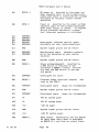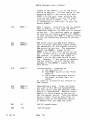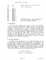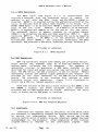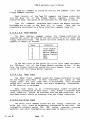
1
PDO-3 Hardware User's Manual
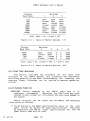
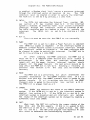
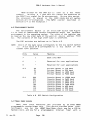
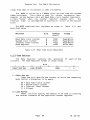
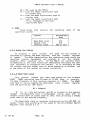
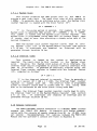
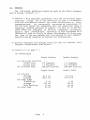
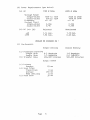
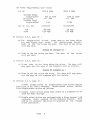
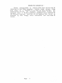
6. 10.0 USART Registers
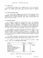
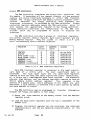
The USART provides five a-bit interface registers.
Communication with the USART registers may be carried on in either the
word or byte mode.
Significant data always occupies, the low order
byte, and the value of the high order byte is undefined.
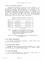
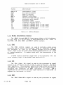
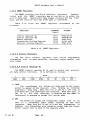
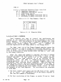
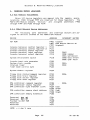
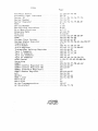
Table
proc essor.
6.10
lists
the
USART
registers
ADDRESS
(Word)
REGISTER
accessable
by
the
ACCESS
------------------------------------~----------------
Control Register #1
Control Register #2
Status Register
Transmitter Holding Register
Receiver Holding Register
FCI0
FCll
FC12
FC13
FC13
Read/write
Read/Write
Read only
Write only
Read only
-~-----------------~---------------------------------
Table 6. 10
USART Registers
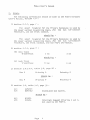
6. 10. O. 0 Contro 1 Reg i s ters
The two 8-bit Control registers hold device programming
information such as mode selection, interface signal control, and
data format.
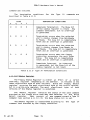
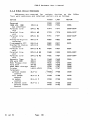
6.10.0.0.0 Control Register #1
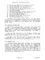
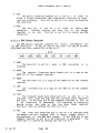
The USART Control register #1 is used to define line
and data control functions.
It is defined as follows:
protocol
BITS
----7-------6-------5-~-----4-------3------2------1-------0----
! LOOP
BRK
MISe!
ECHO!
PE
RE
RTS
DTR
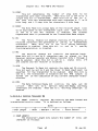
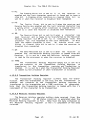
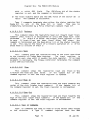
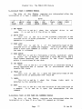
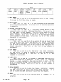
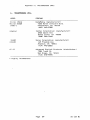
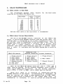
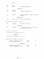
1) LOOP:
The Loop/Normal bit allows all data sent to the transmitter to appear at the receiver..
thus forming an internal
diagnostic data loop.
When this bit is set to 1,. the loop is
activated and ring interrupts are disabled.
When this bit is
set to 0,
the ring interrupt is enabled 'and the USART is
configured to operate in normal full duplex mode.
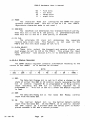
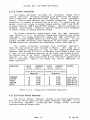
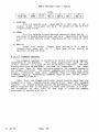
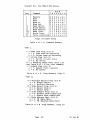
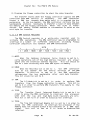
2) BRK:
The Break bit allows the transmitter output line to be
held in a continuous space state starting at the next
character.
When this bit is set to 0 and the transmitter is
enabled,
the transmitter acts normally except that the transmitter output line is heI~ in the spacing state.
31
Jan 81
Page
62.