1
LDS II
PROGRAMMING
GUIDE
PART NUMBER 880019-0123
Revised: September 5, 2006 CPC
© Copyright 2006 by Microcom Corporation, Lewis Center, Ohio – All rights reserved.
Printed in the United States of America
This Page Intentionally Left Blank
This Page Intentionally Left Blank
Proprietary Statement
This manual contains information proprietary to Microcom Corporation. This information is
intended solely for the use of parties operating and maintaining such equipment described
herein.
Product Enhancements
Microcom Corporation is committed to the continual improvement of performance and
quality in our products. For this reason, specifications are subject to change without notice.
Liability Disclaimer
Microcom Corporation makes every effort to assure that all information and specifications
contained in this manual are accurate; however, mistakes are sometimes made. Microcom
Corporation shall not be liable for any damages resulting in the use or misuse of this
product. The exclusion or limitation involving consequential or incidental damage does not
apply to all states; therefore limitation mentioned above may or may not apply.
FCC Compliance Statement
This equipment has been tested and found to comply with the limits for a Class A digital
device, pursuant to Part 15 of the FCC rules. These limits are designed to provide
reasonable protection against harmful interference when the equipment is operated in a
commercial environment. This equipment generates, uses, and can radiate radio frequency
energy, and if not installed and used in accordance with the instructions contained in this
manual, may cause harmful interference to radio communications.
SolarWinds® is a registered trademark of SolarWinds.Net, Inc.
Tera Term Pro® is a registered trademark of T. Teranishi.
HyperTerminal® and HyperAccess® are trademarks of Hilgraeve Inc.
Centronics® is a registered trademark of Data Computer Corporation.
Procomm Plus® is a registered trademark of Intuitive Communications.
Arial® is a registered trademark of The Monotype Corporation.
TrueType® is a registered trademark of Apple Computer, Inc.
Microsoft®, Windows 95®, Windows 98®, Windows 2000®, Windows NT®, Windows Notepad® are registered trademarks of
Microsoft Corporation.
IBM® products and name are registered trademarks of International Business Machines Corporation.
Other products and company names mentioned herein may be trademarks of their respective owners.
Table of Contents
INTRODUCTION............................................................................................................. 1
CHAPTER 1: DESIGNING USING LDSII ....................................................................... 3
1.1
SPECIAL CONTROL CODES ..................................................................................... 3
1.2
SCRIPT CREATION: AN OVERVIEW ........................................................................... 5
1.3
BEGIN SCRIPT - ^A)FILENAME ................................................................................. 6
1.4
SCRIPT HEADER .................................................................................................... 6
1.4.1
LSX (Label Width) ....................................................................................... 7
1.4.2
LSY (Label Height) ...................................................................................... 7
1.4.3
GAP (Gap Size)........................................................................................... 7
1.4.4
DRM (Distance to Registration Mark) .......................................................... 8
1.4.5
SPD (Print Speed) ....................................................................................... 8
1.4.6
DET (Detection Method) .............................................................................. 8
1.4.7
OFX (Offset X Direction).............................................................................. 9
1.4.8
OFY (Offset Y Direction).............................................................................. 9
1.5
FORMAT ENTRY COMMAND - ^FN) ........................................................................... 9
1.5.1
XB (X Coordinate) ..................................................................................... 10
1.5.2
YB (Y Coordinate) ..................................................................................... 10
1.5.3
CI (Conversion Identifier).......................................................................... 10
1.5.4
SW (Size Width) ......................................................................................... 13
1.5.5
SH (Size Height)........................................................................................ 13
1.5.6
AI (Attribute Index)..................................................................................... 14
1.5.7
DN (Direction)............................................................................................. 15
1.5.8
FO (Field Orientation)................................................................................ 15
1.5.9
FJ (Field Justification)................................................................................. 15
1.5.10 FW (Field Width)........................................................................................ 16
1.5.11 CS (Character Spacing) ............................................................................. 16
1.5.12
FC (First Character)................................................................................... 17
1.5.13 CC (Character Count)................................................................................. 17
1.6
TEXT ENTRY COMMAND - ^TN).............................................................................. 17
CHAPTER 2: PRINTER COMMANDS.......................................................................... 19
2.1
SCRIPT MANAGEMENT COMMANDS ........................................................................ 19
LDSII Programming Guide - 880015-0123
i
2.1.1
Begin Script - ^A)filename...........................................................................20
2.1.2
Begin Temporary Script - ^AT)filename ......................................................20
2.1.3
Format Entry Command - ^Fn)XB,YB,CI,SW,SH,AI,DN,FO,FJ,FW,CS,FC,CC .......20
2.1.4
Text Entry Command - ^Tn)text data ..........................................................20
2.2
2XX SERIES COMMANDS .......................................................................................21
2.2.1
^D200) LSX, LSY, GAP, DRM, SPD, DET, OFX, OFY (Script Header)......21
2.2.2
^D202)n (Text Replacement Header) .......................................................21
2.3
3XX SERIES COMMANDS .......................................................................................22
2.3.1
^D300)n (Print Command) ........................................................................23
2.3.2
^D305)1 (Infinity Print Command).............................................................23
2.3.3
^D311)1 (Top-OF-Form) ...........................................................................23
2.3.4
^D312)n (Form Feed) ...............................................................................23
2.3.5
^D313)n1,n2 (Advance Media) ..................................................................23
2.3.6
^D315)n (Calibrate Sensor Thresholds)....................................................23
2.3.7
^D323)n
2.3.8
^D324)n (List Statistics) ............................................................................24
2.3.9
^D325)n (List Selections)..........................................................................24
(List Enablements).....................................................................24
2.3.10 ^D326)n
(List Settings)............................................................................24
2.3.11 ^D327)1 (List Status) ................................................................................24
2.3.12 ^D340)filename (Load/Save File)...............................................................25
2.3.13 ^D341)type
(List Catalog) ........................................................................25
2.3.14 ^D342)filename (Delete File) .....................................................................25
2.3.15 ^D343)filename (List Script).......................................................................26
2.3.16 ^D345)filename (Load Volatile File) ...........................................................26
2.3.17 ^D346)1 (Defragment Flash Files) ............................................................26
2.3.18 ^D350)filename (Execute Script) ...............................................................27
2.3.19 ^D360)1 (List Memory Available) ..............................................................27
2.3.20 ^D365)?
(List Status Response List)........................................................27
2.3.21 ^D390)1 (Reset Printer) ............................................................................29
2.3.22 ^D391)1 (Restore Configuration Defaults) ................................................29
2.3.23 ^D392)1 (Restore Property Defaults)........................................................29
2.3.24 ^D394)1 (Draw Platen Roller Compensation Line) ...................................30
2.4
5XX SERIES COMMANDS .......................................................................................30
2.4.1
ii
^D501)n (Select Emulation Mode) ............................................................30
LDSII Programming Guide - 880015-0123
2.4.2
^D506)n (Select Cutter Type) ................................................................... 30
2.4.3
^D507)n (Select Printed Media Handler) .................................................. 31
2.4.4
^D508)n (Select Label Present Detector Type) ........................................ 31
2.4.5
^D509)n (Select INPUT1 Response Polarity and Action) ......................... 31
2.4.6
^D541)n (Select Button 1 Response) ....................................................... 32
2.4.7
^D550)n (Select Printer Response Set).................................................... 32
2.4.8
^D564)n (Select Measurement Units)....................................................... 33
2.4.9
^D565)n (Select Speed Units) .................................................................. 33
2.4.10 ^D566)n (Select Temperature Units) ........................................................ 34
2.4.11 ^D567)filename (Select Power-up Script)................................................. 34
2.4.12 ^D570)n (Select Active Port) .................................................................... 34
2.4.13 ^D581)n (Select Stock Out Handling Method) .......................................... 34
2.4.14 ^D597)n (Select Dispense Mode) ............................................................. 35
2.5
6XX SERIES COMMANDS ....................................................................................... 36
2.5.1
^D631)n (Set Media Width) ...................................................................... 36
2.5.2
^D632)n (Set Media Height) ..................................................................... 36
2.5.3
^D633)n (Set GAP Size)........................................................................... 36
2.5.4
^D634)n (Distance To Registration Mark)................................................. 36
2.5.5
^D635)n (Set Print Speed)........................................................................ 37
2.5.6
^D636)n (Set Detection Mode) ................................................................ 37
2.5.7
^D637)n (Offset X Direction)..................................................................... 39
2.5.8
^D638)n (Offset Y Direction)..................................................................... 39
2.5.9
^D639)n (Set Centering Offset) ................................................................ 39
2.5.10 ^D640)n (Set Delay Time Between Labels).............................................. 39
2.5.11 ^D641)n (Set Retraction Delay Time) ....................................................... 39
2.5.12 ^D642)n (Set Advance/Retract Distance) ................................................. 40
2.5.13 ^D643)n
(Set Print Head to LPD Distance).............................................. 40
2.5.14 ^D644)n
(Set Idle Recognition Delay)...................................................... 40
2.5.15 ^D645)n1
(Set Advance/Retract Speed).................................................. 40
2.5.16 ^D646)n
(Set Platen Roller Compensation)............................................. 40
2.5.17 ^D647)dc,dp (Set Print Head Parameters) ............................................... 41
2.5.18 ^D648)n (Set Blackline Sensor to Print Head Distance) ........................... 41
2.5.19 ^D649)n (Set Gap Sensor to Print Head Distance)................................... 42
2.5.20 ^D655)n (Set Labels Printed) ................................................................... 42
LDSII Programming Guide - 880015-0123
iii
2.5.21 ^D670)
(Set Serial Port) ..........................................................................42
2.5.22 ^D674)n (Set Ethernet Port Number)........................................................43
2.5.23 ^D675)n (Set Printer IP Address)..............................................................43
2.5.24 ^D676)n (Set Server/Host IP Address) .....................................................43
2.5.25 ^D677)n (Set Gateway IP Address) ..........................................................43
2.5.26 ^D678)n (Set Broadcast Mask Address) ...................................................44
2.5.27 ^D679)n (Set Net Mask Address) .............................................................44
2.5.28 ^D680)n (Set Gap Threshold) ...................................................................44
2.5.29 ^D681)n (Set Blackline Threshold) ...........................................................44
2.5.30 ^D682)n (Set Stock Sensor Threshold) ....................................................44
2.5.31 ^D683)n (Set LPD PWM)..........................................................................44
2.5.32 ^D690)n (Set Darkness Range) ................................................................45
2.6
7XX SERIES COMMANDS .......................................................................................45
2.6.1
^D701)n (Enable Force LDS1 on Power-up).............................................45
2.6.2
^D720)n (Enable Auto Power-Up Script) ..................................................45
2.6.3
^D721)n (Enable Auto Enquiry After Print)................................................45
2.6.4
^D723)n (Enable Auto TOF on Power up) ................................................45
2.6.5
^D726)n (Enable Auto ACK/NAK).............................................................46
2.6.6
^D727)n (Enable Auto Error Reporting) ....................................................46
2.6.7
^D735)n (Enable Immediate Graphic Printing)..........................................46
2.6.8
^D736)n (Enable Immediate Graphic Centering) ......................................46
2.6.9
^D740)n (Enable Cutter) ...........................................................................47
2.6.10 ^D741)n (Enable PMH) .............................................................................47
2.6.11 ^D760)n (Enable Auto Defrag on Power-up).............................................47
2.6.12 ^D770)n (Enable Software Flow Control)..................................................47
2.6.13 ^D771)n (Enable Hardware Flow Control) ................................................47
2.7
iv
9XX SERIES COMMANDS .......................................................................................48
2.7.1
^D900)d, s (Diagnostic Tic-Tic Mode).......................................................48
2.7.3
^D930)level (Get Access Code Key).........................................................53
2.7.4
^D931)level, password (Change Access Level).........................................53
2.7.5
^D932)
2.7.6
^D945)n (List Diagnostic Dump) ...............................................................53
2.7.7
^D960)n (Print Test Pattern) .....................................................................54
2.7.8
^D971)n (Edit Inches Printed Statistic) .....................................................54
(List Access Passwords) .............................................................53
LDSII Programming Guide - 880015-0123
2.7.9
^D972)n (Edit Total Inches Run Statistic) ................................................. 54
2.7.10 ^D973)n (Edit Power on Time Statistic) .................................................... 54
2.7.11 ^D974)n (Edit Head Up Cycles Statistic) .................................................. 54
2.7.12 ^D975)n (Clear All Statistics) .................................................................... 55
2.7.13 ^D976)n (Edit Unit Serial Number) ........................................................... 55
2.7.14 ^D977)n (Edit Cutter Cycles Statistic)....................................................... 55
2.7.15 ^D978)0xn (Edit Ethernet MAC Address) ................................................. 55
2.7.16 ^D979)n (Edit CPU Serial Number) .......................................................... 55
2.7.17 ^D980)n (Calibrate Sensors) .................................................................... 55
CHAPTER 3: UPDATING FLASH MEMORY ............................................................... 57
3.1
COMPRESSED FILE UPDATE .................................................................................. 57
3.2
MCA COMPRESSED FILE RECOVERY..................................................................... 58
CHAPTER 4: SPECIAL FEATURES ............................................................................ 61
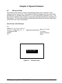
4.1
REVERSE VIDEO .................................................................................................. 61
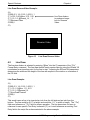
4.2
LINE DRAW .......................................................................................................... 62
CHAPTER 5: BAR CODES .......................................................................................... 65
5.1
GENERATING BAR CODES..................................................................................... 65
5.1.1
CI Parameter .............................................................................................. 65
5.1.2
SW Parameter ............................................................................................ 65
5.1.3
SH Parameter............................................................................................. 65
5.1.4
AI Parameter .............................................................................................. 65
5.2
LINEAR BAR CODES ............................................................................................. 66
5.2.1
Codabar (Rationalized)............................................................................... 66
5.2.2
Code 128 (Manual Compression)............................................................... 66
5.2.3
Code 128 (Automatic Compression)........................................................... 67
5.2.4
Code 39 ...................................................................................................... 68
5.2.5
Code 93 ...................................................................................................... 68
5.2.6
Code I2of5 (Interleaved 2 of 5)................................................................... 68
5.2.7
MSI0 (Modified Plessey)............................................................................. 68
5.2.8
MSI1 (Modified Plessey)............................................................................. 68
5.2.9
MSI2 (Modified Plessey)............................................................................. 69
5.2.10 Postnet ....................................................................................................... 69
5.3
2D BAR CODES ................................................................................................... 69
LDSII Programming Guide - 880015-0123
v
5.3.1
Data Matrix .................................................................................................69
5.3.2
PDF-417 .....................................................................................................74
CHAPTER 6: DIAGNOSTICS AND TROUBLESHOOTING ........................................77
6.1
DIAGNOSTIC MODE...............................................................................................77
6.1.1
Entering Diagnostic Mode...........................................................................77
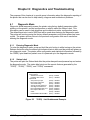
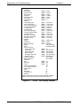
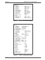
6.1.2
Status Label................................................................................................77
6.2
ENQUIRY RESPONSES ..........................................................................................80
6.3
FATAL ERROR RESPONSES ...................................................................................83
6.3.1
>STOCK OUT< (01) ...................................................................................83
6.3.2
>STOCK OVERADVANCED< (02) .............................................................84
6.3.3
>STOCK JAMMED< (03)............................................................................84
6.3.4
>INCORRECT STOCK< (04)......................................................................84
6.3.5
>CUTTER JAMMED< (10)..........................................................................84
6.3.6
>CUTTER INOPERATIVE< (11).................................................................84
6.3.7
>CUTTER WATCHDOG STOPPED CUTTER< (12) ..................................85
6.3.8
>CUTTER WATCHDOG WON”T RESET< (13) .........................................85
6.3.9
>MISSING LABEL< (1C) ............................................................................85
6.3.10 >INCOMPLETE FORM< (1D) .....................................................................85
6.3.11 >CATCH TRAY FULL< (20)........................................................................85
6.3.12 >SCRIPT ERROR< (30) .............................................................................85
6.3.13 >INVALID PARAMETER< (31) ...................................................................85
6.3.14 >PARSER ERROR< (32)............................................................................86
6.3.15 >COMM ERROR< (40) ...............................................................................86
6.3.16 >FLASH ERROR< (51)...............................................................................86
6.4
vi
BASIC STATUS RESPONSES ..................................................................................86
6.4.1
>OK< (06) ...................................................................................................86
6.4.2
>INPUT 1< (21) ..........................................................................................87
6.4.3
>INPUT 2< (22) ..........................................................................................87
6.4.4
>RESTARTED< (80)...................................................................................87
6.4.5
>READY< (81) ............................................................................................87
6.4.6
>BUSY< (82) ..............................................................................................87
6.4.7
>PAUSED< (83) .........................................................................................87
6.4.8
>PRINTING< (84) .......................................................................................87
LDSII Programming Guide - 880015-0123
6.4.9
>FEEDING< (85) ........................................................................................ 88
6.4.10 >LABEL/TAG PRESENT< (86)................................................................... 88
6.4.11 >STOCK ADVANCED< (87)....................................................................... 88
6.4.12 >FLASH DEFRAGMENTING< (8A)............................................................ 88
6.3.13 >STOCK NOT LOADED< (8F) ................................................................... 88
6.4.14 >RETRACTION DELAY< (90) .................................................................... 88
6.4.15 >PRINT DELAY< (91) ................................................................................ 88
6.4.16 >FLASH MEMORY LOW< (B0).................................................................. 89
6.4.17 >BUTTON 1 TAPPED< (C0) ...................................................................... 89
6.4.18 >BUTTON 1 HELD< (C1) ........................................................................... 89
6.4.19 >TEMPERATURE OUT OF RANGE< (D0) ................................................ 89
6.4.20 >NONEXISTENT COMMAND< (D1) .......................................................... 89
6.4.21 >INCOMPLETE COMMAND< (D2) ............................................................ 89
6.4.22 >ZIP FILE ERROR< (D3) ........................................................................... 89
6.4.23 >FILE CONVERSION ERROR< (D4) ......................................................... 90
6.4.24 >UNSUPPORTED FILE TYPE< (D5) ......................................................... 90
6.4.25 >FILE NOT FOUND< (D6).......................................................................... 90
6.4.26 >INADEQUATE ACCESS MODE< (D7)..................................................... 90
6.4.27 >FILE IS READ ONLY< (D9)...................................................................... 90
6.4.28 >INADEQUATE FLASH SPACE< (DA) ...................................................... 90
6.4.29 >I/O FAILURE< (DB) .................................................................................. 90
6.4.30 >FONT/GRAPHIC NOT FOUND< (DC) ..................................................... 91
6.3.31 >SWITCH 0 ACTUATED< (E1) .................................................................. 91
6.3.32 >SWITCH 1 ACTUATED< (E2) .................................................................. 91
6.3.33 >SWITCH 2 ACTUATED< (E3) .................................................................. 91
6.3.34 >TOF SWITCH ACTUATED< (E4) ............................................................. 91
6.4.35 >FIELD OFF IMAGE< (F0) ......................................................................... 91
6.3.36 >GRAPHIC TOO LARGE< (F2).................................................................. 91
6.4.37 >POWERED DOWN< (FF)......................................................................... 91
CHAPTER 7:
7.1
RS-232 SERIAL ................................................................................................... 93
7.1.1
7.2
COMMUNICATIONS............................................................................ 93
RS-232 Printer Cables................................................................................ 93
ETHERNET - 10/100 BASE-T ............................................................................... 94
LDSII Programming Guide - 880015-0123
vii
7.3
USB PORT ..........................................................................................................94
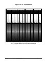
APPENDIX A – ASCII CHART......................................................................................95
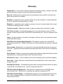
GLOSSARY ..................................................................................................................97
INDEX..........................................................................................................................101
USER NOTES .............................................................................................................103
viii
LDSII Programming Guide - 880015-0123
List of Tables
Table 1
Resident Bitmapped Fonts ................................................................................ 11
Table 2
Bar Code Index ................................................................................................. 12
Table 3
Attribute Index ................................................................................................... 14
Table 4
Field Justifications ............................................................................................. 16
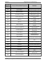
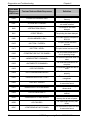
Table 5
^Dxxx Series Commands .................................................................................. 19
Table 6
^D365) Status Response List ............................................................................ 29
Table 7
Print Head Parameters ...................................................................................... 41
Table 8
Blackline Sensor to Print Head Distance........................................................... 42
Table 9
Gap Sensor to Print Head Distance................................................................... 42
Table 10
^D670) Parameters ........................................................................................... 43
Table 11
^D900) and ^D902) Parameters ........................................................................ 48
Table 12
Access Levels ................................................................................................... 53
Table 13
Code 128 Special Function Access ................................................................... 66
Table 14
Data Matrix Configuration Parameters .............................................................. 71
Table 15
Data Matrix Encoding Schemes ........................................................................ 71
Table 16
ASCII Codeword Values.................................................................................... 72
Table 17
Data Matrix Special Characters......................................................................... 74
Table 18
PDF-417 Error Correction Level ........................................................................ 75
Table 19
Enquiry Responses ........................................................................................... 83
Table 20
RS-232 Cable Configurations............................................................................ 93
LDSII Programming Guide - 880015-0123
ix
x
LDSII Programming Guide - 880015-0123
List of Figures
Figure 1
Sample Script Format.......................................................................................... 6
Figure 2
Script Parameters................................................................................................ 7
Figure 3
Distance-to-Registration Mark (DRM).................................................................. 8
Figure 4
Format Entry Command ...................................................................................... 9
Figure 5
Text Entry Command......................................................................................... 18
Figure 6
Detection Mode - None...................................................................................... 37
Figure 7
Detection Mode - Blackline................................................................................ 38
Figure 8
Detection Mode - Die-cut and Blowhole ............................................................ 39
Figure 9
^D900 Blackline Listing ..................................................................................... 49
Figure 10
^D900 Blackline Threshold Example .............................................................. 50
Figure 11
^D900 Die-cut Listing...................................................................................... 51
Figure 12
^D900 Die-cut Threshold Example ................................................................. 52
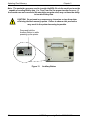
Figure 13
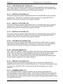
Auxiliary Button............................................................................................... 60
Figure 14
Reverse Video ................................................................................................ 61
Figure 15
Line Draw Reverse Video............................................................................... 62
Figure 16
Line Draw Feature .......................................................................................... 63
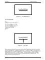
Figure 17
Two Lines ....................................................................................................... 63
Figure 18
Box Creation................................................................................................... 64
Figure 19
Code 128 Subset Switching ........................................................................... 67
Figure 20
Data Matrix Format Structure ......................................................................... 69
Figure 21
PDF-417 Format Structure ............................................................................. 74
Figure 22
^D323) - List Enablements Example .............................................................. 77
Figure 23
^D326) - List Settings Example ...................................................................... 78
Figure 24
^D325) - List Selections Example................................................................... 79
LDSII Programming Guide - 880015-0123
xi
Figure 25
^D324) - List Statistics Example ..................................................................... 79
Figure 26
^D960)1 or ^K Test Pattern............................................................................. 80
Figure 27
10/100 BASE-T Ethernet Port......................................................................... 94
xii
LDSII Programming Guide - 880015-0123
Introduction
This programming guide provides the user with an overview of the LDSII command structure
and label formatting requirements.
The Label Design Software (LDSII) is the resident printer control language that is used to
create, store and print label scripts, while also controlling the other various printer features.
LDSII can be used in conjunction with mini-computers, mainframes, personal computers,
and most other special purpose computers. The examples provided within this guide use
an IBM® compatible personal computer with an available serial port, and a terminal
emulation software program (i.e., Procomm Plus, HyperTerminal, HyperAccess or Tera
Term Pro). Microcom Corporation printers are shipped with serial parameters set to 9600baud, no parity, 8 data bits, and 1 stop bit unless setup with a custom configuration. The
emulator program will have to be set to these parameters for proper serial communication.
LDSII printers require the use of hardware flow control (CTS/RTS) for proper data
management to occur.
During the power-up, the indicator light will flash amber and green, the printer copies the
current application (source code or firmware) to the RAM memory. This allows for faster
transfer and operation after the printer has been powered-up. The second phase of the
power up is the printer’s initialization process and flash file system restore. This process
restores all of the files saved in the flash memory. The power-up process will vary in time
depending on the files that have been saved into the printer’s flash memory
LDSII Programming Guide - 880015-0123
1
2
LDSII Programming Guide - 880015-0123
Chapter 1: Designing Using LDSII
Label formats or scripts are very easy to design using LDSII by following these basic steps
below. LDSII printers require the use of hardware flow control (CTS/RTS) for proper data
management to occur. Software flow control should not be used to manage data being sent
to an LDSII printer.
1. Determine the media type, media size, and print speed desired for your application;
enter this data into the script header.
2. Determine the type of handling operation desired and use the appropriate LDSII
printer control commands.
3. Define the formatting instructions for the type and placement of data.
4. Enter the text data that corresponds to the formatting instructions.
5. Send the script to the printer.
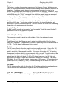
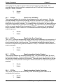
1.1
Special Control Codes
The printer can accept either the one-character control code (“Ctrl + E”) or the two-character
caret (^) plus alpha character (“^E”). Control codes are processed immediately while the
^Dxx commands are processed in the order they are issued. It is recognized that some
mainframe and mini-computers cannot use the ASCII carat “^” character. The ASCII pipe
symbol “|” can be used as a substitute for these instances. Below is a list of special control
codes used by LDSII. A one (1) second delay should follow all control codes before
executing the next command to assure that the code and/or command executed correctly.
^A
Begin Script: Marks the beginning of an LDSII script file entry.
^C
Clear Halting Error: When issued five consecutive times with a one second delay
between each ^C the printer will clear blocking or halting error conditions returning
^Dxx command responsiveness. If the printer has remaining jobs in the queue, the
printer will return to a >PAUSED< state instead of the >READY< state. Please note
that if the condition that caused the error still exists, pressing the print button and/or
sending further scripts will cause this error to be reported again. Halting error
messages are conditions that must be corrected before printing may resume. Refer
to section 6.3 for additional information regarding error conditions.
^D
Standard Command Preface: Combined with three-digit number issues a
command. See Chapter 2 for more information regarding ^D commands.
^E
Printer Enquiry: Causes the printer to list its current status to an active
communications port.
^H
Back Space: Causes the printer to issue a back space.
LDSII Programming Guide - 880015-0123
3
Designing Using LDSII
Chapter 1
^J
Line Feed: Represents a Line Feed (LF) character or 0x0A.
^K
Print Test Label: Causes the printer to print a test pattern consisting of diagonal
lines used to test the condition of the dots on the print head.
^L
Form Feed: Scrolls one label out of the printer using the previous formats layout.
^M
Carriage Return: Represents a Carriage Return (CR) character or 0x0D.
^O
Top-of-Form (TOF): Instructs the printer to perform a TOF operation which uses the
Label Present Detector (LPD) in order to retract the media to the proper alignment in
regards to the print head.
^P
Print: Causes the printer to print. Note: If no label scripts are loaded or stored in the
printer’s memory, the printer will not print a label until a script is processed.
^Q
Send Data: Instructs the printer to send data or resume sending data (XON).
^R
Reset Printer: Instructs the printer to perform a reset through software that
duplicates a hard reset. Issuing the ^R causes the reset to occur immediately,
bypassing commands sent but not yet processed. The ^D390)0 command is a
queued or serialized version of the ^R and should be used if a reset condition is
desired programmatically.
^S
Stop Sending Data: Instructs the printer to stop sending data (XOFF).
^U
List Selections: Causes the printer to list the current configured selections of the
printer through an active communications port.
^V
List Settings: Causes the printer to list the current configured settings of the printer
through an active communications port.
^W
List Statistics: Causes the printer to list the current statistics of the printer through
an active communications port.
^X
Toggle Pause: Pauses the printer if printing, resumes if the printer is currently
paused.
^Y
List Enablements: Causes the printer to list the current configured enablements of
the printer through an active communications port.
^Z
End Script: Marks the end of a script file.
^]
Cancel All Jobs: Causes all jobs currently queued to be deleted returning the printer
to its idle state. Refer to the ^D330 command.
4
LDSII Programming Guide - 880015-0123
Chapter 1
1.2
Designing Using LDSII
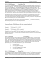
Script Creation: An Overview
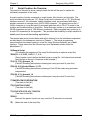
This section is intended to show a sample script file that will be used to explain the
individual components of the script.
A script consists of printer commands, a script header, field formats, and text data. The
script is initiated by sending an “^A)” (Begin Script) and continues until a “^Z)” (End Script)
has been received. All commands, unless otherwise noted, are terminated with either
another command or carriage return (ASCII 0x0D) character. The printer ignores the LF
(0x0A) character so it may be helpful to terminate each line with a CR+LF to assist in the
creation and troubleshooting of script files. Script files may contain up to a maximum total of
20,000 characters and up to 1000 different commands. Each command may contain up to
a total of 20 characters for the argument. This provides the flexibility in script creation to
handle even the most demanding applications.
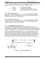
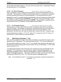
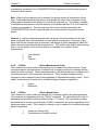
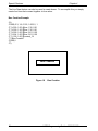
The sample label script is listed below and will be referred to as the individual components
are discussed in the subsequent sections of Chapter 1. The actual programming
instructions that have been typed into a text file, using Windows Notepad, are in bold
typeface. These instructions are followed by a brief explanation shown within the
parentheses “()”.
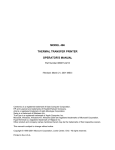
^A)Sample Script
(^A indicates the beginning of the script file followed by an optional script title)
^D200)3.3, 1.9, 0.125, 1.063, 5 , 1 , 0, 0
(Script header used to define the label format or script file. Units have been entered
using inches as the unit of measure in this example.)
^F1)0.15, 1.50, @normal_14
(Field #1 formatting instructions containing text using a normal 14 point font)
^F2)0.30, 0.50,@code128auto, 3, 0.70
(Field #2 formatting instructions containing a Code128 bar code using automatic
compression)
^F3)0.60, 0.13, @normal_10
(Field #3 formatting instructions containing text using a normal 10 point font)
^T1)MICROCOM CORPORATION
(Text data for field #1)
^T2)12345678901234567
(Text data for field #2)
^T3)12345 678 90123 45 6 7 8901234
(Text data for field #3)
^D300)1
(Instructs the printer to print one copy once the ^Z instruction is received)
^Z)
(Marks the end of the script file)
LDSII Programming Guide - 880015-0123
5
Designing Using LDSII
Chapter 1
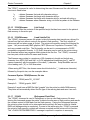
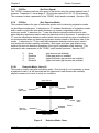
Field #1 –
The ^F1) and ^T1) commands
are formatting this field.
MICROCOM CORPORATION
Field #3 –
The ^F3) and
^T3) commands
are used to
format this field.
Field #2 –
The ^F2) and
^T2) commands
are used to
format this bar
code.
12345 678 90123 45 6 7 8901234
Figure 1
1.3
Sample Script Format
Begin Script - ^A)filename
This command is used to mark the beginning of a script file. The script may be saved into
the printer’s non-volatile flash memory if a title or filename is placed after the command.
The filename may contain to a maximum of 20 characters in length and include any
character from ASCII 0x20 and 0x41 to 0x7A (alphabetical characters plus [\]_’and SP
(space character)) with the exception of the caret (^) character. Script filenames can not
use a leading zero (“0”) or 0x30 characters. A script that contains a “filename” will only save
the script and will not process and print. The “^D350)filename” would be issued to recall
and process the saved script. If the script does not contain a “filename”, the script is
processed normally and will be volatile in nature.
For Example: The previous example script’s first line is “^A)Sample Script” which would
save this script into the printer’s flash memory (non-volatile) as “Sample Script”.
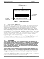
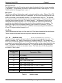
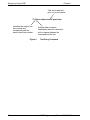
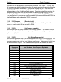
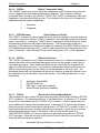
1.4
Script Header
The script header consists of the “^D200)” command followed by eight parameters that
control the media layout as well as printer operation. The parameters must be separated by
a delimiter, comma by default, and are entered using the current unit of measure selected
by the “^D564)” command. The origin or the starting coordinate is always the lower left
corner as the media exits the printer. This command may be issued from outside a script
but is typically created within a script file.
The script header is used to temporarily override the individual header parameters when
issued from within a script file. The parameters may be defaulted to the current persistent
value by not entering a value between the delimiters. Each of the header parameters has
an “^D6xx)” command equivalent that when set outside a script file remains persistent.
For Example: “^D200)LSX,LSY,,DRM”, would cause the “GAP” parameter to be defaulted
to the current “^D633)” value that was set outside a script file.
6
LDSII Programming Guide - 880015-0123
Chapter 1
Designing Using LDSII
The persistent commands are helpful in setting the printer up for a basic configuration and
then override them within the script. It is recommended that a script header contain values
for each and every parameter if access to the persistent command listings is not available.
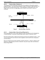
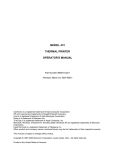
^D200)LSX, LSY, GAP, DRM, SPD, DET, OFX, OFY
Print Direction
MICROCOM CORPORATION
LSY – Y Direction
(Virtually unlimited)
12345 678 90123 45 6 7 8901234
This
is the
origin
LSX – X Direction
(Print head limitation)
Figure 2
Script Parameters
1.4.1 LSX (Label Width)
LSX, LSY, GAP, DRM, SPD, DET, OFX, OFY
Specifies the width or “X” direction of the label in the unit of measure selected by the
“^D564)” command. The maximum LSX is the width of the print head installed in the printer.
This parameter is always required for proper script operation. See also ^D631)n command.
1.4.2 LSY (Label Height)
LSX, LSY, GAP, DRM, SPD, DET, OFX, OFY
Specifies the height or “Y” direction of the label in the unit of measure selected by the
“^D564)” command. The maximum LSY height is 24”. This parameter is always required
for proper script operation. See also ^D632)n command.
1.4.3 GAP (Gap Size)
LSX, LSY, GAP, DRM, SPD, DET, OFX, OFY
The GAP is the height of the registration mark on each label and/or tag. This would be the
backing material found between die-cut labels, blowhole sense mark, and/or the blackline
height. The value is entered using the current unit of measure selected by the “^D564)”
command. See also ^D633)n command.
LDSII Programming Guide - 880015-0123
7
Designing Using LDSII
Chapter 1
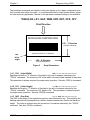
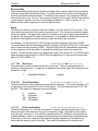
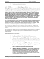
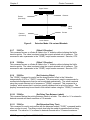
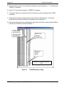
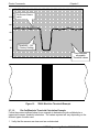
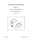
1.4.4 DRM (Distance to Registration Mark)
LSX, LSY, GAP, DRM, SPD, DET, OFX, OFY
This parameter is typically only used when the registration mark is not located at the edge of
the media. The “DRM” is the distance from the leading edge of the media to the beginning
of the registration mark. The DRM is entered using the current selected unit of measure
selected by the “^D564)” command. See also ^D634)n command.
Print Direction
DRM, (0.72”)
Media height (LSY)
Media that contains
an offset registration
mark.
The perforation
indicates the
separation of
individual tags.
Figure 3
Registration
Mark
(Black line)
Distance-to-Registration Mark (DRM)
LSX, LSY, GAP, DRM, SPD, DET, OFX, OFY
1.4.5 SPD (Print Speed)
This is the speed of the printer while printing, which is defined in either “inches/second (ips)”
or “centimeters/second (cms) as selected by the “^D564)” command. The print speed can
be adjusted anywhere from 1 ips (2.54 cms) to 6 ips (15.24 cms). See also ^D635)n
command.
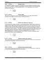
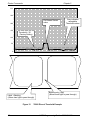
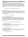
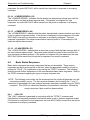
1.4.6 DET (Detection Method)
LSX, LSY, GAP, DRM, SPD, DET, OFX, OFY
This parameter selects the type of method the printer uses for detecting registration marks
on different media types. A selection of a “0” disables registration detection and is used in
conjunction with media that does not contain a registration mark like continuous media. The
detectors are only used to detect Stock Out conditions when a selection of “0” is selected. A
selection of a “1” uses the reflective detection method and is used when detecting
registration marks located on the bottom side of the media. A selection of a “2” uses the
transmissive detection method which requires both the upper and the lower gap detectors to
be installed on the printer. This method can be used with any type of media but is not
recommended when only detecting registration marks located on the bottom side of the
media. A selection of a “3” also uses the transmissive detection method and is used in
8
LDSII Programming Guide - 880015-0123
Chapter 1
Designing Using LDSII
conjunction with media containing a blowhole. The blowhole and die-cut selections differ on
how they detect an out of stock condition. See also ^D636)n command.
0
1
2
3
None
Blackline
Die-cut
Blowhole
(gap sensors are disabled)
(lower gap sensor is enabled)
(upper and lower gap sensors are enabled)
(upper and lower gap sensors are enabled)
LSX, LSY, GAP, DRM, SPD, DET, OFX, OFY
1.4.7 OFX (Offset X Direction)
This parameter moves or offsets all fields in the “X” direction without altering the field’s
insertion points. The value is entered using the current unit of measure selected by the
“^D564)” command. See also ^D637)n command.
LSX, LSY, GAP, DRM, SPD, DET, OFX, OFY
1.4.8 OFY (Offset Y Direction)
This parameter moves or offsets all fields in the “Y” direction without altering the field’s
insertion points. The value is entered using the current unit of measure selected by the
“^D564)” command. See also ^D638)n command.
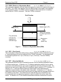
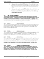
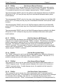
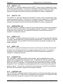
1.5
Format Entry Command - ^Fn)
The Format Entry command is used to define the characteristics, placement and
representation of the corresponding text data of the individual fields. This command starts
with the “^Fn)” structure which is then followed by thirteen different parameters that define
and control the desired field. The “n” is an identifier that represents the field number being
formatted and corresponds to the equivalent “^Tn)” line. As with the ^Dxxx commands,
multiple parameters must be separated by the comma (“,”) delimiter. The format entry
command can be issued from outside a script but is typically created within a script file.
Unlike the “^Dxx)” commands and the script header, the Format Entry Command typically
does contain default values as there are no equivalent commands for the individual
parameters. The default values are discussed under the individual parameter descriptions.
Field parameters
^Fn) XB, YB, CI, SW, SH, AI, DN, FO, FJ, FW, CS, FC, CC
The “n” identifies the field
number which always
starts at “1” and not “0”.
Figure 4
The comma delimiter
Format Entry Command
LDSII Programming Guide - 880015-0123
9
Designing Using LDSII
Chapter 1
1.5.1 XB
(X Coordinate)
XB, YB, CI, SW, SH, AI, DN, FO, FJ, FW, CS, FC, CC
This parameter is used to set the X coordinate of the field. The X coordinate is measured
from the left edge of the media, as viewed from the front of the printer. The value is entered
using the current unit of measure selected by the “^D564)” command and may contain any
number of digits desired. A leading zero before the decimal point is not required but should
be used to make trouble shooting scripts easier (i.e., .75 should be entered as 0.75). This
parameter does not contain a default value and is required.
XB, YB, CI, SW, SH, AI, DN, FO, FJ, FW, CS, FC, CC
1.5.2 YB
(Y Coordinate)
This parameter is used to set the Y coordinate of the field. The Y coordinate is measured
from the bottom edge of the media, as viewed from the front of the printer. The value is
entered using the current unit of measure selected by the “^D564)” command and may
contain any number of digits desired. A leading zero before the decimal point is not
required but should be used to make trouble shooting scripts easier (i.e., .75 should be
entered as 0.75). This parameter does not contain a default value and is required.
XB, YB, CI, SW, SH, AI, DN, FO, FJ, FW, CS, FC, CC
1.5.3 CI
(Conversion Identifier)
The Conversion Identifier (CI) determines how the associated text field will be rendered.
This parameter can be used to select from the available fonts, graphics, line draw feature,
and/or bar codes that will be used to render the associated Text Entry command line
(“^Tn)”). Objects that are stored in the printer’s flash memory are selected using the system
character (“@”) and the appropriate text identifier. This parameter can also be used to
select other user stored files by entering the name of the saved file into the CI parameter.
The entered values for the CI parameter are not case sensitive because the printer will
internally translate as lower case.
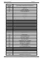
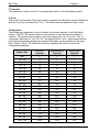
Resident Bitmapped Fonts
The resident fonts stored in the printer are listed in the table below. To access the resident
fonts, enter the appropriate Font Name into the CI parameter. The printer may store up to
nineteen bitmapped fonts and custom font sets are available upon request.
CI - Font Name
Font Sample
@normal_06
6 Point – 01234567890ABCDEFGHIJKLMNOPQRSTUVWXYZabcdefghijklmnopqrstuvwxwy
@bold_06
6 Point – 01234567890ABCDEFGHIJKLMNOPQRSTUVWXYZabcdefghijklmnopqrstuvwxwy
@normal_08
8 Point – 01234567890ABCDEFGHIJKLMNOPQRSTUVWXYZabcdefghijklmnopqrstuvwxwy
@bold_08
8 Point – 01234567890ABCDEFGHIJKLMNOPQRSTUVWXYZabcdefghijklmnopqrstuvwxwy
@normal_10
10 Point – 01234567890ABCDEFGHIJKLMNOPQRSTUVWXYZab
@bold_10
10 Point – 01234567890ABCDEFGHIJKLMNOPQRSTUVWXYZa
@normal_12
12 Point – 01234567890ABCDEFGHIJKLMNOPQRSTUVWXYZab
10
LDSII Programming Guide - 880015-0123
Chapter 1
Designing Using LDSII
CI - Font Name
Font Sample
@bold_12
12 Point – 01234567890ABCDEFGHIJKLMNOPQRSTUVWXYZa
@normal_14
14 Point – 01234567890ABCDEFGHIJKLMNOPQRSTU
@bold_14
14 Point – 01234567890ABCDEFGHIJKLMNOPQRST
@normal_16
16 Point – 01234567890ABCDEFGHIJKL
@bold_16
16 Point – 01234567890ABCDEFGHIJKL
@normal_20
@bold_20
@normal_24
@bold_24
20 Point – 01234567890ABCDEFGHIJ
20 Point – 01234567890ABCDEFGHI
24 Point – 0123456ABCDEGabc
24 Point – 012345ABCabcdefgh
@ocra_12
12 Point – 0123456789ABCDEFGHIJKLMNOPQRUSTUWXYZabc
@ocrb_08
8 Point – 1234567890ABCDEFGHIJKLMNOPQRSTUVWXZYabcdefghijklmnopqr
@ocrb_12
12 Point – 1234567890ABCDEFGHIJKLMNOPQRSTUV
Table 1
Resident Bitmapped Fonts
Font File Type Example:
If a normal 8 point font is desired then “@normal_08” should be entered for the CI
parameter in order for the proper font to be printed. Fonts are accessed by entering the
system character “@”, font name followed by the underscore character and then the point
size into the CI parameter.
Line Draw
The line draw feature is selected by entering “@line” into the CI parameter. The line draw
feature easily creates lines by using the XB and YB coordinates as an insertion point for the
line to start and then adjusting the SW and SH parameters to define the width and the
height of the line.
Line Draw Example:
^A)
^D200)3.3, 1.9, 0.125, 1.063, 5, 1
^F1)1.0, 1.0,@line, 1.11, 0.01
^F1)1.0, 1.0,@normal_14
^T1)Line Draw Feature
^D300)1
^Z)
LDSII Programming Guide - 880015-0123
11
Designing Using LDSII
Chapter 1
This script would cause a line to be inserted an inch from the left side and an inch from the
bottom. The line would be 1.11” in width or length (X direction) and would be 0.01” in height
(Y direction). The “^Fn)” field must reference a “^Tn)” field for proper operation. The line
draw does not have to reference its own specific Text Entry command (“^Tn)”) and may
reference an existing Text Entry field in the script file as demonstrated in the above
example. Refer to Chapter 4 for additional information regarding the line draw feature.
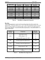
Bar Codes
The bar codes or symbologies are stored in the printer and can be selected by entering the
system character “@” followed by the text equivalent code of the desired symbology in the
CI parameter, refer to Table 2 for the available bar codes.
The bar codes that provide optional check digits can be accessed and printed by entering
“cs” immediately following the bar code text equivalent code. This is helpful to meet the
individual bar code specifications.
For example: If the user wanted to generate a human readable MSI1 that included the
check digits, “msi1cs_hr” would then be entered while “msi1_hr” would not include the check
digits in human readable form.
See Chapter 5 for more detailed information pertaining to bar codes and their individual
formatting requirements.
CI - Barcode Name
Bar code Type
@codabar
Codabar
@code128
Code 128 using manual compression
@code128auto
Code 128 using automatic compression
@code39
Code 3 of 9
@code93
Code 93
@codei2of5
Code I2 of 5
@msi0
Modified Plessey, User provides both check digits
@msi1
Modified Plessey, User provides one check digit
@msi2
Modified Plessey, User provides no check digits
@postnet
POSTNET
@uccean128
UCC/EAN 128
@data
Data Matrix 2D Bar code
@pdf417
PDF417 2D Bar code
Table 2
12
Bar Code Index
LDSII Programming Guide - 880015-0123
Chapter 1
Designing Using LDSII
Graphics
The printer is capable of processing monochrome 1-bit bitmaps. If color 1-bit bitmaps are
used, it is recommended that the user use Burkes dithering method at the print resolution of
the printer. The bitmap graphic does not need a separate converter to convert to the
printer’s recognized graphic structure as the printer will do this internally. The actual “.bmp”
may be saved to the printer’s non-volatile flash memory using the “^D340)” command or into
volatile RAM using the “^D345)” command. User definable graphic images are accessed
and printed by entering the file name of the appropriate stored graphic, that was used to
save the graphic using the “^D340)” command, into the CI parameter.
Graphics may also be sent to the printer in “zipped” (.zip file extensions) form without
specifying the file size. The file size would be provided by the zipped files header and
should not be included in the command line. This also reduces the transfer time of sending
the graphic to the printer improving throughput.
Graphic File Type Example:
If a BMP graphic is saved as “my graphic” then “my graphic” should be entered for the CI
parameter in order for the graphic to be printed.
XB, YB, CI, SW, SH, AI, DN, FO, FJ, FW, CS, FC, CC
1.5.4 SW (Size Width)
This parameter is used to adjust the width multiple of fonts, bar codes and/or lines.
Bitmapped Fonts
For bitmapped fonts, the SW can be used to adjust the width multiple of the font chosen
using the CI parameter. The parameter is entered in as an integer and has a valid range of
1 to 256. The SW default for bitmapped fonts is set a 1.
Bar Codes
The SW has a different effect when used in conjunction with bar codes. When a 0 or 180
degree bar code is selected using the CI parameter, the SW is used to modify the bar code
width by a multiple of the narrowest rendition. This means that a value of “1” will produce
the narrowest rendition related to the bar elements while a value of “3” would produce a Bar
code that is three times this width. The default value of “1” will be used if a bar code is
selected and this field is left blank. For 90 or 270 degree bar codes, the SW field would
specify the actual width or height using the current selected unit of measure. The default
SW height, 90 and 270 degree rotations, is set a value of 0.5 inches or 12.7mm depending
on the current unit of measure (“^D564)” command) setting with the default for 0 and 180
degree rotation being set to a 1.
Line Draw
The SW determines the width of a line when the CI field has selected the line draw feature.
This is a required field when used in conjunction with the line draw feature.
XB, YB, CI, SW, SH, AI, DN, FO, FJ, FW, CS, FC, CC
1.5.5 SH
(Size Height)
This parameter is used to adjust the height multiple of fonts, bar codes and/or lines.
LDSII Programming Guide - 880015-0123
13
Designing Using LDSII
Chapter 1
Bitmapped Fonts
For bitmapped fonts, the SH can be used to adjust the height of the font chosen using the
CI parameter. The parameter is entered in as an integer and has a valid range of 1 to 256.
The SH default for bitmapped fonts is set a 1.
Bar Codes
The SH has a different effect when used in conjunction with bar codes. When a 90 or 270
degree bar code is selected using the CI parameter, the SH is used to modify the bar code
width by a multiple of the narrowest rendition. This means that a value of “1” will produce
the narrowest rendition related to the bar elements while a value of “3” would produce a bar
code that is three times this width. The default value of “1” will be used if a bar code is
selected and this field is left blank. For 0 or 180 degree bar codes, the SH field would
specify the actual height of the bar code using the current selected unit of measure. The
default SH height, 0 and 180 degree rotations, is set a value of 0.5 inches or 12.7mm
depending on the current unit of measure (“^D564)” command) setting with the default for
90 and 270 degree rotation being set to a 1.
Line Draw
The SH determines the height of a line when the CI field has selected the line draw feature.
This is a required field when used in conjunction with the line draw feature.
XB, YB, CI, SW, SH, AI, DN, FO, FJ, FW, CS, FC, CC
1.5.6 AI
(Attribute Index)
The attribute index controls the type of effect that is placed on text and/or bar codes. The
default is a setting of “0”, which is normal text or a method called OR. This causes new
black dots to be placed regardless of existing dots that may be black or white. Also, a white
area added to an existing black area does not become white, but the original black dots stay
black. The default value may be entered in as “1” or may be omitted by just entering the
comma delimiter (“,,” would use the default value). The valid values for the AI parameter
are listed in Table 3 below.
Attribute Index
Value
Conversion / Effect
0
OR (Default)
2
Reverse Video
2:1
Wide to Narrow Bar Ratio
3:1
Wide to Narrow Bar Ratio
4:2
Wide to Narrow Bar Ratio (3:1 bar; 4:2 space)
5:2
Wide to Narrow Bar Ratio
8:3
Wide to Narrow Bar Ratio
Table 3
14
Attribute Index
LDSII Programming Guide - 880015-0123
Chapter 1
Designing Using LDSII
Reverse Video
The reverse video function inserts a black rectangle that is one dot larger than the contents
of the text string field that will be printed. The result would be that the text would be placed
as white on a black background area. This effect is the same as if the image was XOR’ed
onto a black box or line. In fact, if the automatic black box is too small, the line draw feature
may be used to increase the size of the background black box. Refer to section 4.1 for
additional information regarding the reverse video function.
Ratios
The ratios are used in conjunction with the Codabar, Code 39, and I2 of 5 bar codes. This
value determines the size of the wide to narrow bar ratio. The narrow bar module is always
one dot by default. The actual size of the dot is based on the type of print head installed on
the printer. By using the SW and/or SH parameters, it is possible to multiply the narrow bar
module and then apply the various ratios to create the desired bar code size.
For example: An 8 dot per mm or 203 dots per inch print head has a dot every 0.0049”.
This would mean that the narrow bar module by default is 0.0049” and that a 2:1 ratio would
result in the wide bars equaling 0.0098”. Using the SW and/or SH parameters, depending
on the orientation of the bar code, it is possible to multiply and adjust the narrow bar
module. This would mean that for a 0 degree bar code, a SW value of 2 (2 x 0.0049) would
adjust the narrow bar module to 0.0098” and then applying a 2:1 ratio would produce wide
bars of 0.0196”(0.0098 x 2).
XB, YB, CI, SW, SH, AI, DN, FO, FJ, FW, CS, FC, CC
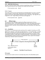
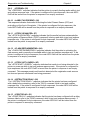
1.5.7 DN
(Direction)
This parameter is used to select the direction of the text. The only valid parameter for
direction is rightwards text. A selection of rightwards text would cause the characters to be
printed left to right.
1
Rightwards Direction
(default)
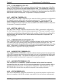
1.5.8 FO
(Field Orientation)
XB, YB, CI, SW, SH, AI, DN, FO, FJ, FW, CS, FC, CC
The values entered in this parameter are expressed in degrees. The normal orientation (0º)
is right side up as viewed from the front of the printer. The valid arguments are 0, 90, 180
and 270. The rotation is measured counter-clockwise.
0
90
180
270
0 degree
90 degree
180 degree
270 degree
(default)
XB, YB, CI, SW, SH, AI, DN, FO, FJ, FW, CS, FC, CC
1.5.9 FJ
(Field Justification)
The field justification or FJ controls the alignment, kerning, and the proportionality of text
and/or bar codes with respect to the type of composition used. Alignment is done side-toside (left, right, centered, or full justified to span the entire LSY distance) and vertically (on
or below baseline, which is an imaginary line extending from the starting coordinates along
the direction of the text), relative to the default (0 degree) orientation of text and/or bar
codes and the insertion point of the field. This means that whatever the direction and
LDSII Programming Guide - 880015-0123
15
Designing Using LDSII
Chapter 1
orientation may be; left will always be the left edge of the characters when the media exits
the printer.
Kerning is when one character in a proportional font can be slid under another character to
achieve a more appealing result. Kerning is enabled and used by default unless a value for
the FJ parameter is entered. If a value is entered then kerning would have to be selected
by adding “100” to the justification value.
Proportionality refers to whether the characters are all different widths or all the same. A
proportional font has characters that are mostly different widths. A mono-spaced font has
characters that are all the same width, except generally for punctuation.
When selecting the alignment value, text and/or bar codes will be aligned from the XB and
YB insertion point. The justified function, to be aligned, can be specified by using a
combination of the insertion point and the FW (Field Width) parameter so that the text is
spaced to run this entire distance.
The desired alignment value can be determined from the table below:
Composition
Horizontal
Vertical
Alignment
Above
Baseline
Below
Baseline
Horizontal Alignment
Vertical
Left
Center
Right
Justified
Top
11
12
13
14
Bottom
31
32
33
34
Add 100 for kerning and add 200 for mono-spacing to the FJ value to produce effects.
Table 4
Field Justifications
For Example: A typical European language would be left horizontal and normal vertical
alignment, which would be a value of “11” for the “FJ” parameter. If kerning was also
desired, the proper value would then be “111” and for mono spacing it would be “211”.
XB, YB, CI, SW, SH, AI, DN, FO, FJ, FW, CS, FC, CC
1.5.10 FW (Field Width)
The field width parameter sets the width of a text field, using the current unit of measure,
along the direction of composition. This is used to limit the physical width of the cell where
the appropriate data is to be placed. If the desired data is longer than the field width setting,
then characters outside the cell width setting will not be printed.
XB, YB, CI, SW, SH, AI, DN, FO, FJ, FW, CS, FC, CC
1.5.11 CS (Character Spacing)
This parameter adjusts the spacing between each character or the inter-character spacing.
The change is made relative to a default, where omitting this parameter or entering a “0”
causes the default to be used. The specified spacing value is in units of typesetting points,
where 1 point = 1/72”. Positive point values increase the default spacing while negative
16
LDSII Programming Guide - 880015-0123
Chapter 1
Designing Using LDSII
values reduce the default spacing. The point values are accurate to a single digit following
the decimal place (1.4 for example).
XB, YB, CI, SW, SH, AI, DN, FO, FJ, FW, CS, FC, CC
1.5.12 FC (First Character)
The FC parameter is used to select the first character to be used as data within the text
string data. This parameter is helpful in allowing several fields to use sections of the same
text string minimizing the amount of data transmitted. If the value specified for the FC
parameter is equal to or greater than the included data, the entire data string will be printed.
For Example, for the text string 0123456789, a FC value of 5 would start the data on the
fifth character and the resulting data would be 456789. This parameter is typically used in
conjunction with the CC (Character Count) parameter listed below.
XB, YB, CI, SW, SH, AI, DN, FO, FJ, FW, CS, FC, CC
1.5.13 CC (Character Count)
This parameter is used to determine the number of characters that will be used as data
within a text string. If the number of characters in the selected text string is more than the
quantity specified by the CC, then the remainder of the text string is ignored. If this
parameter is left blank then the entire text string will be used as the data. Using the same
example described in section 1.4.12, a CC value of 2 in conjunction with a FC value of 5,
would result in a value of 45 to be used as the data.
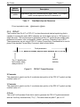
1.6
Text Entry Command - ^Tn)
The Text Entry command is used to define the actual data to be rendered using the output
identified by the CI parameter. This command starts with the “^Tn)” structure and then is
followed by the subject text or data. The “n” is an identifier that represents the subject text
lines and will use the formatting that has been placed in the corresponding “n” of the format
entry command (“Fn)”).
For features like graphics and/or line draw, this command is simply a placeholder for the
equivalent “^Fn)” command, so any text may be entered. When printing graphics, text
containing the graphic name or simply the word graphic should be entered and can be
helpful for debugging purposes. The same would be true when using the line draw feature
by entering the word “line” in the “^Tn)”, this also assists in debugging easier.
Note: To print either the caret (“^”) or the pipe (“|”) characters simply enter them twice
(example - “^^”).
LDSII Programming Guide - 880015-0123
17
Designing Using LDSII
Chapter 1
This text is what will
print out on the media.
^Tn)Your subject text is typed here.
Identifies the subject text
line number and
corresponds with the
same format line number.
Figure 5
18
Subject data is entered
immediately after the command
with no space between the
command and the text.
Text Entry Command
LDSII Programming Guide - 880015-0123
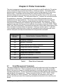
Chapter 2: Printer Commands
The script management commands may be issued inside a script file while the ^Dxx printer
control commands may be issued from inside or outside a script file. Commands will be
persistent and non-volatile if issued from outside a script file and temporary if issued from
inside a script. Commands that are issued from inside a script file will override the
persistent setting during the processing of the script file and then return to the value of the
previous persistent command. The commands require a “)” between the command and the
first parameter or argument. Commands that contain multiple parameters must be
separated with the comma delimiter. The printer control commands follow the standard
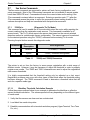
command preface (“^Dxxx”) structure and are divided into eight sub-categories. These
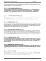
categories are identified by the “hundreds” digit as listed below. The commands are also
executed in the order that they are issued with the only exceptions being the ^D391, ^D566,
^D565, and ^D564 commands. Commands will return the current status and/or setting if the
^Dxx command is entered without an argument. Entering a question mark (“?”) after the
^Dxx command causes the printer to report the commands current setting as well as the
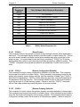
verbose description and help text associated with that particular command.
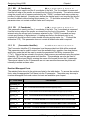
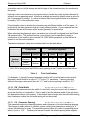
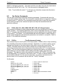
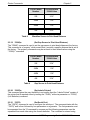
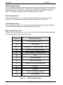
^Dxxx Series
Number
Series Number Command Definition
2xx
Formatting Commands
3xx
Operation Commands
4xx
Volatile Selection and Setting Commands
5xx
Configurable Selection Commands
6xx
Configurable Setting Commands
7xx
Configurable Enablement Commands
8xx
Reserved for future use.
9xx
Self Test and Factory Commands
Table 5
2.1
^Dxxx Series Commands
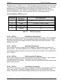
Script Management Commands
The script management commands deal specifically with scripts and control how scripts are
processed and executed. These commands are only valid when sent inside a script file.
Refer to the previous chapter for detailed description on working with script files and their
formatting requirements. Certain commands are always processed before other commands
with disregard to their placement. These commands include the ^D391, ^D566, ^D565,
^D564, and then the ^D200 command. The commands are processed in this order, if
present, and after processed the remaining commands are executed in the order they are
issued.
LDSII Programming Guide - 880015-0123
19
Printer Commands
Chapter 2
2.1.1
Begin Script - ^A)filename
This command is used to mark the beginning of a script file. The script may be saved into
the printer’s non-volatile flash memory if a title or filename is placed after the command.
The filename may contain to a maximum of 20 characters in length and include any
character from ASCII 0x20 and 0x41 to 0x7A (alphabetical characters plus [\]_’and SP
(space character)) with the exception of the caret (^) character. Script filenames can not
use a leading zero (“0”) or 0x30 characters. A script that contains a “filename” will only save
the script and will not process and print. The “^D350)filename” would be issued to recall
and process the saved script. If the script does not contain a “filename”, the script is
processed normally and will be volatile in nature.
2.1.2
Begin Temporary Script - ^AT)filename
This command is used to mark the beginning of a temporary or transient script file. The
script may be saved into the printer’s volatile RAM if a title or filename is placed after the
^AT) command. The filename may contain to a maximum of 20 characters in length and
include any character from ASCII 0x20 and 0x41 to 0x7A (alphabetical characters plus
[\]_’and SP (space character)) with the exception of the caret (^) character. Script filenames
can not use a leading zero (“0”) or 0x30 characters. Scripts saved in RAM report “*volatile*”
in the comments column to distinguish between volatile and non-volatile scripts. A script
that contains a “filename” will only save the script and will not process and print. The
“^D350)filename” would be issued to recall and process the saved script. If the script does
not contain a “filename”, the script is processed normally and will be volatile in nature.
Temporary scripts are not saved and are lost once a reset or power cycle occurs.
2.1.3
Format Entry Command - ^Fn)XB,YB,CI,SW,SH,AI,DN,FO,FJ,FW,CS,FC,CC
The Format Entry command is used to define the characteristics, placement and
representation of the corresponding text data of the individual fields. This command starts
with the “^Fn)” structure which is then followed by thirteen different parameters that define
and control the desired field. The “n” is an identifier that represents the field number being
formatted and corresponds to the equivalent “^Tn)” line. As with the ^Dxxx commands,
multiple parameters must be separated by the comma (“,”) delimiter. The format entry
command may be issued from outside a script but is typically created within a script file.
Unlike the “^Dxx)” commands and the script header, the Format Entry Command typically
does contain default values as there are no equivalent commands for the individual
parameters. The default values are discussed under the individual parameter descriptions.
Refer to section 1.5 for the individual parameters detailed descriptions.
2.1.4
Text Entry Command - ^Tn)text data
The Text Entry command is used to define the actual data to be rendered using the output
identified by the CI parameter. This command starts with the “^Tn)” structure and then is
followed by the subject text or data. The “n” is an identifier that represents the subject text
lines and will use the formatting that has been placed in the corresponding “n” of the format
entry command (“Fn)”).
For features like graphics and/or line draw, this command is simply a placeholder for the
equivalent “^Fn)” command, so any text may be entered. When printing graphics, text
containing the graphic name or simply the word graphic should be entered and can be
20
LDSII Programming Guide - 880015-0123
Chapter 2
Printer Commands
helpful for debugging purposes. The same would be true when using the line draw feature
by entering the word “line” in the “^Tn)”, this also assists in debugging easier.
Note: To print either the caret (“^”) or the pipe (“|”) characters simply enter them twice
(example - “^^”).
2.2
2xx Series Commands
The 2xx series commands control the formatting commands. Commands will return the
current status and/or setting if the ^Dxx command is entered without an argument. Entering
a question mark (“?”) after the ^Dxx command causes the printer to report the commands
current setting as well as the verbose description and help text associated with that
particular command.
2.2.1
^D200) LSX, LSY, GAP, DRM, SPD, DET, OFX, OFY (Script Header)
This command is followed by eight parameters that control the media layout as well as
printer operation. The beginning parameter (LSX) must be separated from the ^D command
with a “)” character and each following parameter must be separated by the delimiter, which
is the comma (“,”) by default. It is recommended that since the header is used to identify a
certain media configuration that all header parameters are included in a script file. Refer to
section 1.4 for additional information.
2.2.2
^D202)n
(Text Replacement Header)
This command may be used in place of the script header (“^D200)”) after a script containing
^Fn) formatting instructions has been processed. Parameter “n” is used to specify a script
that has been saved into the printer memory that will be used as the current script. The
“^D202)” command causes new text data to replace the corresponding text from the
previously processed script sent to the printer or by entering value for “n” a script saved in
memory. This provides a streamlined method for entering new data into an existing script
without having to send the header and formatting instructions again, thus improving
throughput. The data that needs to be replaced is sent after the “^D202)” command using
the corresponding ^Tn) command in the current script. To erase or clear a format line, you
would send the desired ^Tn) line and omit new data. To conserve text data from the
previous script, do not reference the line after the “^D202)” command.
For Example:
^AT)test
^D200)3,1,0.125,0,3,2,0,0
^F1)1.50,0.75,@normal_10,1,1,0,1,0,12
^F2)1.50,0.50,@normal_10,1,1,0,1,0,12
^F3)1.50,0.25,@normal_10,1,1,0,1,0,12
^T1)Text
^T2)Replacement
^T3)Example
^D300)1
^Z)
LDSII Programming Guide - 880015-0123
<-- saves a volatile file called "test"
<-- label header
<-- field #1 definition
<-- field #2 definition
<-- field #3 definition
<-- field #1 data
<-- field #2 data
<-- field #3 data
<-- print “1” copy command when recalled
<-- end script
21
Printer Commands
Chapter 2
^D202 Print Example #1
Text
Replacement
Example
The “^D202 Print Example #1” illustrates what the sample script listed above would
generate if recalled using the “^D350) command (“^D350)test”).
^D202 Print Example #2
^A)
^D202)test
^T3)Print Sample
^D300)1
^Z)
<-- start script
<-- recalls file “test”
<-- replace ^T3 data
<-- print 1 copy
<-- end script
Text
Replacement
Print Sample
The “^D202 Print Example #2” illustrates recalling the script from Example #1 (“test”) and
then replacing the data in text field #3 (“^T3”) from “Example” to “Print Sample”.
^D202 Print Example #3
^A)
^D597)1
^D202)test
^T1)
^T3)Print Sample
^D300)2
^Z)
<-- start script
<-- advance after print
<-- recalls file “test”
<-- replace/delete ^T1 data
<-- replace ^T3 data
<-- print 2 copies
<-- end script
Replacement
Print Sample
The “^D202 Print Example #3” illustrates adding a ^D command, recalling the script from
Example #1 (“test”), replacing text field #1 with blank space, replacing the data in text field
#3 (“^T3”) from “Example” to “Print Sample”, and increasing how many copies are printed
(“^D300)2”).
2.3
3xx Series Commands
The 3xx series commands control basic operation and list commands. Commands will
return the current status and/or setting if the ^Dxx command is entered without an
argument. The ^D3xx series commands are also required to be sent each and every time
because persistent or values set outside a script file are not retained. Entering a question
mark (“?”) after the ^Dxx command causes the printer to report the commands current
setting as well as the verbose description and help text associated with that particular
command.
22
LDSII Programming Guide - 880015-0123
Chapter 2
Printer Commands
2.3.1
^D300)n
(Print Command)
This command will print a label or a batch of labels where “n” controls how many labels of
the identical script are printed. When this command is used within a script file, it should be
placed at the end of the ^D commands. The “^D300)” command is equivalent to the ^P
(ASCII 0x10) control code.
2.3.2
^D305)1
(Infinity Print Command)
Issuing this command will initiate infinity printing. The printer will continue to print until the
machine is turned off. This command may be sent from outside or from inside a script file.
2.3.3
^D311)1
(Top-OF-Form)
This command uses the Label Present Sensor to detect the edge of the media and retracts
the leading edge of the media to the print head dot row or start position. The “^D311)”
command is equivalent to the ^O (ASCII 0x0F) control code.
2.3.4
^D312)n
(Form Feed)
This command causes the printer to feed or scroll a form size that is based upon the
previous script’s configuration where “n” controls how many copies are issued. The form is
determined by the last label size that was processed. This command can be used inside
and/or outside a script file. The “^D312)” command is equivalent to the ^L (ASCII 0x0C)
control code.
2.3.5
^D313)n1,n2
(Advance Media)
This command is used to advance the media by a programmable distance (n1) at a
programmable speed (n2). The distance and speed parameters are specified in the current
selectable units (“^D564)” and “^D565)”) commands. A negative distance for the n1
parameter causes the printer to retract the specified amount at the speed entered with the
n2 parameter.
2.3.6
^D315)n
(Calibrate Sensor Thresholds)
This command is used to recalibrate the registration mark sensor thresholds for proper
detection of registration marks used on the current media. This command is an interactive
command requiring the printer’s response set to VERBOSE mode or the “^D550)9”
command. The “n” parameter is the registration mark width and is entered using the current
unit of measure selected by the “^D564)” command. The calibration is done at the factory
and recalibration should only be issued when the installation of new sensors has occurred
or the original threshold does not function properly for the media being used. The
registration detection mode command “^D636)” must also be correctly set to the type of
media that is being used for successful calibration to occur. If this command is used
improperly, the printer may not be able to detect registration marks causing the print to be
out of registration.
LDSII Programming Guide - 880015-0123
23
Printer Commands
Chapter 2
2.3.7
^D323)n
(List Enablements)
The “^D323)” command will list the printers current configurable enablements along with
each of the individual enablement specific ^D7xx command. This command should only be
issued from outside a script file and not issued in a script file. The valid parameters for “n”
are listed below. If the ^D command is issued without a parameter, the default will be used.
The “^D323)” command is equivalent to the ^Y (ASCII 0x19) immediate control code.
1
2
through active port (default)
print out
2.3.8
^D324)n
(List Statistics)
This command is used to report the printer’s current status such as the firmware version,
communication parameters, memory information, and basic usage statistics. The “^D324)”
command is equivalent to the ^W (ASCII 0x17) control code.
1
2
through active port (default)
print out
2.3.9
^D325)n
(List Selections)
The “^D325)” command will list the printers current configured selections along with each of
the individual selection specific ^D5xx command. This command should only be issued
outside a script file. The valid parameters for “n” are listed below. If the ^D command is
issued without a parameter, the default will be used. The “^D325)” command is equivalent
to the ^U (ASCII 0x15) control code.
1
2
through active port (default)
print out
2.3.10 ^D326)n
(List Settings)
The “^D326)” command lists the printers current settings along with each of the individual
setting specific ^D6xx) commands. This command should only be issued outside a script
file. The valid parameters for “n” are listed below. If the ^D command is issued without a
parameter, the default will be used. The “^D326)” command is equivalent to the ^V (ASCII
0x16) control code.
1
through active port (default)
2
print out
2.3.11 ^D327)1
(List Status)
The “^D327)1” command will report the printers current status through the active port.
When the indicator light on the front panel changes from green to amber or red, this
command will provide information of the current status (i.e., >STOCK OUT<, >READY<,
>PAUSED<...). The actual response the printer sends depends on the printer response set
configuration, refer to the “^D550)” command for additional information. This command may
be issued inside or outside a script file. The “^D327)1” command is the queued or serialized
equivalent to the ^E (ASCII 0x05) immediate control code. Refer to Chapter 6 for the
available status messages.
24
LDSII Programming Guide - 880015-0123
Chapter 2
Printer Commands
2.3.12 ^D340)filename
(Load/Save File)
The “^D340)” command causes the printer to take the ensuing data transfer as a binary file
upload from the host. The file will then be permanently stored in the printer’s flash memory
until it is explicitly erased. The printer will currently accept the following file types: 1-bit
(monochrome) BMP graphics, and MCF’s (Microcom Corporation Converted Font). The file
transfer can be sent in uncompressed or PKZIP compatible compressed formats. A ^E
(0x05) character may be sent to the printer during the download without any negative
effects towards the file size. The ^D340) command has three parts, which are name, file
size, and comment. Both the name and file size are required while the comment is optional.
The filename and/or comment may contain to a maximum of 20 characters in length and
include any character from ASCII 0x20 and 0x41 to 0x7A (alphabetical characters plus
[\]_’and SP (space character)) with the exception of the caret (^) character. Script filenames
can not use a leading zero (“0”) or 0x30 characters.
When saving MCF files, the chosen name should include the “_” (underscore character)
followed by the point size; see the examples below.
Command Syntax: ^D340)filename, file size, comment (optional)
Example 1: “^D340)swiss721_10,3092”
Example 2: “^D340) graphic, 2862, my graphic”
Example 2 would save a BMP file titled “graphic” and a comment “my graphic” into the
printer’s flash memory. The printer will automatically detect the file type of the ensuing data
and save it as such.
2.3.13 ^D341)type
(List Catalog)
This command is used to list the files stored in the printer’s flash memory. The list reports
the files name (user file CI), any associated comments, file type, and the file size of all file
types. This command should only be issued from outside a script file and not entered from
a script file. Issuing this command with the “?” as the argument also causes the listing to be
generated. The ^D341) command may contain a search string type to limit a search for
specific file types. The valid parameters for “type” are listed below.
1
2
4
5
List all file types
List only graphic file types
List only bitmapped font file types
List only script file types
2.3.14 ^D342)filename
(Delete File)
This command is used to delete a stored font, graphic, or script. The filename must match a
saved file name and/or contain the wild card character (*) for the stored file to be properly
deleted. This would include any space characters that were entered when saving the file.
LDSII Programming Guide - 880015-0123
25
Printer Commands
Chapter 2
The “^D341)” command is useful in determining the exact filename and the valid wild card
structure is listed below.
*x
x*
x*y
*x*
- deletes filenames that end with character string x.
- deletes filenames that begin with character string x.
- deletes filenames that begin with character string x and end with string y.
- deletes filenames where character string x is found anywhere in the filename.
2.3.15 ^D343)filename
(List Script)
This command lists the contents of the specified script that has been saved in the printer’s
flash memory to the active port.
2.3.16 ^D345)filename
(Load Volatile File)
The “^D345)” command causes the printer to take the ensuing data transfer as a binary file
upload from the host without saving to the printer’s flash memory. The file is volatile in
nature and will lost when power is cycled. The printer will currently accept the following file
types: 1-bit (monochrome) BMP graphics, MCF (Microcom Corporation Converted Font),
and user created script files. The file transfer can be sent in uncompressed or PKZIP
compatible compressed formats. A ^E (0x05) character may be sent to the printer during
the download without any negative effects towards the file size. The “^D345)” command
has two parts, which are the file name and file size.
The filename may contain to a maximum of 20 characters in length and include any
character from ASCII 0x20 and 0x41 to 0x7A (alphabetical characters plus [\]_’and SP
(space character)) with the exception of the caret (^) character. Script filenames can not
use a leading zero (“0”) or 0x30 characters.
When saving MCF files, the chosen name should include the “_” (underscore character)
followed by the point size; see the examples below.
Command Syntax: ^D345)filename, file size
Example 1: “^D340)swiss721_10,3092”
Example 2: “^D340) graphic, 2862”
Example 2 would save a BMP file titled “graphic” into the printer’s volatile RAM memory.
The printer will automatically detect the file type of the ensuing data and save it as such.
2.3.17 ^D346)1
(Defragment Flash Files)
The “^D346)” command is used to Defragment or free up used flash memory file area.
Issuing this command causes the printer to delete the user area of flash memory and rewrite
the contents copied to RAM back into the flash memory. During the Defragment process,
the printer’s power should not be interrupted as the printer’s file area is stored in volatile
RAM until defragmenting is completed. If power is lost while using the “^D346)” command
the printer’s flash memory contents will become corrupted and the printer will not function.
The “>FLASH DEFRAGMENTING<” message is reported in response to an enquiry
26
LDSII Programming Guide - 880015-0123
Chapter 2
Printer Commands
command until the defragmenting operation has completed. The “^D360)”, “^D324)”, and
^W commands are helpful in determining when the printer requires defragmenting by listing
the amount of available flash memory. If the printer responds with the “>INADEQUATE
FLASH SPACE<” message, the printer’s flash memory is either full or requires
defragmentation to free up additional flash memory. The printer typically only requires the
defragment process when files are being saved and deleted into flash memory and not
when using the ^AT) command which only saves script into RAM. The “^D346)” may be set
to run automatically on a power-up when the available flash memory falls below 10% of the
total flash file area with enabling the “^D760)” command.
2.3.18 ^D350)filename
(Execute Script)
This command recalls and processes a script that has been saved in the printer’s flash
memory or volatile scripts that are currently in RAM.
2.3.19 ^D360)1
(List Memory Available)
This command lists the current RAM and Flash memory available. The available RAM is
listed and then the available Flash memory is reported. The memory types are separated
by the comma (“,”) delimiter.
2.3.20 ^D365)?
(List Status Response List)
This command generates a list of the status responses and sends it to the active port. The
list contains the byte, text, and verbose equivalent responses. Refer to the “^D550)“
command regarding the byte, text, and verbose response sets. This command should only
be issued outside a script file. The available status responses are listed in the Table 6.
Byte Mode
Responses
(ASCII)
Text / Verbose Mode Response Equivalent
0x01
>STOCK OUT<
0x02
>STOCK OVERADVANCED<
0x03
>STOCK JAMMED<
0x04
>INCORRECT STOCK<
0x06
>OK<
0x10
>CUTTER JAMMED<
0x11
>CUTTER INOPERATIVE<
0x12
>CUTTER WATCHDOG STOPPED CUTTER<
0x13
>CUTTER WATCHDOG WON’T RESET<
0x1C
>MISSING LABELS<
0x1D
>INCOMPLETE FORM<
0x20
>CATCH TRAY FULL<
0x21
>INPUT 1<
LDSII Programming Guide - 880015-0123
27
Printer Commands
28
Chapter 2
Byte Mode
Responses
(ASCII)
Text / Verbose Mode Response Equivalent
0x22
>INPUT 2<
0x30
>SCRIPT ERROR<
0x31
>INVALID PARAMETER<
0X32
>PARSER ERROR<
0x40
>COMM ERROR<
0X51
>FLASH ERROR<
0x80
>RESTARTED<
0x81
>READY<
0x82
>BUSY<
0x83
>PAUSED<
0x84
>PRINTING<
0x85
>FEEDING<
0x86
>LABEL/TAG PRESENT<
0x87
>STOCK ADVANCED<
0x8A
>FLASH DEFRAGMENTING<
0x8D
>LABEL/TAG NOT PRESENT<
0x8F
>STOCK NOT LOADED<
0x90
>RETRACTION DELAY<
0x91
>PRINT DELAY<
0xB0
>FLASH MEMORY LOW<
0xC0
>BUTTON 1 TAPPED<
0xC1
>BUTTON 1 HELD<
0xD0
>TEMPERATURE OUT OF RANGE<
0XD1
>NONEXISTENT COMMAND<
0xD2
>INCOMPLETE COMMAND<
0xD3
>ZIP FILE ERROR<
0xD4
>FILE CONVERSION ERROR<
0xD5
>UNSUPPORTED FILE TYPE<
0xD6
>FILE NOT FOUND<
0xD7
>INADEQUATE ACCESS MODE<
0xD9
>FILE IS READ ONLY<
0xDA
>INADEQUATE FLASH SPACE<
LDSII Programming Guide - 880015-0123
Chapter 2
Printer Commands
Byte Mode
Responses
(ASCII)
Text / Verbose Mode Response Equivalent
0xDB
>I/O FAILURE<
0xDC
>FONT/GRAPHIC NOT FOUND<
0xDD
>BAD FILENAME<
0xE1
>SWITCH 0 ACTUATED<
0xE2
>SWITCH 1 ACTUATED<
0xE3
>SWITCH 2 ACTUATED<
0xE4
>TOF SWITCH ACTUATED<
0xF0
>FIELD OFF IMAGE<
0xF1
>COMPOSITION ERROR<
0XF2
>GRAPHIC TOO LARGE<
0xFF
>POWERED DOWN<
Table 6
^D365) Status Response List
2.3.21 ^D390)1
(Reset Printer)
This command instructs the printer to perform a reset through software, which duplicates a
hard reset. This command may be issued from either inside or outside a script file. Caution
should be used if issued from inside a script before sending data after a reset due to the
power up time. It is a good idea to issue an Enquiry command (“^D327)1” or ^E) before
sending data after a reset to verify that the printer has returned to a >READY< status. The
“^D390)1” command is the queued equivalent to the immediate ^R (ASCII 0x12) control
code.
2.3.22 ^D391)1
(Restore Configuration Defaults)
This command is used to restore configuration defaults to a known state. This command
may be sent from inside or outside a script. If this command is sent inside a script file, the
printer will transiently restore factory defaults, with the exception of Model Type (“^D501)”)
and Serial Port parameters (“^D670)”), before executing any other command regardless of
the placement within the script file. This command should be sent to the printer outside a
script file as a part of a Flash memory update. Failure to issue the “^D391)1” command
after a Flash code update may cause the printer to become unstable.
2.3.23 ^D392)1
(Restore Property Defaults)
This command is used to restore the printer’s property command defaults to a known state.
This command may be sent from inside or outside a script. If this command is sent inside a
script file, the printer will transiently restore factory defaults. This command should be sent
to the printer outside a script file as a part of a Flash memory update. Failure to issue the
LDSII Programming Guide - 880015-0123
29
Printer Commands
Chapter 2
“^D392)1” command after a Flash code update may cause the printer to become unstable.
A reset (^D390) and/or power cycle is required for this command to complete.
2.3.24 ^D394)1
(Draw Platen Roller Compensation Line)
The “^D394)1” command prints 10” lines in the “Y” direction that are used to correct any
tolerance issues with the printer’s drive roller. This command is intended to be used in
conjunction with the “^D646)” command. Continuous media should be used when using the
“^D394)1” command.
2.4
5xx Series Commands
The 5xx series commands control the printer’s configurable selections and may be issued
from outside and/or inside a script file. Commands will return the current status and/or
setting if the ^Dxx command is entered without an argument. Entering a question mark (“?”)
after the ^Dxx command causes the printer to report the commands current setting as well
as the verbose description and help text associated with that particular command.
2.4.1
^D501)n
(Select Emulation Mode)
This command is used to select the various products and their command structure that can
be emulated by entering the “n” parameter. Once the printer has been set to a specific
emulation mode, the commands will then follow the rules of that particular product. This
command should only be issued from outside a script and not from within a script. The
printer will force commands to their default LDSII settings when returning to the LDSII mode.
The “n” parameter is used to select the desired Model of the printer that will be used.
Selecting this parameter automatically adjusts the necessary changes within the printer.
The printer returns the current mode separated by <CR> characters when issued.
1
2
LDSII Language
Limited 410ECA
2.4.2
^D506)n
(Select Cutter Type)
This command is used to select the type of cutter that is installed on the printer. The valid
parameters for “n” are listed below. The printer has to be reset and/or a power cycle must
occur after setting this command. To adjust the dispense distance for the available cutters,
refer to the “^D642)” command.
The recommended “^D642)” value for the guillotine cutter dispense distance for the Model
426 printer is 0.84” (21mm) but may vary due to mechanical tolerances and/or printer model
numbers.
The recommended “^D642)” value for the rotary cutter dispense distance for the Model 426
printer is 0.98” (25mm) but may vary due to mechanical tolerances and/or printer model
numbers.
0
1
2
30
None
Guillotine Cutter
Rotary Cutter
LDSII Programming Guide - 880015-0123
Chapter 2
Printer Commands
2.4.3
^D507)n
(Select Printed Media Handler)
This command is used to select the type of Printed Media Handler (PMH) that is installed on
the printer. The valid parameters for “n” are listed below. Once this command is changed,
printer power needs to be cycled before changes take effect.
0
1
2
3
None
Catch Tray type 1
PMP (Printed Media Presenter) type 1
Stacker 160P
2.4.4
^D508)n
(Select Label Present Detector Type)
The “^D508)” command selects from among the available label present detector (LPD)
types. The LPD is set to reflective if using with a Model 426 printer and transmissive type 1
if the printer is used in conjunction with the catch tray. If selections 1 through 3 are used the
printer will report either the >LABEL\TAG PRESENT< or 0x86 when media blocks the
sensor depending on the configured response set or “^D550)” command. When selections
1 through 3 are used and media does not block the LPD either the >LABEL\TAG NOT
PRESENT< or 0x8D when media blocks the sensor depending on the configured response
set or “^D550)” command. A selection, 1 through 3, is also required when using the
Dispense mode or “^D597)” or the dispense mode command with automatically retract
ignoring the LPD signal. This command is also used to control the optional INPUT 2 sensor
using selections 4 through 7. These settings configure how and when the >INPUT 2< or
0x22 message is reported. The valid parameters for “n” are listed below.
0
1
2
3
4
5
6
7
None
Reflective
Transmissive type 1
Transmissive type 2
Send only a message when INPUT2 signal is active (LOW)
Send only a message when INPUT2 signal is inactive (HIGH)
Assert an error when INPUT2 signal is active (LOW)
Assert an error when INPUT2 signal is inactive (HIGH)
2.4.5
^D509)n
(Select INPUT1 Response Polarity and Action)
The “^D509)” command selects whether the printer issues an >INPUT 1< or 0x21 message,
depending on the “^D550)” command setting, when the optional INPUT 1 sensor’s signal is
active (LOW), or when it is inactive (HIGH), and whether it sets an error of just sends a
message through the printer’s active port. The “^D509)” command is set to “3” when using
the optional Catch Tray assembly with the printer.
0
1
2
3
4
No response when INPUT 1 signal changes
Send only a message when INPUT 1 signal is active (LOW)
Send only a message when INPUT 1 signal is inactive (HIGH)
Assert an error when INPUT 1 signal is active (LOW)
Assert an error when INPUT 1 signal is inactive (HIGH)
LDSII Programming Guide - 880015-0123
31
Printer Commands
Chapter 2
2.4.6
^D541)n
(Select Button 1 Response)
This command is used to select the operation and response of Button 1 which is typically
referred to as the print button. When set to a value of “1”, the printer will reprint the
previously printed script with a short button press and if the button is held, the printer will
continuously feed media until the button is released. When set to a value of “2”, the printer
will form feed with a short or brief button press and continuous feed if held. A setting of “3”
causes the short button press to send the “>BUTTON 1 TAPPED<” response to the active
port while holding the button in continuously feeds media until the button is released. A
setting of “4” causes the short button press to send the “>BUTTON 1 TAPPED<” response
to the active port while holding the button in sends the “>BUTTON 1 HELD<” response
through the active port. A setting of “5” causes the short button press to initiate a TOF (TopOf-Form) or ^D311 command while holding the button in continuously feeds media until the
button is released.
1
2
3
4
5
Short press = reprint; button held = continuous feed (default)
Short press = form feed; button held = continuous feed
Short press = “>BUTTON 1 TAPPED<” response;
button held = continuous feed
Short press = “>BUTTON 1 TAPPED<”;
button held = “>BUTTON 1 HELD<”
Short press = Initiates a TOF (^D311); button held = continuous feed
2.4.7
^D550)n
(Select Printer Response Set)
This command is used to select among the available response sets the printer offers. The
response sets determine how the printer will react to commands, functions, and enquiry
responses. Issuing a ^Dxx command without a parameter will report the commands current
setting regardless of the selected response set. Descriptive text is reported by issuing the
question mark character (“?”) after a ^Dxx command and is available in all response sets.
For Example: Issuing the “^D550)? <CR>” command sequence would cause the printer to
report text that describes the commands current setting as well as the commands operation
and valid settings.
Refer to the following sample dialog:
^D550 n -- Selects response mode
1 - TEXT -- Text responses (default)
2 - BYTE -- Byte-encoded responses
9 - VERBOSE -- Text responses with command help text
and confirmations of settings
Current setting is: 1.
Use a selection index to change the setting.
Text: If text responses are selected, the printer responds with simple text responses to
enquiries and error conditions. Commands that are issued without an argument will return
that commands current setting without descriptive text while in the text mode response set.
The printer is capable of multiple line responses so the final response is terminated with a
“CR LF” or “0x0D 0x0A” sequence to assist in programming. The only response that is
32
LDSII Programming Guide - 880015-0123
Chapter 2
Printer Commands
automatically generated is the >POWERED DOWN< response and occurs when power is
removed from the printer.
Byte: When the byte response set is selected, the printer returns all responses in binary
form. Commands that are issued without an argument will return that commands current
setting without descriptive text while in the byte mode response set. The printer is capable
of multiple line responses so the final response is terminated with the ^Z or 0x1A character
to assist in programming. The only response that is automatically generated is the
>POWERED DOWN< or 0xFF response and occurs when power is removed from the
printer.
Verbose: If verbose responses are selected, the printer will include elaborate text help
about commands when that command is issued without an argument, a summary of any
action that has just resulted from a command, and listings of printer parameters, where the
listed values are each identified by descriptive text. This mode is very helpful when learning
how to use the printer for the first time and is not intended to be used for actual
programming.
1
2
9
Text (Default)
Byte
Verbose
2.4.8
^D564)n
(Select Measurement Units)
This command is used to select the prevailing unit of measure the printer will use. Some
commands and/or calculations use a constant unit of measure and will not change with the
issuance of this command. These commands and/or calculations that use a constant unit of
measure are noted in their respective descriptions. This command is always the first
command to be processed by the printer regardless of the placement within a script. This is
helpful in forcing a unit of measure for troubleshooting and support capabilities.
1
2
Inches
Millimeters
2.4.9
^D565)n
(Select Speed Units)
This command is used to select the desired unit of measure used for the speed parameter.
This command is independent from the “^D564)” command. The valid selections for the “n”
parameter are listed below with the default being a “1” (Inches). This command is always
processed first in a script or just after the “^D564)” command by the printer regardless of the
placement within a script. This is helpful in forcing a unit of measure for troubleshooting and
support capabilities.
1
2
Inches per Second (ips)
Centimeters per Second (cm/sec)
LDSII Programming Guide - 880015-0123
33
Printer Commands
Chapter 2
2.4.10 ^D566)n
(Select Temperature Units)
The “^D566)” command is used to select the temperature unit of measure the printer will
use for displaying the print head temperatures in degrees. This command is always
processed first in a script or just after the “^D564)” and “^D565)” commands by the printer
regardless of the placement within a script. This is helpful in forcing a unit of measure for
troubleshooting and support capabilities.
1
2
Fahrenheit
Centigrade
2.4.11 ^D567)filename
(Select Power-up Script)
The “^D567)” command is used to select the script that is processed on a printer power-up.
It is used in conjunction with the “^D720)” command to automatically process the selected
script on a power-up. Issuing the “^D567)” without a parameter builds and lists the scripts
that have been saved into the printers flash memory. The filename may contain to a
maximum of 20 characters in length and include any character from ASCII 0x20 and 0x41 to
0x7A (alphabetical characters plus [\]_’and SP (space character)) with the exception of the
caret (^) character. Script filenames can not use a leading zero (“0”) or 0x30 characters.
2.4.12 ^D570)n
(Select Active Port)
The “^D570)” command is used to select the printer’s active port. When the Autodetect is
selected the printer will automatically determine and set the port based on which port is
connected at powerup. If both serial and USB ports are connected, the autodetect will
select the USB as the active port. If autodetect is selected and neither the Serial nor the
USB is connected at power up, the Serial port will be selected as the active port. The
Autodetect feature will only determine the active port at power up and will continue to use
the selected port for the duration of the power up time. The valid parameters for “n” are
listed below.
0
1
2
5
Autodetect (Serial/USB)
RS-232 Serial Port
USB Type 1 (serial port disabled)
Wired Ethernet (serial port disabled)
2.4.13 ^D581)n
(Select Stock Out Handling Method)
This command is used to select the procedure the printer will use when handling >STOCK
OUT< conditions. The valid arguments for “n” are listed below. A selection of “1” instructs
the printer to immediately halt on a >STOCK OUT< condition. A button press clears the
error condition and reprints the last label format. A selection of “2” instructs the printer to
finish printing the current format before halting when a >STOCK OUT< condition occurs. A
button press clears the error condition and printing is resumed, if a print job is in process,
without reprinting the last script. If the printer could not finish the last script, the
>INCOMPLETE FORM< or 0x1D error response is generated along with the >STOCK
OUT< message. Once this occurs a button press is used to clear the error and the last
script that was incomplete is reprinted.
1
34
Immediate halt upon detection of stock-out.
LDSII Programming Guide - 880015-0123
Chapter 2
Printer Commands
2
Finish current label before halting.
2.4.14 ^D597)n
(Select Dispense Mode)
This command may be used for either Peel-N-Dispense and/or Tag/Tear dispense methods.
The Tag/Tear dispense method is when the perforation of a tag that has printed is advanced
out to the peel edge to make removal easier. The Peel-N-Dispense method is when die-cut
media is used and advanced so that the “peeled” media stays on the peel edge after
printing. The “n” is used to adjust the dispense methods, according to the list below, and
may be issued from outside a script or from within a script file. Depending on the desired
dispense method, the value for advancing to the peel or tear edge varies. To adjust the
dispense distance, refer to the “^D642)” command. A LPD (Label Present Detector) and a
“^D508)” selection are both required fro this command to properly function. If a “^D508)”
selection is omitted or if a LPD does not exist on the printer, the media will immediately
retract after printing has stopped.
The >STOCK ADVANCED< or 0x87 response is generated when the printer has advanced
the media to the desired dispense point. This response will be reported until the media is
removed or the “^D641)” delay time has expired causing the media to be retracted. When
the media is in the advanced position, the indicator light is solid amber in color.
The recommended “^D642)” value for the Tag/Tear dispense method for the Model 426
printer is 0.512” (13mm) but may vary due to mechanical tolerances and/or printer model
numbers.
The recommended “^D642)” value for the Peel-N-Dispense dispense method for the Model
426 printer is 0.472” (12mm) but may vary due to mechanical tolerances and/or printer
model numbers.
Valid selections for the “n” parameter –
0
No Advance/Retract – This will disable the Dispense mode.
1
Advance after every label (LTS Enabled) – Causes the label or tag
perforation to be advanced to the peel edge after every label is printed.
Before the printer retracts, it will wait for both the label to be taken and
any advance delay time setting.
2
Advance after copies count (LTS Enabled) – Causes the label or tag
perforation to be advanced to the peel edge after the set copies count
has been reached. Before the printer retracts, it will wait for both the
label to be taken and any advance delay time setting.
3
Advance when idle (LTS Disabled) – This will cause the label or tag
perforation to be advanced to the peel edge when the printer has no
pending data on the communications port. When new data is sent
through the port the printer will retract and then begin the printing
process. This command should be issued outside a script file and not
within a script file for proper operation.
LDSII Programming Guide - 880015-0123
35
Printer Commands
2.5
Chapter 2
4
Advance after every label (LTS Disabled) - Causes the label or tag
perforation to be advanced to the peel edge after every label is printed.
Before the printer retracts, it will wait only for any advance delay time
setting.
5
Advance after copies count (LTS Disabled) - Causes the label or tag
perforation to be advanced to the peel edge after the set copies count
has been reached. Before the printer retracts, it will only wait for any
advance delay time setting.
6xx Series Commands
The 6xx series commands control the configurable settings and may be issued outside
and/or inside a script file. Commands will return the current status and/or setting if the ^Dxx
command is entered without an argument. Entering a question mark (“?”) after the ^Dxx
command causes the printer to report the commands current setting as well as the verbose
description and help text associated with that particular command.
2.5.1
^D631)n
(Set Media Width)
This command specifies the width of the media using the current selected prevailing unit of
measure selected by the “^D564)” command. The maximum width is the width of the print
head installed on the printer. This command is also a parameter in the “^D200)” script
header command. See also, LSX.
2.5.2
^D632)n
(Set Media Height)
This command specifies the height of the media using the current selected prevailing unit of
measure selected by the “^D564)” command. The maximum LSY height is 24”. This
command is also a parameter in the “^D200)” script header command. See also, LSY.
2.5.3
^D633)n
(Set GAP Size)
This command sets the height distance, as viewed inside the printer, of the registration mark
that identifies the label and/or tag size and is entered using the current selected prevailing
unit of measure selected by the “^D564)” command. This would be the backing material
found between die-cut labels, blowhole sense mark, and/or the blackline height. This
command is also a parameter in the “^D200)” script header command. See also, GAP.
2.5.4
^D634)n
(Distance To Registration Mark)
This command is only used when the registration mark is not located at the edge of the
media. The “DRM” is the distance from the leading edge of the media to the beginning of
the registration mark and is entered using the current selected unit of measure. This
command is also a parameter in the “^D200)” script header command. See also, DRM.
36
LDSII Programming Guide - 880015-0123
Chapter 2
Printer Commands
2.5.5
^D635)n
(Set Print Speed)
The “^D635)” command sets the print speed of the printer using the current selected unit of
measure. Parameter “n” has a range of 1-6 inches per second or 2.54 - 15.24 cm/second.
This command is also a parameter in the “^D200)” script header command. See also, SPD.
2.5.6
^D636)n
(Set Detection Mode)
This command selects the type of method the printer uses for detecting registration marks
on the different media types. A selection of a “0” disables the detection of registration marks
and is used in conjunction with media that does not contain a registration mark like
continuous media. A selection of a “1” uses the reflective detection method and is used
when detecting registration marks located on the bottom side of the media. A selection of a
“2” uses the transmissive detection method which can be used with any type of media but is
not recommended when only detecting registration marks located on the bottom side of the
media. A selection of a “3” also uses the transmissive detection method and is used in
conjunction with media containing a blowhole. Both upper and lower gap detectors are
required for stock out detection regardless of the type of registration mark detection. This
command is also a parameter in the “^D200)” script header command. See also, DET.
0
1
2
3
None
Blackline
Die-cut
Blowhole
(gap sensors are disabled)
(lower gap sensor is enabled)
(upper and lower gap sensors are enabled)
(upper and lower gap sensors are enabled)
2.5.6.1
Detection Mode - None (0)
This mode is usually used with continuous media. Even though it is not necessary to sense
a registration mark, it is still important that the Upper and Lower Sensors are vertically
aligned to sense out-of-stock or stock out conditions.
Upper Sensor
Detector
Emitter
(Not Used)
Label
Stock
Emitter
Detector
(Not used)
Lower Sensor
Figure 6
Detection Mode - None
LDSII Programming Guide - 880015-0123
37
Printer Commands
Chapter 2
2.5.6.2
Detection Mode - Blackline (1)
This detection mode is used when a black line on the underside of the media is used to
register the labels. The Lower Sensor detector “senses” the amount of light reflected off of
the label from the Lower Sensor emitter. While registration is determined by the Lower
Sensor only in this mode, the upper gap sensor is used for out-of-stock or stock out
conditions.
Upper Sensor
Detector
Emitter
(Not Used)
Label
Emitter
Detector
Lower Sensor
Figure 7
Detection Mode - Blackline
2.5.6.3
Detection Mode - Die-cut (2) and Blow-hole (3)
Die-cut sensing refers to die-cut label registration where the difference in the transparency
of [label] and [label + backing] is detected (gap between labels is registration point).
Blow-hole sensing refers to label stock with holes punched out as registration marks. In this
case, the Upper and Lower Sensors must be aligned so that the hole in the stock passes
over the sensors.
Dies-cut and blow-hole use the same basic method of detection. However, because of the
difference in light intensity and stock out detection, they each require their own Detection
Mode setting (^D636).
38
LDSII Programming Guide - 880015-0123
Chapter 2
Printer Commands
Upper Sensor
Detector
Emitter
(Not Used)
Label
Stock
Emitter
Detector
(Not used)
Lower Sensor
Figure 8
Detection Mode - Die-cut and Blowhole
2.5.7
^D637)n
(Offset X Direction)
This command moves or offsets all fields in the “X” direction without altering the field’s
insertion points. The value is entered using the current selected unit of measure. This
command is also a parameter in the “^D200)” script header command. See also, OFX.
2.5.8
^D638)n
(Offset Y Direction)
This command moves or offsets all fields in the “Y” direction without altering the field’s
insertion points. The value is entered using the current selected unit of measure. This
command is also a parameter in the “^D200)” script header command. See also, OFY.
2.5.9
^D639)n
(Set Centering Offset)
The “^D639)” command is used to set the image position offset in the X direction
independently of OFX or “^D637)” command. This command is used to compensate for
mechanical misalignments that can not be adjusted mechanically. The value is entered
using the current selected unit of measure or “^D564)” command. This command is a
“property” which means that it controls a specific distance that is set at the factory. The
property commands may be set back to their default values using the “^D392)1” command.
2.5.10 ^D640)n
(Set Delay Time Between Labels)
This command delays the printing between labels in a batch. The value for “n” is entered in
decimal seconds and has a maximum of 15 seconds.
2.5.11 ^D641)n
(Set Retraction Delay Time)
This command is used in conjunction with the dispense modes (“^D597)” command) and/or
when a cutter is used. The delay controls how long the media is presented before being
retracted. The value for “n” is entered in decimal seconds with a 15 second maximum.
LDSII Programming Guide - 880015-0123
39
Printer Commands
Chapter 2
2.5.12 ^D642)n
(Set Advance/Retract Distance)
This command is used to set the distance the media advances and retracts after printing
while in dispense modes (“^D597)” command) or when a cutter is installed. The distance
“n” is entered in based on the unit of measure selected by the “^D564)” command.
The recommended “^D642)” value for the guillotine cutter dispense distance for the Model
426 printer is 0.91” (23.1mm) but may vary due to mechanical tolerances and/or printer
model numbers.
The recommended “^D642)” value for the rotary cutter dispense distance for the Model 426
printer is 0.91” (26.67mm) but may vary due to mechanical tolerances and/or printer model
numbers.
The recommended “^D642)” value for the Tag/Tear dispense method for the Model 426
printer is 0.512” (13mm) but may vary due to mechanical tolerances and/or printer model
numbers.
The recommended “^D642)” value for the Peel-N-Dispense dispense method for the Model
426 printer is 0.472” (12mm) but may vary due to mechanical tolerances and/or printer
model numbers.
2.5.13 ^D643)n
(Set Print Head to LPD Distance)
This command sets the distance from the print head to the LPD (Label Present Detector)
using the unit of measure selected by the “^D564)” command. This distance is the distance
media is retracted after reaching the LPD so that the media is properly positioned at the
print head. The distance is entered using the current unit of measure selected by the
“^D564)” command. This command is a “property” which means that it controls a specific
distance that is set at the factory. The property commands may be set back to their default
values using the “^D392)1” command.
2.5.14 ^D644)n
(Set Idle Recognition Delay)
The “^D644)” command is used to set the time after a printer goes idle before idleness is
recognized and is used in conjunction with the “^D597)3” command. The value for “n” is
entered in decimal seconds, with tenths of a second resolution.
2.5.15 ^D645)n1
(Set Advance/Retract Speed)
This command is used to set the speed that the printer advances and retracts while in a
“^D597)” dispense mode. The value entered is based on the current unit of measure or
“^D565)” command setting. If media slippage occurs, the speed should be lowered to
reduce this from reoccurring.
2.5.16 ^D646)n
(Set Platen Roller Compensation)
This command is used to set the drive roller compensation factor to accommodate the
tolerance of the drive roller. This command is set at the factory and should only be changed
if a new drive roller is installed. The value for “n” is entered using the current unit of
measure that is set by the “^D564)” command and is the distance of the lines generated by
40
LDSII Programming Guide - 880015-0123
Chapter 2
Printer Commands
the “^D394)1” command. This command is a “property” which means that it controls a
specific distance that is set at the factory. The property commands may be set back to their
default values using the “^D392)1” command.
2.5.17 ^D647)dc,dp
(Set Print Head Parameters)
The “^D647)” command is used to identify and specify the values for the print head installed
on the printer. The “dc” parameter specifies the “dot count” or total number of dots on the
print head while the “dp” or “dot pitch” identifies the dots per millimeter value. This
command is available in all access modes with the exception being LOCKOUT mode only.
This command is typically set at the factory and never changed. Refer to the following table
for the available print heads and their appropriate values. This command is a “property”
which means that it controls a specific distance that is set at the factory. The property
commands may be set back to their default values using the “^D392)1” command.
Print Head Part
Number
Printer Model
Number
dc
Parameter
dp
Parameter
630015-0000
226 – 203 DPI
406
8
630018-0000
326M – 203 DPI
640
8
630021-0000
326M – 300 DPI
960
11.808
630020-0000
426M – 203 DPI
832
8
630019-0000
426M – 300 DPI
1280
11.808
630014-0000
426 – 203 DPI
832
8
630017-0000
426 – 300 DPI
1280
11.808
Table 7
Print Head Parameters
2.5.18 ^D648)n
(Set Blackline Sensor to Print Head Distance)
The “^D648)” command is used to set the blackline sensor to print head distance at the
factory. This command is a “property” which means that it controls a specific distance that
is set at the factory. The property commands may be set back to their default values using
the “^D392)1” command.
LDSII Programming Guide - 880015-0123
41
Printer Commands
Chapter 2
Table 8
Printer Model
Number
Recommended
^D648 Value
226
2.32”
326M
1.36”
426M
1.36”
426
2.32”
Blackline Sensor to Print Head Distance
2.5.19 ^D649)n
(Set Gap Sensor to Print Head Distance)
The “^D649)” command is used to set the gap sensor to print head distance at the factory.
This command is a “property” which means that it controls a specific distance that is set at
the factory. The property commands may be set back to their default values using the
“^D392)1” command.
Table 9
Printer Model
Number
Recommended
^D649 Value
226
2.34”
326M
1.38”
426M
1.38”
426
2.34”
Gap Sensor to Print Head Distance
2.5.20 ^D655)n
(Set Labels Printed)
This command gives the user the ability to set and/or reset the “Labels Printed” counter of
the printer that is reported either by issuing the “^D655)” without a parameter or “^D324)”
(List Statistics) command.
2.5.21 ^D670)
(Set Serial Port)
The “^D670)” command is used to configure the serial port. The command starts with the
“^D670)” and is then followed by four parameters or arguments. The first parameter must
be separated from the ^D command by a space and the following parameters must be
separated from each other using the comma delimiter. The command is entered using
42
LDSII Programming Guide - 880015-0123
Chapter 2
Printer Commands
following structure, ^D670) b, p, d, s. When changing the serial parameters, the host needs
to be set to the new serial parameters that take effect immediately after setting. If the host
parameters are not changed to the correct settings, the host and the printer will not
communicate properly. The “^D670)” command defaults to 9600,n,8,1 when the printer
enters the diagnostic mode by pressing the print button in while applying power.
Command Syntax: ^D670) b, p, d, s
Parameter
Parameter
Description
Valid Arguments
b
Baud rate
1200,9600,19200,38400,57600,115200,230400
p
Parity
n = none, o = odd, e = even
d
Data word width
7, 8
s
Stop bits
1, 2
Table 10
^D670) Parameters
2.5.22 ^D674)n
(Set Ethernet Port Number)
The “^D674)” command is used to set the printer’s Ethernet port number. This command is
provided in all access modes. The recommended Stream Printing Ethernet port is “9100”.
The printer uses the new settings only after a power cycle and/or reset command. This is
typically set to 9100.
2.5.23 ^D675)n
(Set Printer IP Address)
This command is used to set the printer’s IP address. This command is provided in all
access modes. The default address is set to “255.255.255.255” at the factory. The printer
uses the new settings only after a power cycle and/or reset command. This is typically set to
your IP address.
2.5.24 ^D676)n
(Set Server/Host IP Address)
The “^D676)” command is used to set the printer’s server/host IP address. This command
is provided in all access modes. The default server/host address is set to
“255.255.255.255” at the factory. The printer uses the new settings only after a power cycle
and/or reset command.
2.5.25 ^D677)n
(Set Gateway IP Address)
The “^D677)” command is used to set the Gateway IP address. This command is provided
in all access modes. The default Gateway address is set to “255.255.255.255” at the
factory. The printer uses the new settings only after a power cycle and/or reset command.
LDSII Programming Guide - 880015-0123
43
Printer Commands
Chapter 2
2.5.26 ^D678)n
(Set Broadcast Mask Address)
This command is used to set the Broadcast Mask address. This command is provided in all
access modes. The default Broadcast Mask address is set to “255.255.255.255” at the
factory. The printer uses the new settings only after a power cycle and/or reset command.
2.5.27 ^D679)n
(Set Net Mask Address)
This command is used to set the Net Mask address. This command is provided in all
access modes. The default Net Mask address is set to “255.255.255.255” at the factory.
The printer uses the new settings only after a power cycle and/or reset command. This is
typically set to 255.255.255.0.
2.5.28 ^D680)n
(Set Gap Threshold)
The “^D680)” command is used to set the Gap threshold. The printer’s default threshold is
set to “30” and typically does not require any adjustment. The command is provided in all
access modes in the event that this threshold requires adjustment to correct registration
issues using different types of die-cut or blow-hole media. The values reported by the
“^D900)” Tick-Tick command will increase when sensing the registration mark and decrease
when the sensor is looking at label and backing of the media. The threshold should be set
to a mid-point between these two points.
2.5.29 ^D681)n
(Set Blackline Threshold)
The “^D681)” command is used to set the blackline threshold. The printer’s default
threshold is set to “128” and typically does not require any adjustment. The command is
provided in all access modes in the event that this threshold requires adjustment to correct
registration issues with media using a blackline registration mark. The values reported by
the “^D900)” Tick -Tick command will decrease when sensing the black registration mark
and increase when the sensor is looking at more reflective portions of the media. The
threshold should be set to a mid-point between the black mark and more reflective portion.
If the media contains preprint, the threshold should be lowered until proper registration
occurs.
2.5.30 ^D682)n
(Set Stock Sensor Threshold)
The “^D682)” command is used to set the stock sensor or out of stock detection. The
printer’s default threshold is set to “110” and typically does not require any adjustment. The
command is provided in all access modes in the event that this threshold requires
adjustment to correct the proper detection of stock out conditions. The values reported by
the “^D900)” Tick -Tick command will increase when sensing out of stock conditions The
default threshold is set to a point that should detect most stock out conditions. If the media
contains preprint, the threshold should be increased until proper registration occurs.
2.5.31 ^D683)n
(Set LPD PWM)
This command is used to adjust the sensitivity of the Label Present Detector or LPD. The
default is set to 64 and should work for most applications. If the sensor always detects
media, reducing the PWM with make the LPD less sensitive.
44
LDSII Programming Guide - 880015-0123
Chapter 2
Printer Commands
2.5.32 ^D690)n
(Set Darkness Range)
The “^D690)” command is used to set the contrast of the printers output and does not
correlate to actual print head temperature. The value for “n” is a range from 1 to 100 with a
setting of 80 being the printers default. The lowest setting that produces the desired result
should be used to extend print head life and performance.
2.6
7xx Series Commands
The 7xx series commands are used to control configurable enablements. These commands
may be issued either outside or inside a script file. Commands will return the current status
and/or setting if the ^Dxx command is entered without an argument. Entering a question
mark (“?”) after the ^Dxx command causes the printer to report the commands current
setting as well as the verbose description and help text associated with that particular
command.
2.6.1
^D701)n
(Enable Force LDS1 on Power-up)
The “^D701)” command is used to force the printer to power-up in the limited LDSI
emulation mode selected by the “^D501)” command. When this command is enabled, the
printer will always revert back to the limited 410 emulation mode even if the printer was in
the native LDSII language.
0
1
Disable
Enable
2.6.2
^D720)n
(Enable Auto Power-Up Script)
This command allows scripts stored in the printer’s flash memory to be processed on powerup or a reset condition. The printer has a default power-up script, @default, that will be
used if a script has not been selected using the “^D567)” command. Once a script has been
selected, the “^D720)” command processes the script on power-up as if it was normally
received by the printer.
0
1
Disable
Enable
2.6.3
^D721)n
(Enable Auto Enquiry After Print)
The “^D721)” command sends an enquiry or “^D327)1” after each script in the queue has
completed printing, or if printing has halted due to an error condition automatically when
enabled. Refer to section 6.2 for additional information regarding the possible enquiry
responses.
0
1
Disable
Enable
2.6.4
^D723)n
(Enable Auto TOF on Power up)
This command will issue the “^D311)” command on power-up and/or a reset condition
automatically. This command is very helpful when using continuous media so that the
LDSII Programming Guide - 880015-0123
45
Printer Commands
Chapter 2
starting edge of the media is aligned to the print head reducing media waste. This
command requires that the printer is equipped with an LPD and that it has been selected
using the “^D508)” command.
0
1
Disable
Enable
2.6.5
^D726)n
(Enable Auto ACK/NAK)
This command enables the automatic acknowledgement after each command. With this
command enabled, the printer automatically issues the command ACK (Human readable
descriptive text if in verbose mode, the >OK< response if in text mode, or 0x06 if in byte
mode) after a successful command. If a command was not successful, the appropriate error
response or NAK would be generated automatically. The responses are sent automatically
and do not require sending either the serialized “^D327)1” command or the immediate ^E
enquiry command. Refer to section 6.2 for additional information regarding the possible
enquiry responses.
0
1
Disable
Enable
2.6.6
^D727)n
(Enable Auto Error Reporting)
The “^D727)” command automatically reports halting errors immediately upon recognition of
the error condition when enabled. The “^D550)” commands configuration determines if the
error is reported as text or as a byte code. This command automatically reports the error
and does not require sending either the serialized “^D327)1” command or the immediate ^E
enquiry command.
0
1
Disable
Enable
2.6.7
^D735)n
(Enable Immediate Graphic Printing)
This command enables the immediate printing of any 1-bit (monochrome) BMP file that is
received by the printer. The printer places the graphic at dot one or the lower left corner of
the media as viewed from the front of the printer. The media size is based either on the last
received script or the persistent media layout ^D63x commands if a script has not yet been
executed.
0
1
Disable
Enable
2.6.8
^D736)n
(Enable Immediate Graphic Centering)
The “^D736)” command is used to laterally center immediate graphics based on the
configured print head size.
0
1
46
Disable
Enable
LDSII Programming Guide - 880015-0123
Chapter 2
Printer Commands
2.6.9
^D740)n
(Enable Cutter)
This command is used to control the enablement of a cutter that has been selected using
the “^D506)” command. If a cutter is not installed, selected, and this command is enabled,
the printer issues the >CUTTER INOPERATIVE< or 0x11 depending on the “^D550)”
command configuration.
0
1
Disable
Enable
2.6.10 ^D741)n
(Enable PMH)
The “^D741)” command is used to control the enablement of a PMH (Printed Media
Handler) that has been selected using the “^D507)” command.
0
1
Disable
Enable
2.6.11 ^D760)n
(Enable Auto Defrag on Power-up)
If this command is enabled, the printer automatically performs a flash memory defrag on a
power-up and/or reset when the flash memory falls below 10% of the total file area or if an
attempt to save a file larger than available flash occurs. The printer transfers or copies the
contents of flash memory to RAM and then performs the flash memory defrag on the next
power-cycle or reset condition. The RAM contents are then resaved into flash memory once
the memory defrag is completed. If power is cycled during a flash defrag, the contents of
flash will be lost and of corrupted. The printer responds with either >FLASH
DEFRAGMENTING< or 0x8A depending on the “^D550)” command configuration while
performing the flash memory defragmenting.
0
1
Disable
Enable
2.6.12 ^D770)n
(Enable Software Flow Control)
This command determines if software flow control (XON / XOFF) will be used to throttle the
printer’s response between the host and the printer.
0
1
Disable
Enable
2.6.13 ^D771)n
(Enable Hardware Flow Control)
This command determines if hardware flow control (CTS / RTS) will be used to throttle the
printer’s responses between the host and the printer.
0
1
Disable
Enable
LDSII Programming Guide - 880015-0123
47
Printer Commands
2.7
Chapter 2
9xx Series Commands
The 9xx series commands are reserved for printer self tests, factory configuration, and
setup commands. Most of the ^D9xx series commands are not available in access modes
lower than SERVICE level. Commands will return the current status and/or setting if the
^Dxx command is entered without an argument. Entering a question mark (“?”) after the
^Dxx command causes the printer to report the commands current setting as well as the
verbose description and help text associated with that particular command.
2.7.1
^D900)d, s
(Diagnostic Tic-Tic Mode)
This command is used to enable the tic-tic mode which steps the motor while reporting the
current readings from the registration mark sensors. This command is available in all
access levels. The Tic-Tic mode reports the sensor data based on the current selected
detection method or outside script sensor configuration. The sensor type must be selected
for the desired operation using the “^D636)” command before entering Tic-tic mode.
Pressing the print button cancels this diagnostic mode.
Parameter
Parameter
Description
Valid Arguments
d
Direction
f = forward, r = reverse
s
Speed
“^D565)” command configurable
Table 11
^D900) and ^D902) Parameters
The printer is set up from the factory to sense proper registration with a wide range of
different stocks. However, it may be necessary to adjust the threshold in order to properly
register some media. The ^D680 and ^D681 commands are used to adjust the registration
mark sensor thresholds.
It is highly recommended that the threshold setting only be adjusted as a last resort.
Registration problems may occur with other types of label stock when the threshold setting
has been changed. The ^D900 command is used to determine a threshold value that will
work for a specific media type.
2.7.1.1
Blackline Threshold Calculation Example
Follow the process outlined below for an example to determine the blackline or reflective
sensor threshold calculation. The values reported will vary depending on the different types
of media used.
1. Verify that the sensors are clean and are unobstructed.
2. Load black line media into printer.
3. Establish communication with a terminal emulation program (HyperTerminal, Tera Term
Pro, etc.).
48
LDSII Programming Guide - 880015-0123
Chapter 2
Printer Commands
4. Be sure that the printer is in the reflective detection mode selected is a “1” by issuing the
“^D636)?” command.
5. Enter Tic-Tic mode by issuing the “^D900)f,3” command.
6. The printer will return a numerical value for the sensor output selected by the ^D636
command.
7. A high value should be returned for the area outside of the black line. A low value
should be returned when the black line passes over the black line.
8. Enter a new threshold value (between the high value and the low value) using the Black
Line Sensor Threshold command ^D681)n
Values being
reported from
the registration
mark sensors
Black Line
sensed
(Beginning)
Black Line
sensed
(End)
Reflective Threshold Setting 128
Figure 9
^D900 Blackline Listing
LDSII Programming Guide - 880015-0123
49
Printer Commands
Chapter 2
300
250
On-Screen Sensor
value
200
150
100
50
Threshold – 128
(Factory Setting)
Grey indicates
acceptable
Threshold values
0
Figure 10
^D900 Blackline Threshold Example
2.7.1.2
Die-Cut/Blowhole Threshold Calculation Example
Follow the process outlined below for an example to determine the die-cut/blowhole or
transmissive sensor threshold calculation. The values reported will vary depending on the
different types of media used.
1. Verify that the sensors are clean and are unobstructed.
50
LDSII Programming Guide - 880015-0123
Chapter 2
Printer Commands
2. Load media into the printer.
3. Establish communication with a terminal emulation program (HyperTerminal, Tera Term
Pro, etc.).
4. Be sure that the printer is in a transmissive detection mode (“2” or “3”) by issuing the
“^D636)?” command.
5. Enter Tic mode [^D900)f,3].
6. The printer will return a numerical value for the Gap Sensor output.
7. A high value should be returned for the area outside of the black line. A low value
should be returned when the black line passes over the black line.
8. Enter a new threshold value (between the high value and the low value) using the Gap
Sensor Threshold command [^D680)n]
Values being
reported from
the registration
mark sensors
Label sensed
(Beginning)
Threshold is “crossover point”
between [label backing] and
[label backing + label].
Threshold will be a value
between upper value and
lower average value.
Label sensed
(Beginning)
Gap Threshold Setting – 30
(Factory Setting)
Figure 11
^D900 Die-cut Listing
LDSII Programming Guide - 880015-0123
51
Printer Commands
Chapter 2
300
250
On-Screen Sensor
value
200
Grey indicates
acceptable
Threshold values
150
Threshold – 30
(Factory Setting)
100
50
0
Label + Backing
(Allows less light to pass through)
Figure 12
52
Backing only (Gap)
(Allows more light to pass through)
^D900 Die-cut Threshold Example
LDSII Programming Guide - 880015-0123
Chapter 2
Printer Commands
2.7.3
^D930)level
(Get Access Code Key)
This command returns an access code that is used to change the printer’s current access
level. Once issued, the access code is the same until the “^D930)” command is issued
again. Once an access code has been acquired, Microcom Corporation support is
contacted and a password will then be issued. This is only required when higher than
“BASIC” access level is desired. The “level” parameter is the desired access level (BASIC,
FACT, DEV and SERVICE) and will only work for that access level. Refer to the “^D931)”
command for additional information regarding the access levels and their meanings.
2.7.4
^D931)level, password
(Change Access Level)
The “^D931)” command is used to change the access level of the printer. A password in
required to access a higher privilege level. The access levels may be changed to a lower
level without a password but would still require a password to set back to the original higher
level. The level parameter is the desired access level while the password parameter is the
actual password for that access level. The password is received by Microcom Corporation
support departments with the appropriate “^D930)” access code. The access levels and
their meaning are listed in the table below.
Access Level
Access Level Description
DEV
Access level intended for internal Microcom Corporation
development personnel.
FACT
Access level intended for internal Microcom Corporation factory
personnel used to setup and configure the printer.
SERVICE
Access level intended for approved third party service groups used
to perform diagnostics, troubleshooting, and maintenance
capabilities.
BASIC
Access level used by most users that provides access to most
commands with the exception of some diagnostics, troubleshooting
and maintenance capabilities.
Table 12
Access Levels
2.7.5
^D932)
(List Access Passwords)
This command causes the printer to list the current access password along with the other
lower level passwords.
Example: If the current access level was SERVICE and the “^D932)” command was issued,
the SERVICE and BASIC access level passwords would both be reported.
2.7.6
^D945)n
(List Diagnostic Dump)
This command causes the printer to list all of the printer’s current setup through the active
port and is used for setup and diagnostic purposes. Each line of the listing is terminated
with a CR LF (0x0D 0x0A) that may be used to assist in programming delineation while the
LDSII Programming Guide - 880015-0123
53
Printer Commands
Chapter 2
entire listing is terminated with either an additional CR+LF or 0x1A character depending on
the “^D550)” command configuration. The list is generated by issuing the command without
the “n” parameter. Issuing the “^D945)” command with the “?” character will always report
the “^D550)” commands configuration as “9” for VERBOSE mode because the “?” cause the
printer to report the VERBOSE descriptive text. The “n” parameter may be used to select
one item from the numbered listing to report only its current value followed by a CR+LF
(0x0D+0x0A) used for termination. The “^D945)” command listing is continually updated to
provide additional information but all new information is added to the end of the listing for
backwards compatibility.
2.7.7
^D960)n
(Print Test Pattern)
This command causes the printer to print diagonal lines used to verify the condition of the
dots on the print head. The diagnostic pattern prints using the previous scripts configuration
or the media layout ^D63x persistent command settings if a script has not yet been
processed. The “^D960)1” is the serialized version of the “^K” immediate control code.
1
2
3
4
Diagonal Lines
2-On 30-Off Vertical Lines
5x5 Checkers
50% Grey (1x1 checkers)
2.7.8
^D971)n
(Edit Inches Printed Statistic)
The “^D971)” command is used to enter, reset, and/or change the Inches Printed statistics
field. This statistic is only incremented while the printer is actually printing. The Inches
Printed statistic is used to record the print use of the printer between service periods and is
reset to “0” when service and/or repair is completed. The “^D971)” command is available in
access modes SERVICE and higher.
2.7.9
^D972)n
(Edit Total Inches Run Statistic)
This command is used to enter the total inches run or motor movement statistic of the
printer. The “^D972)” command is only set at the factory and is only reset if the printer’s
CPU is replaced. The total inches run is used for warranty replacement of the print head
and its value should be recorded when a new print head is installed in the unit. This
command is only available in FACT and/or a DEV modes, as it is the printer’s odometer.
2.7.10 ^D973)n
(Edit Power on Time Statistic)
The “^D973)” command is used to enter, reset, and/or change the Power on Time statistics
field. This statistic is only incremented while the printer is actually on. The Power on Time
statistic is used to record time the printer is powered and in only set at the factory. The
“^D973)” command is only available in FACT and/or DEV modes.
2.7.11 ^D974)n
(Edit Head Up Cycles Statistic)
This command is used to enter the Head Up cycle’s statistic of the printer. The “^D974)”
command is only set at the factory and is never reset. This command is only available in
54
LDSII Programming Guide - 880015-0123
Chapter 2
Printer Commands
FACT and/or DEV modes. This statistic field is only available on models that contain head
up detection.
2.7.12 ^D975)n
(Clear All Statistics)
The “^D975)” command is used at the factory for the initial setup. This command resets all
of the statistical parameters to “0”. This command is only available in modes FACT and/or
DEV access modes.
2.7.13 ^D976)n
(Edit Unit Serial Number)
This command is used to enter serial number of the printer manually at the factory. This
command is only available in modes FACT and/or DEV access modes.
2.7.14 ^D977)n
(Edit Cutter Cycles Statistic)
The “^D977)n” command is used to enter the total cutter cycles that have been performed
on a cutter installed on the printer. The cutter is an optional component and does not exist
on all printers. This cutter count is used to verify the use of a cutter for reliability and
warranty purposes. The “^D977)” command is available in access modes SERVICE and
higher.
2.7.15 ^D978)0xn
(Edit Ethernet MAC Address)
This command is used to set the printer’s unique Ethernet MAC address. A unique Ethernet
MAC address is assigned and set at the factory and is never edited and/or reissued.
Microcom Corporation MAC addresses begin with “000257”. The MAC address is entered
by issuing the “^D978)” command followed by the “0x” characters (indicating that the value
for “n” will be in HEX) and then the “n” value would be the last six digits. This command is
only available in access modes FACT and/or DEV.
2.7.16 ^D979)n
(Edit CPU Serial Number)
This command is used to enter serial number of the printer manually at the factory. This
command is only available in modes SERVICE, FACT and/or DEV access modes.
2.7.17 ^D980)n
(Calibrate Sensors)
The “^D980)” command is used to calibrate the printer’s sensors. The factory calibration
should work for most applications and typically does not require recalibration. The
calibration should only be executed if the printer is a new printer and/or new registration
sensors have been installed on the printer. If the printer does not register properly, the
thresholds may require adjusting. Refer to the “^D680)”, “^D681)”, “^D682)”, and “^D683)”
commands to adjust the threshold in order to correct registration issues. The values for “n”
are listed below.
0
1
2
3
Calibrate All Sensors
Calibrate Blackline Sensor
Calibrate GAP Sensor
Calibrate LPD Sensor
LDSII Programming Guide - 880015-0123
55
56
LDSII Programming Guide - 880015-0123
Chapter 3: Updating Flash Memory
The printer’s firmware (Microcom Corporation Application; MCA) or Bootloader (Microcom
Corporation Bootloader; MCB), which is stored in the flash memory, may be updated using
the different methods. The procedures are slightly different depending on the type of
update required. This section provides the information necessary to properly update the
firmware stored in flash memory.
Both the MCA and MCB code files should always be sent to the printer in the compressed
zipped format. The MCB or Bootloader should be updated after the MCA has been updated
to avoid any compatibility conflicts.
3.1
Compressed File Update
This method is used to update the firmware stored in flash memory. To update the printer’s
firmware the following are required: a compressed MCA or MCB (ZIP file), a host computer
equipped with a RS-232 serial port, and a Terminal Emulation Program (i.e., HyperAccess,
HyperTerminal, Procomm Plus, Tera Term Pro...). The printer is configured at the factory
with serial parameters of 9600,n, 8,1 and the terminal emulation program will need to be set
accordingly.
It is a good idea to completely read through the procedure before an update attempt is
made. Do not send any unnecessary characters or remove the printer’s power during the
update or the printer may become inoperable. Refer to section 3.2 in the event the printer
does not function properly after an update and the printer has become inoperable.
1. Make sure the RS-232 serial connection is made between the host and the printer
including the proper Baud rate.
2. It is recommended to use the fastest Baud rate up to 115200 to reduce transfer time.
Refer to the “^D670)” command regarding the printer’s serial port parameters. If the
printer does not update properly, use a slower Baud rate to transfer the update.
3. Contact the Microcom Corporation support department and/or visit the following web
address www.microcomcorp.com to acquire the desired MCA file.
4. Issue the “^D945)?” command and retain the resulting listing for comparison after
flash update.
5. Send the MCA or MCB file to the printer in compressed form (ZIP). The MCA must
be updated before the MCB if both are being updated. Failure to do this may cause
the printer to become unstable.
6. Send the MCA file to the printer in compressed form (ZIP).
7. After the printer has identified the MCA file, the following dialog will be reported to the
host: “File received. Unzipping. Please Wait…” This dialog is only reported if the printer is
set to use the VERBOSE response set. Refer to the “^D550)” command for
additional information regarding the printer response sets.
LDSII Programming Guide - 880015-0123
57
Updating Flash Memory
Chapter 3
8. After the file has been unzipped and the checksum verified, the following dialog is
reported to the host: “Unzipped. CRC Okay: 0x36410D55” (The checksum shown is for
demonstration purposes only. The checksum will reflect the MCA files internal
checksum and report any differences automatically.) This dialog is only reported if
the printer is set to use the VERBOSE response set. Refer to the “^D550)” command
for additional information regarding the printer response sets.
9. Sample MCA update dialog is reported to the host and is listed below. If the MCB
code is being updated, the same dialog format would be reported with the word
“application” being changed to “bootloader” as the only difference.
Application file recognized.
Erasing old application...............................
Saving new application........................................ (The
Booting application now . . .
periods are status indicators)
(The periods are status indicators)
10. If problems are experienced during the update and the printer has lost the previous
application, refer to the following section regarding the recovery file update.
11. After the code has been successfully updated, the “^D391)1”, “^D392)1”, and
“^D390)1” commands must be sent to complete the update process. The “^D391)1”
and “^D392)1” commands force setting to factory defaults while the “^D390)1” resets
the printer and automatically issues an enquiry command on reboot.
12. Once the printer reboots, any custom configuration file and/or commands must be
sent to the printer to verify that all commands are set to the desired values before
using with the intended application.
13. The “^D945)?” command may now be issued to compare against the previous listing
to assist in determining what commands were changed in the update process.
CAUTION: Do not send any unnecessary characters or turn the printer
off during the flash memory update. Failure to observe this precaution
may result in the printer becoming inoperable.
3.2
MCA Compressed File Recovery
The printer’s firmware can typically be recovered using this method in the event that during
the MCA update the printer has become unstable. Using this method is only intended to
provide a recovery method and is not intended to be a normal way to update the MCA
firmware stored in the printer’s flash memory. This method requires the use of a
compressed MCA code file, a host computer equipped with a RS-232 serial port, and a
Terminal Emulation Program (i.e., HyperAccess, HyperTerminal, Procomm Plus, Tera Term
Pro...).
It is a good idea to completely read through the procedure before an update attempt is
made. Do not send any unnecessary characters or remove the printer’s power during the
update or the printer may become inoperable.
58
LDSII Programming Guide - 880015-0123
Chapter 3
Updating Flash Memory
1. Make sure the RS-232 serial connection is made between the host and the printer
including the proper Baud rate.
2. Contact Microcom Corporation support department and/or visit
www.microcomcorp.com to acquire the desired MCA code file.
3. Start the terminal emulation program and set the serial parameters to 115200,n,8,1.
4. While pressing the Auxiliary button (see Figure 6) turn the printer power switch on.
Note: To press the Auxiliary button, use a ballpoint pen and gently press and hold the
switch in.
5. Immediately after applying printer power, observe the terminal window and follow the
sample dialog below. The bold italics text denotes informational comments or
instructions and is not part of the printer’s update dialog.
Found rear button pressed. Load an application, now? (y/n) [n]:
Enter “y” to load new code
Request received
Okay. You may send a zipped application file now (e.g.,
MCA_version.zip).
Start of transfer recognized................................
File received
Unzipping. Please stand by (approx. 54 seconds) . . .
Unzipped. CRC32 okay: 0x3fd1bf94
Application file recognized.
Erasing old application....................................
Saving new application...................................................................
Now booting to the new firmware
The printer takes approximately 5 minutes to read the read
and copy the new code. If a power loss occurs during this
time the printer will revert back to the previous code and the
update process will have to be restarted.
6. The flash memory has been recovered and the MCB firmware may be upgraded
using the procedure outlined in section 3.1.
LDSII Programming Guide - 880015-0123
59
Updating Flash Memory
Chapter 3
Note: The emulation program used to transfer the MCA file via the serial port must be
capable of sending Binary data, (i.e., Tera Term Pro) for proper transfer to occur. If
the transfer was not successful the emulation program used, may not have the ability
to transfer Binary data.
CAUTION: Do not send any unnecessary characters or turn the printer
off during the flash memory update. Failure to observe this precaution
may result in the printer becoming inoperable.
Press and hold the
Auxiliary Button in while
powering up the printer.
Figure 13
60
Auxiliary Button
LDSII Programming Guide - 880015-0123
Chapter 4: Special Features
4.1
Reverse Video
The Reverse Video feature is used to automatically generate a box, using the current
foreground color, on top of text. This creates text that is the background color, and is done
by setting the “AI” (Attribute Index) field to a “2” in the Format Entry command (“^Fn)”). The
box can be increased in size by simply overlaying the desired area with a line using the Line
Draw feature. The Line Draw format line should be placed before the Reverse Video field to
increase the size of the overlaying box.
Auto Reverse Video Example:
^A)
^D200) 3.3, 1.9, 0.125, 1.063, 5, 1
^F1) 1.0, 1.0, @normal_14, , , 2
^T1)Reverse Video
^D300)1
^Z)
Set to a “2” in the
“AI” field to
produce Reverse
Video.
Reverse Video
Figure 14
LDSII Programming Guide - 880015-0123
Reverse Video
61
Special Features
Chapter 4
Line Draw Reverse Video Example:
^A)
^D200) 3.3, 1.9, 0.125, 1.063, 5, 1
^F1) 0.25, 0.50,@line, 2.75, 1.00
^F1) 1.0, 1.0, @normal_14, , , 2
^T1)Reverse Video
^D300)1
^Z)
Line Draw feature
to produce a larger
box for Reverse
Video.
Reverse Video
Figure 15
4.2
Line Draw Reverse Video
Line Draw
The line draw feature is selected by entering “@line” into the CI parameter of the “^Fn)”
Format Entry command. The line draw feature easily creates lines by using the XB and YB
coordinates as an insertion point for the line to start. Adjusting the SW and SH parameters
determines the width and the height of the line with respect to the rotation or orientation of
the FO field.
Line Draw Example:
^A)
^D200) 3.3, 1.9, 0.125, 1.063, 5, 1
^F1) 1.0, 1.0,@line, 1.11, 0.01
^F1) 1.0, 1.0,@normal_14
^T1)Line Draw Feature
^D300)1
^Z)
This would cause a line to be inserted an inch from the left side and an inch from the
bottom. The line would be 0.01” in height and would be 1.11” in width or length. The “^Fn)”
field must reference a “^Tn)” field for proper operation. The line draw does not have to
reference its own specific Text Entry command (^T) so it could reference an existing Text
Entry field in the script file as demonstrated in the above example.
62
LDSII Programming Guide - 880015-0123
Chapter 4
Special Features
Line Draw Feature
Figure 16
Line Draw Feature
Two Lines Example:
^A)
^D200) 3.3, 1.9, 0.125, 1.063, 5, 1
^F1) 1.0, 1.0, @line, 1.11, 0.01
^F1) 1.55,0.25,@line, 0.01, 0.75
^F1) 1.0, 1.0, @normal_14
^T1)Line Draw Feature
^D300)1
^Z)
Line Draw Feature
Figure 17
Two Lines
This example shows a line inserted an inch from the left side and an inch from the bottom.
This line would be 0.01” in height and would be 1.11” in width or length. A second line is
being inserted 1.55” from the left edge and a .25” from the bottom. This line would be 0.75”
in height and would be 0.01” in width or length. This demonstrates that the Line Draw
feature can be used to draw any amount of lines desired without creating a new “^Tn)”
pointer as seen in the example above.
LDSII Programming Guide - 880015-0123
63
Special Features
Chapter 4
The Line Draw feature can also be used to create boxes. To accomplish this you simply
create four lines that connect together to form a box.
Box Creation Example:
^A)
^D200) 3.3, 1.9, 0.125, 1.063, 5, 1
^F1) 0.90, 1.00, @line, 1.35, 0.01
^F1) 0.90, 1.25, @line, 1.35, 0.01
^F1) 0.90, 1.00, @line, 0.01, 0.25
^F1) 2.24, 1.00, @line, 0.01, 0.25
^F1) 1.00, 1.00, @normal_14
^T1)Box Creation
^D300)1
^Z)
Box Creation
Figure 18
64
Box Creation
LDSII Programming Guide - 880015-0123
Chapter 5: Bar Codes
The purpose of this chapter is to provide information and the formatting requirements of the
different bar codes that are stored in the printer’s memory.
5.1
Generating Bar Codes
Bar codes that are stored in the printer are generated by using the CI, SW, SH and the AI
(when applicable) parameters of the Format Entry Command (“^Fn)”). The CI parameter is
used to select the text equivalent code of the desired bar code while the SW, SH and AI
parameters control the size of the printed bar code.
5.1.1
CI Parameter
The CI or Conversion Identifier selects the bar codes that are stored in the printer by
entering the text equivalent code of the desired bar code. Refer to Table 1 or the
descriptions below, under the “Bar Code Types” section, for the available bar codes and
their equivalent codes. The text equivalent codes may be entered in either uppercase,
lowercase, or a combination or the two.
5.1.2
SW Parameter
When used in conjunction with bar codes the SW parameter is used to modify the Bar code
width by a multiple of the narrowest rendition. This means that a value of “1” will produce
the narrowest rendition related to the bar elements while a value of “3” would produce a Bar
code that is three times this width. The default value of “1” will be used if a Bar code is
selected and this field is left blank.
5.1.3
SH Parameter
When used in conjunction with bar codes the SH parameter selects the actual height,
measured in inches, of the desired bar code. This is a required field when used in
conjunction with bar codes.
5.1.4
AI Parameter
Some bar code types combine the use of ratios along with the SW and SH parameters to
create the different sizes of printed output. The bar codes that use the different ratios are
entered in a ratio format and are listed in the descriptions under the “Bar Code Types”
section. The ratio is required for the bar codes that utilize the different ratios and if omitted,
the bar code will not be printed.
For example: “3:1” would be entered for the AI parameter for a bar code that allows a three
to one ratio with respect to the wide and narrow bars.
LDSII Programming Guide - 880015-0123
65
Bar Codes
5.2
Chapter 5
Linear Bar Codes
This section provides information regarding the different requirements of the linear bar
codes. Unless stated otherwise in the descriptions below, the printer will automatically
generate the necessary check digits when required.
5.2.1
Codabar (Rationalized)
Codabar is a variable length linear symbology that is commonly used in libraries, blood
banks, and in the air parcel business. Codabar is capable of encoding the 16 following
characters: 0123456789-$:/. + and the four start/stop characters ABCD. This symbol uses
2:1, 3:1, 4:2, 5:2, and 8:3 ratios, which may be entered in the AI parameter.
CI text equivalent codes:
@codabar
5.2.2
Code 128 (Manual Compression)
The Code 128 bar code is a variable length, high density, alphanumeric symbology that is
extensively used worldwide. This bar code uses three subsets (A, B, and C) which allows
for the encoding of the full 128 ASCII character set along with special control codes. This
bar code uses manual compression, which provides full control by manually shifting
between the available subsets using the special function access codes. The codes (#n) are
placed within the data string to access the desired functions listed in the table below.
Code
SUBSET A
SUBSET B
SUBSET C
#0
FNC3
FNC3
N/A
#1
FNC2
FNC2
N/A
#2
SHIFT
SHIFT
N/A
#3
CODE C
CODE C
N/A
#4
CODE B
FNC4
CODE B
#5
FNC4
CODE A
CODE A
#6
FNC1
FNC1
FNC1
#7
START
N/A
N/A
#8
N/A
START
N/A
#9
N/A
N/A
START
##
#
#
N/A
Table 13
Code 128 Special Function Access
When using manual compression the printer defaults to subset B if no start code is defined.
The printer will also not attempt to compress the data unless subset C is used. Once in
subset C the user must send the appropriate code (#n) to return to either subset A or B.
66
LDSII Programming Guide - 880015-0123
Chapter 5
Bar Codes
Data String using Manual Compression
ABC#3012345#5abc
The “#3” code, while
in subset B, switches
to subset C.
The printer
defaults to
subset B
Figure 19
The “#5” code,
while in subset
C, switches to
subset A.
Code 128 Subset Switching
Subset A
This subset contains 106 unique characters, which includes numbers 0 through 9, the
English alphabet (uppercase only), punctuation marks, ASCII control codes, and the special
function codes listed in table 6.
Subset B
This subset contains 106 unique characters, which includes numbers 0 through 9, the
English alphabet (both uppercase and lower case), punctuation marks, and the special
function codes listed in table 6. This is the default if a subset is not defined when using
manual compression.
Subset C
This subset contains 106 unique characters, which includes matched pair numbers 00
through 99 and the special function codes listed in table 6. Subset C requires that an even
amount of digits to be sent because the matched pairs are encoded as a single character.
This allows for a greater amount of compression than subsets A and B. If an odd amount of
digits and/or non-numeric characters were sent while using subset C, the resulting bar code
produced would be invalid.
CI text equivalent codes:
@code128, @c128
5.2.3
Code 128 (Automatic Compression)
The Code 128 bar code is a variable length, high density, alphanumeric symbology that is
extensively used worldwide. This bar code uses three subsets (A, B, and C) which allows
for the encoding of the full 128 ASCII character set along with special control codes. This
bar code uses automatic compression, which means that the printer will automatically
choose the most efficient subset and insert the appropriate special function code listed in
table 6. It is possible to force a subset change by inserting the appropriate code while in
automatic compression but is not recommended. Please note that if a subset is forced while
using automatic compression the printer will automatically switch to subset C if 6 or more
numeric characters are contained in the data string. Once the even number of characters
has been processed, the printer will then switch to subset B. This could create problems if a
user sent 6 numeric characters while forcing subset A (“#7123456”), the printer would
actually automatically switch to subset C and then back to subset B resulting in an
undesired bar code. If specific control of the subsets is a requirement, then the manual
compression bar code should be used.
CI text equivalent codes:
@code128auto
LDSII Programming Guide - 880015-0123
67
Bar Codes
Chapter 5
5.2.4
Code 39
Code 39 is a variable length, alphanumeric symbology that is very popular and is
extensively used in the non-retail, military, manufacturing and medical industries. Code 39
is capable of encoding numerical characters 0 through 9, the English Alphabet (uppercase
only), characters -. *$/+% along with the “space” character. The Code 39 is framed with a
start/stop character represented by the asterisk (“*”) character, which is reserved for this
purpose. This symbol uses 2:1, 3:1, 4:2, 5:2, and 8:3 ratios, which may be entered in the AI
parameter.
CI text equivalent codes:
@code3of9, @code39, @3of9, @c39
5.2.5
Code 93
Code 93 is a variable length; alphanumeric symbology that is capable of encoding 48
different characters and through the use of control characters can encode the full 128 ASCII
character set. The 48 characters include the “space”, numerical characters 0 through 9, the
English alphabet (uppercase only), characters $%+-. / and five special characters including
the start/stop character.
CI text equivalent codes:
@code93, @c93
5.2.6
Code I2of5 (Interleaved 2 of 5)
The I2of5 is a variable length, paired, numerical symbology that is typically used in the
industrial and distribution industries. The I2of5 is a paired symbology, which means that the
data string being sent must always be an even number amount. If the desired data to be
sent is an odd amount, simply pad the beginning with “0” to achieve an even amount of
digits. This symbol uses 2:1, 3:1, 4:2, 5:2, and 8:3 ratios, which may be entered in the AI
parameter.
CI text equivalent codes:
@codei2of5, @i2of5, @i25, @2of5, @c25
5.2.7
MSI0 (Modified Plessey)
The MSI Plessey is a variable length, numeric only symbology used for retail shelf labeling.
When using the MSI0 bar code, the user provides both check digits.
CI text equivalent codes:
@msi0
5.2.8
MSI1 (Modified Plessey)
The MSI Plessey is a variable length, numeric only symbology used for retail shelf labeling.
When using the MSI1 bar code, the user provides one check digit and the printer will
calculate the second check digit.
CI text equivalent codes:
68
@msi1
LDSII Programming Guide - 880015-0123
Chapter 5
Bar Codes
5.2.9
MSI2 (Modified Plessey)
The MSI Plessey is a variable length, numeric only symbology used for retail shelf labeling.
When using the MSI2 bar code, the printer will calculate both check digits.
CI text equivalent codes:
@msi2
5.2.10 Postnet
The Postnet symbol is used to encode digits for postal applications to sort mail. A Postnet
symbol is made up of binary digits, represented as full and half bars. Each character is
made up of five bars, which together represent a single numeric digit. The 5-digit ZIP code,
9-digit ZIP+4, and 11-digit Delivery Point Code are all supported.
CI text equivalent codes:
5.3
@postnet
2D Bar Codes
This section provides information regarding the different requirements of the twodimensional bar codes. The 2D symbols generally follow their own unique format structure
and not the standard Format Entry Command structure. Unless stated otherwise in the
descriptions below, the printer will automatically generate the necessary check digits when
required.
5.3.1
Data Matrix
Data Matrix is a two-dimensional matrix symbology that is capable of encoding up to 2335
alphanumeric characters, 1556 8-bit byte data characters, or 3116 numeric digits. The ECC
200 version is supported and uses the Reed-Solomon error correction. The requirements
for generating a data matrix symbol are the subject data, placement information, CI code,
configuration, encoding, module width, and tilde representation. These parameters are set
using a Data Matrix unique Format Entry Command that is used in place of the standard
Format Entry Command, which is listed below.
Field parameters
^Fn) X, Y, CI Code, Configuration, Encoding, Module Width, Tilde
The
comma
delimiter
The “n” identifies the field
number which always
starts at “1”.
Figure 20
Data Matrix Format Structure
X Parameter
This parameter is used to set the X coordinate start position of the Data Matrix symbol.
LDSII Programming Guide - 880015-0123
69
Bar Codes
Chapter 5
Y Parameter
This parameter is used to set the Y coordinate start position of the Data Matrix symbol.
CI Code
This is the Text Equivalent Code that is used to generate the Data Matrix symbol associated
with the Text Entry command line (“^Tn)”). The valid codes are datamatrix, data, or dm.
Configuration
The configuration parameter is used to identify the size and capacity of the Data Matrix
symbol. The ECC 200 symbols have an even number of rows and an even number of
columns. The symbols can be square, with sizes ranging from 10 x 10 to 144 x 144, or
rectangular, with sizes 8 x 18 to 16 x 48. The default is set to “auto”, which means that the
printer will automatically generate the smallest Data Matrix symbol possible for the given
data. Refer to Table 7 for additional information regarding the valid choices for the
configuration parameter.
Auto
Numeric
Capacity
---
Alphanumeric
Capacity
---
Binary Byte
Capacity
---
10 x 10
6
3
1
12 x 12
10
6
3
14 x 14
16
10
6
16 x 16
24
16
10
18 x 18
36
25
16
20 x 20
44
31
20
22 x 22
60
43
28
24 x 24
72
52
34
26 x 26
88
64
42
32 x 32
124
91
60
36 x 36
172
127
84
40 x 40
228
169
112
44 x 44
288
214
142
48 x 48
348
259
172
52 x 52
408
304
202
64 x 64
560
418
278
72 x 72
736
550
366
80 x 80
912
682
454
88 x 88
1152
862
574
96 x 96
1392
1042
694
104 x 104
1632
1222
814
Symbol Size
70
LDSII Programming Guide - 880015-0123
Chapter 5
Bar Codes
120 x 120
Numeric
Capacity
2100
Alphanumeric
Capacity
1573
Binary Byte
Capacity
1048
132 x 132
2608
1954
1302
144 x 144
3116
2335
1556
8 x 18
10
6
3
8 x 32
20
13
8
12 x 26
32
22
14
12 x 36
44
31
20
16 x 36
64
46
30
16 x 48
98
72
47
Symbol Size
Table 14
Data Matrix Configuration Parameters
Encoding
The Encoding parameter is used to set the encoding scheme that will be used for the
supplied data. The printer default is set to “Auto”, which will automatically switch to the most
efficient encoding scheme for the data provided. Refer to Table 8 for the valid choices for
the encoding parameter. Consult the Data Matrix Specification (11/96) ANSI/AIM BC11 for
additional information.
Encoding
Scheme
Characters
Bits per
Character
Double digit numeric
4
ACSII values 0 – 127
8
Extended ASCII values 128 - 255
16
C40
Primarily Uppercase Alphanumeric
5.33
Text
Primarily Lowercase Alphanumeric
5.33
Base256
All byte values 0 – 255
8
Auto
Automatically switches to the most efficient
scheme.
NA
ASCII
Table 15
Data Matrix Encoding Schemes
LDSII Programming Guide - 880015-0123
71
Bar Codes
Chapter 5
ACSII Encoding Scheme
ASCII encoding is the basic scheme that encodes ASCII data, double density numeric data
and symbology control characters. Which means it encodes one alphabetic or two numeric
characters per byte. All other encoding schemes are invoked from ASCII and will then
return to this scheme through the use of code words, refer to Table 9.
C40 Encoding Scheme
C40 encoding scheme is used to encode uppercase alphabetic, numerical and space
characters. C40 encodes three alphanumeric data characters into two bytes.
Text Encoding Scheme
Text encoding is primarily used to encode lowercase alphabetic and numerical characters.
Text encodes three alphanumeric data characters into two bytes.
Base 256 Encoding Scheme
The Base 256 encoding scheme is used to encode any 8-bit byte data, including extended
channel interpretations (ECI’s) and binary data.
Codeword
Data and/or Function
1 - 128
ASCII data (ASCII value +1)
129
Pad Character
130 - 229
2 digit data 00 – 99 (Numeric Value + 130)
230
Latch to C40 Encoding Scheme
231
Latch to Base256 Encoding Scheme
232
FNC1
233
Structured Append
234
Reader Programming
235
Upper Shift (shift to Extended ASCII)
236
05 Macro
237
06 Macro
239
Latch to Text Encoding Scheme
241
ECI Character
Table 16
72
ASCII Codeword Values
LDSII Programming Guide - 880015-0123
Chapter 5
Bar Codes
Module Width
This parameter is used to adjust the size of the individual square modules that are used to
create the Data Matrix symbol. This parameter uses dots as its unit of measure with 4 being
the default value.
Tilde
The Tilde parameter is used to determine whether the tilde character (~) will be used as a
special control character or as a normal “~” character. The valid arguments for this
parameter would be either “1” or “0”, with “1” enabling the use of the special control
character. The default for the Tilde parameter is “0”. Refer to Table 10 for a list of the
special character representations and their descriptions.
Special
Character
Description
~X
Used to represent decimal characters 0 to 26 were “X” is the
equivalent control code. Example: ~@ = character 0, ~A =
character 1, ~B = character 2, etc…
~1
~2
~3
Represents FNC1 character. When FNC1 appears in the first
position or fifth position when using Structured Append, it would
indicate that the data conforms to the UCC/EAN Application
Identifier Standard.
Represents Structured Append, which is used to link information
from several symbols in a sequence. The “~2” must be followed
by three additional bytes. Consult the Data Matrix Specification
(11/96) ANSI/AIM BC11 for additional information.
This character is only allowed in the first position of the symbol
and indicates the data contains commands for the bar code
reader.
~5
This character is only allowed in the first position of the symbol. If
~5 is used, the header “[)>ascii30 ascii05 ascii29” will be
transmitted by the bar code reader, then the symbol data followed
by trailer data “ascii30 ascii04”.
~6
This character is only allowed in the first position of the symbol. If
~6 is used, the header “[)>ascii30 ascii05 ascii29” will be
transmitted by the bar code reader, then the symbol data followed
by trailer data “ascii30 ascii04”.
~7NNNNNN
Specifies the Extended Channel Interpretation to be used, where
“NNNNNN” is a value between 000000 and 999999. The ECI is
used for selecting different character sets. For example:
“~7000003” would select ECI number 3, which is the default
character set. Consult the Data Matrix Specification (11/96)
ANSI/AIM BC11 for additional information.
LDSII Programming Guide - 880015-0123
73
Bar Codes
Chapter 5
Special
Character
Description
~dNNN
Represents the ASCII encoded by the “NNN” value. For example:
“~d065” would represent the ASCII character “A”.
Table 17
CI text equivalent codes:
Data Matrix Special Characters
@datamatrix, @data
5.3.2
PDF-417
The Portable Data File 417 or PDF-417 is a two-dimensional stacked symbology that is
capable of encoding the entire ASCII character set, 2710 digits, and up to 1108 bytes in a
single bar code. The requirements for generating a PDF-417 symbol are the subject data,
placement information, size configuration, rotation, and Error Correcting Code or ECC.
These parameters are set using a PDF-417 unique Format Entry Command that is used in
place of the standard Format Entry Command, which is listed below.
Field parameters
^Fn) X, Y, CI , #Row, #Columns, Aspect Ratio, Rotation, ECC%, ECC#
The “n” identifies the
field number which
always starts at “1”.
Figure 21
The
comma
delimiter
PDF-417 Format Structure
X Parameter
This parameter is used to set the X coordinate start position of the PDF-417 symbol and has
a default value of 0.
Y Parameter
This parameter is used to set the Y coordinate start position of the PDF-417 symbol and has
a default value of 0.
CI Code
This is the Text Equivalent Code that is used to generate the PDF-417 symbol associated
with the Text Entry command line (“^Tn)”). The valid codes are pdf417, pdf, or 417.
74
LDSII Programming Guide - 880015-0123
Chapter 5
Bar Codes
#Rows
This parameter is used to specify the number of rows used for rendering the PDF-417
symbol. The PDF-417 symbol may have as few as 3 or as many as 90 rows with a default
setting of 90.
#Columns
This parameter is used to specify the number of columns used for rendering the PDF-417
symbol. The PDF-417 symbol may have 1 to 30 columns with a default setting of 30.
Aspect Ratio
This parameter is used to adjust the aspect ratio of the PDF-417 symbol. The value is
entered in ratio format (height: width) and has a default value of 2:1.
Rotation
This parameter controls the rotation of the rendered PDF-417 symbol in 90-degree
increments. The valid arguments for this parameter would be 0, 90, 180 or 270 with the
default being set to 0.
ECC%
The ECC% parameter is used to set the percentage of overall data dedicated to the Error
Correction Control (ECC) of the PDF-417 symbol. This parameter has to be set to 0 if the
ECC# method is desired. The default ECC% is set to 0.
ECC#
The ECC# parameter is used to set the level of error correction of the PDF-417 symbol with
a default value set to 0. This parameter can only be used if the ECC% parameter is set to
0. Refer to Table 11 for the valid ECC# and their equivalent correction codewords.
0
Number of Error
Correction Codewords
2
1
4
2
8
3
16
4
32
5
64
6
128
7
256
8
512
ECC#
Table 18
PDF-417 Error Correction Level
LDSII Programming Guide - 880015-0123
75
76
LDSII Programming Guide - 880015-0123
Chapter 6: Diagnostics and Troubleshooting
The purpose of this chapter is to provide some information about the diagnostic reporting of
the printer that can be used to help identify, diagnose and troubleshoot problems.
6.1
Diagnostic Mode
Diagnostic Mode temporarily powers the printer using factory default parameters while
printing out the printer’s current configuration on what is called the Status Label. This
information can be used to help diagnose and troubleshoot printer configuration issues.
The default baud rate is set to 9600 and will be used when entering the diagnostic mode.
The printer will continue using the factory default parameters until printer power has been
cycled. The printer will then return to the previous configuration that was in use before
entering the diagnostic mode.
6.1.1
Entering Diagnostic Mode
To enter the diagnostic mode, press and hold the print button in while turning on the printer.
Release the button after the status light indicator starts to blink and the printer will power up
into diagnostic mode. The printer prints configuration and statistical information followed by
the ^D960)1 print head test pattern once it is powered up in the diagnostics mode.
6.1.2
Status Label
The printer will print the Status label after the printer has performed powered up and enters
the diagnostic mode. The status label prints out the reports that are generated by the
“^D323)”, “^D326)”, “^D325)”, and “^D324)” commands.
Enablements (D323 or <Ctrl> Y)
User Interface
Software flow control:
Hardware flow control:
Operational
Auto power-up script:
Auto enquiry after print:
Auto media sizing:
Auto top-of-form alignment:
Auto alignment after error:
Auto acknowledge after cmd:
Auto respond after error:
Cutter:
Printed Media Handler PMH:
Figure 22
(D770) enabled
(D771) disabled
(D720)
(D721)
(D722)
(D723)
(D724)
(D726)
(D727)
(D740)
(D741)
disabled
disabled
disabled
disabled
disabled
disabled
disabled
disabled
disabled
^D323) - List Enablements Example
LDSII Programming Guide - 880015-0123
77
Diagnostics and Troubleshooting
Chapter 6
Settings (D326 or <Ctrl> V)
Operational
Print Speed:
(D635) 6.0 ips
Detector mode:
(D636) 0 (none)
Slew Speed:
(D645) 6.0 ips
Darkness:
(D690) 75 (Dark)
Retraction delay:
(D641) 0.5 sec.
Print delay:
(D640) 0.0 sec.
Labels printed:
(D655) 42
Distances
Label width (LSX):
(D631) 3.34 inches
Label height (LSY):
(D632) 1.5.12 inches
Reg. mark height (GAP):
(D633) 0.148 inches
To reg’n mark (DRM):
(D634) 0.0 inches
X offset (OFX):
(D637) 0.0 inches
Y offset (OFY):
(D638) 0.0 inches
Dist. Past Gap (DPG):
(Auto) 1.225 inches
Activate Gap Det (AGD)
(Auto) 0.0 inches
Advance/retract:
(D642) 0.512 inches
Roll diam. ref. length:
(D646) 10.0 inches
Black line det to head:
(D648) 2.32 inches
Gap det to head:
(D649) 2.34 inches
Printhead
Width:
(D647) 4.094 inches
Resolution:
(D647) 203 dpi
Serial port settings
(D670) 9600,N,8,1
Ethernet
Active at 10/100
MAC:
0x000257795634
Internet Protocol
Printer port number:
(D674) 23
Printer addr:
(D675) 192.168.200.3
Server/Host addr:
(D676) 192.168.200.1
Gateway addr:
(D677) 192.168.200.1
Broadcast addr mask:
(D678) 192.168.200.255
Net addr mask:
(D679) 255.255.255.0
Parallel port settings:
Not installed
USB port settings
Not installed
Thresholds
Gap:
(D680) 30
Black line:
(D681) 120
Stock:
(D682) 110
High head temperature:
147
Low head temperature:
24
PWM periods
Gap:
12
Black line:
41
Label Present:
64
Stacker:
64
NOTE: Some items may not be correct until after a scripted
label has been printed or Auto-size (D310) has been run.
Figure 23
78
^D326) - List Settings Example
LDSII Programming Guide - 880015-0123
Chapter 6
Diagnostics and Troubleshooting
Selections (D325 or <Ctrl> U)
Operational
Dispense mode:
Emulation:
Cutter Type:
PMH Type:
Button Mode:
Stock-out handling
Response Mode:
RS-232 connection:
Power-up label:
Detector mode:
Input 1
LPD type or Input 2
General
Measurement units:
Speed units:
Temperature units:
Figure 24
(D597)
(D501)
(D506)
(D507)
(D541)
(D581)
(D550)
(D570)
(D586)
(D636)
(D509)
(D508)
3
Microcom 426
NONE
NONE
1
Halt
Text
Serial port
@default
0 (none)
0
0
(D564) 1 (inches)
(D565) 1 (ips)
(D566) 1 (Fahrenheit)
^D325) - List Selections Example
Statistics (D324 or <Ctrl> W)
Identity
Model number:
(D501) Microcom 426
Language:
(Auto) LDS2
Serial number:
01234567890
CPU Serial number: 01234567890
Accumulated operation
Labels printed:
(D655) 44
Inches printed:
97 inches (246 cm)
Total inches run:
109 inches (276 cm)
Power on time:
2 hours
Printhead
Width:
(D647) 4.094 inches
Resolution:
(D647) 203 dpi
Temperature:
80 Fahrenheit
Cutter
Detected at power-up:
false
Type installed:
(D506) NONE
Operation enabled: (D740) false
Total cycle count:
0
Printed Media Handler (PMH)
Type installed:
(D507) NONE
Operation enabled: (D741) false
Flash
Installed:
4 MB
Available in file area:
964 KB
RAM:
Installed:
16.0 MB
Heap:
12.5 MB
Available:
6.53 MB
Code:
Revision:
1.10
Part number:
950000-0110
Size:
1851552
CRC32:
0x70c6cc74
Bootloader revision:
1.08
Analog PIC revision:
4.5
Figure 25
^D324) - List Statistics Example
LDSII Programming Guide - 880015-0123
79
Diagnostics and Troubleshooting
Chapter 6
Figure 26
6.2
^D960)1 or ^K Test Pattern
Enquiry Responses
Enquiry responses provide a method of determining the current status of the printer as well
as identifying different error conditions. This is possible by sending either the “Ctrl+E”
combination, issuing the “^D327)” command, or by enabling any of the auto-reporting
commands; Refer to the ^D72x series commands. Fatal error responses are triggered from
the printer to the host when they occur and halt the printers operation until resolved. Status
responses do not halt the printers operation but are simply a status of the printer’s current
state.
Refer to the table below and the following sections for more information about the various
types of responses.
Byte Mode
Responses
(ASCII Hex)
Text and Verbose Mode Responses
Definition
0x01
>STOCK OUT<
Out of Media
0x02
>STOCK OVERADVANCED<
Excess media past LPD
preventing a TOF operation.
0x03
>STOCK JAMMED<
Media is jammed.
0x04
>INCORRECT STOCK<
Problem encountered trying to
realign media.
0x06
>OK<
ACK message used with the
^D726)1 command.
0x10
>CUTTER JAMMED<
The cutter has jammed.
0x11
>CUTTER INOPERATIVE<
The cutter is not detected
0x12
>CUTTER WATCHDOG STOPPED
CUTTER<
The software shut the cutter off
for safety issues.
80
LDSII Programming Guide - 880015-0123
Chapter 6
Diagnostics and Troubleshooting
Byte Mode
Responses
(ASCII Hex)
Text and Verbose Mode Responses
Definition
0x13
>CUTTER WATCHDOG
WON’T RESET<
The software cannot reset the
cutter after a stopped condition.
0x1C
>MISSING LABEL<
Generated if more than one diecut label has been detected.
0x1D
>INCOMPLETE FORM<
A complete script did not print on
a >STOCK OUT< condition.
0x20
>CATCH TRAY FULL<
The PMH has reached its
capacity.
0x21
>INPUT 1<
The Input 1 sensor has been
actuated.
0x22
>INPUT 2<
The Input 2 sensor has been
actuated.
0x30
>SCRIPT ERROR<
An error with the script has been
detected.
0x31
>INVALID PARAMETER<
The printer has detected an
invalid parameter.
0x32
>PARSER ERROR<
An error with the printer’s parser
has occurred.
0x40
>COMM ERROR<
A Communication error has
been detected.
0x51
>FLASH ERROR<
The flash memory has
encountered an error.
0x80
>RESTARTED<
The printer has been powered
on or the power has been reset.
0x81
>READY<
The printer is in ready to receive
data.
0x82
>BUSY<
The printer is currently busy.
0x83
>PAUSED<
The printer has been paused.
0x84
>PRINTING<
The printer is currently printing.
0x85
>FEEDING<
The printer is currently feeding
media.
0x86
>LABEL/TAG PRESENT<
Media has been presented in a
dispense mode.
0x87
>STOCK ADVANCED<
The media has been advanced.
LDSII Programming Guide - 880015-0123
81
Diagnostics and Troubleshooting
Chapter 6
Byte Mode
Responses
(ASCII Hex)
Text and Verbose Mode Responses
Definition
0x8A
>FLASH DEFRAGMENTING<
Flash file system is optimizing
memory.
0x8F
>STOCK NOT LOADED<
The printer was powered up with
out media installed.
0x90
>RETRACTION DELAY<
The retraction has been
delayed.
0x91
>PRINT DELAY<
The printing has been delayed.
0xB0
>FLASH MEMORY LOW<
The Flash memory file space is
95% full.
0xC0
>BUTTON 1 TAPPED<
The print button has been
pressed.
0xC1
>BUTTON 1 HELD<
The print button has been held.
0xD0
>TEMPERATURE OUT OF RANGE<
The print head temperature is
out of operating range.
0xD1
>NONEXISTENT COMMAND<
The received command does not
exist.
0xD2
>INCOMPLETE COMMAND<
The received command is not
complete.
0xD3
>ZIP FILE ERROR<
The received Zipped file has an
error.
0xD4
>FILE CONVERSION ERROR<
The file was not converted
properly.
0xD5
>UNSUPPORTED FILE TYPE<
The received file is not
recognized.
0xD6
>FILE NOT FOUND<
The requested file does not exist
or cannot be found.
0xD7
>INADEQUATE ACCESS MODE<
Incorrect password to a higher
access level.
0xD9
>FILE IS READ ONLY<
File is read only and cannot be
deleted.
0xDA
>INADEQUATE FLASH SPACE<
Cannot save an item to the flash
memory due to lack of space.
0xDB
>I/O FAILURE<
The Input/Output circuitry has
failed.
0xDC
>FONT/GRAPHIC NOT FOUND<
The requested file does not exist
or cannot be found.
82
LDSII Programming Guide - 880015-0123
Chapter 6
Diagnostics and Troubleshooting
Byte Mode
Responses
(ASCII Hex)
Text and Verbose Mode Responses
Definition
0xE1
>SWITCH 0 ACTUATED<
Switch 0 has been actuated.
0xE2
>SWITCH 1 ACTUATED<
Switch 1 has been actuated.
0xE3
>SWITCH 2 ACTUATED>
Switch 2 has been actuated.
0xE4
>TOF SWITCH ACTUATED<
The TOF switch has been
actuated.
0xF0
>FIELD OFF IMAGE<
An image placement
coordinates exceed the print
head or form size.
0xF2
>GRAPHIC TOO LARGE<
The sent graphic exceeds the
available memory.
0xFF
>POWERED DOWN<
The printer’s power has been
removed.
Table 19
6.3
Enquiry Responses
Fatal Error Responses
Fatal error responses are enquiry responses that halt the printer’s current operation and
cause the indicator light or LED to flash RED in color. A fatal error condition persists until
the condition causing the error is removed and the error is cleared. These enquiry
responses are sent from the printer to the host, when the appropriate condition occurs, by
issuing the “Ctrl+E” (^E) combination or by issuing the queued “^D327)1” command. The
printer may be configured to automatically reports errors and status messages by using the
^D72x series commands. The following sections provide further explanations of the various
fatal error responses. Refer to the ^D550) command regarding the types of enquiry
response sets.
NOTE: The following section titles are the responses that the printer will generate once the
associating condition occurs and the printer processes an enquiry command. The first
response (between and including the “>” and “<” characters) is generated if text and
verbose responses have been enabled using the ^D550) command. The ASCII hex value
listed between the parenthesis characters, indicate the enquiry response if byte mode has
been enabled.
6.3.1
>STOCK OUT< (01)
The “>STOCK OUT<” error response is generated when the printer runs out of stock or
media while in text and verbose modes. If the printer is configured for byte responses, the
code ASCII 0x01 will be issued from the printer in response to an enquiry command.
LDSII Programming Guide - 880015-0123
83
Diagnostics and Troubleshooting
Chapter 6
6.3.2
>STOCK OVERADVANCED< (02)
This error response is typically generated when the printer has an excess amount of media
feed out of the printer and a Top-of-Form operation is executed. If the printer is configured
for byte responses, the code ASCII 0x02 will be issued from the printer in response to an
enquiry command.
6.3.3
>STOCK JAMMED< (03)
The “>STOCK JAMMED<” error response indicates that media is jammed and requires
correction before the printer can continue printing while in text and verbose modes. A stock
jam condition may be detected by two separate methods depending is the printer is
configured with a Label Present Detector or LPD. If the printer is configured for byte
responses, the code ASCII 0x03 will be issued from the printer in response to an enquiry
command.
When the printer is configured with an LPD and selected by the “^D509)” command, a stock
jam is detected by the LPD when the leading edge of the media did not arrive after the
motor stepped through the Print head to LPD distance (“^D643) command”) plus 0.2 inches.
This detection method does not work if media is not detected at the LPD once printing starts
and is used in conjunction with the “^D311)” TOF command.
When the printer is configured without an LPD, not selected by the “^D509)” command, or if
media is blocking a configured LPD once printing commences, a stock jam condition is
detected using the registration mark detectors. The stock jam condition is reported when a
registration mark does not arrive after the entire script repeat distance plus 0.2 inches.
6.3.4
>INCORRECT STOCK< (04)
This error response is generated when the printer detects a registration mark that is too high
or too short or if the registration mark is detected too soon or too late. The >INCORRECT
STOCK< message is generated once this condition exists when the printer is configured for
text and verbose response sets. If the printer is configured for byte responses, the code
ASCII 0x04 will be issued from the printer in response to an enquiry command.
6.3.5
>CUTTER JAMMED< (10)
The “>CUTTER JAMMED<” error response is generated when the cutter is in a jammed
condition and cannot complete a full cycle while in text and verbose modes. If the printer is
configured for byte responses, the code ASCII 0x10 will be issued from the printer in
response to an enquiry command.
6.3.6
>CUTTER INOPERATIVE< (11)
This error response is typically generated if the cutter is not detected by the printer while in
text and verbose modes. If the printer is configured for byte responses, the code ASCII
0x11 will be issued from the printer in response to an enquiry command.
84
LDSII Programming Guide - 880015-0123
Chapter 6
Diagnostics and Troubleshooting
6.3.7
>CUTTER WATCHDOG STOPPED CUTTER< (12)
This error response is generated when the cutter cannot complete a full rotation and is
jammed while in text and verbose modes. The cutter watchdog timer will disable the power
to the cutter to prevent damage from occurring. The printer power should to be cycled to
properly clear this error after the jam has been cleared from the cutter blades. If the printer
is configured for byte responses, the code ASCII 0x12 will be issued from the printer in
response to an enquiry command.
6.3.8
>CUTTER WATCHDOG WON”T RESET< (13)
This error response is generated when the cutter watchdog timer cannot be reset and the
printer power is required to be cycled to clear this error while in text and verbose modes.
The cutter watchdog timer disables the power to the cutter to prevent damage from
occurring. The printer power should to be cycled to properly clear this error after the jam
has been cleared from the cutter blades. If the printer is configured for byte responses, the
code ASCII 0x13 will be issued from the printer in response to an enquiry command.
6.3.9
>MISSING LABEL< (1C)
The “>MISSING LABEL<” response indicates that the printer has detected only the backing
material when using die-cut media indicating a missing label while in text or verbose
response modes. If the printer is configured for byte responses, the code ASCII 0x1C is
issued from the printer in response to an enquiry command.
6.3.10 >INCOMPLETE FORM< (1D)
The “>INCOMPLETE FORM<” response indicates that the printer did not complete the
current script while in text or verbose response modes. If the printer is configured for byte
responses, the code ASCII 0x1D is issued from the printer in response to an enquiry
command. This response appears in conjunction with the >STOCK OUT< error and a
printer configured with the “^D581)2” Finish Label command.
6.3.11 >CATCH TRAY FULL< (20)
The “>CATCH TRAY FULL<” response is generated when the optional Catch Tray has
reached its capacity while in text or verbose response modes. If the printer is configured for
byte responses, the code ASCII 0x20 is issued from the printer in response to an enquiry
command.
6.3.12 >SCRIPT ERROR< (30)
The “>SCRIPT ERROR<” response is generated when a script contains an error and cannot
be processed while in text and verbose response sets. If the printer is configured for byte
responses, the code ASCII 0x30 will be issued from the printer in response to an enquiry
command.
6.3.13 >INVALID PARAMETER< (31)
This error response indicates that a received command contains an invalid parameter or
illegal structure while in text and verbose response sets. If the printer is configured for byte
LDSII Programming Guide - 880015-0123
85
Diagnostics and Troubleshooting
Chapter 6
responses, the code ASCII 0x31 will be issued from the printer in response to an enquiry
command.
6.3.14 >PARSER ERROR< (32)
The “>PARSER ERROR<” indicates that the printer has detected an internal error with the
parser while in text and verbose response sets. If the printer is configured for byte
responses, the code ASCII 0x32 will be issued from the printer in response to an enquiry
command.
6.3.15 >COMM ERROR< (40)
The “>COMM ERROR<” indicates that the printer has detected a communication error while
in text or verbose response modes. If the printer is configured for byte responses, the code
ASCII 0x40 is issued from the printer in response to an enquiry command. This error
response is generated if the serial communication timeout period of 10 seconds plus 100
times the transfer has occurred.
6.3.16 >FLASH ERROR< (51)
The “>FLASH ERROR<” indicates that an error has occurred with the flash memory while in
text and verbose response sets. The printer power should be cycled in the event that this
error message has been received. If the printer is configured for byte responses, the code
ASCII 0x51 will be issued from the printer in response to an enquiry command.
6.4
Basic Status Responses
Basic status responses are enquiry responses that are not immediate. These enquiry
responses are sent from the printer to the host, when the appropriate condition occurs, by
issuing the “Ctrl+E” (^E) combination or by issuing the “^D327)” command. The following
sections provide further explanations of the non-immediate basic status responses. Refer to
the ^D550) command regarding the types of enquiry response sets.
NOTE: The following section titles are the responses that the printer will generate once the
associating condition occurs. The first response (between and including the “>” and “<”
characters) is generated if text and verbose responses have been enabled using the ^D550)
command. The ASCII hex value listed between the parenthesis characters, indicate the
enquiry response if byte mode has been enabled.
6.4.1
>OK< (06)
The “>OK<” response is generated in conjunction with the “^D726)1” command and
indicates that a command completed successfully while in text or verbose response modes.
If the printer is configured for byte responses, the code ASCII 0x06 is issued from the printer
in response to an enquiry command.
86
LDSII Programming Guide - 880015-0123
Chapter 6
Diagnostics and Troubleshooting
6.4.2
>INPUT 1< (21)
The “>INPUT 1<” response indicates that the INPUT 1 sensor option is tripped while in text
or verbose response modes. If the printer is configured for byte responses, the code ASCII
0x21 is issued from the printer in response to an enquiry command. This sensor and
response is intended to provide the user with the flexibility for custom configurations.
6.4.3
>INPUT 2< (22)
The “>INPUT 2<” response indicates that the INPUT 2 sensor option is tripped while in text
or verbose response modes. If the printer is configured for byte responses, the code ASCII
0x22 is issued from the printer in response to an enquiry command. This sensor and
response is intended to provide the user with the flexibility for custom configurations.
6.4.4
>RESTARTED< (80)
The “>RESTARTED<” response is issued the first time the printer’s status is queried after a
power up or reset condition while in verbose and/or semi byte responses. If the printer is
configured for byte responses, the code ASCII 0x80 will be issued from the printer in
response to an enquiry command.
6.4.5
>READY< (81)
The “>READY<” response indicates that the printer is in the normal operating state and that
it is ready to accept data while in text and verbose response sets. If the printer is configured
for byte responses, the code ASCII 0x81 will be issued from the printer in response to an
enquiry command.
6.4.6
>BUSY< (82)
The “>BUSY<” response indicates that the printer is performing an operation that prevents
the printer from accepting data while in text and verbose response sets. If the printer is
configured for byte responses, the code ASCII 0x82 will be issued from the printer in
response to an enquiry command.
6.4.7
>PAUSED< (83)
The “>PAUSED<” response indicates that the printer’s printing capabilities have been
paused while in text and verbose response sets. The printer will continue to receive data
while in the >PAUSED< state. The printer may be put into the paused condition by either
issuing the “Ctrl+X” combination or by pressing the print button while the printer is printing.
Issuing the “Ctrl+X” combination or pressing the print button a second time will cause the
printer to resume. If the printer is configured for byte responses, the ASCII code 0x83 will
be issued from the printer in response to an enquiry command.
6.4.8
>PRINTING< (84)
The “>PRINTING<” response indicates that the printer is currently printing while in text and
verbose response sets. If the printer is configured for byte responses, the code ASCII 0x84
will be issued from the printer in response to an enquiry command.
LDSII Programming Guide - 880015-0123
87
Diagnostics and Troubleshooting
Chapter 6
6.4.9
>FEEDING< (85)
The “>FEEDING<” response indicates that the printer is currently feeding media while in text
and verbose response sets. If the printer is configured for byte responses, the code ASCII
0x85 will be issued from the printer in response to an enquiry command.
6.4.10 >LABEL/TAG PRESENT< (86)
This response indicates that media is blocking the Label Present Sensor (LPS) and
protruding out the front of the printer. If the printer is configured for byte responses, the
code ASCII 0x86 will be issued from the printer in response to an enquiry command.
6.4.11 >STOCK ADVANCED< (87)
The “>STOCK ADVANCED<” response indicates that the media has been advanced after
printing when a Dispense Mode (^D597) command) is being used while in text and verbose
response sets. If the printer is configured for byte responses, the code ASCII 0x87 will be
issued from the printer in response to an enquiry command.
6.4.12 >FLASH DEFRAGMENTING< (8A)
The “>FLASH DEFRAGMENTING<” response indicates that the printer is optimizing the
flash memory and is currently not available while in text and verbose response sets. If the
printer is configured for byte responses, the code ASCII 0x8A will be issued from the printer
in response to an enquiry command.
6.3.13 >STOCK NOT LOADED< (8F)
The “>STOCK NOT LOADED<” response indicates that media is not being detected in the
printer on power up while in text and verbose response sets. If the printer is configured for
byte responses, the code ASCII 0x8F is issued from the printer in response to an enquiry
command. This message persists until media is detected at the registration mark sensors
but does not prevent commands from being processed.
6.4.14 >RETRACTION DELAY< (90)
The “>RETRACTION DELAY<” response indicates that the printer has been configured
with a delay before retracting, refer to the ^D641) command, while in text and verbose
response sets. If the printer is configured for byte responses, the code ASCII 0x90 will be
issued from the printer in response to an enquiry command.
6.4.15 >PRINT DELAY< (91)
The “>PRINT DELAY<” response indicates that the printer has been configured with a delay
between labels, refer to the ^D640) command, while in text and verbose response sets. If
the printer is configured for byte responses, the code ASCII 0x91 will be issued from the
printer in response to an enquiry command.
88
LDSII Programming Guide - 880015-0123
Chapter 6
Diagnostics and Troubleshooting
6.4.16 >FLASH MEMORY LOW< (B0)
The “>FLASH MEMORY LOW<” response indicates that the user storage area of the flash
memory is 95% full while in text and verbose response sets. This message will continue to
be received until files are removed from flash memory or until the printer performs garbage
collecting and defragmenting. If the printer is configured for byte responses, the code ASCII
0xB0 will be issued from the printer in response to an enquiry command.
6.4.17 >BUTTON 1 TAPPED< (C0)
The “>BUTTON 1 TAPPED<” response occurs when the ^D541) command is configured for
the “tapped” response while in text and verbose response sets. This may be used for
custom configuration and definition of the print button press or tapped condition. If the
printer is configured for byte responses, the code ASCII 0xC0 will be issued from the printer
in response to an enquiry command.
6.4.18 >BUTTON 1 HELD< (C1)
The “>BUTTON 1 HELD<” response occurs when the ^D541) command is configured for
the “held” response while in text and verbose response sets. This may be used for custom
configuration and definition of the print button held condition. If the printer is configured for
byte responses, the code ASCII 0xC1 will be issued from the printer in response to an
enquiry command.
6.4.19 >TEMPERATURE OUT OF RANGE< (D0)
The “>TEMPERATURE OUT OF RANGE<” response indicates that the printer’s print head
is not within the proper operating range while in text and verbose response sets. This
response will not allow the printer to print until the print head returns to the proper operating
range. If the printer is configured for byte responses, the code ASCII 0xD0 will be issued
from the printer in response to an enquiry command.
6.4.20 >NONEXISTENT COMMAND< (D1)
The “>NONEXISTENT COMMAND<” response indicates that the printer has received data
in the LDSII command structure that does not exist or is yet to be implemented while in text
and verbose response sets. If the printer is configured for byte responses, the code ASCII
0xD1 will be issued from the printer in response to an enquiry command.
6.4.21 >INCOMPLETE COMMAND< (D2)
The “>INCOMPLETE COMMAND<” response indicates that the printer has received a
command that does not contain all of the required parameters for proper operation while in
text and verbose response sets. If the printer is configured for byte responses, the code
ASCII 0xD2 will be issued from the printer in response to an enquiry command.
6.4.22 >ZIP FILE ERROR< (D3)
The “>ZIP FILE ERROR<” response indicates that the printer has received a zip file that is
either not complete or that the file contains errors while in text and verbose response sets.
LDSII Programming Guide - 880015-0123
89
Diagnostics and Troubleshooting
Chapter 6
If the printer is configured for byte responses, the code ASCII 0xD3 will be issued from the
printer in response to an enquiry command.
6.4.23 >FILE CONVERSION ERROR< (D4)
This enquiry response indicates that the printer encountered an error while performing an
internal conversion of the received file while in text and verbose modes. If the printer is
configured for byte responses, the code ASCII 0xD4 will be issued from the printer in
response to an enquiry command.
6.4.24 >UNSUPPORTED FILE TYPE< (D5)
This enquiry response indicates that the printer does not recognize the type of the received
file while in text and verbose modes. If the printer is configured for byte responses, the
code ASCII 0xD5 will be issued from the printer in response to an enquiry command.
6.4.25 >FILE NOT FOUND< (D6)
The “>FILE NOT FOUND<” response typically indicates that the printer is being instructed to
recall and process a file that does not exist in the printer’s memory while in text and verbose
response sets. If the printer is configured for byte responses, the code ASCII 0xD6 will be
issued from the printer in response to an enquiry command.
6.4.26 >INADEQUATE ACCESS MODE< (D7)
This enquiry response is typically issued when the user is attempting to issue a persistent
command that is not allowed by the current access mode level or is attempting to enter an
access mode that has a higher security level. If the printer is configured for byte responses,
the code ASCII 0xD7 will be issued from the printer in response to an enquiry command.
6.4.27 >FILE IS READ ONLY< (D9)
This enquiry response typically indicates that a save or delete command is being issued to
the printer and that the file is a protected file stored in the printer. If the printer is configured
for byte responses, the code ASCII 0xD9 will be issued from the printer in response to an
enquiry command.
6.4.28 >INADEQUATE FLASH SPACE< (DA)
This enquiry response indicates that the available flash memory is less than the total size of
a file being saved to flash memory. If the printer is configured for byte responses, the code
ASCII 0xDA will be issued from the printer in response to an enquiry command.
6.4.29 >I/O FAILURE< (DB)
This enquiry response indicates that the printer has a failure with either the I/O hardware or
with the I/O firmware. If the printer is configured for byte responses, the code ASCII 0xDB
will be issued from the printer in response to an enquiry command.
90
LDSII Programming Guide - 880015-0123
Chapter 6
Diagnostics and Troubleshooting
6.4.30 >FONT/GRAPHIC NOT FOUND< (DC)
This enquiry response typically indicates that a font being specified a script file does not
exist in flash memory. If the printer is configured for byte responses, the code ASCII 0xDC
will be issued from the printer in response to an enquiry command.
6.3.31 >SWITCH 0 ACTUATED< (E1)
This enquiry response typically indicates that switch 0 is actuated while in text or verbose
response sets. If the printer is configured for byte responses, the code ASCII 0xE1 is
issued from the printer in response to an enquiry command.
6.3.32 >SWITCH 1 ACTUATED< (E2)
This enquiry response typically indicates that switch 1 is actuated while in text or verbose
response sets. If the printer is configured for byte responses, the code ASCII 0xE2 is
issued from the printer in response to an enquiry command.
6.3.33 >SWITCH 2 ACTUATED< (E3)
This enquiry response typically indicates that switch 2 is actuated while in text or verbose
response sets. If the printer is configured for byte responses, the code ASCII 0xE3 is
issued from the printer in response to an enquiry command.
6.3.34 >TOF SWITCH ACTUATED< (E4)
This enquiry response typically indicates that the Top-Of-Form (TOF) switch is actuated
while in text or verbose response sets. If the printer is configured for byte responses, the
code ASCII 0xE4 is issued from the printer in response to an enquiry command.
6.4.35 >FIELD OFF IMAGE< (F0)
The “>FIELD OFF IMAGE<” response indicates that a fields size and placement coordinates
will not allow the field to fit on the print image or script layout while in text and verbose
modes. The given field that is being placed off the image will not be printed on to the
media. If the printer is configured for byte responses, the code ASCII 0xF0 will be issued
from the printer in response to an enquiry command.
6.3.36 >GRAPHIC TOO LARGE< (F2)
This enquiry response indicates that the graphic sent to the printer is larger than the
available memory while in text or verbose response sets. If the printer is configured for byte
responses, the code ASCII 0xF2 is issued from the printer in response to an enquiry
command.
6.4.37 >POWERED DOWN< (FF)
The “>POWERED DOWN<” response indicates that the printer’s power has been
interrupted while in text and verbose modes. If the printer is configured for byte responses,
the code ASCII 0xFF will be issued from the printer in response to an enquiry command.
This message also indicates that the printer was successful writing pending updates to flash
on a power loss situation.
LDSII Programming Guide - 880015-0123
91
92
LDSII Programming Guide - 880015-0123
Chapter 7:
7.1
Communications
RS-232 Serial
The printer provides a 9 pin female D-Sub connector, on the rear panel, for RS-232 serial
communication. The printer is configured as DCE (Data Circuit-terminating Equipment) so a
NULL modem cable is not necessary. A serial data cable is required to use serial
communications, refer to the table below for correct cable configurations.
The factory settings, unless otherwise requested, are set at 9600 baud, 8 data bits, 1 stop
bit, and no parity with both hardware and software handshaking. The baud rate is user
selectable from 1200 to 230,400 and uses software XON/XOFF flow control and/or
hardware CTS handshaking.
9 to 9 Pin Cable
State
426
DE-9
Pin #
9 to 25 Pin Cable
Signals / Direction
PC
DE-9
Pin #
State
426
DE-9
Pin #
Signals / Directions
PC
DB-25
Pin #
XX
1
DCD
DCD
1
HI
1
DCD
DCD
8
XX
2
TXD
RXD
2
XX
2
TXD
RXD
3
XX
3
RXD
TXD
3
XX
3
RXD
TXD
2
HI
4
DTR
DSR
4
HI
4
DTR
DSR
20
LO
5
GND
GND
5
LO
5
GND
GND
7
HI
6
DSR
DTR
6
HI
6
DSR
DTR
6
DC
7
RTS
CTS
7
DC
7
RTS
CTS
4
XX
8
CTS
RTS
8
XX
8
CTS
RTS
5
HI
9
+5V
+5V
9
HI
9
+5V
DC = DO NOT CARE
Table 20
-
XX = INDETERMINATE
RS-232 Cable Configurations
If XON/XOFF handshaking is used, only signals RXD, TXD, and GND are required for
proper operation. If the hardware handshaking is used the CTS and RTS signals are
required. The other signals are offered in the event that the host computer requires them.
7.1.1
RS-232 Printer Cables
The printer uses standard cables that may be purchased through Microcom Corporation or a
local computer supply company. A NULL-modem cable is not required because the printer
is configured as DCE.
LDSII Programming Guide - 880015-0123
93
Communications
Chapter 7
For a 25-pin serial communication port – Use a 25-pin female to 9-pin male cable.
For a 9-pin serial communication port – Use a 9-pin female to 9-pin male cable.
CAUTION: Connection of a serial port to a parallel port may
result in damage to the printer and / or computer.
7.2
Ethernet - 10/100 BASE-T
The printer provides an auto-sensing, 10/100 Mbps Fast Ethernet port with full duplex
operation capability. The Ethernet port supports a proprietary IP Discovery protocol and
TCP/IP stream printing. Refer to the “^D570)” command for additional information regarding
the available communication ports the printer offers. The printer requires that the Printer IP
(^D675), Port Number (^D674), Net Mask (^D679), and Ethernet port (“^D570)5”) be
properly configured for the Ethernet port to function. The ^D326 or ^V command is useful in
reporting the addresses and command values.
(A) = RJ45 connector for Ethernet port connection.
(B) = Solid green light indicates that a connection is present.
(C) = Flashing yellow light indicates that the port has activity.
Auxiliary
Button
(B)
(A)
Figure 27
7.3
(C)
10/100 BASE-T Ethernet Port
USB Port
The printer provides the capability of a Universal Serial Bus (USB) port that supports version
1.1. The USB Type 1 port is a virtual serial communications port and requires the
installation of the Microcom Corporation supplied virtual serial communication USB driver to
be installed to properly function. Refer to the “^D570)” command for additional information
regarding the available communication ports the printer offers.
94
LDSII Programming Guide - 880015-0123
Appendix A – ASCII Chart
DEC
HEX
ASCII
KEY
DEC
HEX
ASCII
DEC
HEX
ASCII
DEC
HEX
ASCII
0
1
2
3
4
5
6
7
8
9
10
11
12
13
14
15
16
17
18
19
20
21
22
23
24
25
26
27
28
29
30
31
00
01
02
03
04
05
06
07
08
09
0A
0B
0C
0D
0E
0F
10
11
12
13
14
15
16
17
18
19
1A
1B
1C
1D
1E
1F
NUL
SOH
STX
ETX
EOT
ENQ
ACK
BEL
BS
HT
LF
VT
FF
CR
SO
SI
DLE
DC1
DC2
DC3
DC4
NAK
SYN
ETB
CAN
EM
SUB
ESC
FS
GS
RS
US
Ctrl @
32
33
34
35
36
37
38
39
40
41
42
43
44
45
46
47
48
49
50
51
52
53
54
55
56
57
58
59
60
61
62
63
20
21
22
23
24
25
26
27
28
29
2A
2B
2C
2D
2E
2F
30
31
32
33
34
35
36
37
38
39
3A
3B
3C
3D
3E
3F
Space
!
"
#
$
%
&
‘
(
)
*
+
,
.
/
0
1
2
3
4
5
6
7
8
9
:
;
<
=
>
?
64
65
66
67
68
69
70
71
72
73
74
75
76
77
78
79
80
81
82
83
84
85
86
87
88
89
90
91
92
93
94
95
40
41
42
43
44
45
46
47
48
49
4A
4B
4C
4D
4E
4F
50
51
52
53
54
55
56
57
58
59
5A
5B
5C
5D
5E
5F
@
A
B
C
D
E
F
G
H
I
J
K
L
M
N
O
P
Q
R
S
T
U
V
W
X
Y
Z
[
\
]
^
_
96
97
98
99
100
101
102
103
104
105
106
107
108
109
110
111
112
113
114
115
116
117
118
119
120
121
122
123
124
125
126
127
60
61
62
63
64
65
66
67
68
69
6A
6B
6C
6D
6E
6F
70
71
72
73
74
75
76
77
78
79
7A
7B
7C
7D
7E
7F
`
a
b
c
d
e
f
g
h
i
j
k
l
m
n
o
p
q
r
s
t
u
v
w
y
x
z
{
|
}
~
DEL
Ctrl A
Ctrl B
Ctrl C
Ctrl D
Ctrl E
Ctrl F
Ctrl G
Ctrl H
Ctrl I
Ctrl J
Ctrl K
Ctrl L
Ctrl M
Ctrl N
Ctrl O
Ctrl P
Ctrl Q
Ctrl R
Ctrl S
Ctrl T
Ctrl U
Ctrl V
Ctrl W
Ctrl X
Ctrl Y
Ctrl Z
Ctrl [
Ctrl \
Ctrl ]
Ctrl ^
Ctrl _
ASCII = American Standard Code for Information Interchange
LDSII Programming Guide - 880015-0123
95
96
LDSII Programming Guide - 880015-0123
Glossary
Alphanumeric - A term used to identify characters consisting of letters, numbers, and other
symbols such as punctuation marks and mathematical symbols.
Bar code - Alphanumeric characters that are represented using a system of printed lines,
which can be read by a computer.
Blackline - A registration mark, typically a black line on the underside of certain media that
is used to identify the starting position of a label.
Blowhole - A registration mark, typically a notched or cutout in certain media’s that is used
to identify the starting position of a label.
Continuous media - Media that contains no gap and continues as one piece of media.
CTS (Clear to Send) - A handshaking signal used to provide information when a DCE or
modem is ready to receive data in an RS-232 communication link. Used in conjunction with
RTS.
Cutter - An optional device, mounted on the printer, which is used to cut media into custom
sized labels after printing
DCE (Data-Circuit-terminating Equipment - The modem or printer end of an RS-232
serial communication link. Modem serial ports and other peripherals are typically configured
as DCE.
Die-cut media - Media that is cut using a die to form individual labels that have a start and
stop point. Typically the excess material surrounding the label is removed from the backing
material.
Direct thermal - Method of printing with a special heat-sensitive media that directly contacts
heat elements of a thermal print head. (See Thermal print head)
DPI (Dots Per Inch) - A unit of measure term used to identify the print resolution capability.
Drive roller - Platen roller that is located below the print head that is used to drive media
through the printer.
DSR (Data Set Ready) - A handshaking signal used to provide information about the status
of an RS-232 communication link. Used in conjunction with DTR.
DTE (Data Terminal Equipment) - The terminal or computer end of an RS-232 serial
communication link. Serial ports on computers are typically configured as DTE.
DTR (Data Terminal Ready) - A handshaking signal used to provide information about the
status of the communication line connected to the DCE end of an RS-232 link. Used in
conjunction with DSR.
LDSII Programming Guide - 880015-0123
97
Ethernet - A fast and capable serial interface used by many networks for connecting host
computers to various peripherals.
Fanfold media - Die-cut or tag media that is folded into stacks.
Flash memory - Memory that is used to store font, graphics and label formats for faster
access. This is a non-volatile type of memory, which means that the information stored is
saved even when the printer power is turned off.
GND (Signal Ground) - The ground terminal of a power supply’s output, and all points that
connect to it. This is an essential signal in an RS-232 communication link that is used to
reduce noise spikes, which can cause a receiver to misread logic levels. Also known as SG
and SGND.
Guillotine Cutter – A cutter that has a blade that cuts perpendicular to the media path.
LDSII (Label Design Software II) - This is the resident control software language that is
used to develop label formats and controls the full function of the printer.
LPS (Label Present Sensor) - This sensor, when enabled, detects when media is present.
Also referred to as LTS (Label Taken Sensor).
Platen - Roller that is located below the print head, which the media rests upon. (See Drive
roller)
Rolled media - Media that has been rolled onto a core, which is typically cardboard in
nature.
Rotary Cutter – A cutter that has multiple angled blades mounted to a shaft that cut media
by rotating the shaft.
RS-232 - A popular and inexpensive asynchronous serial interface used for connecting host
computers to various peripherals.
RTS (Request To Send) - A handshaking signal used to provide information when a DTE or
terminal has data to send in an RS-232 communication link. Used in conjunction with CTS.
RXD (Receive Data) - An essential signal that carries data from the DCE to the DTE for 2way RS-232 serial communication. Also known as RX and RD.
SDRAM (Synchronous Dynamic Random Access Memory) - Memory that is used to
store formats while printing. This is volatile memory, which means that the information
stored in this memory is not saved when the printer power is turned off.
Tag stock - Media that typically has no adhesive backing, thicker in nature and generally is
a fanfold type media.
Thermal print head - A print head that uses thermal technology, to heat individual elements
or dots to produce images. Also referred to as print head in this manual.
98
LDSII Programming Guide - 880015-0123
TXD (Transmit Data) - An essential signal that carries data from the DTE to the DCE for 2way RS-232 serial communication. Also known as TX and TD.
USB (Universal Serial Bus) - A high-speed asynchronous serial interface typically transfers
up to 12M bits/second, used for connecting host computers to various peripherals.
LDSII Programming Guide - 880015-0123
99
100
LDSII Programming Guide - 880015-0123
Index
A
AGD Parameter ........................................................................................................................................................................................ 39
AI Parameter .......................................................................................................................................................................... 61, 65, 66, 68
AN Parameter ......................................................................................................................................................................... 15, 16, 45, 46
Auxiliary Switch ...................................................................................................................................................................................... 60
B
Bar Codes ..............................................................................................................................................................12, 13, 14, 65, 66, 69, 95
Box Creation ............................................................................................................................................................................................ 64
C
CI Parameter.................................................................................................... 10, 11, 12, 13, 14, 17, 20, 25, 62, 65, 66, 67, 68, 69, 70, 74
Codabar Symbol................................................................................................................................................................................. 12, 66
Code 128 Symbol ............................................................................................................................................................................... 12, 66
Code 39 Symbol ....................................................................................................................................................................................... 68
Code 93 Symbol ................................................................................................................................................................................. 12, 68
Communication
10BASE-T Ethernet ............................................................................................................................................................................ 94
RS-232 Serial ...................................................................................................................................................................................... 93
Control Codes........................................................................................................................................................................... 3, 66, 67, 73
D
Data Matrix Symbol ................................................................................................................................................... 12, 69, 70, 71, 73, 74
DN Parameter ........................................................................................................................................................................................... 15
DPG Parameter......................................................................................................................................................................................... 36
E
Enablement Commands................................................................................................................................................................ 45, 46, 47
Encoding............................................................................................................................................................................................ 71, 72
Enquiry..................................................................................................................................................................................................... 80
Ethernet .............................................................................................................................................................................................. 94, 98
F
File Storage .............................................................................................................................................................................................. 25
Graphics .............................................................................................................................................................................................. 13
Scripts ............................................................................................................................................................................................. 6, 20
Volatile................................................................................................................................................................................................ 26
Flash Memory .................................................................................................................................................................................... 57, 98
Flow Control ............................................................................................................................................................................................ 93
Format Entry Command ..................................................................................................................................................... 9, 20, 65, 69, 74
Formatting Commands ............................................................................................................................................................................. 21
FW Parameter........................................................................................................................................................................................... 16
G
Glossary ................................................................................................................................................................................................... 97
Graphics ................................................................................................................................................................................................... 13
I
Interleaved 2 of 5 Symbol ........................................................................................................................................................................ 68
LDSII Programming Guide - 880015-0123
101
L
Lines ......................................................................................................................10, 11, 12, 13, 14, 15, 17, 20, 61, 62, 63, 64, 70, 74, 97
LSX Parameter ...........................................................................................................................................................................................7
LSY Parameter ...................................................................................................................................................................................7, 8, 9
M
Modified Plessey Symbol ...................................................................................................................................................................68, 69
O
ON Parameter ...........................................................................................................................................................................................15
Operation Commands ............................................................................................................................................................... 4, 23, 24, 25
P
PDF-417 Symbol ................................................................................................................................................................................74, 75
Printhead.............................................................................................................................................................................................97, 98
R
Reverse Video ....................................................................................................................................................................................61, 62
RS-232 Cable............................................................................................................................................................................................93
S
Saving Files .............................................................................................................................................................................. 6, 13, 20, 25
Script Header .................................................................................................................................................. 3, 5, 6, 16, 21, 36, 37, 39, 73
Selection Commands .............................................................................................................................................................. 30, 31, 35, 37
Serial........................................................................................................................................................... 1, 42, 57, 58, 59, 60, 97, 98, 99
Setting Commands................................................................................................................................................ 36, 37, 39, 40, 42, 45, 97
SH Parameter.................................................................................................................................................................... 11, 13, 14, 62, 65
SW Parameter ................................................................................................................................................................... 11, 13, 14, 62, 65
T
Test and Factory Commands ....................................................................................................................................................................48
Text Entry Command ...............................................................................................................................................................................17
X
XB Parameter ......................................................................................................................................................................... 10, 11, 16, 62
Y
YB Parameter ......................................................................................................................................................................... 10, 11, 16, 62
102
LDSII Programming Guide - 880015-0123
User Notes
LDSII Programming Guide - 880015-0123
103