1
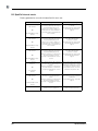
® SpotCell Viewer User Manual version 2.4 Table of Contents Introduction . . . . . . . . . . . . . . . . . . . . . . . . . . . . . . . . . . . . . . . . . . . . . . . . . . . . . .1 About this guide . . . . . . . . . . . . . . . . . . . . . . . . . . . . . . . . . . . . . . . . . . . . . . . .1 Compatibility . . . . . . . . . . . . . . . . . . . . . . . . . . . . . . . . . . . . . . . . . . . . . . . . . . .1 Getting Started . . . . . . . . . . . . . . . . . . . . . . . . . . . . . . . . . . . . . . . . . . . . . . . . . . .2 Packing List . . . . . . . . . . . . . . . . . . . . . . . . . . . . . . . . . . . . . . . . . . . . . . . . . . .2 System Requirements . . . . . . . . . . . . . . . . . . . . . . . . . . . . . . . . . . . . . . . . . . .2 Customer Provided Cable . . . . . . . . . . . . . . . . . . . . . . . . . . . . . . . . . . . . . . . . .2 Software Installation . . . . . . . . . . . . . . . . . . . . . . . . . . . . . . . . . . . . . . . . . . . . .3 Connecting to the SpotCell CU . . . . . . . . . . . . . . . . . . . . . . . . . . . . . . . . . . . . . . .4 Local connection to SpotCell system . . . . . . . . . . . . . . . . . . . . . . . . . . . . . . . .4 Remote connection to the SpotCell CU . . . . . . . . . . . . . . . . . . . . . . . . . . . . . .5 Install & Active Mode System Displays . . . . . . . . . . . . . . . . . . . . . . . . . . . . . . . . . .8 SpotCell Viewer – Install Mode . . . . . . . . . . . . . . . . . . . . . . . . . . . . . . . . . . . . .8 System Parameters . . . . . . . . . . . . . . . . . . . . . . . . . . . . . . . . . . . . . . . . . . .8 Adaptive System Parameters . . . . . . . . . . . . . . . . . . . . . . . . . . . . . . . . . . .9 SpotCell Viewer - Active Mode . . . . . . . . . . . . . . . . . . . . . . . . . . . . . . . . . . . .10 Using SpotCell Viewer . . . . . . . . . . . . . . . . . . . . . . . . . . . . . . . . . . . . . . . . . . . . .11 The Connection Tab . . . . . . . . . . . . . . . . . . . . . . . . . . . . . . . . . . . . . . . . . . . .11 Communication port . . . . . . . . . . . . . . . . . . . . . . . . . . . . . . . . . . . . . . . . .11 Dual band system selection . . . . . . . . . . . . . . . . . . . . . . . . . . . . . . . . . . . .11 Authentication . . . . . . . . . . . . . . . . . . . . . . . . . . . . . . . . . . . . . . . . . . . . . .12 Managing Accounts . . . . . . . . . . . . . . . . . . . . . . . . . . . . . . . . . . . . . . . . .12 Setting the timeout period . . . . . . . . . . . . . . . . . . . . . . . . . . . . . . . . . . . . .13 Modem Terminal . . . . . . . . . . . . . . . . . . . . . . . . . . . . . . . . . . . . . . . . . . . .13 Ending a Remote Session . . . . . . . . . . . . . . . . . . . . . . . . . . . . . . . . . . . . .13 Server Mode (stand-by condition) . . . . . . . . . . . . . . . . . . . . . . . . . . . . . . .13 The Events Tab . . . . . . . . . . . . . . . . . . . . . . . . . . . . . . . . . . . . . . . . . . . . . . .14 Logging Events . . . . . . . . . . . . . . . . . . . . . . . . . . . . . . . . . . . . . . . . . . . . .14 The Control Tab . . . . . . . . . . . . . . . . . . . . . . . . . . . . . . . . . . . . . . . . . . . . . . .15 Password protection . . . . . . . . . . . . . . . . . . . . . . . . . . . . . . . . . . . . . . . . .15 Forcing to Install mode . . . . . . . . . . . . . . . . . . . . . . . . . . . . . . . . . . . . . . .16 Enabling CU dial out . . . . . . . . . . . . . . . . . . . . . . . . . . . . . . . . . . . . . . . . .16 Disabling the Donor Unit (DU) power supply . . . . . . . . . . . . . . . . . . . . . . .16 Restarting the system . . . . . . . . . . . . . . . . . . . . . . . . . . . . . . . . . . . . . . . .16 Changing the dial out number . . . . . . . . . . . . . . . . . . . . . . . . . . . . . . . . . .16 CU identifiers . . . . . . . . . . . . . . . . . . . . . . . . . . . . . . . . . . . . . . . . . . . . . . .17 Acknowledging an alarm . . . . . . . . . . . . . . . . . . . . . . . . . . . . . . . . . . . . . .17 The Configure tab . . . . . . . . . . . . . . . . . . . . . . . . . . . . . . . . . . . . . . . . . . . . . .18 The Active Band tab . . . . . . . . . . . . . . . . . . . . . . . . . . . . . . . . . . . . . . . . . . . .18 Menu Commands . . . . . . . . . . . . . . . . . . . . . . . . . . . . . . . . . . . . . . . . . . . . . . . .19 SpotCell Events . . . . . . . . . . . . . . . . . . . . . . . . . . . . . . . . . . . . . . . . . . . . . . . . . .21 SpotCell external events . . . . . . . . . . . . . . . . . . . . . . . . . . . . . . . . . . . . . . . . .21 SpotCell internal events . . . . . . . . . . . . . . . . . . . . . . . . . . . . . . . . . . . . . . . . .22 SpotCell Viewer 2 i ii SpotCell Viewer 2 1 – Introduction SpotCell Viewer 2.4 is a PC based application that gives authorized carrier personnel remote access and control of deployed SpotCell solutions. It eliminates the need for on-site visits by carriers that use SpotCell adaptive repeaters to provide reliable, always on, in-building wireless connectivity in spaces up to 100,000 sq. ft. The SpotCell Viewer facilitates the widespread deployment of SpotCell solutions by providing carriers with real-time access to SpotCell products. Carriers can connect locally or remotely to a SpotCell, view system status, review system configuration information, log events, and if desired, save log files. 1.1 About this guide This user’s manual documents the installation and use of the SpotCell Viewer application software. 1.2 Compatibility This version of the SpotCell Viewer is compatible with the following product releases and software versions: Spotwave Wireless Inc. Product Product Release Software Version SpotCell 100 3.0 2.x.x.x SpotCell 102C 1.0 1.x.x.x SpotCell 111 3.0 2.x.x.x SpotCell 112 3.0 2.x.x.x SpotCell 141 1.0 1.x.x.x SpotCell 142 1.0 1.x.x.x SpotCell 163 1.0 1.x.x.x SpotCell 612 1.0 1.x.x.x 1 GETTING STARTED 2 – Getting Started 2.1 Packing List The SpotCell Viewer is shipped in a single box containing a: SpotCell Viewer 2.4 software CD that will be used to load the application on a customer provided computer. The User Guide is also included on the CD. 8 pin CAT 5 cable to connect the SpotCell to the customer computer. Modified RJ-45 to DB9 serial port adapter that connects the CAT 5 cable to the customer provided computer’s serial port. Quick Start guide. 2.2 System Requirements SpotCell Viewer operates on a customer provided PC based platform with the following system requirements. Windows® 2000/XP mouse, keyboard, CD-ROM drive 128 MB RAM 10 MB free space on hard drive Pentium III processor monitor (minimum 1024 x 768) free serial port modem (for remote monitor option) 2.3 Customer Provided Cable Standard 8 pin CAT 5 cables of less than 50 feet in length can be used in place of the Spotwave Wireless provided cable. 2.4 Customer Provided Adapters The provided RJ-45 to DB9 serial port adapter has been modified to operate specifically with the SpotCell Viewer. Warning! Only use the Spotwave Wireless provided adapters when connecting your computer to a SpotCell Coverage Unit. 2 SpotCell Viewer 2 GETTING STARTED 2.5 Software Installation To install SpotCell Viewer 1. Insert the SpotCell Viewer 2.4 CD-ROM into the CD-ROM drive. 2. Follow the on-screen instructions. Note: To activate the “I ACCEPT” button on the Licence Agreement window, click inside the Licence Agreement text box. The SpotCell Viewer files will be installed, by default, in the C:\Program Files\SpotCell Viewer 2.4. You can however, select a different destination folder during the installation process but all SpotCell Viewer files must remain in the SpotCell Viewer directory. SpotCell Viewer 2 3 CONNECTING TO THE SPOTCELL CU 3 – Connecting to the SpotCell CU Although the SpotCell CU displays system status on the LCD, the Viewer is useful onsite to allow a user to: Graphically display on one screen all the information available on the LCD. Monitor the SpotCell system over a period of time by logging events. Change the SpotCell mode (Active/Install) or restart the system. Setup the SpotCell configuration, identification, and dial out fields for remote monitoring 3.1 Local connection to SpotCell system To setup a connection directly (local) to the SpotCell system 1. Remove the square cover on the back of the SpotCell CU. 2. Insert one end of the CAT 5 cable into the RJ-45 jack. 3. Connect the adapter to the other end of the cable. 4. Attach the adapter to the serial port on the customer provided computer. A special USB to serial port adapter will be required to connect to laptops that are not equipped witha serial port. The computer can either be started up before or after the connection is made to the SpotCell CU. 4 SpotCell Viewer 2 CONNECTING TO THE SPOTCELL CU 3.2 Remote connection to the SpotCell CU Viewer can be used remotely to access the SpotCell CU and perform all of the same monitoring and control functions that are available with an onsite connection. The following figures illustrate two possible methods of remotely accessing and troubleshooting the SpotCell system. Figure 1.1: Remote connection using a wireline connection. Figure 1.2: Remote connection using wireless connection SpotCell Viewer 2 5 CONNECTING TO THE SPOTCELL CU To setup a connection using a wireline modem Although other modems may work, the wireline modem currently approved for use with SpotCell systems is the USRobotics USR325686E 56K V.92 External Faxmodem. Check the support page of the Spotwave Wireless web site (www.spotwave.com) for an up-to-date list of approved wireline modems. 1. Ensure the modem and CU are powered off. 2. Connect the modem and CU using an RJ-45 cable (max 50 ft.) and the provided RJ- 45 to DB25 serial adapter. 3. Before connecting power to the modem, set the DIP switches on the back of the modem as shown in the following table. 1 2 3 4 5 6 7 8 ↓ ↑ ↓ ↓ ↑ ↑ ↑ ↓ 4. Connect power to the modem first and then the CU. The CU will automatically detect and configure the modem. 5. Connect the second modem to the PC. 6. Start SpotCell Viewer by clicking: Start > Programs > SpotCell Viewer > SpotCell Viewer 2.4 7. Go to the Connection tab and ensure that the correct Comm port is selected. 8. Click Modem Terminal. 9. Configure the modem by typing in the following command string. For wireline modems type AT E1 Q0 Y0 S0=1 &B1 &D0 &H0 &I0 &K0 &M4 &N6 &U6 &R1 &W0 For wireless modems type AT+IPR=57600 ATE0 AT$QCVAD=4 AT+DS=0,0 ATS0=1 The SpotCell system is now ready for remote Viewer access and troubleshooting. 6 SpotCell Viewer 2 CONNECTING TO THE SPOTCELL CU To setup a connection using a wireless modem 1. Follow the instructions included with the SpotCell Wireless Modem Installation kit (purchased separately) for mounting and connecting the wireless modem to the CU and DU. Wireless modems currently approved for use with the SpotCell system are: - AnyData iPORT(Model: EM III Dual) - Chameleon CTM110 Wireless Modem Check the support page of the Spotwave Wireless web site (www.spotwave.com) for an up-to-date list of approved wireless modems and specific instructions for activation. 2. Follow the carrier’s instructions for activating the wireless modem. Note the phone number assigned to the wireless modem. 3. Connect the second modem to the PC. 4. Start SpotCell Viewer by clicking: Start > Programs > SpotCell Viewer > SpotCell Viewer 2.4 5. Go to the Connection tab and ensure that the correct Comm port is selected. 6. Click Modem Terminal. 7. Configure the modem by typing in the following command string. For wireline modems type AT E1 Q0 Y0 S0=1 &B1 &D0 &H0 &I0 &K0 &M4 &N6 &U6 &R1 &W0 For wireless modems type AT+IPR=57600 ATE0 AT$QCVAD=4 AT+DS=0,0 ATS0=1 The SpotCell system is ready for remote Viewer access and troubleshooting. To remotely connect to the SpotCell CU 1. Start SpotCell Viewer by clicking: Start > Programs > SpotCell Viewer > SpotCell Viewer 2.4 2. On the Connection tab, click Modem Terminal. 3. Type in the following command string to dial the remote modem. atd<phone number> (e.g. atd5674321) Where <phone number> is the number for the remote modem. 4. The remote modem will automatically answer and initiate a connection. 5. After the connection is established, end the terminal session by closing the modem terminal window. 6. The SpotCell Viewer application is now ready to communicate with the remote CU. SpotCell Viewer 2 7 INSTALL & ACTIVE MODE SYSTEM DISPLAYS 4 – Install & Active Mode System Displays Depending on whether the SpotCell system is in Install Mode or Active Mode, one of two main screens will appear when SpotCell Viewer is started. This section describes the system information displayed on these screens. 4.1 SpotCell Viewer – Install Mode 4.1.1 System Parameters System Mode 8 System mode indicates the SpotCell system is in Install by showing Install text in bold and greying out Active Mode text. Alarm indicates whether an alarm condition currently exists. Donor Unit LED provides a graphical view of the LED on the Donor Unit. System Configuration Product identifies the product that the computer is connected to. Software Version indicates which software release is installed on the unit. Band Start Frequency indicates for the SpotCell 111 & SpotCell 112 products the lowest downlink or forward path frequency of the system. This is preprogrammed at the factory. Band Stop Frequency indicates the highest downlink or forward path frequency of the system. This is pre-programmed at the factory. Bandwidth indicates the bandwidth of the Coverage Unit. SpotCell Viewer 2 INSTALL & ACTIVE MODE SYSTEM DISPLAYS Note: In the case of the SpotCell 100 unit that operates in the 800 MHz cellular band, the Start and Stop Frequencies and Bandwidth are replaced by the Cellular Band (A or B) that is pre-programmed into the unit at the factory. Coverage Unit Display Replicates the messages shown on the LCD display located on the bottom edge of the Coverage Unit. 4.1.2 Adaptive System Parameters Active Base Station Received Isotropic Power displays the level of the base-station channel selected by the adaptive algorithm. The signal level is displayed in dBm referenced to the Donor Unit antenna input. Frequency displays the base-station frequency selected by the adaptive algorithm. Current Channel Number displays the base-station channel number selected by the adaptive algorithm. Protocol displays the base-station protocol. Out of Band Signal Maximum Received Isotropic Power displays the level of the highest received out of band signal. In the case of the SpotCell 111 & SpotCell 112 the entire band outside of the start and stop frequencies is scanned and the strongest signal level indicated in this field. For the SpotCell 100, which operates in the cellular band, the unit identifies the strongest signal in the alternate band (e.g., if the unit is configured for the A band then the strongest B band signal is shown). The signal level is in dBm referenced to the Donor Unit antenna input. Frequency identifies the frequency of the highest out of band signal. Adaptive System Gains Not available when the SpotCell is in install mode. SpotCell Viewer 2 9 INSTALL & ACTIVE MODE SYSTEM DISPLAYS 4.2 SpotCell Viewer - Active Mode The SpotCell Viewer main window for a SpotCell in Active Mode is shown below. Key differences from the Install Window are: System Mode displays Active (bold) instead of Install (greyed out). Donor Unit LED information is inactive when the unit is in Active mode. 10 Adaptive System Gains parameters are active Uplink displays the current gain of the uplink in dB. Downlink displays the current gain of the downlink in dB. Isolation Back-Off displays the reduction in output (from rated 0dBm carrier @ downlink) required to prevent oscillation associated with the available isolation between the Coverage and Donor Units. SpotCell Viewer 2 USING SPOTCELL VIEWER 5 – Using SpotCell Viewer This section describes the function of SpotCell Viewer’s tabbed page interface and how to use it. 5.1 The Connection Tab The Connection tab allows you to select a communication port, authenticate a session, change passwords, manage accounts, set timeouts, and open a Modem Terminal window. 5.1.1 Communication port The port used to communicate with the Coverage Unit can be COM port 1 to COM port 24. The None option allows you to release the COM port while keeping the application running. To set the communication port 1. On the Connection tab, click Comm port. 2. In the Comm port list, click the appropriate communication port. To release the communication port On the Connection tab, click None. 5.1.2 Dual band system selection SpotCell Viewer can communicate with either the Primary or Secondary part of a SpotCell 141/142, dual band system. To select a system On the Connection tab, click either Primary or Secondary. The Primary/Secondary option is only available for the dual band system. Single band systems will display Standard, which is for reference use only and cannot be changed. SpotCell Viewer 2 11 USING SPOTCELL VIEWER 5.1.3 Authentication Login authentication is used to control user access to the SpotCell system. By default, there is one Administrator account already setup on the Spotcell system and up to 14 additional user accounts can be created. Administrative functions such as setting session time-outs or creating, editing, and deleting accounts are accessible only to the Administrator. To login (open a session for communication) 1. On the Connection tab, click Login. 2. In the Login dialog box, type your Username and Password. 3. Click Login. If a user attempts to login to an account with incorrect authentication 3 consecutive times, then the system locks out that account. The account can only be re-activated by the administrator. To logout (close a session) On the Connection tab, click Logout. 5.1.4 Managing Accounts To create a new account 1. On the Connection tab, click New Account. 2. In the Create New Account dialog box, type your Administrator Username, Administrator Password, New Username, and New Password. The Password must be a minimum of 8 characters in length, containing at least 3 of the following: a number, a special character, and a lowercase or uppercase character. The Username must be a minimum of 1 character in length and cannot match the password. 3. Click Create Account. To change a user account password 1. On the Connection tab, click Change Password. 2. In the Change Password dialog box, type the Username, Old Password, New Password, and Confirm New Password. The New Password must be a minimum of 8 characters in length, containing at least 3 of the following: a number, a special character, and a lowercase or uppercase character. The New Password cannot match the Username. 3. Click OK. To delete a user account 12 On the Connection tab, click Delete Account. SpotCell Viewer 2 USING SPOTCELL VIEWER 5.1.5 Setting the timeout period A SpotCell Viewer session will automatically timeout after a specific period of inactivity. The timeout period can only be set by the adminstrator. To set the timeout 1. On the Connection tab, click Set Timeout. 2. Type the administrator username, password, and timeout period. The timeout range is 10 seconds to 30 minutes. The default timeout period is 2 minutes. 3. Click Set Timeout. 5.1.6 Modem Terminal The modem terminal window allows the user to communicate with a modem connected to the selected COM port. To open a modem terminal window On the Connection tab, click Modem Terminal. The “atd” command followed by a phone number and the “Return” key will initiate a dial-out from the modem. The Send button has the same function as the “Return” key and the “Clear Terminal” button clears the Terminal window. Note: The modem port must be configured to “No Flow Control”. 5.1.7 Ending a Remote Session A modem hang-up request for the existing connection should always be done when ending a remote session. Failing to do so may result in the modem remaining connected to the remote unit until the PC is powered down. To send a modem hang-up On the Connection tab, click Disconnect. 5.1.8 Server Mode (stand-by condition) Enabling Server Mode sets SpotCell Viewer to a stand-by condition, waiting for a remote connection to be initiated by the SpotCell system. To set Viewer to stand-by On the Connection tab, select the Server Mode check box. If a connection is initiated and established by the system while in secure communication mode, the user may have to login to the view the data. Once a connection has been established, the Disconnect button must be used to hang up the connection. Note: SpotCell Viewer must be connected to a modem in order to receive a remote connection. SpotCell Viewer 2 13 USING SPOTCELL VIEWER 5.2 The Events Tab The Events tab allows you to view or log system events and events generated by the Coverage Unit’s adaptive algorithm. For a list and description of SpotCell log events see SpotCell Events on page 21. To clear the view window On the Events tab, click Clear. 5.2.1 Logging Events The Events tab view window limit is 1000 events and once this is reached, the oldest messages are lost as new events are displayed. Logging events to a file on your PC will avoid this limitation. To log events to a file on your PC Note: To prevent loss of data, you should rename the previous log file before enabling “Log to file”. 1. On the Events tab, click the Browse button. 2. Select a filename and location where the events are to be logged. 3. Select the “Log to file” check box. This clears the contents of the log file. Any new events will now be logged to the file. To stop logging events on your PC 14 On the Events tab, clear the Log to file check box. SpotCell Viewer 2 USING SPOTCELL VIEWER 5.3 The Control Tab The Control tab allows you to: force the SpotCell system to Install mode disable/enable dial out mode or the DU power supply restart the system from a known good state change Alarm phone numbers and Unit ID fields change the password (25 printable characters/case sensitive) 5.3.1 Password protection All functions of the Control tab require a password to be entered before the command can be completed. The password is encrypted to ensure security during remote access to the CU. The initial password at installation is “spotcell”. To change the password 1. On the Control tab, click Change Password. 2. Type the old password and new password. The password can contain up to 25 printable characters and is case sensitive. 3. Confirm the new password by typing it again in the Confirm New Password field and click OK. SpotCell Viewer 2 15 USING SPOTCELL VIEWER 5.3.2 Forcing to Install mode When the SpotCell is in auto mode (normal operating mode), setting the system to install or active is controlled with the mode switch on the Coverage Unit (CU). Using Viewer, the SpotCell system can be forced to install mode by simply disabling auto mode. To force the system to Install Mode On the Control tab, clear the AUTO check box. Selecting the AUTO check box will return the system to auto mode (normal operating mode). 5.3.3 Enabling CU dial out The SpotCell can be setup to automatically dial out to a remote monitoring site when an alarm condition is created. To enable Dial Out Mode On the Control tab, select the CU Dial Out Enabled check box. Enabling CU Dial Out sends the atdsø string to the modem. 5.3.4 Disabling the Donor Unit (DU) power supply The RF output from the DU can be shut down by disabling the DU power supply. To disable the DU power supply On the Control tab, clear the DU ON check box Note: Do not disable the power supply when the DU is connected to a remote wireless modem. Disabling the power to the DU will also disable the remote wireless modem connection. Selecting the DU ON check box will re-enable the DU power supply. 5.3.5 Restarting the system Restarting the SpotCell unit is the easiest way to reset the system to the last known good state. To restart the system 1. On the Control tab, click Restart Unit. 2. Type the password and click OK. The SpotCell system will restart from a known good state. 5.3.6 Changing the dial out number If CU dial out is enabled, then the system will automatically dial out to a remote monitoring site when an alarm condition is created. The phone number the CU dials is entered through the Alarm Phone Number dialog box. 16 SpotCell Viewer 2 USING SPOTCELL VIEWER To change the CU dial out number 1. On the Control tab, click Change Alarm Phone Number. 2. Type the new phone number. 5.3.7 CU identifiers Each SpotCell system has two field IDs that help identify the unit when connecting to a remote monitoring site. To change the CU Identifiers 1. On the Control tab, click Change Unit ID Field #1 or Change Unit ID Field #2. 2. Type any appropriate identifying text (up to 32 printable characters) in the New Identification field. 3. Click OK to accept the Unit ID change. 5.3.8 Acknowledging an alarm If CU dial out is enabled, then the system will automatically dial out to a remote monitoring site when an alarm condition is created. If the alarm condition still exists after hanging up, then the CU will repeatedly dial out with the same alarm information. Acknowledging the alarm will prevent the CU from dialing out until the alarm clears and another alarm is generated. To acknowledge an alarm On the Control tab, click Alarm Acknowledged. After hanging up, the CU will not attempt to dial out (if enabled) until the alarm clears and another alarm occurs. SpotCell Viewer 2 17 USING SPOTCELL VIEWER 5.4 The Configure tab The Configure tab is only available when connected to the SpotCell 163 or SpotCell 263 product. The Configure tab is used to view or modify the prefered channels and to force the system to use the preferred channels for scanning. To program the preferred channels 1. On the Configure tab, click Modify. 2. Set the preffered channels, and click OK. To use preferred channels for scanning On the Configure tab, select the Enable Exclusive Channel List check box. 5.5 The Active Band tab The Active Band tab is only available when connected to SpotCell systems designed for the PCS band (SpotCell 111/112, SpotCell 211/212, or SpotCell 141/142) . The Active Band tab is used to set the start and stop frequency of the SpotCell device. To set the start and stop frequencies 1. On the Active Band tab, enter the Band Start or Band Stop Frequency. The bandwidth is fixed, so adjusting either frequency will affect both values. 2. Click Set Frequency. 3. Type your username and pasword to authenticate the frequency change and click OK. 18 SpotCell Viewer 2 Appendix A – Menu Commands A.1 File Menu A.1.1 Exit command To exit the SpotCell Viewer application Click on the File drop-down menu and select Exit. A.2 Help Menu The Help drop-down menu contains the Help and About SpotCell Viewer command. A.2.1 Help command Each item in the main window has an associated help file topic. To view the Help file, click on the Help drop-down menu and select Help. To obtain details about a SpotCell Viewer parameter, click on the desired parameter. A.2.2 About command The About command displays the About Window, which shows the software version or release number. SpotCell Viewer 19 20 SpotCell Viewer 2 Appendix B – SpotCell Events B.1 SpotCell external events Events generated from external inputs to the SpotCell product are: Event Description Troubleshooting Active Signal Undetectable: Searching The active base station signal is not present. The adaptive algorithm is searching for an inband signal. Coverage is not provided during this period. When an Active Signal is found, the event notification is cleared. Coverage is provided after the event is cleared. Realign the DU. Refer to the SpotCell User's Manual for additional information. The active base station signal is too strong. All inband signals must be equal to or lower than the maximum rated input signal level. The adaptive algorithm is searching the inband spectrum. Coverage is not provided during this period. When all inband signals are within the desired range, the event notification is cleared. Coverage is provided after the event is cleared. Realign the DU. Refer to the SpotCell User's Manual for additional information. The active base station signal is detected but is too weak. The adaptive algorithm is searching for an inband signal that meets or exceeds the minimum rated input signal level. Coverage is not provided during this period. When an Active Signal is found, the event notification is cleared. Coverage is provided after the event is cleared. Realign the DU. Refer to the SpotCell User's Manual for additional information. The out-of-band signal is too strong. All out-of-band signals must be equal to or lower than the maximum rated input signal level. The adaptive algorithm is searching the out-of-band spectrum. Coverage is not provided during this period. When all out-of-band signals are within the desired range, the event notification is cleared. Coverage is provided after the event is cleared. Realign the DU. Refer to the SpotCell User's Manual for additional information. A stronger active base station signal has been selected by the adaptive algorithm. No user action is required. OR Active Signal Undetectable: Cleared Active Signal Overdrive: Searching OR Active Signal Overdrive: Cleared Active Signal Too Low Searching OR Active Signal Too Low: Cleared Out-of-band Signal Overdrive: Searching OR Out-of-band Signal Overdrive: Cleared Selected Stronger Active Signal SpotCell Viewer 21 B.2 SpotCell internal events Events generated as a result of internal built-in-tests are: Event Description Troubleshooting CU Voltage Out-of-range: Out of Service The CU power supply voltage is outside the rated operating range. Coverage is not provided during this period. When the out-of-range condition is no longer present, the event notification is cleared. Coverage is provided after the event is cleared. Check the power supply connection to the CU. If the problem persists, remove power from the CU and call product support. The DU current consumption is outside the rated operating range. Coverage is not provided during this period. When the out-of-range condition is no longer present, the event notification is cleared. Coverage is provided after the event is cleared. Check the power supply connection to the CU and the RF cable connection to the DU. If the problem persists, remove power from the CU and call product support. The DU power supply voltage is outside the rated operating range. Coverage is not provided during this period. When the condition is no longer present, the event notification is cleared. Coverage is provided after the event is cleared. Check the power supply connection to the CU and the RF cable connection to the DU. If the problem persists, remove power from the CU and call product support. The isolation between the DU and the CU is low. Coverage is degraded during this period. When the condition is no longer present, the event notification is cleared. Full coverage is provided after the event is cleared. Move the CU away from the DU and observe the Isolation bars on the CU LCD display. A minimum of four bars are required for adequate isolation. If the problem persists, relocate the DU further away from the CU. The synthesizer is being retuned. Coverage is not provided during this period. When the condition is no longer present, the event notification is cleared. Coverage is provided after the event is cleared. A period of ten minutes is required to retune and reassess the operation of a synthesizer. If the problem persists, call product support. Available isolation is inadequate for the system to become operational. Increase the separation/isolation between the CU and the DU. OR CU Voltage Out-of-range: Cleared DU Current Out-of-range: Out of Service OR DU Current Out-of-range: Cleared DU Voltage Out-of-range: Out of Service OR DU Voltage Out-of-range: Cleared Poor Isolation: Move CU OR Poor Isolation: Cleared Synthesizer Out-of-lock: Out of Service OR Synthesizer Out-of-lock: Cleared Insufficient Isolation 22 SpotCell Viewer 2 www.spotwave.com Spotwave Wireless Inc. 1 Hines Road, Ottawa ON K2K 3C7 Canada © 2005 Spotwave Wireless Inc. All rights reserved. Printed in Canada Spotwave and SpotCell are trademarks of Spotwave Wireless Inc. Patents pending.