1
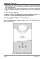
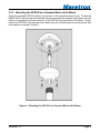
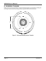
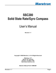
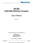
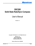
®
GPS100
GPS/WAAS Antenna/Receiver
User’s Manual
Revision 1.2
Copyright © 2005 Maretron, LLC All Rights Reserved
Maretron, LLC
9034 N. 23rd Ave #13
Phoenix, AZ 85021-7850
http://www.maretron.com
Maretron Manual Part #: M000301
Revision 1.2
Page i
GPS100 User’s Manual
Revision History
Revision
Description
1.0
Original document.
1.1
Minor editorial changes.
Added description of variation output in several locations.
1.2
Added reference to GPS100 firmware release (1.1)
Added references for disabling periodic rate (3.0, Appendix A)
Page ii
Revision 1.2
®
Table of Contents
1
2
3
4
5
6
7
8
9
Introduction ....................................................................................................................... 1
1.1 Firmware Revision.................................................................................................... 1
1.2 GPS100 Features..................................................................................................... 1
Installation......................................................................................................................... 1
2.1 Unpacking the Box ................................................................................................... 1
2.2 Choosing a Mounting Location ................................................................................. 1
2.3 Mounting the GPS100 .............................................................................................. 2
2.3.1 Mounting the GPS100 to a Horizontal Surface .............................................. 2
2.3.2 Mounting the GPS100 to a Standard Marine Pole Mount .............................. 3
2.4 Connecting the GPS100........................................................................................... 4
2.4.1 Checking Connections................................................................................... 5
Operation .......................................................................................................................... 5
3.1 Magnetic Variation.................................................................................................... 5
Maintenance ..................................................................................................................... 6
Troubleshooting ................................................................................................................ 7
Technical Specifications.................................................................................................... 7
Technical Support ............................................................................................................. 9
Installation Template ....................................................................................................... 10
Maretron (2 Year) Limited Warranty................................................................................ 11
Table of Figures
Figure 1 – Mounting the GPS100 to a flat surface..................................................................... 2
Figure 2 – Mounting the GPS100 to a Standard Marine Pole Mount......................................... 3
Figure 3 – GPS100 Interface Connector.................................................................................... 4
Figure 4 – NMEA 2000® Connector Face Views ....................................................................... 4
Figure 5 – Horizontal Mounting Surface Template .................................................................. 10
Table of Appendices
Appendix A – NMEA 2000 Interfacing ..................................................................................... A1
Revision 1.2
Page iii
GPS100 User’s Manual
This page intentionally left blank.
Page iv
Revision 1.2
®
1 Introduction
Congratulations on your purchase of the Maretron GPS100 GPS/WAAS Antenna/Receiver.
Maretron has designed and built your GPS100 to the highest standards for years of reliable,
dependable, and accurate service.
The Maretron GPS100 is designed to operate within the harsh demands of the marine
environment. However, no piece of marine electronic equipment can function properly unless
installed and maintained in the correct manner. Please read carefully and follow these
instructions for installation and usage of the Maretron GPS100 in order to ensure optimal
performance.
1.1 Firmware Revision
This manual corresponds to GPS100 firmware revision 1.5.
1.2 GPS100 Features
The Maretron GPS100 has the following features.
•
•
•
•
•
•
NMEA 2000® Interface
12 Channel GPS Antenna/Receiver
Satellite Based Augmentation System (SBAS) capable (WAAS, EGNOS and MSAS)
Accurate Location, COG and SOG Data to Any NMEA 2000® Device Including Chart
Plotters, Autopilots, and Instrumentation Displays
Magnetic Variation Output Based on World Magnetic Model (WMM2005)
Waterproof Enclosure and Cable System
2 Installation
2.1 Unpacking the Box
When unpacking the box containing the Maretron GPS100, you should find the following items:
1 - GPS100 GPS/WAAS Antenna/Receiver
1 - Pole Mount Base
3 - Mounting Screws and Lock Washers
1 - GPS100 User’s Manual
1 - Warranty Registration Card
If any of these items are missing or damaged, please contact Maretron.
2.2 Choosing a Mounting Location
The selection of a suitable mounting location is important for the optimal performance of the
Maretron GPS100. The mounting location and orientation of the GPS100 should be:
1. Level with the earth’s horizontal plane – This gives the GPS100 antenna the optimal view
of satellites from all directions.
Revision 1.2
Page 1
GPS100 User’s Manual
2. High Enough to have a clear view of the sky to the horizon in all directions unblocked by
masts or antennas – The GPS100 provides the best readings when it has access to as
many satellites as possible.
3. As far as possible from VHF, satellite, or radar antennas – Radio frequency transmissions
from these antennas can interfere with the proper reception of GPS satellite signals by the
GPS100.
2.3 Mounting the GPS100
The Maretron GPS100 can be mounted directly on top of a horizontal surface (Section 2.3.1)
or on top of a 1” 14 threads per inch standard marine pole mount (Section 2.3.2).
2.3.1
Mounting the GPS100 to a Horizontal Surface
Attach the GPS100 securely to the vessel using the included brass mounting screws and
included lock washers or other fasteners as shown in Figure 1 (see mounting template in
Section 8 for drill pattern).
Figure 1 – Mounting the GPS100 to a flat surface
Page 2
Revision 1.2
®
2.3.2 Mounting the GPS100 to a Standard Marine Pole Mount
Screw the included GPS100 antenna mount base to the standard marine mount. Thread the
NMEA 2000® cable through the standard marine mount and the antenna mount base from the
bottom out through the top and connect it to the GPS100 unit (see Section 2.4 below). Finally,
attach the GPS100 to the antenna mount base using the included brass mounting screws and
lock washers as shown in Figure 2.
Figure 2 – Mounting the GPS100 to a Standard Marine Pole Mount
Revision 1.2
Page 3
GPS100 User’s Manual
2.4 Connecting the GPS100
The Maretron GPS100 provides a connection to an NMEA 2000® interface through a
connector that can be found on the bottom of the device (see Figure 3).
®
NMEA 2000 Connector
Figure 3 – GPS100 Interface Connector
The NMEA 2000® connector is a five pin male connector (see Figure 4). You connect the
GPS100 to an NMEA 2000® network using a Maretron NMEA 2000® cable (or compatible
cable) by connecting the female end of the cable to the GPS100 (note the key on the male
connector and keyway on the female connector). Be sure the cable is connected securely and
that the collar on the cable connector is tightened firmly. Connect the other end of the cable
(male) to the NMEA 2000® network in the same manner. The GPS100 is designed such that
you can plug or unplug it from an NMEA 2000® network while the power to the network is
connected or disconnected. Please follow recommended practices for installing NMEA 2000®
network products.
Figure 4 – NMEA 2000® Connector Face Views
Page 4
Revision 1.2
®
2.4.1 Checking Connections
Once the NMEA 2000® connection to the Maretron GPS100 has been completed, check to see
that heading information is being properly transmitted by observing an appropriate display.
Refer to Section 5, “Troubleshooting”, if no heading information appears.
3 Operation
As shipped from the factory, the GPS100 automatically provides position, time, SOG, COG,
magnetic variation, and satellite information and requires no user configuration. However,
some of the GPS100 parameters are user configurable as described below:
•
•
•
•
•
•
•
Desired Operating Mode – the GPS100 may be programmed to operate in 2D mode, 3D
mode, or the best available operating mode (factory default)
SBAS (WAAS) – the GPS100 may be programmed to use SBAS (WAAS) using the best
available SBAS satellite (factory default). A specific SBAS satellite may be specified, or
SBAS may be disabled altogether.
SV Elevation Mask – as shipped from the factory, the GPS100 uses all visible satellites
in its position solution, regardless of the elevation (angle above the horizon). A user
may specify a SV Elevation Mask, such that only satellites with an elevation greater
than this value will be used in the position solution.
PDOP Mask – as shipped from the factory, the GPS100 will report a GPS fix whenever
possible, regardless of the value of position dilution of precision (PDOP). A user may
specify a PDOP Mask, such that whenever the PDOP is above the specified value, the
GPS100 will report that no GPS fix is available.
SNR Mask – As shipped from the factory, the GPS100 will use all detectable satellites
in its position solution, regardless of the signal-to-noise ratio (SNR). A user may specify
a SNR mask, such that such that only satellites with an SNR greater than this value will
be used in the position solution.
Antenna Altitude – A user may specify an antenna altitude for use when the GPS100 is
operating in 2D mode. As shipped from the factory, the GPS100 will use the altitude
calculated when it was last operating in 3D mode.
Periodic Rate of Transmission – As shipped from the factory, the GPS100 transmits
PGNs at a periodic rate. Alternatively, a PGN can be disabled by programming its
periodic rate to zero.
These parameters may be configured using a Maretron instrumentation display, such as the
Maretron DSM200, or other NMEA 2000® chartplotters or instrumentation displays with GPS
configuration capability. Please refer to your chartplotter/display manual for details.
Users with direct access to the NMEA 2000® interface may configure these parameters directly
through the NMEA 2000® interface. Please refer to Appendix A for a description of the NMEA
2000® messages used to configure these parameters.
3.1 Magnetic Variation
Magnetic variation is the angular difference between the true meridian (great circle connecting
the geographic poles) and the magnetic meridian (direction of the lines of magnetic flux).
Revision 1.2
Page 5
GPS100 User’s Manual
Magnetic variation has different values at different locations on the earth with most areas
undergoing change to the magnetic variation over time.
The GPS100 indicates magnetic variation anywhere on Earth using the World Magnetic Model
(WWM2005). It is important to understand that the WMM2005 geomagnetic model only
characterizes that portion of the Earth’s magnetic field that is generated in the Earth’s fluid
outer core (the main magnetic field). The portions of the geomagnetic field generated by the
Earth’s crust and upper mantle, and by the ionosphere and magnetosphere, are not
represented in the WMM2005. Consequently, a magnetic sensor such as a compass or
magnetometer may observe spatial and temporal magnetic anomalies when referenced to the
WMM2005. In particular, certain local, regional, and temporal magnetic declination anomalies
can exceed 10 degrees. Anomalies of this magnitude are not common but they do exist.
Declination anomalies of the order of 3 or 4 degrees are not uncommon but are of small spatial
extent and are relatively isolated.
On land, spatial anomalies are produced by mountain ranges, ore deposits, ground struck by
lightning, geological faults, and cultural features such as trains, planes, tanks, railroad tracks,
power lines, etc. The corresponding deviations are usually smaller at sea, and decrease with
increasing altitude of an aircraft or spacecraft. In ocean areas, these anomalies occur most
frequently along continental margins, near seamounts, and near ocean ridges, trenches, and
fault zones, particularly those of volcanic origin. Ships and submarines are also sources of
magnetic anomalies in the ocean.
However, from a global main field perspective, the declination (D), inclination (I), and grid
variation (GV) RMS errors of WMM2005 are estimated to be less than 1.0° at the Earth’s
surface over the entire 5-year life span of the model. Also, the RMS errors at the Earth’s
surface horizontal intensity (H), the vertical component (Z), and the total intensity (F) of
WMM2005 are estimated to be well below 200 nT over the entire 5-year life of the model.
Thus, the WMM2005 meets and exceeds the accuracy requirements detailed in MIL-W-89500
(Defense Mapping Agency, 1993) for the entire life span of the model. To learn more about the
WWM2005, please visit http://www.ngdc.noaa.gov/seg/WMM/DoDWMM.shtml.
4 Maintenance
Regular maintenance is important to ensure continued proper operation of the Maretron
GPS100. Perform the following tasks periodically:
•
•
•
Clean the unit with a soft cloth. Do not use chemical cleaners as they may remove
paint or markings or may corrode the GPS100 enclosure or seals.
Ensure that the unit is mounted securely and cannot be moved relative to the mounting
surface. If the unit is loose, tighten the mounting screws.
Check the security of the cable connected to the NMEA 2000® interface and tighten if
necessary.
Page 6
Revision 1.2
®
5 Troubleshooting
If you notice unexpected operation of the Maretron GPS100, follow the troubleshooting
procedures in this section to remedy simple problems.
Symptom
No data output
Troubleshooting Procedure
Check the connections to the NMEA
2000® connector and tighten if
necessary
Ensure that power is supplied to the
connected NMEA 2000® cable
Ensure that the GPS100 has a clear
view to the horizon in all directions
Ensure that no VHF, satellite, or radar
antennas have been mounted near the
GPS100
If these steps do not solve your problem, please contact Maretron Technical Support (refer to
Section 7 for contact information).
Warning: There are no user-serviceable components inside the Maretron GPS100. Opening
the GPS100 will expose the sensitive electronic components to adverse environmental
conditions that may render the unit inoperative. Please do not open the GPS100, as this will
automatically void the warranty. If service is required, please return the unit to an authorized
Maretron service location.
6 Technical Specifications
Specifications
Parameter
Position Accuracy (Autonomous)
Position Accuracy (WAAS)
Channels
Position Update Rate
Speed Update Rate
Time Update Rate
Hot Start
Warm Start
Cold Start
Satellite Based Augmentation
System
Battery Backup
Revision 1.2
Value
<10m
< 3m
12
10 per Second
4 per Second
1 per Second
8 Seconds
38 Seconds
45 Seconds
WAAS
EGNOS
MSAS
Lithium (4-5 Days)
Comment
2D RMS (95% of Data Falls Within 10m)
2D RMS (95% of Data Falls Within 3m)
Simultaneous Tracking of 12 Satellites
Start Within Hours of Last Power Down
Start Within Days of Last Power Down
Start from Unknown Position
North America
Europe
Asia
Holds Position for Hot/Warm Starts
Page 7
GPS100 User’s Manual
Certifications
Parameter
NMEA 2000
Maritime Navigation and Radiocommunication Equipment & Systems
FCC and CE Mark
Comment
Level A
Tested to IEC 60945
Electromagnetic Compatibility
NMEA 2000® Parameter Group Numbers (PGNs) - See Appendix A for Details
Description
Periodic Data PGNs
Response to Requested PGNs
Protocol PGNs
PGN #
126992
128259
129025
129026
129029
129539
129540
127258
126464
126996
126998
129538
129541
059392
059904
060416
060160
060928
065240
126206
PGN Name
System Time
Speed
Position, Rapid Update
COG and SOG, Rapid Update
GNSS Position Data
GNSS DOPs
GNSS Satellites in View
Magnetic Variation
PGN List (Transmit and Receive)
Product Information
Configuration Information
GNSS Control Status
GPS Almanac Data
ISO Acknowledge
ISO Request
ISO Transport Protocol, Connection
Management
ISO Transport Protocol, Data Transfer
ISO Address Claim
ISO Address Command
NMEA
Default Rate
1 Time/Second
Disabled
10 Times/Second
4 Times/Second
1 Time/Second
1 Time/Second
1 Time/Second
1 Time/Second
N/A
N/A
N/A
N/A
N/A
N/A
N/A
N/A
N/A
N/A
N/A
N/A
Electrical
Parameter
Operating Voltage
Power Consumption
Load Equivalence Number (LEN)
Reverse Battery Protection
Load Dump Protection
Value
9 to 16 Volts
<150mA
3
Yes
Yes
Comment
DC Voltage
Average Current Drain
®
NMEA 2000 Spec. (1LEN = 50 mA)
Indefinitely
Energy Rated per SAE J1113
Mechanical
Parameter
Size
Weight
Mounting
Page 8
Value
4” Diameter x 1.65” Tall
6 oz.
Deck or Pole
Comment
Not Including Antenna Mount Base
Not Including Antenna Mount Base
Revision 1.2
®
Environmental
Parameter
IEC 60954 Classification
Degree of Protection
Operating Temperature
Storage Temperature
Relative Humidity
Vibration
Rain and Spray
Solar Radiation
Corrosion (Salt Mist)
Electromagnet Emission
Electromagnetic Immunity
Safety Precautions
Value
Exposed
IP67
-25°C to 55°C
-40°C to 70°C
93%RH @40° per IEC60945-8.2
2-13.2Hz @ ±1mm, 13.2-100Hz @ 7m/s2 per IEC 60945-8.7
12.5mm Nozzle @ 100liters/min from 3m for 30min per IEC 60945-8.8
Ultraviolet B, A, Visible, and Infrared per IEC 60945-8.10
4 times 7days @ 40°C, 95%RH after 2 hour Salt Spray Per IEC 60945-8.12
Conducted and Radiated Emission per IEC 60945-9
Conducted, Radiated, Supply, and ESD per IEC 60945-10
Dangerous Voltage, Electromagnetic Radio Frequency per IEC 60945-12
7 Technical Support
If you require technical support for Maretron products, you can reach us in one of the following
ways:
Telephone:
Fax:
E-mail:
World Wide Web:
Mail:
Revision 1.2
1-866-550-9100
1-602-861-1777
[email protected]
http://www.maretron.com
Maretron, LLC
Attn: Technical Support
9034 N. 23rd Ave Suite 13
Phoenix, AZ 85021 USA
Page 9
GPS100 User’s Manual
8 Installation Template
Please check the dimensions before using the following diagram as a template for drilling the
mounting holes because the printing process may have distorted the dimensions.
2.11”
Figure 5 – Horizontal Mounting Surface Template
Page 10
Revision 1.2
®
9 Maretron (2 Year) Limited Warranty
Maretron warrants the GPS100 to be free from defects in materials and workmanship for two (2) years from the
date of original purchase. If within the applicable period any such products shall be proved to Maretron’s
satisfaction to fail to meet the above limited warranty, such products shall be repaired or replaced at Maretron’s
option. Purchaser's exclusive remedy and Maretron’s sole obligation hereunder, provided product is returned
pursuant to the return requirements below, shall be limited to the repair or replacement, at Maretron’s option, of
any product not meeting the above limited warranty and which is returned to Maretron; or if Maretron is unable to
deliver a replacement that is free from defects in materials or workmanship, Purchaser’s payment for such
product will be refunded. Maretron assumes no liability whatsoever for expenses of removing any defective
product or part or for installing the repaired product or part or a replacement therefore or for any loss or damage
to equipment in connection with which Maretron’s products or parts shall be used. With respect to products not
manufactured by Maretron, Maretron’s warranty obligation shall in all respects conform to and be limited to the
warranty actually extended to Maretron by its supplier. The foregoing warranties shall not apply with respect to
products subjected to negligence, misuse, misapplication, accident, damages by circumstances beyond
Maretron’s control, to improper installation, operation, maintenance, or storage, or to other than normal use or
service.
THE FOREGOING WARRANTIES ARE EXPRESSLY IN LIEU OF AND EXCLUDES ALL OTHER EXPRESS OR
IMPLIED WARRANTIES, INCLUDING BUT NOT LIMITED TO THE IMPLIED WARRANTIES OF
MERCHANTABILITY AND OF FITNESS FOR A PARTICULAR PURPOSE.
Statements made by any person, including representatives of Maretron, which are inconsistent or in conflict with
the terms of this Limited Warranty, shall not be binding upon Maretron unless reduced to writing and approved by
an officer of Maretron.
IN NO CASE WILL MARETRON BE LIABLE FOR INCIDENTAL OR CONSEQUENTIAL DAMAGES, DAMAGES
FOR LOSS OF USE, LOSS OF ANTICIPATED PROFITS OR SAVINGS, OR ANY OTHER LOSS INCURRED
BECAUSE OF INTERRUPTION OF SERVICE. IN NO EVENT SHALL MARETRON’S AGGREGATE LIABILITY
EXCEED THE PURCHASE PRICE OF THE PRODUCT(S) INVOLVED. MARETRON SHALL NOT BE SUBJECT
TO ANY OTHER OBLIGATIONS OR LIABILITIES, WHETHER ARISING OUT OF BREACH OF CONTRACT OR
WARRANTY, TORT (INCLUDING NEGLIGENCE), OR OTHER THEORIES OF LAW WITH RESPECT TO
PRODUCTS SOLD OR SERVICES RENDERED BY MARETRON, OR ANY UNDERTAKINGS, ACTS OR
OMISSIONS RELATING THERETO.
Maretron does not warrant that the functions contained in any software programs or products will meet
purchaser’s requirements or that the operation of the software programs or products will be uninterrupted or error
free. Purchaser assumes responsibility for the selection of the software programs or products to achieve the
intended results, and for the installation, use and results obtained from said programs or products. No
specifications, samples, descriptions, or illustrations provided Maretron to Purchaser, whether directly, in trade
literature, brochures or other documentation shall be construed as warranties of any kind, and any failure to conform
with such specifications, samples, descriptions, or illustrations shall not constitute any breach of Maretron’s limited
warranty.
Warranty Return Procedure:
To apply for warranty claims, contact Maretron or one of its dealers to describe the problem and determine the
appropriate course of action. If a return is necessary, place the product in its original packaging together with
proof of purchase and send to an Authorized Maretron Service Location. You are responsible for all shipping and
insurance charges. Maretron will return the replaced or repaired product with all shipping and handling prepaid
except for requests requiring expedited shipping (i.e. overnight shipments). Failure to follow this warranty return
procedure could result in the product’s warranty becoming null and void.
Maretron reserves the right to modify or replace, at its sole discretion, without prior notification, the warranty listed
above. To obtain a copy of the then current warranty policy, please go to the following web page:
http://www.maretron.com/company/warranty.php
Revision 1.2
Page 11
GPS100 User’s Manual
This Page Intentionally Left Blank
Page 12
Revision 1.2
®
Appendix A – NMEA 2000® Interfacing
GPS100 NMEA 2000® Periodic Data Transmitted PGNs
PGN 126992 – System Time
The GPS100 uses this PGN to provide a regular transmission of UTC time and date and to
provide synchronism for measurement data. The factory default for periodic transmission rate
is once per second. The transmission of this PGN can be disabled (see PGN 126208 – NMEA
Request Group Function – Transmission Periodic Rate).
Field 1: SID – The sequence identifier field is used to tie related PGNs together. For
example, the GPS100 will transmit identical SIDs for 126992 (System Time), 128259
(Speed), 129026 (COG and SOG, Rapid Update), 129029 (GNSS Position Data),
129539 (GNSS DOPs), and 129540 (GNSS Satellites in View) to indicate that the
readings are linked together (i.e., the data from each PGN was taken at the same
time although they are reported at slightly different times).
2: Source – This field is used to indicate the type of time source, therefore this field
always reads as 0 (GPS).
3: Reserved (4 bits) – This field is reserved by NMEA; therefore, this field always
contains a value of 0xF (the GPS100 sets all reserved bits to a logic 1)
4: Date – This field is used to indicate the UTC Date in resolution of 1 day (the number
of days since January 1, 1970).
5: Time – This field is used to indicate the UTC Time in resolution of 1x10⁻⁴ s (24 hour
clock, 0.0000 = midnight).
PGN 127258 – Magnetic Variation
The GPS100 uses this PGN to provide a regular transmission of magnetic variation. The
factory default for periodic transmission rate is once per second. The transmission of this PGN
can be disabled (see PGN 126208 – NMEA Request Group Function – Transmission Periodic
Rate).
Field 1: SID – The sequence identifier field is used to tie related PGNs together. For
example, the GPS100 will transmit identical SIDs for 126992 (System Time), 128259
(Speed), 129026 (COG and SOG, Rapid Update), 129029 (GNSS Position Data),
129539 (GNSS DOPs), and 129540 (GNSS Satellites in View) to indicate that the
readings are linked together (i.e., the data from each PGN was taken at the same
time although they are reported at slightly different times).
2: Variation Source – The GPS100 uses the WMM2005 for variation, therefore this field
always reads as 5 (WMM2005).
3: Reserved (4 bits) – This field is reserved by NMEA; therefore, this field always
contains a value of 0xF (the GPS100 sets all reserved bits to a logic 1)
4: Age of Service (Date) – This field is used to indicate the UTC Date in resolution of 1
day (the number of days since January 1, 1970).
5: Variation – This field is used to indicate the magnetic variation where positive values
represent Easterly and negative values represent Westerly variation.
PGN 128259 – Speed
The GPS100 uses this PGN to provide a regular transmission that describes the motion of a
vessel. The factory default for periodic transmission rate is disabled. The PGN can be
Revision 1.2
Appendix A – NMEA 2000® Interfacing
Page A1
GPS100 User’s Manual
transmitted at a periodic rate of once per second (see PGN 126208 – NMEA Request Group
Function – Transmission Periodic Rate).
Field 1: SID – The sequence identifier field is used to tie related PGNs together. For
example, the GPS100 will transmit identical SIDs for 126992 (System Time), 128259
(Speed), 129026 (COG and SOG, Rapid Update), 129029 (GNSS Position Data),
129539 (GNSS DOPs), and 129540 (GNSS Satellitess in View) to indicate that the
readings are linked together (i.e., the data from each PGN was taken at the same
time although they are reported at slightly different times).
2: Speed Water Referenced – Since the GPS100 does not provide this data, this field
always reads as 0xFFFF (data not available).
3: Speed Ground Referenced – This field is used to indicate the speed over ground
(SOG) in resolution of 1x10⁻² m/s.
4: Reserved (24 bits) – This field is reserved by NMEA; therefore, this field always
contains a value of 0xFFFFFF (the GPS100 sets all reserved bits to a logic 1)
PGN 129025 – Position, Rapid Update
The GPS100 uses this PGN to provide latitude and longitude referenced to WGS84. The
factory default for periodic transmission rate is 10 times per second. The transmission of this
PGN can be disabled (see PGN 126208 – NMEA Request Group Function – Transmission
Periodic Rate).
Field 1: Latitude – Latitude in 1x10⁻⁷ degrees ("-" = south, “+” = north)
2: Longitude – Longitude in 1x10⁻⁷ degrees ("-" = west, “+” = east)
PGN 129026 – COG and SOG, Rapid Update
The GPS100 uses this PGN to provide Course Over Ground (COG) and Speed Over Ground
(SOG). The factory default for periodic transmission rate is four times per second. The
transmission of this PGN can be disabled (see PGN 126208 – NMEA Request Group Function
– Transmission Periodic Rate).
Field 1: SID – The sequence identifier field is used to tie related PGNs together. For
example, the GPS100 will transmit identical SIDs for 126992 (System Time), 128259
(Speed), 129026 (COG and SOG, Rapid Update), 129029 (GNSS Position Data),
129539 (GNSS DOPs), and 129540 (GNSS Satellites in View) to indicate that the
readings are linked together (i.e., the data from each PGN was taken at the same
time although they are reported at slightly different times).
2: COG Reference – This field is used to indicate the direction reference of the course
over ground. This field always reads as 0 (True, not magnetic).
3: Reserved (6 bits) – This field is reserved by NMEA; therefore, this field always
contains a value of 0x3F (the GPS100 sets all reserved bits to a logic 1)
4: Course Over Ground – This field is used to indicate the course over ground (COG)
in resolution of 1x10⁻⁴ radians.
5: Speed Over Ground – This field is used to indicate the speed over ground (SOG) in
resolution of 1x10⁻² m/s.
6: Reserved (16 bits) – This field is reserved by NMEA; therefore, this field always
contains a value of 0xFFFF (the GPS100 sets all reserved bits to a logic 1)
Page A2
Appendix A – NMEA 2000® Interfacing
Revision 1.2
®
PGN 129029 – GNSS Position Data
The GPS100 uses this PGN to convey a comprehensive set of Global Navigation Satellite
System (GNSS) parameters, including position information. The factory default for periodic
transmission rate is once per second. The transmission of this PGN can be disabled (see PGN
126208 – NMEA Request Group Function – Transmission Periodic Rate).
Field 1: SID – The sequence identifier field is used to tie related PGNs together. For
example, the GPS100 will transmit identical SIDs for 126992 (System Time), 128259
(Speed), 129026 (COG and SOG, Rapid Update), 129029 (GNSS Position Data),
129539 (GNSS DOPs), and 129540 (GNSS Satellites in View) to indicate that the
readings are linked together (i.e., the data from each PGN was taken at the same
time although they are reported at slightly different times).
2: Position date –UTC Date in resolution of 1 day (The number of days since January
1, 1970).
3: Position time – UTC Time in resolution of 1x10⁻⁴ s (24 hour clock, 0.0000 =
midnight).
4: Latitude – Latitude in 1x10-16 degrees ("-" = south, “+” = north)
5: Longitude – Longitude in 1x10-16 degrees ("-" = west, “+” = east)
6: Altitude – Altitude referenced to WGS-84 in (resolution of 1x10⁻⁶ m)
7: Type of System – This field is used to indicate type of GPS system. The GPS100 will
show either 0 (GPS) or 3 (GPS+SBAS, factory default) dependent on whether the
user has enabled SBAS.
8: Method, GNSS – This field is used to indicate the quality of GNSS information. The
GPS100 indicates one of the following values: 0=no GPS, 1=GNSS fix, 2=DGNSS
fix, 6=Estimated (dead reckoning).
9: Integrity – This field always contains a value of 0 (no integrity checking).
10: Reserved (6 bits) – This field is reserved by NMEA; therefore, this field always
contains a value of 0x3F (the GPS100 sets all reserved bits to a logic 1)
11: Number of SVs – This field is used to indicate the number of satellites used in
solution.
12: HDOP – This field is used to indicate the horizontal dilution of precision with a
resolution of 1x10⁻² (unitless).
13: PDOP – This field is used to indicate the positional dilution of precision with a
resolution of 1x10⁻² (unitless).
14: Geoidal Separation – This field is used to indicate the Geoidal Separation in
resolution of 1x10⁻² m.
15: Number of Reference Stations – This field always contains a value of 0
16: Reference Station Type "1" – This field always contains a value of 0xF (Null)
17: Reference Station ID "1" – This field always contains a value of 0xFFF (data not
available)
18: Age of DGNSS Corrections "1" – This field always contains a value of 0xFFFF (data
not available)
PGN 129539 – GNSS DOPs
The GPS100 uses this PGN to provide a single transmission containing GNSS status and
dilution of precision components (DOP) that indicate the contribution of satellite geometry to
the overall positioning error. There are three DOP parameters reported, horizontal (HDOP),
Vertical (VDOP) and time (TDOP). The factory default for periodic transmission rate is once
Revision 1.2
Appendix A – NMEA 2000® Interfacing
Page A3
GPS100 User’s Manual
per second. The transmission of this PGN can be disabled (see PGN 126208 – NMEA
Request Group Function – Transmission Periodic Rate).
Field 1: SID – The sequence identifier field is used to tie related PGNs together. For
example, the GPS100 will transmit identical SIDs for 126992 (System Time), 128259
(Speed), 129026 (COG and SOG, Rapid Update), 129029 (GNSS Position Data),
129539 (GNSS DOPs), and 129540 (GNSS Satellites in View) to indicate that the
readings are linked together (i.e., the data from each PGN was taken at the same
time although they are reported at slightly different times).
2: Set Mode – This field is used to indicate the desired mode of operation: 0 = 1D. 1 =
2D, 2 = 3D, 3 = Auto (factory default), 4-5 = Reserved, 6 = Error, 7 = Null.
3: Op Mode – This field is used to indicate the actual current mode of operation: 0 =
1D. 1 = 2D, 2 = 3D, 3 = Auto (factory default), 4-5 = Reserved, 6 = Error, 7 = Null.
4: Reserved (2 bits) – This field is reserved by NMEA; therefore, this field always
contains a value of 0x3 (the GPS100 sets all reserved bits to a logic 1)
5: HDOP – This field is used to indicate the horizontal dilution of precision with a
resolution of 1x10⁻² (unitless).
6: VDOP – This field is used to indicate the vertical dilution of precision with a
resolution of 1x10⁻² (unitless).
7: TDOP – This field is used to indicate the time dilution of precision with a resolution of
1x10⁻² (unitless).
PGN 129540 – GNSS Satellites in View
The GPS100 uses this PGN to provide the GNSS information on current satellites in view
tagged by sequence ID. Information includes PRN, elevation, azimuth, and SNR. Field 4
defines the number of satellites. Fields 5 through 11 defines the satellite number and the
information. Fields 5 through 11 are sequentially repeated for each satellite to be transmitted.
The factory default for periodic transmission rate is once per second. The transmission of this
PGN can be disabled (see PGN 126208 – NMEA Request Group Function – Transmission
Periodic Rate).
Field 1: SID – The sequence identifier field is used to tie related PGNs together. For
example, the GPS100 will transmit identical SIDs for 126992 (System Time), 128259
(Speed), 129026 (COG and SOG, Rapid Update), 129029 (GNSS Position Data),
129539 (GNSS DOPs), and 129540 (GNSS Satellites in View) to indicate that the
readings are linked together (i.e., the data from each PGN was taken at the same
time although they are reported at slightly different times).
2: Mode – This field always reads as 3 (Null), indicating that range residuals are used
to calculate position, and not calculated after the position.
3: Reserved (6 bits) – This field is reserved by NMEA; therefore, this field always
contains a value of 0x3F (the GPS100 sets all bits to a logic 1)
4: Number of SVs – This field is used to indicate the number of current satellites in
view. Fields 5-11 are repeated the number of times specified by this field’s value.
5: PRN "1" – This field is used to indicate the Satellite ID Number of the satellite (132=GPS, 33-64=SBAS, 65-96=GLONASS).
6: Elevation "1" – This field is used to indicate the Elevation of the satellite.
7: Azimuth "1" – This field is used to indicate the Azimuth of the satellite.
8: SNR "1" – This field is used to indicate the Signal to Noise Ratio (SNR) of the
satellite.
Page A4
Appendix A – NMEA 2000® Interfacing
Revision 1.2
®
9:
Range Residuals “1” – The GPS100 always sets this field to a value of 0x7FFFFFFF
(data not available)
10: PRN Status "1" – This field is used to indicate the status of the first satellite in the
list. (0=Not Tracked, 1=Tracked but not used in solution, 2=Used in solution without
Differential corrections, 3=Differential Corrections available, 4=Tracked with
Differential Corrections, 5=used with Differential Corrections)
11: Reserved (4 bits) – This field is reserved by NMEA; therefore, this field always
contains a value of 0xF (the GPS100 sets all bits to a logic 1)
If Field 4 contains a value greater than one, then the group of fields 5 through 11 is repeated
until this group appears the number of times indicated by the value of Field 4.
GPS100 NMEA 2000® Non-Periodic Data Transmitted PGNs
PGN 129538 – GNSS Control Status
The GPS100 uses this PGN to provide the GNSS common satellite receiver parameter status.
GPS100 sends this PGN only when requested by PGN 059904 (ISO Request).
Field 1: SV Elevation Mask – If the elevation of a satellite (angle above the horizon) is below
this value, the GPS100 will not use that satellite in the solution. Units are 1x10⁻⁴
radians. The factory default for this value is 0.1309 radians , which corresponds to
7.5°.
2: PDOP Mask – If the PDOP exceeds this value, the GPS100 will indicate “No GNSS
fix” or “Dead Reckoning Mode” in PGN 129029. Units are 1x10⁻² (unitless). The
factory default is to report a fix whenever possible, regardless of PDOP.
3: PDOP Switch – If the PDOP exceeds this value, a GPS receiver will switch from 3D
to 2D mode. For the GPS100, this field always contains a value of 0x7FFF,
indicating that the GPS100 will always attempt to operate in 3D mode. Units are
1x10⁻² (unitless). The factory default is to report a fix whenever possible, regardless
of PDOP.
4: SNR Mask – If the SNR of a satellite is below this value, the GPS100 will not use
that satellite in the solution. Units are 1x10⁻² dB. The factory default is to use all
available satellites. The factory default setting for the SNR Mask is 28 dB.
5: GNSS Mode – This field is used to indicate the desired mode of operation: 0 = 1D, 1
= 2D, 2 = 3D, 3 = Auto (factory default), 4-5 = Reserved, 6 = Error, 7 = Null.
6: DGNSS Mode – This field is used to indicate the desired mode of operation of
DGNSS (0=do not use SBAS, 1 and 3=Use SBAS when available). The factory
default value for this field is 1 (use SBAS when available).
7: Position / Velocity Filter – This field always contains a value of 0x3, indicating that
the GPS100 does not allow configuration of the position / velocity filter.
8: Max Correction Age – This field always contains a value of 0xFFFF, indicating that
the GPS100 does not allow configuration of the maximum age of SBAS correction
data to be used.
9: Antenna Altitude for 2D Mode – This field is used to indicate the antenna altitude for
the GPS100 to use when operating in 2D mode in units of 1x10⁻² m. The factory
default for this field is 0.0 m.
10: Use Antenna Altitude for 2D Mode – This field is used to indicate whether the
GPS100 will use Antenna Altitude (Field 9) when operating in 2D mode. The factory
Revision 1.2
Appendix A – NMEA 2000® Interfacing
Page A5
GPS100 User’s Manual
default for this field is 0 (do not use the antenna altitude; rather, use the altitude
calculated when the GPS100 was most recently in 3D mode).
PGN 129541 – GPS Almanac Data
The GPS100 uses this PGN to provide a single transmission that contains relevant almanac
data for the GPS. The almanac contains satellite vehicle course orbital parameters. This
information is not considered precise and is only valid for several months at a time. GPS100
receive almanac data directly from the satellites. GPS100 sends this PGN only when
requested by PGN 059904 (ISO Request).
Field 1: PRN – PRN of the satellite for which almanac data is being provided.
2: GPS Week Number – The number of weeks since Jan 6, 1980.
3: SV Health Bits – Bits 17-24 of each almanac page. Refer to ICD-GPS-200
paragraph 20.3.3.5.1.3, Table 20-VII and Table 20-VIII.
4: Eccentricity – Reference ICD-GPS-200 Table 20-VI.
5: Almanac Reference Time – Reference ICD-GPS-200 Table 20-VI.
6: Inclination Angle – Reference ICD-GPS-200 Table 20-VI.
7: Rate of Right Ascension – The OMEGADOT parameter. Reference ICD-GPS-200
Table 20-VI.
8: Root of Semi-major Axis – Reference ICD-GPS-200 Table 20-VI.
9: Argument of Perigee – Reference ICD-GPS-200 Table 20-VI.
10: Longitude of Ascension Mode – Reference ICD-GPS-200 Table 20-VI.
11: Mean Anomaly – Reference ICD-GPS-200 Table 20-VI.
12: Clock Parameter 1 – Reference ICD-GPS-200 Table 20-VI.
13: Clock Parameter 2 – Reference ICD-GPS-200 Table 20-VI.
14: Reserved (2 bits) – This field is reserved by NMEA; therefore, this field always
contains a value of 0x3 (the GPS100 sets all bits to a logic 1)
GPS100 NMEA 2000® Received PGNs
PGN 126208 – NMEA Command Group Function – GNSS Control Status
This will change the configuration of the GPS100.
Field 1: Complex Command Group Function Code (8 bits) – set this field’s value to 0x01,
which denotes a command PGN.
2: Commanded PGN (24 bits) – set this field’s value to 129538, which denotes the
GNSS Control Status PGN.
3: Priority Setting (4 bits) – set this field’s value to 0x8, which indicates to leave priority
settings unchanged.
4: Reserved (4 bits) – set this field’s value to 0xF, which is the value for a reserved field
of this size.
5: Number of Pairs of Commanded Parameters to Follow (8 bits) – set this field’s value
to the number of configurations to be changed.
6: Field number of first commanded parameter (8 bits). Please refer to the table below
for valid values for this field.
7: Value of first command parameter (size depends on the field number specified in
field 6 of this PGN) – please refer to the description of PGN 129538 above for
details.
Page A6
Appendix A – NMEA 2000® Interfacing
Revision 1.2
®
Field
Number of
Commanded
Parameter
1
2
4
5
6
9
10
Name of Commanded
Parameter
SV Elevation Mask
PDOP Mask
SNR Mask
GNSS Mode
DGNSS Mode
Antenna Altitude
Use Antenna Altitude
Size
(Bytes)
2
2
2
1
1
4
1
Fields 6 and 7 are repeated pair wise until all parameters to be modified have been specified.
PGN 126208 – NMEA Command Group Function – Maretron Proprietary Restart GPS
Engine
This will force the GPS100 to restart its GPS engine without performing a full reset of the unit.
Field 1: Complex Command Group Function Code (8 bits) – set this field’s value to 0x01,
which denotes a command PGN
2: Commanded PGN (24 bits) – set this field’s value to 126720, which denotes the
Maretron proprietary PGN
3: Priority Setting (4 bits) – set this field’s value to 0x8, which indicates to leave priority
settings unchanged
4: Reserved (4 bits) – set this field’s value to 0xF, which is the value for a reserved field
of this size
5: Number of Pairs of Commanded Parameters to Follow (8 bits) – set this field’s value
to 0x4, indicating that four parameters will follow
6: Number of First Commanded Parameter (8 bits) – set this field’s value to 0x1
7: Maretron Vendor ID and Industry Code (16 bits) – set this field’s value to 0x9889
8: Number of Second Commanded Parameter (8 bits) – set this field’s value to 0x02
9: Product Code (16 bits) – set this field’s value to 0x6F0, which is the NMEA 2000®
product code for the GPS100.
10: Number of Third Commanded Parameter (8 bits) – set this field’s value to 0x03
11: Software Code (16 bits) – set this field’s value to 0x0001, which is the identifier for
this version of the Maretron proprietary protocol
12: Maretron Command (8 bits) – set this field’s value to 0x30, which will force the GPS
Engine to restart as selected by the following field.
13: Restart mode (8 bits) – set this field’s value to select the restart mode, 0=Factory
restart, 1=Cold start.
PGN 126208 – NMEA Command Group Function – Maretron Proprietary SBAS
Parameter
This PGN will configure usage of SBAS (WAAS) satellite data.
Field 1: Complex Command Group Function Code (8 bits) – set this field’s value to 0x01,
which denotes a command PGN
Revision 1.2
Appendix A – NMEA 2000® Interfacing
Page A7
GPS100 User’s Manual
2:
3:
4:
5:
6:
7:
8:
9:
10:
11:
12:
13:
Commanded PGN (24 bits) – set this field’s value to 126720 decimal (0x1EF00
hexadecimal), which denotes the Maretron proprietary PGN
Priority Setting (4 bits) – set this field’s value to 0x8, which indicates to leave priority
settings unchanged
Reserved (4 bits) – set this field’s value to 0xF, which is the value for a reserved field
of this size
Number of Pairs of Commanded Parameters to Follow (8 bits) – set this field’s value
to 0x4, indicating that four parameters will follow
Number of First Commanded Parameter (8 bits) – set this field’s value to 0x1
Maretron Vendor ID and Industry Code (16 bits) – set this field to 0x9889, which is a
combination of Maretron’s vendor ID and the marine industry code
Number of Second Commanded Parameter (8 bits) – set this field’s value to 0x02
Product Code (16 bits) – set this field’s value to 0x6F0, which is the NMEA 2000®
product code for the GPS100.
Number of Third Commanded Parameter (8 bits) – set this field’s value to 0x03
Software Code (16 bits) – set this field’s value to 0x0001, which is the identifier for
this version of the Maretron proprietary protocol
Maretron Command (8 bits) – set this field’s value to 0x33, which will change the
SBAS parameter as selected by the following fields.
SBAS parameter (24 bits) – this field includes 3 parameters:
23
16 15
Timeout
8 7
FlgBits
0
PRN
Timeout: Maximum age in seconds (1-250) of differential corrections (factory
default=18). A value of 0 will restore the timeout values to the factory
default value.
Page A8
FlgBits:
Status of SBAS operation (default=0x00)
Bit 0:
SBAS Timeout: 0 = default, 1 = user. If this field is set to 0, then
the default value of 18 seconds is used. If this field is set to 1,
then the value of the Timeout field is used.
Bit 1:
Reserved. This field should always be programmed to 0.
Bit 2:
Reserved. This field should always be programmed to 0.
Bit 3:
SBAS PRN: 0 = AutoScan; 1 = Manual (user). If this field is set
to 0, then the GPS100 will use the SBAS satellite with the
strongest signal. If this field is set to 1, then the GPS100 will
only use the SBAS satellite whose PRN is programmed into the
PRN field.
Bit 4:
Reserved. This field should always be programmed to 0.
PRN:
This causes the GPS to use a particular SBAS satellite by specifying the
PRN of the desired SBAS satellite if Bit 3 of FlgBits = 1. A programmed
value of 0 for the PRN will force the GPS to auto scan (factory default)
while programmed values of 120-138 use the SBAS satellite with the
corresponding PRN.
Appendix A – NMEA 2000® Interfacing
Revision 1.2
®
PGN 126208 – NMEA Request Group Function – Transmission Periodic Rate
This PGN will enable or disable the periodic transmission of specific PGNs.
Field 1: Complex Command Group Function Code (8 bits) – set this field’s value to 0x00,
which denotes a request PGN
2: Requested PGN (24 bits) – set this field’s value to the corresponding PGN for which
you wish to change the periodic rate.
3: Transmission Interval (32 bits) – set this field’s value to 0x0 to disable the periodic
transmission of the PGN identified in field 2 above. Otherwise, program in the default
periodic rate to restore periodic transmission of the PGN identified in field 2 above.
The resolution of this field is 1 millisecond.
4: Transmission Interval Offset (16 bits) – set this field’s value to 0xFFFF; all other
values will cause the request to be rejected.
5: Number of Pairs of Commanded Parameters to Follow (8 bits) – set this field’s value
to 0x0.
Revision 1.2
Appendix A – NMEA 2000® Interfacing
Page A9