1
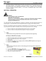
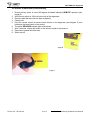
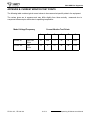
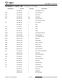
COMPLETE SOLUTIONS FOR MAGNETIC MEDIA MANAGEMENT
V660 HDD Evo
Hard Disk Drive Degausser
OPERATING & MAINTENANCE
MANUAL
V660 HDD Evo Degausser
Thank you for purchasing a Verity Systems
V660 HDD Evo Degausser
OPERATING & MAINTENANCE MANUAL
Document Reference No. M000301
Production Standard
ZZ 009 167 (60 Hz)
ZZ 009 168 (50Hz)
VERITY SYSTEMS LTD
VERITY SYSTEMS, INC.
2 Eastern Road
5441 Merchant Circle, Unit A
Aldershot
Placerville
Hampshire
California
GU12 4TD
95667
United Kingdom
United States
Tel: +44 (0) 1252 317000
Tel: (530) 626-9363
Fax: +44 (0) 1252 316555
Fax: (530) 626-9395
Email: [email protected]
Email: [email protected]
www.veritysystems.com
ZZ 009 167; ZZ 009 168
2 of 21
Operating & Maintenance Manual
V660 HDD Evo Degausser
WARNING!
This unit emits a strong magnetic field. Remove wrist watches before use. Personnel
fitted with a Cardiac Pacemaker should not stand within 0.5 metres of the unit.
Operating periods in excess of specified duration will result in exterior surfaces
becoming very hot.
To help minimise the possibility of electrical shock hazards
under no circumstances should any panels be removed
CAUTION!
It is recommended that magnetic storage media is kept at least 2 metres from the
degausser
IMPORTANT!
The power on/off switch used on this equipment is not an isolating switch. it is
recommended that this equipment should be operated from a separate switched
isolator which should be located close to the unit and within reach of the operator.
©
COPYRIGHT
This document is the property of Verity Systems and it may not be
reproduced, copied or exhibited to a third party without the written
permission of Verity Systems.
Verity Systems reserves the right to amend or modify the specifications
and design criteria applying to these products.
ZZ 009 167; ZZ 009 168
3 of 21
Operating & Maintenance Manual
V660 HDD Evo Degausser
Table of Contents
Section 1 SPECIFICATION
6
Section 2 INTRODUCTION
7
Section 3 INSTALLATION
8-9
3.1 Unpacking
8
3.2 Power Requirements
8-9
Section 4 OPERATION
9-10
4.1 Erasure of Hard Disk Drives – Locally
9-10
4.2 Erasure of Hard Disk Drives – Remotely
Section 5 INDICATORS/FEATURES
11
5.1 Indicators
11
5.2 Warning Indicators
11
5.3 IR Sensor
11
5.4 Overheat Protection
11
5.5 Cooling
11
5.6 Protection
11
Section 6 MAINTENANCE/SERVICE
11-13
6.1 Circuit Breaker
11
6.2 Bulb Replacement
12
6.3 Coolong Fan
12
6.4 Internal Components
12-13
Section 7 TECHNICAL SUPPORT
ZZ 009 167; ZZ 009 168
4 of 21
13
Operating & Maintenance Manual
V660 HDD Evo Degausser
Table of Contents Cont’d
Appendix A Basic Fault Finding Table
14-15
Appendix B Current Monitor Test Points
16
Appendix C Parts List
17-18
Appendix D Circuit Diagrams
19-20
ZZ 009 167; ZZ 009 168
5 of 21
Operating & Maintenance Manual
V660 HDD Evo Degausser
SECTION 1: SPECIFICATION
Hard Drives Erased
3½" PC Hard Disk Drives
Power Requirements
(factory set)
ZZ 009 167
ZZ 009 168
220/240v
115v
Line Frequency:
50Hz
60Hz
Current (typical):
10A
14A
Protection Circuit
12A
16A
Line Voltage:
Erasure Time:
5 seconds typical
Run Time:
10 minutes typical
Duty cycle :
Non-continuous. Average 10 minutes.
Mounting:
Free standing table top
Overall Dimensions:
Depth:19 inches (480mm)
Width: 16.5 inches (420mm)
Height: 6 inches (150mm)
Weight:
ZZ 009 167; ZZ 009 168
Approximately 77lbs/35kg
6 of 21
Operating & Maintenance Manual
V660 HDD Evo Degausser
SECTION 2: INTRODUCTION
The V660 HDD Evo degausser functions like a large electro magnet, its erasing field originating as
leakage flux from a large gap in the field structure, the V660’s structure is basically a U section. The
field intensity decreases rapidly as the distance from the degausser surface increases. For example at
a distance of approximately 2.75 inches from the degausser's surface a field strength of only 50
oersteds exists. Furthermore, the erasing field present at the front edge nearest the operator is also
very low.
Hard Disk Drives
The vulnerability of information stored on PC hard drives is a recognised security risk. Unlike other PC
data storage media the hard drive always stays with the PC. Every time a PC leaves a company’s
control all the data and company information will go with it.
Even if the hard drive breaks down the storage platters will still contain information which could be
read once repaired.
In keeping with our policy of recognising user requirements we have introduced the V660 HDD Evo
eraser. The V660 HDD Evo is capable of removing data from PC hard drives in less than 5 seconds.
Although in most cases this will render the hard drive inoperative, the cost of a replacement hard drive
cannot be compared to the cost to a company if sensitive information can be read by a third party.
ZZ 009 167; ZZ 009 168
7 of 21
Operating & Maintenance Manual
V660 HDD Evo Degausser
SECTION 3: INSTALLATION
3.1 Unpacking
Unpack the degausser carefully, and verify that all parts are present. If there are missing or
damaged parts contact Verity Systems or an authorised partner/reseller immediately to correct
any miss-packed or missing parts.
You should find the following :
Verity Systems V660 HDD Evo degausser
Infrared remote control switch
Power cable
This user manual
3.2 Power Requirements
Check the power supply requirements on the label attached to the back of the equipment with
the available supply. The unit is supplied with a flying 3 wire cable which, when connected to a
properly wired receptacle, earths the unit. It is essential that a proper earth connection is made
to assure safe operation.
Caution!
A good electrical ground must be connected to the degausser. The unit must be connected
to the correct power supply. Failure to do so may result in permanent damage.
Connections
Wire Colour
Brown
Blue
Yellow/Green
50 Hz
60 Hz
Live
Hot
Neutral
Cold
Earth
Ground
IMPORTANT INSTRUCTION
The mains supply outlet socket should be close to the installed equipment and fully accessible.
Note:
Degausser Current Consumption
The degaussing coils are powered as part of a tuned resonant circuit. This allows quite
high circulating currents to be generated within the degaussing coils, with minimal current
consumption from the mains voltage supply. However, this technique requires that the
waveform of the supply voltage contains minimal harmonic distortion. A distorted waveform will
result in an increase in current consumption. In extreme cases excessive current will trip the
circuit breaker making it necessary to use a mains filter to remove the distortion and reduce the
current consumption.
ZZ 009 167; ZZ 009 168
8 of 21
Operating & Maintenance Manual
V660 HDD Evo Degausser
The typical current consumption figures provided in this manual are when powered from a supply
with minimal distortion. Any increase in current consumption due to a distorted waveform will
have minimal effect on the degausser performance, however, excessive current consumption
should be avoided for obvious reasons. In the event of unexplained high currents, please
consult your supplier.
SECTION 4: OPERATION
WARNING!
STRONG MAGNETIC FIELDS ARE GENERATED.
REMOVE WATCHES BEFORE USE
ENSURE THAT THE FAN OPERATES CORRECTLY DURING USE. (AFTER INITIAL WARM UP PERIOD).
OPERATING PERIODS IN EXCESS OF SPECIFIED DURATION WILL RESULT IN EXTERIOR
SURFACES BECOMING VERY HOT.
The V660 HDD Evo has been designed for simplicity of operation and erases hard disk drives in a
single operation. The V660 HDD Evo can be operated locally or remotely via the infrared control
Because of the different types and manufactures specifications of PC hard disk units, Verity Systems
only recommends the erasure of hard disk units as a security precaution for the following.
a.
b.
Erasure of data from a faulty disk pack before being sent for service/repair.
Erasure of data from disk packs before disposal of computer equipment.
Note:
Verity Systems cannot guarantee that a drive will be operational after degaussing.
4.1 Erasure of Hard Drives Locally
1.
2.
3.
4.
5.
With the red power switch off, lift the lid on the top of the degausser.
Place the hard disk drive into the foam receptacle.
Close the lid
Ensure the key switch is in the upright position indicating LOCAL operation (see image A).
Press the red POWER switch
Note:
The illuminating on/off power switch is of the latching push button type which energises the
degaussing coil.
6.
7.
8.
The yellow DEGAUSS indicator light will illuminate.
After 5 seconds, press the red POWER switch to stop erasure
Remove the erased hard disk drive
Image A
ZZ 009 167; ZZ 009 168
9 of 21
Operating & Maintenance Manual
V660 HDD Evo Degausser
4.2 Erasure of Hard Disk Drives Remotely
1.
2.
3.
4.
5.
6.
7.
8.
9.
Ensure the key switch is turned 90 degrees clockwise indicating REMOTE operation (see
image B).
With the unit switch on, lift the lid on the top of the degausser.
Place the hard disk drive into the foam receptacle.
Close the lid.
Point the remote control at remote control sensor on the degausser (see diagram C) and
hold down the large button on the control.
The yellow DEGAUSS indicator light will illuminate.
After 5 seconds, release the button on the remote control to stop erasure.
Remove the erased hard disk drive.
Switch unit off
Image B
Image C
ZZ 009 167; ZZ 009 168
10 of 21
Operating & Maintenance Manual
V660 HDD Evo Degausser
SECTION 5: INDICATORS/FEATURES
5.1 Indicator
The degauss indicator (large yellow button) is provided to give an indication of degausser coil
energisation. Certain circumstances can arise when, although the unit is switched on, the
degauss coils may not be energised.
5.2 Warning indicator
The field failure indicator is provided to give further reassurance that the degauss field is
present. The indicator is considered more reliable being a red LED.
5.3 IR Transmitter
The infrared transmitter LED illuminates when the remote control is in operation.
5.4 Overheat Protection
The high energy field developed by the V660 HDD Evo necessitates the generation of a
considerable amount of heat.
The degausser coil is monitored for excessively high temperatures and should this condition
occur its operation will be inhibited until the coil has cooled sufficiently.
5.5 Cooling
A thermostatically controlled cooling fan is provided to extend the operating period to a
maximum.
5.6 Protection
The unit is protected by a thermal type circuit breaker. The current rating depends on the
specified operating voltage.
Degauss
Indicator Lights
Infrared Sensor
Remote/Local
Operation
Key Switch
IR Transmitter
Local Degauss
On/Off Button
ZZ 009 167; ZZ 009 168
11 of 21
Operating & Maintenance Manual
V660 HDD Evo Degausser
SECTION 6: MAINTENANCE/SERVICING
The unit is basically maintenance free but periodic checks should be made to ensure the correct
operation of the fan and the good condition of the power cable.
Note:
To reduce the risk of shock hazard, disconnect the degausser from the mains voltage supply
before carrying out any maintenance or servicing.
6.1 Circuit Breaker
To reset the circuit breaker simply 'push in' and 'release' the button.
6.2 Bulb Replacement
Note:
Remove Power from the unit before replacing bulbs.
6.2.1
Remove the "bulb lens" from the "switch/indicator body" by levering it forwards.
Neon Voltage
Model
Power Switch
Indicator
ZZ 009 167
220-240v
220-240v
ZZ 009 168
115v
220-240v
6.2.2
Remove the bulb from the rear of the "bulb housing" using a suitable extraction tool.
6.2.3
Replace the bulb noting the following:
Note:
The bulb will fit in only one position in a locating slot. If when fitting this does not occur,
remove the bulb and rotate it through 180°.
6.2.4
Refit the "bulb lens" to the "switch/indicator body" gently pushing the lens into the "switch/
indicator body" housing.
ZZ 009 167; ZZ 009 168
12 of 21
Operating & Maintenance Manual
V660 HDD Evo Degausser
6.3 Cooling Fan
The cooling fan is of the conventional axial type powered from the ac voltage supply. The unit
is over temperature and over current protected and does not require servicing. However in the
event of failure the fan may easily be replaced from the rear of the degausser.
6.4 Internal Components
Most of the internal components are replaceable, i.e. the solid state relay, toroidal transformer
(60Hz only) and the thermal switches mounted on the degausser coil. However the tuning
capacitors and the degaussing coil are not spared items and if found to be faulty the unit
should be returned to Verity Systems for repair.
To access the components inside the degausser the laminate cover must be removed. This
entails breaking the adhesive seal using a sharp blade.
6.4.1 Solid State Relay Replacement
A thermally conductive compound should be used to ensure adequate heat dissipation
from the relay to the metal case.
6.4.2 Thermal Switch Replacement
Care must be exercised when replacing either of the switches on the degausser coil. The
switches are fitted using an epoxy resin and it is recommended that the new switch be
fitted in a new position on the coil and the old switch be left in place. The wire connections
are of the 'push on' spade type and are easily transferred to the new switch. A high
temperature epoxy resin part no. EA 200 001 should be used to secure the new switch.
6.4.3 Cover replacement
The laminate cover should be cleaned of old adhesive before refitting, using the sealant
part no. EA 100 007 and high temperature tape, Part No. HS100143
SECTION 7: TECHNICAL SUPPORT
You should first attempt to get technical assistance from your dealer or authorised partner/reseller.
Verity Systems support personnel can be reached at:
Verity Systems Ltd.
2 Eastern Road
Aldershot
Hampshire
GU12 4TD
United Kingdom
Tel: +44 (0) 1252 317000
Fax: +44 (0) 1252 316555
E-mail: [email protected]
ZZ 009 167; ZZ 009 168
Verity Systems, Inc.
5441 Merchant Circle, Unit A
Placerville
CA 956567
United States
Toll Free: (800) 642-5151
Tel: (530) 626-9363
Fax: (530) 626-9395
E-mail: [email protected]
13 of 21
Operating & Maintenance Manual
V660 HDD Evo Degausser
APPENDIX A – BASIC FAULT TABLE
The table assists fault finding down to component levels. However, should the degaussing coil or
tuning capacitors be found to be faulty it is recommended that the unit be returned to Verity Systems
for repair.
Function
Fails to erase drive
Symptoms
Possible Fault
Circuit Breaker
CB1 repeatedly
tripped
Incorrect supply
voltage.frequency
User source
Faulty degauss coil
L1 and /or tuning
capacitors C1-C4
Inside centre, left
hand side
Loss of mains
supply.
User source
Tripped circuit
breaker
Rear panel
Faulty switch
Front panel
Faulty Neon
Front panel
and
Power Lamp
Degauss lamp &
Warning Lamp
Fails to illuminate
Fails to illuminate
Location
Extensive use of
degausser caused
overheating. Allow
unit to cool (not a
fault).
Faulty neon
Front panel
Faulty solid state
relay R1
Inside on right hand
side
Faulty thermal switch Inside on front end
SW2
of degaussing coil
Faulty transformer
TX1 (115v 60 Hz
only)
Cooling Fan
Fails to Operate
Faulty thermal switch Inside on front end
SW3
of degaussing coil
Faulty Fan M1
ZZ 009 167; ZZ 009 168
Inside front on left
hand side
14 of 21
Rear Panel
Operating & Maintenance Manual
V660 HDD Evo Degausser
Note:
Degausser Current Consumption
The degaussing coils are powered as part of a tuned resonant circuit. This allows
quite high circulating currents to be generated within the degaussing coils, with
minimal current consumption from the mains voltage supply. However, this
technique requires that the waveform of the supply voltage contains minimal
harmonic distortion. A distorted waveform will result in an increase in current
consumption.
The typical current consumption figures provided in this manual are when powered
from a supply with minimal distortion. Any increase in current consumption due to
a distorted waveform will have minimal effect on the degausser performance,
however, excessive current consumption should be avoided for obvious reasons.
In the event of unexplained high currents, please consult your supplier.
ZZ 009 167; ZZ 009 168
15 of 21
Operating & Maintenance Manual
V660 HDD Evo Degausser
APPENDIX B: CURRENT MONITOR TEST POINTS
The following table contains typical current values to be measured at specific points in the equipment.
The values given are in amperes and may differ slightly from those actually
component tolerance plus effects due to operating temperature.
Model Voltage/Frequency
measured due to
Current Monitor Test Points
1
2
3
4
5
6
ZZ 009 167
220v-240v
50 Hz
10
N/A
71
30
37
0.09
ZZ 009 168
115v
60 Hz
14
8
72
39
29
0.19
ZZ 009 167; ZZ 009 168
16 of 21
Operating & Maintenance Manual
V660 HDD Evo Degausser
APPENDIX C: PARTS LIST – ZZ 009 168 (115V 60Hz)
Designation
Part No.
Quantity
Description
CA 100 005
1
Cable gland 16mm
TB2
CG 200 001
4
Terminal Block
TB2
CG 200 002
1
End Cover
TB2
CG 200 003
0.4
Jump Bar
TB1
CM 100 023
0.25
Terminal Block
FM 100 033
1
Guard 120mm metal
FM 100 042
1
Fan 120mm
HS 100 101
4
Feet
Ind 1
OI 100 031
1
Neon
SW1
OI 100 030
1
Neon
RL1
RS 100 010
1
Relay
SW3
SW 100 061
1
Temperature Sensor
SW2
SW 100 060
2
Thermal Switch
CB1
SW 100 0143
1
Circuit Breaker 16A
SW1
SW 100 123
1
Red lens
SW1
SW 100 125
1
Switch Body
SW1
SW 100 126
1
Switch Contacts
IND1
SW 100 121
1
Yellow Lens
IND1
SW 100 124
1
Indicator Body
IND1
SW 100 127
1
Dummy Socket
TX1
TX 100 030
1
Auto Toroid Transformer
XX 003 065
1
Fan Plate
SW2
SW 100 070
1
‘Mode’ Key Switch
Ind2
OI 100 064
1
Led Indicator
R1
RP 200 035
1
390 ohm Resistor
RL2
XX 005 219
1
IR Sensor
D1
SD 100 025
1
Rectifier Diode
TX1
TX 100 069
1
Transformer
C6
CC 100 071
1
100 µf Capacitor
XX 005 274
1
Fixed top
XX 005 276
1
Hinged lid
XX 005 218
1
IR Transmitter
M1
ZZ 009 167; ZZ 009 168
17 of 21
Operating & Maintenance Manual
V660 HDD Evo Degausser
PARTS LIST – ZZ 009 167 (220-240V 50Hz)
Designation
Part No.
Quantity
Description
CA 100 005
1
Cable gland 16mm
TB2
CG 200 001
4
Terminal Block
TB2
CG 200 002
1
End Cover
TB2
CG 200 003
0.4
Jump Bar
TB1
CM 100 023
0.25
Terminal Block
FM 100 033
1
Guard 120mm metal
FM 100 027
1
Fan 120mm
HS 100 101
4
Feet
SW1 & Ind 1
OI 100 031
2
Neon
RL1
RS 100 010
1
Relay
SW3
SW 100 061
1
Temperature Sensor
SW2
SW 100 060
2
Thermal Switch
CB1
SW 100 066
1
Circuit Breaker 12A
SW1
SW 100 123
1
Red lens
SW1
SW 100 125
1
Switch Body
SW1
SW 100 126
1
Switch Contacts
IND1
SW 100 121
1
Yellow Lens
IND1
SW 100 124
1
Indicator Body
IND1
SW 100 127
1
Dummy Socket
XX 003 065
1
Fan Plate
SW4
SW 100 070
1
‘Mode’ Key Switch
Ind2
OI 100 064
1
Led Indicator
R1
RP 200 035
1
390 ohm Resistor
RL2
Xx 005 219
1
IR Sensor
D1
SD 100 025
1
Rectifier Diode
TX1
TX 100 069
1
Transformer
C6
CC 100 071
1
100 µf Capacitor
L1
MP 002 325
M1
ZZ 009 167; ZZ 009 168
Filter
XX 005 274
1
Fixed Top
XX 005 276
1
Hinged Lid
XX 005 218
1
IR Transmitter
18 of 21
Operating & Maintenance Manual
V660 HDD Evo Degausser
ZZ 009 167; ZZ 009 168
19 of 21
Operating & Maintenance Manual
V660 HDD Evo Degausser
ZZ 009 167; ZZ 009 168
20 of 21
Operating & Maintenance Manual
Supplied by:
Verity Systems Ltd.
2 Eastern Road
Verity Systems, Inc.
5441 Merchant Circle, Unit A
Aldershot
Placerville
Hampshire
CA 95567
GU12 4TD
United States
United Kingdom
Toll Free: (800) 642-5151
Tel: +44 (0) 1252 317000
Tel: (530) 626-9363
Fax: +44 (0) 1252 316555
Fax: (530) 626-9395
E-mail: [email protected]
E-mail: [email protected]