1
LM3421, LM3421-Q1
LM3423, LM3423-Q1
www.ti.com
SNVS574E – JULY 2008 – REVISED MAY 2013
N-Channel Controllers for Constant Current LED Drivers
Check for Samples: LM3421, LM3421-Q1, LM3423, LM3423-Q1
FEATURES
DESCRIPTION
•
The LM3421/23 are versatile high voltage N-channel
MosFET controllers for LED drivers . They can be
easily configured in buck, boost, buck-boost and
SEPIC topologies. This flexibility, along with an input
voltage rating of 75V, makes the LM3421/23 ideal for
illuminating LEDs in a large family of applications.
1
2
•
•
•
•
•
•
•
•
•
•
LM3421Q1/LM3423Q1 are Automotive Grade
Products That are AEC-Q100 Grade 1 Qualified
(-40°C to +125°C Operating Junction
Temperature) and Similarly
LM3421Q0/LM3423Q0 are AEC-Q100 Grade 0
Qualified (-40°C to +150°C Operating Junction
Temperature)
VIN Range From 4.5V to 75V
High-Side Adjustable Current Sense
2Ω, 1A Peak MosFET Gate Driver
Input Under-Voltage and Output Over-Voltage
Protection
PWM and Analog Dimming
Cycle-by-Cycle Current Limit
Programmable Switching Frequency
"Zero Current" Shutdown and Thermal
Shutdown
LED Output Status Flag (LM3423/23Q1/23Q0
Only)
Fault Status Flag and Timer
(LM3423/23Q1/23Q0 Only)
APPLICATIONS
•
•
•
•
•
LED Drivers - Buck, Boost, Buck-Boost, and
SEPIC
Indoor and Outdoor Area SSL
Automotive
General Illumination
Constant-Current Regulators
Adjustable high-side current sense voltage allows for
tight regulation of the LED current with the highest
efficiency possible. The LM3421/23 uses Predictive
Off-time (PRO) control, which is a combination of
peak current-mode control and a predictive off-timer.
This method of control eases the design of loop
compensation while providing inherent input voltage
feed-forward compensation.
The LM3421/23 devices include a high-voltage
startup regulator that operates over a wide input
range of 4.5V to 75V. The internal PWM controller is
designed for adjustable switching frequencies of up to
2.0 MHz, thus enabling compact solutions. Additional
features include "zero current" shutdown, analog
dimming, PWM dimming, over-voltage protection,
under-voltage lock-out, cycle-by-cycle current limit,
and thermal shutdown.
The LM3423 also includes an LED output status flag,
a fault flag, a programmable fault timer, and a logic
input to select the polarity of the dimming output
driver.
The LM3421Q1/23Q1 are AEC-Q100 grade 1
qualified and LM3421Q0/23Q0 are AEC-Q100 grade
0 qualified.
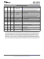
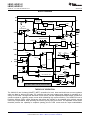
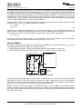
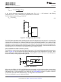
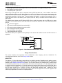
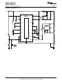
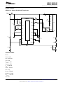
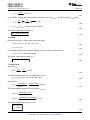
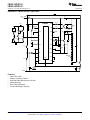
Typical Boost Application Circuit
VIN
1
2
3
4
5
6
7
VIN
LM3421
HSN
EN
HSP
COMP
RPD
CSH
IS
RCT
VCC
GATE
AGND
PGND
OVP
16
15
14
13
12
ILED
11
10
DAP
PWM
8
nDIM
DDRV
9
1
2
Please be aware that an important notice concerning availability, standard warranty, and use in critical applications of
Texas Instruments semiconductor products and disclaimers thereto appears at the end of this data sheet.
All trademarks are the property of their respective owners.
PRODUCTION DATA information is current as of publication date.
Products conform to specifications per the terms of the Texas
Instruments standard warranty. Production processing does not
necessarily include testing of all parameters.
Copyright © 2008–2013, Texas Instruments Incorporated
LM3421, LM3421-Q1
LM3423, LM3423-Q1
SNVS574E – JULY 2008 – REVISED MAY 2013
www.ti.com
EFFICIENCY (%)
100
95
90
85
80
10
15
20
25
30
VIN (V)
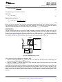
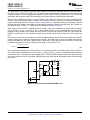
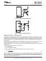
Figure 1. Boost Evaluation Board
9 Series LEDs at 1A
Connection Diagrams
Top View
Top View
VIN
1
16 HSN
1
20 HSN
EN
2
15 HSP
EN 2
19 HSP
COMP 3
14 RPD
COMP 3
18 RPD
CSH
4
DAP
RCT 5
17
VIN
13 IS
CSH 4
12 VCC
RCT 5
17 IS
DAP
21
16 VCC
15 GATE
11 GATE
AGND 6
OVP 7
10 PGND
OVP 7
14 PGND
nDIM 8
9
DDRV
nDIM 8
13 DDRV
FLT 9
12 DPOL
TIMR 10
11 LRDY
AGND 6
Figure 2. 16-Lead TSSOP
Package Number PWP
Figure 3. 20-Lead TSSOP
Package Number PWP
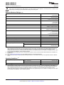
PIN DESCRIPTIONS
LM3423
2
LM3421
Name
Description
1
1
VIN
Input Voltage
2
2
EN
Enable
3
3
COMP
Compensation
4
4
CSH
Current Sense High
5
5
RCT
Resistor Capacitor Timing
6
6
AGND
Analog Ground
7
7
OVP
Over-Voltage Protection
Submit Documentation Feedback
Function
Bypass with 100 nF capacitor to AGND as close to the device as
possible in the circuit board layout.
Connect to AGND for zero current shutdown or apply > 2.4V to
enable device.
Connect a capacitor to AGND to set the compensation.
Connect a resistor to AGND to set the signal current. For analog
dimming, connect a controlled current source or a potentiometer to
AGND as detailed in the ANALOG DIMMING section.
External RC network sets the predictive “off-time” and thus the
switching frequency.
Connect to PGND through the DAP copper pad to provide ground
return for CSH, COMP, RCT, and TIMR.
Connect to a resistor divider from VO to program output over-voltage
lockout (OVLO). Turn-off threshold is 1.24V and hysteresis for turn-on
is provided by 23 µA current source.
Copyright © 2008–2013, Texas Instruments Incorporated
Product Folder Links: LM3421 LM3421-Q1 LM3423 LM3423-Q1
LM3421, LM3421-Q1
LM3423, LM3423-Q1
www.ti.com
SNVS574E – JULY 2008 – REVISED MAY 2013
PIN DESCRIPTIONS (continued)
LM3423
LM3421
Name
Description
Function
Connect a PWM signal for dimming as detailed in the PWM
DIMMING section and/or a resistor divider from VIN to program input
under-voltage lockout (UVLO). Turn-on threshold is 1.24V and
hysteresis for turn-off is provided by 23 µA current source.
8
8
nDIM
Dimming Input /
Under-Voltage Protection
9
-
FLT
Fault Flag
10
-
TIMR
Fault Timer
11
-
LRDY
LED Ready Flag
Connect to pull-up resistor from VIN and N-channel MosFET open
drain output pulls down when the LED current is not in regulation.
12
-
DPOL
Dim Polarity
Connect to AGND if dimming with a series P-channel MosFET or
leave open when dimming with series N-channel MosFET.
13
9
DDRV
Dim Gate Drive Output
14
10
PGND
Power Ground
15
11
GATE
Main Gate Drive Output
16
12
VCC
Internal Regulator Output
17
13
IS
Main Switch Current Sense
18
14
RPD
Resistor Pull Down
19
15
HSP
LED Current Sense Positive
Connect through a series resistor to the positive side of the LED
current sense resistor.
20
16
HSN
LED Current Sense Negative
Connect through a series resistor to the negative side of the LED
current sense resistor.
DAP (21)
DAP (17)
DAP
Thermal PAD on bottom of IC
Star ground, connecting AGND and PGND. For thermal
considerations please refer to (1).
(1)
Connect to pull-up resistor from VIN and N-channel MosFET open
drain output is high when a fault condition is latched by the timer.
Connect a capacitor to AGND to set the time delay before a sensed
fault condition is latched.
Connect to the gate of the dimming MosFET.
Connect to AGND through the DAP copper pad to provide ground
return for GATE and DDRV.
Connect to the gate of the main switching MosFET.
Bypass with 2.2 µF–3.3 µF ceramic capacitor to PGND.
Connect to the drain of the main N-channel MosFET switch for RDSON sensing or to a sense resistor installed in the source of the same
device.
Connect the low side of all external resistor dividers (VIN UVLO, OVP)
to implement “zero-current” shutdown.
Junction-to-ambient thermal resistance is highly board-layout dependent. The numbers listed in the table are given for an reference
layout wherein the 16L TSSOP package has its EP pad populated with 9 vias and the 20L TSSOP has its EP pad populated with 12
vias. In applications where high maximum power dissipation exists, namely driving a large MosFET at high switching frequency from a
high input voltage, special care must be paid to thermal dissipation issues during board design. In high-power dissipation applications,
the maximum ambient temperature may have to be derated. Maximum ambient temperature (TA-MAX) is dependent on the maximum
operating junction temperature (TJ-MAX-OP = 125°C for Q1, or 150°C for Q0), the maximum power dissipation of the device in the
application (PD-MAX), and the junction-to ambient thermal resistance of the package in the application (θJA), as given by the following
equation: TA-MAX = TJ-MAX-OP – (θJA × PD-MAX). In most applications there is little need for the full power dissipation capability of this
advanced package. Under these circumstances, no vias would be required and the thermal resistances would be 104 °C/W for the 16L
TSSOP and 86.7 °C/W for the 20L TSSOP. It is possible to conservatively interpolate between the full via count thermal resistance and
the no via count thermal resistance with a straight line to get a thermal resistance for any number of vias in between these two limits.
Copyright © 2008–2013, Texas Instruments Incorporated
Submit Documentation Feedback
Product Folder Links: LM3421 LM3421-Q1 LM3423 LM3423-Q1
3
LM3421, LM3421-Q1
LM3423, LM3423-Q1
SNVS574E – JULY 2008 – REVISED MAY 2013
www.ti.com
These devices have limited built-in ESD protection. The leads should be shorted together or the device placed in conductive foam
during storage or handling to prevent electrostatic damage to the MOS gates.
Absolute Maximum Ratings
(1) (2)
VIN, EN, RPD, nDIM
-0.3V to 76.0V
-1 mA continuous
OVP, HSP, HSN, LRDY, FLT, DPOL
-0.3V to 76.0V
-100 µA continuous
RCT
-0.3V to 76.0V
-1 mA to +5 mA continuous
IS
-0.3V to 76.0V
-2V for 100 ns
-1mA continuous
VCC
-0.3V to 8.0V
TIMR
-0.3V to 7.0V
-100µA to +100µA Continuous
COMP, CSH
-0.3V to 6.0V
-200 µA to +200 µA Continuous
GATE, DDRV
-0.3V to VCC
-2.5V for 100 ns
VCC+2.5V for 100 ns
-1 mA to +1 mA continuous
PGND
-0.3V to 0.3V
-2.5V to 2.5V for 100 ns
Maximum Junction Temperature
Internally Limited
−65°C to +150°C
Storage Temperature Range
Maximum Lead Temperature (Solder and Reflow)
(3)
260°C
Continuous Power Dissipation
Internally Limited
ESD Susceptibility (4)
Human Body Model
2 kV
Charge Device Model
(1)
(2)
(3)
(4)
500V CSH pin
750V all other pins
Absolute Maximum Ratings indicate limits beyond which damage to the device may occur, including inoperability and degradation of
device reliability and/or performance. Functional operation of the device and/or non-degradation at the Absolute Maximum Ratings or
other conditions beyond those indicated in the Operating Ratings is not implied. The recommended Operating Ratings indicate
conditions at which the device is functional and the device should not be operated beyond such conditions. All voltages are with respect
to the potential at the AGND pin, unless otherwise specified.
If Military/Aerospace specified devices are required, please contact the Texas Instruments Sales Office/Distributors for availability and
specifications.
Refer to http://www.ti.com/packaging for more detailed information and mounting techniques.
The human body model is a 100 pF capacitor discharged through a 1.5 kΩ resistor into each pin. The applicable standard is JESD22A114C.
Operating Conditions
(1)
Operating Junction Temperature Range
LM3421, LM3421Q1,
LM3423, LM3423Q1
−40°C to +125°C
LM3421Q0, LM3423Q0
−40°C to +150°C
Input Voltage VIN
(1)
4
4.5V to 75V
Absolute Maximum Ratings indicate limits beyond which damage to the device may occur, including inoperability and degradation of
device reliability and/or performance. Functional operation of the device and/or non-degradation at the Absolute Maximum Ratings or
other conditions beyond those indicated in the Operating Ratings is not implied. The recommended Operating Ratings indicate
conditions at which the device is functional and the device should not be operated beyond such conditions. All voltages are with respect
to the potential at the AGND pin, unless otherwise specified.
Submit Documentation Feedback
Copyright © 2008–2013, Texas Instruments Incorporated
Product Folder Links: LM3421 LM3421-Q1 LM3423 LM3423-Q1
LM3421, LM3421-Q1
LM3423, LM3423-Q1
www.ti.com
SNVS574E – JULY 2008 – REVISED MAY 2013
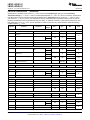
Electrical Characteristics
(1)
Specifications in standard type face are for TJ = 25°C and those with boldface type apply over the full Operating
Temperature Range ( TJ = −40°C to +150°C for LM3421Q0/LM3423Q0, TJ = −40°C to +125°C for all others). Specifications
that differ between the two operating ranges will be identified in the Temp Range column as Q0 for TJ = −40°C to +150°C
and as Q1 for TJ = −40°C to +125°C. If no temperature range is indicated then the specification holds for both Q1 and Q0.
Minimum and Maximum limits are specified through test, design, or statistical correlation. Typical values represent the most
likely parametric norm at TJ = +25°C, and are provided for reference purposes only. Unless otherwise stated the following
condition applies: VIN = +14V.
Symbol
Parameter
Conditions
Temp
Range
Min (2)
Typ (3)
Max (2)
Units
6.30
6.90
7.35
V
20
25
3
mA
STARTUP REGULATOR
VCCREG
VCC Regulation
ICC = 0 mA
ICCLIM
VCC Current Limit
VCC = 0V
IQ
Quiescent Current
EN = 3.0V, Static
Q1
2
Q0
ISD
3.5
Shutdown Current
EN = 0V
0.1
1.0
VCCUV
VCC UVLO Threshold
VCC Increasing
4.17
4.50
VCCHYS
VCC UVLO Hysteresis
µA
VCC SUPPLY
VCC Decreasing
3.70
4.08
V
0.1
EN THRESHOLDS
ENST
EN Startup Threshold
EN Increasing
Q1
1.75
Q0
EN Decreasing
ENSTHYS
EN Startup Hysteresis
REN
EN Pulldown Resistance
0.80
2.40
2.75
1.63
V
0.1
EN = 1V
Q1
Q0
0.45
0.82
1.30
1.80
MΩ
CSH THRESHOLDS
CSH High Fault
CSH Increasing
CSH Low Condition on LRDY
Pin (LM3423)
CSH increasing
1.6
V
1.0
OV THRESHOLDS
OVPCB
OVP OVLO Threshold
OVP Increasing
OVPHYS
OVP Hysteresis Source
Current
OVP Active (high)
1.185
Q1
Q0
1.240
1.285
25
V
20
23
2.0
2.3
2.6
V
500
1200
kΩ
26
µA
DPOL THRESHOLDS
DPOLTHRES
DPOL Logic Threshold
DPOL Increasing
H
RDPOL
DPOL Pullup Resistance
FAULT TIMER
VFLTTH
Fault Threshold
Q1
Q0
IFLT
Fault Pin Source Current
Q1
Q0
(1)
(2)
(3)
1.185
1.240
10.0
11.5
1.285
1.290
13.0
13.5
V
µA
Absolute Maximum Ratings indicate limits beyond which damage to the device may occur, including inoperability and degradation of
device reliability and/or performance. Functional operation of the device and/or non-degradation at the Absolute Maximum Ratings or
other conditions beyond those indicated in the Operating Ratings is not implied. The recommended Operating Ratings indicate
conditions at which the device is functional and the device should not be operated beyond such conditions. All voltages are with respect
to the potential at the AGND pin, unless otherwise specified.
All limits specified at room temperature (standard typeface) and at temperature extremes (bold typeface). All room temperature limits are
100% production tested. All limits at temperature extremes are specified via correlation using standard Statistical Quality Control (SQC)
methods. All limits are used to calculate Average Outgoing Quality Level (AOQL).
Typical numbers are at 25°C and represent the most likely norm.
Copyright © 2008–2013, Texas Instruments Incorporated
Submit Documentation Feedback
Product Folder Links: LM3421 LM3421-Q1 LM3423 LM3423-Q1
5
LM3421, LM3421-Q1
LM3423, LM3423-Q1
SNVS574E – JULY 2008 – REVISED MAY 2013
www.ti.com
Electrical Characteristics (1) (continued)
Specifications in standard type face are for TJ = 25°C and those with boldface type apply over the full Operating
Temperature Range ( TJ = −40°C to +150°C for LM3421Q0/LM3423Q0, TJ = −40°C to +125°C for all others). Specifications
that differ between the two operating ranges will be identified in the Temp Range column as Q0 for TJ = −40°C to +150°C
and as Q1 for TJ = −40°C to +125°C. If no temperature range is indicated then the specification holds for both Q1 and Q0.
Minimum and Maximum limits are specified through test, design, or statistical correlation. Typical values represent the most
likely parametric norm at TJ = +25°C, and are provided for reference purposes only. Unless otherwise stated the following
condition applies: VIN = +14V.
Symbol
Parameter
Conditions
Temp
Range
Min (2)
Typ (3)
Max (2)
Units
1.210
1.235
1.260
V
-0.6
0
0.6
22
30
ERROR AMPLIFIER
VREF
CSH Reference Voltage
With Respect to AGND
Error Amplifier Input Bias
Current
COMP Sink / Source Current
Q1
Q0
Transconductance
(4)
Linear Input Range
Transconductance Bandwidth
-6dB Unloaded Response
(4)
Minimum Off-time
RCT = 1V through
1 kΩ
Q1
0.5
35
µA
36
100
µA/V
±125
mV
1.0
MHz
OFF TIMER
RRCT
RCT Reset Pull-down
Resistance
VRCT
Q0
Q1
36
Q0
VIN/25 Reference Voltage
VIN = 14V
Q1
Q0
f
35
Continuous Conduction
Switching Frequency
540
2.2 nF > CT > 470 pF
565
75
90
120
125
585
590
25/(CTRT)
ns
Ω
mV
Hz
PWM COMPARATOR
COMP to PWM Offset
700
800
900
mV
215
245
275
mV
CURRENT LIMIT (IS)
ILIM
Current Limit Threshold
ILIM Delay to Output
Q1
35
Q0
Leading Edge Blanking Time
115
210
75
90
ns
325
HIGH SIDE TRANSCONDUCTANCE AMPLIFIER
Input Bias Current
11.5
µA
Transconductance
20
119
mA/V
Input Offset Current
-1.5
0
1.5
µA
Input Offset Voltage
-7
0
7
mV
250
500
Transconductance Bandwidth
ICSH = 100 µA
(4)
kHz
GATE DRIVER (GATE)
RSRC(GATE)
GATE Sourcing Resistance
GATE = High
2.0
6.0
RSNK(GATE)
GATE Sinking Resistance
GATE = Low
1.3
4.5
1.240
1.285
Ω
DIM DRIVER (DIM, DDRV)
nDIMVTH
nDIM / UVLO Threshold
nDIMHYS
nDIM Hysteresis Current
1.185
Q1
Q0
20
23
25
26
RSRC(DDRV)
DDRV Sourcing Resistance
DDRV = High
13.5
30.0
RSNK(DDRV)
DDRV Sinking Resistance
DDRV = Low
3.5
10.0
(4)
6
V
µA
Ω
These electrical parameters are specified by design, and are not verified by test.
Submit Documentation Feedback
Copyright © 2008–2013, Texas Instruments Incorporated
Product Folder Links: LM3421 LM3421-Q1 LM3423 LM3423-Q1
LM3421, LM3421-Q1
LM3423, LM3423-Q1
www.ti.com
SNVS574E – JULY 2008 – REVISED MAY 2013
Electrical Characteristics (1) (continued)
Specifications in standard type face are for TJ = 25°C and those with boldface type apply over the full Operating
Temperature Range ( TJ = −40°C to +150°C for LM3421Q0/LM3423Q0, TJ = −40°C to +125°C for all others). Specifications
that differ between the two operating ranges will be identified in the Temp Range column as Q0 for TJ = −40°C to +150°C
and as Q1 for TJ = −40°C to +125°C. If no temperature range is indicated then the specification holds for both Q1 and Q0.
Minimum and Maximum limits are specified through test, design, or statistical correlation. Typical values represent the most
likely parametric norm at TJ = +25°C, and are provided for reference purposes only. Unless otherwise stated the following
condition applies: VIN = +14V.
Symbol
Parameter
Conditions
Temp
Range
Min (2)
Typ (3)
Max (2)
Units
PULL-DOWN N-CHANNEL MosFETS
RRPD
RPD Pull-down Resistance
Q1
Q0
RFLT
FLT Pull-down Resistance
Q1
Q0
RLRDY
LRDY Pull-down Resistance
Q1
Q0
145
145
135
300
350
300
Ω
350
300
350
THERMAL SHUTDOWN
TSD
Thermal Shutdown Threshold
THYS
Thermal Shutdown Hysteresis
(4)
(4)
Q1
165
Q0
210
°C
25
THERMAL RESISTANCE
θJA
θJC
(5)
Junction to Ambient
(5)
Junction to Exposed Pad (EP)
16L TSSOP
37.4
20L TSSOP
34.0
16L TSSOP
2.3
20L TSSOP
2.3
°C/W
°C/W
Junction-to-ambient thermal resistance is highly board-layout dependent. The numbers listed in the table are given for an reference
layout wherein the 16L TSSOP package has its EP pad populated with 9 vias and the 20L TSSOP has its EP pad populated with 12
vias. In applications where high maximum power dissipation exists, namely driving a large MosFET at high switching frequency from a
high input voltage, special care must be paid to thermal dissipation issues during board design. In high-power dissipation applications,
the maximum ambient temperature may have to be derated. Maximum ambient temperature (TA-MAX) is dependent on the maximum
operating junction temperature (TJ-MAX-OP = 125°C for Q1, or 150°C for Q0), the maximum power dissipation of the device in the
application (PD-MAX), and the junction-to ambient thermal resistance of the package in the application (θJA), as given by the following
equation: TA-MAX = TJ-MAX-OP – (θJA × PD-MAX). In most applications there is little need for the full power dissipation capability of this
advanced package. Under these circumstances, no vias would be required and the thermal resistances would be 104 °C/W for the 16L
TSSOP and 86.7 °C/W for the 20L TSSOP. It is possible to conservatively interpolate between the full via count thermal resistance and
the no via count thermal resistance with a straight line to get a thermal resistance for any number of vias in between these two limits.
Copyright © 2008–2013, Texas Instruments Incorporated
Submit Documentation Feedback
Product Folder Links: LM3421 LM3421-Q1 LM3423 LM3423-Q1
7
LM3421, LM3421-Q1
LM3423, LM3423-Q1
SNVS574E – JULY 2008 – REVISED MAY 2013
www.ti.com
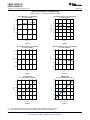
Typical Performance Characteristics
TA=+25°C and VIN = 14V unless otherwise specified
Boost Efficiency vs. Input Voltage
VO = 32V (9 LEDs) (1)
Buck-Boost Efficiency vs. Input Voltage
VO = 21V (6 LEDs) (2)
100
95
95
EFFICIENCY (%)
EFFICIENCY (%)
100
90
85
90
85
80
75
70
80
15
20
25
30
0
16
32
48
64
80
VIN (V)
VIN (V)
Figure 4.
Figure 5.
Boost LED Current vs. Input Voltage
VO = 32V (9 LEDs) (1)
Buck-Boost LED Current vs. Input Voltage
VO = 21V (6 LEDs) (2)
1.010
1.02
1.005
1.01
ILED (A)
ILED (A)
10
1.000
1.00
0.995
0.99
0.990
0.98
5
10
15
20
VIN (V)
25
30
0
16
32
48
64
80
VIN (V)
Figure 6.
Figure 7.
Analog Dimming
VO = 21V (6 LEDs); VIN = 24V
PWM Dimming
VO = 32V (9 LEDs); VIN = 24V
(2)
(1)
1.0
1.0
0.8
0.6
ILED (A)
ILED (A)
0.8
0.4
0.6
1 kHz
0.4
25 kHz
0.2
0.2
0.0
0.8
0
20
40
60
80
100
0
20
40
Figure 8.
(1)
(2)
8
60
80
100
DUTY CYCLE (%)
ICSH (éA)
Figure 9.
The measurements were made using the standard boost evaluation board from SNVA416.
The measurements were made using the standard buck-boost evaluation board from .
Submit Documentation Feedback
Copyright © 2008–2013, Texas Instruments Incorporated
Product Folder Links: LM3421 LM3421-Q1 LM3423 LM3423-Q1
LM3421, LM3421-Q1
LM3423, LM3423-Q1
www.ti.com
SNVS574E – JULY 2008 – REVISED MAY 2013
Typical Performance Characteristics (continued)
TA=+25°C and VIN = 14V unless otherwise specified
VCSH vs. Junction Temperature
VCC vs. Junction Temperature
7.20
1.250
7.10
1.240
7.00
VCC (V)
VCSH (V)
1.245
1.235
1.230
6.90
1.225
6.80
1.220
6.70
-50
-14
22
58
94
130
-50
-14
22
58
94
130
TEMPERATURE (°C)
TEMPERATURE (°C)
Figure 10.
Figure 11.
VRCT vs. Junction Temperature
VLIM vs. Junction Temperature
567
248
566
565
VLIM (mV)
VRCT (mV)
246
564
244
242
563
240
562
-50
-14
22
58
94
130
-50
-14
22
58
94
130
TEMPERATURE (°C)
TEMPERATURE (°C)
Figure 12.
Figure 13.
tON-MIN vs. Junction Temperature
225
tON-MIN (ns)
220
215
210
205
200
195
-50
-14
22
58
94
130
TEMPERATURE (°C)
Figure 14.
Copyright © 2008–2013, Texas Instruments Incorporated
Submit Documentation Feedback
Product Folder Links: LM3421 LM3421-Q1 LM3423 LM3423-Q1
9
LM3421, LM3421-Q1
LM3423, LM3423-Q1
SNVS574E – JULY 2008 – REVISED MAY 2013
www.ti.com
BLOCK DIAGRAM
VIN
6.9V LDO
Regulator
EN
VCC
820k
UVLO
(4.1V)
VCC UVLO
REFERENCE
500k
VIN UVLO
Standby
HYSTERESIS
23 PA
nDIM
1.235V
VCC
TLIM Thermal
DPOL
Limit
Dimming
1.24V
DDRV
OVLO
LatchOff
RCT
PGND
Reset
Dominant
Start new on time
VIN/25
LEB
VCC
Q
S
GATE
R
W = 150 ns
PGND
COMP
RPD
23 PA
PWM
1.235V
OVP
HYSTERESIS
EN
CSH
OVP
OVLO
800 mV
LOGIC
STOP
HSP
HSN
1.24V
LRDY
CURRENT
LIMIT
IS
0.245V
11.5 PA
LED CURRENT LOW
LEB
1.0V
LED CURRENT HIGH
FLT
LatchOff
TIMR
1.24V
1.6V
AGND
Grey pins are available in the LM3423 only.
In the LM3421, TIMR is internally shorted to AGND.
TLIM
VCC UVLO
THEORY OF OPERATION
The LM3421/23 are N-channel MosFET (NFET) controllers for buck, boost and buck-boost current regulators
which are ideal for driving LED loads. The controller has wide input voltage range allowing for regulation of a
variety of LED loads. The high-side differential current sense, with low adjustable threshold voltage, provides an
excellent method for regulating output current while maintaining high system efficiency. The LM3421/23 uses a
Predictive Off-time (PRO) control architecture that allows the regulator to be operated using minimal external
control loop compensation, while providing an inherent cycle-by-cycle current limit. The adjustable current sense
threshold provides the capability to amplitude (analog) dim the LED current and the output enable/disable
10
Submit Documentation Feedback
Copyright © 2008–2013, Texas Instruments Incorporated
Product Folder Links: LM3421 LM3421-Q1 LM3423 LM3423-Q1
LM3421, LM3421-Q1
LM3423, LM3423-Q1
www.ti.com
SNVS574E – JULY 2008 – REVISED MAY 2013
function with external dimming FET driver allows for fast PWM dimming of the LED load. When designing, the
maximum attainable LED current is not internally limited because the LM3421/23 is a controller. Instead it is a
function of the system operating point, component choices, and switching frequency allowing the LM3421/23 to
easily provide constant currents up to 5A. This controller contains all the features necessary to implement a high
efficiency versatile LED driver.
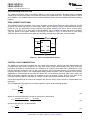
iL (t)
IL-MAX
ÂiL-PP
IL
IL-MIN
tON = DTS
tOFF = (1-D)TS
t
0
TS
Figure 15. Ideal CCM Regulator Inductor Current iL(t)
CURRENT REGULATORS
Current regulators can be designed to accomplish three basic functions: buck, boost, and buck-boost. All three
topologies in their most basic form contain a main switching MosFET, a recirculating diode, an inductor and
capacitors. The LM3421/23 is designed to drive a ground referenced NFET which is perfect for a standard boost
regulator. Buck and buck-boost regulators, on the other hand, usually have a high-side switch. When driving an
LED load, a ground referenced load is often not necessary, therefore a ground referenced switch can be used to
drive a floating load instead. The LM3421/23 can then be used to drive all three basic topologies as shown in the
Basic Topology Schematics section. Other topologies such as the SEPIC and flyback converter (both derivatives
of the buck-boost) can be implemented as well.
Looking at the buck-boost design, the basic operation of a current regulator can be analyzed. During the time
that the NFET (Q1) is turned on (tON), the input voltage source stores energy in the inductor (L1) while the output
capacitor (CO) provides energy to the LED load. When Q1 is turned off (tOFF), the re-circulating diode (D1)
becomes forward biased and L1 provides energy to both CO and the LED load. Figure 15 shows the inductor
current (iL(t)) waveform for a regulator operating in CCM.
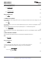
The average output LED current (ILED) is proportional to the average inductor current (IL) , therefore if IL is tightly
controlled, ILED will be well regulated. As the system changes input voltage or output voltage, the ideal duty cycle
(D) is varied to regulate IL and ultimately ILED. For any current regulator, D is a function of the conversion ratio:
Buck
D=
VO
VIN
(1)
VO - VIN
VO
(2)
Boost
D=
Buck-boost
D=
VO
VO + VIN
(3)
Copyright © 2008–2013, Texas Instruments Incorporated
Submit Documentation Feedback
Product Folder Links: LM3421 LM3421-Q1 LM3423 LM3423-Q1
11
LM3421, LM3421-Q1
LM3423, LM3423-Q1
SNVS574E – JULY 2008 – REVISED MAY 2013
www.ti.com
PREDICTIVE OFF-TIME (PRO) CONTROL
PRO control is used by the LM3421/23 to control ILED. It is a combination of average peak current control and a
one-shot off-timer that varies with input voltage. The LM3421/23 uses peak current control to regulate the
average LED current through an array of HBLEDs. This method of control uses a series resistor in the LED path
to sense LED current and can use either a series resistor in the MosFET path or the MosFET RDS-ON for both
cycle-by-cycle current limit and input voltage feed forward. D is indirectly controlled by changes in both tOFF and
tON, which vary depending on the operating point.
Even though the off-time control is quasi-hysteretic, the input voltage proportionality in the off-timer creates an
essentially constant switching frequency over the entire operating range for boost and buck-boost topologies.
The buck topology can be designed to give constant ripple over either input voltage or output voltage, however
switching frequency is only constant at a specific operating point .
This type of control minimizes the control loop compensation necessary in many switching regulators, simplifying
the design process. The averaging mechanism in the peak detection control loop provides extremely accurate
LED current regulation over the entire operating range.
PRO control was designed to mitigate “current mode instability” (also called “sub-harmonic oscillation”) found in
standard peak current mode control when operating near or above 50% duty cycles. When using standard peak
current mode control with a fixed switching frequency, this condition is present, regardless of the topology.
However, using a constant off-time approach, current mode instability cannot occur, enabling easier design and
control.
Predictive off-time advantages:
• There is no current mode instability at any duty cycle.
• Higher duty cycles / voltage transformation ratios are possible, especially in the boost regulator.
The only disadvantage is that synchronization to an external reference frequency is generally not available.
SWITCHING FREQUENCY
An external resistor (RT) connected between the RCT pin and the switch node (where D1, Q1, and L1 connect),
in combination with a capacitor (CT) between the RCT and AGND pins, sets the off-time (tOFF) as shown in
Figure 16. For boost and buck-boost topologies, the VIN proportionality ensures a virtually constant switching
frequency (fSW).
For a buck topology, RT and CT are also used to set tOFF, however the VIN proportionality will not ensure a
constant switching frequency. Instead, constant ripple operation can be achieved. Changing the connection of RT
in Figure 16 from VSW to VIN will provide a constant ripple over varying VIN. Adding a PNP transistor as shown in
Figure 17 will provide constant ripple over varying VO.
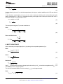
The switching frequency is defined:
Buck (Constant Ripple vs. VIN)
fSW =
25 x ( VIN - VO )
RT x CT X VIN
(4)
Buck (Constant Ripple vs. VO)
25 x (VIN x VO - VO )
2
fSW =
2
RT x C T x VIN
(5)
Boost and Buck-boost
25
fSW =
R T x CT
(6)
For all topologies, the CT capacitor is recommended to be 1 nF and should be located very close to the
LM3421/23.
12
Submit Documentation Feedback
Copyright © 2008–2013, Texas Instruments Incorporated
Product Folder Links: LM3421 LM3421-Q1 LM3423 LM3423-Q1
LM3421, LM3421-Q1
LM3423, LM3423-Q1
www.ti.com
SNVS574E – JULY 2008 – REVISED MAY 2013
VIN
VSW
LM3421/23
RSNS
VIN/25
RT
Start tON
RCT
RT
LM3421/23
CT
VIN/25
Reset timer
LED-
Start tON
RCT
CT
Reset timer
Figure 16. Off-timer Circuitry for Boost and Buckboost Regulators
Figure 17. Off-timer Circuitry for Buck Regulators
LM3421/23
ILED
VSNS
RHSP
RSNS
RHSN
RCSH
HSP
High-Side
Sense Amplifier
HSN
CSH
ICSH
Error Amplifier
To PWM
Comparator
1.24V
CCMP
COMP
Figure 18. LED Current Sense Circuitry
AVERAGE LED CURRENT
The LM3421/23 uses an external current sense resistor (RSNS) placed in series with the LED load to convert the
LED current (ILED) into a voltage (VSNS) as shown in Figure 18. The HSP and HSN pins are the inputs to the
high-side sense amplifier which are forced to be equal potential (VHSP=VHSN) through negative feedback.
Because of this, the VSNS voltage is forced across RHSP to generate the signal current (ICSH) which flows out of
the CSH pin and through the RCSH resistor. The error amplifier will regulate the CSH pin to 1.24V, therefore ICSH
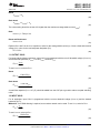
can be calculated:
ICSH =
VSNS
RHSP
(7)
This means VSNS will be regulated as follows:
RHSP
VSNS = 1.24V x
RCSH
(8)
ILED can then be calculated:
VSNS
1.24V RHSP
x
ILED =
=
RSNS
RSNS
RCSH
(9)
Copyright © 2008–2013, Texas Instruments Incorporated
Submit Documentation Feedback
Product Folder Links: LM3421 LM3421-Q1 LM3423 LM3423-Q1
13
LM3421, LM3421-Q1
LM3423, LM3423-Q1
SNVS574E – JULY 2008 – REVISED MAY 2013
www.ti.com
The selection of the three resistors (RSNS, RCSH, and RHSP) is not arbitrary. For matching and noise performance,
the suggested signal current ICSH is approximately 100 µA. This current does not flow in the LEDs and will not
affect either the off-state LED current or the regulated LED current. ICSH can be above or below this value, but
the high-side amplifier offset characteristics may be affected slightly. In addition, to minimize the effect of the
high-side amplifier voltage offset on LED current accuracy, the minimum VSNS is suggested to be 50 mV. Finally,
a resistor (RHSN = RHSP) should be placed in series with the HSN pin to cancel out the effects of the input bias
current (~10 µA) of both inputs of the high-side sense amplifier.
The sense resistor (RSNS) can be placed anywhere in the series string of LEDs as long as the voltage at the HSN
and HSP pins (VHSP and VHSN) satisfies the following conditions.
VHSP < 76V
VHSN > 3.5V
(10)
Typically, for a buck-boost configuration, RSNS is placed at the bottom of the string (LED-) which allows for
greater flexibility of input and output voltage. However, if there is substantial input voltage ripple allowed, it can
help to place RSNS at the top of the string (LED+) which limits the output voltage of the string to:
VO = 76V - VIN
(11)
Note that he CSH pin can also be used as a low-side current sense input regulated to 1.24V. The high-side
sense amplifier is disabled if HSP and HSN are tied to AGND (or VHSN > VHSP) .
ANALOG DIMMING
The CSH pin can be used to analog dim the LED current by adjusting the current sense voltage (VSNS). There
are several different methods to adjust VSNS using the CSH pin:
1. External variable resistance : Adjust a potentiometer placed in series with RCSH to vary VSNS.
2. External variable current source: Source current (0 µA to ICSH) into the CSH pin to adjust VSNS.
Variable Current Source
VCC
LM3421/23
VREF
Q8
Q7
RMAX
Q6
RADJ
RBIAS
CSH
RCSH
RADJ
Variable
Resistance
Figure 19. Analog Dimming Circuitry
In general, analog dimming applications require a lower switching frequency to minimize the effect of the leading
edge blanking circuit. As the LED current is reduced, the output voltage and the duty cycle decreases.
Eventually, the minimum on-time is reached. The lower the switching frequency, the wider the linear dimming
range. Figure 19 shows how both CSH methods are physically implemented.
Method 1 uses an external potentiometer in the CSH path which is a simple addition to the existing circuitry.
However, the LEDs cannot dim completely because there is always some resistance causing signal current to
flow. This method is also susceptible to noise coupling at the CSH pin since the potentiometer increases the size
of the signal current loop.
14
Submit Documentation Feedback
Copyright © 2008–2013, Texas Instruments Incorporated
Product Folder Links: LM3421 LM3421-Q1 LM3423 LM3423-Q1
LM3421, LM3421-Q1
LM3423, LM3423-Q1
www.ti.com
SNVS574E – JULY 2008 – REVISED MAY 2013
Method 2 provides a complete dimming range and better noise performance, though it is more complex. It
consists of a PNP current mirror and a bias network consisting of an NPN, 2 resistors and a potentiometer
(RADJ), where RADJ controls the amount of current sourced into the CSH pin. A higher resistance value will source
more current into the CSH pin causing less regulated signal current through RHSP, effectively dimming the LEDs.
VREF should be a precise external voltage reference, while Q7 and Q8 should be a dual pair PNP for best
matching and performance. The additional current (IADD) sourced into the CSH pin can be calculated:
IADD =
§ RADJ x VREF ·
¨R + R ¸ - VBE-Q6
© ADJ MAX ¹
RBIAS
(12)
The corresponding ILED for a specific IADD is:
§ RHSP·
¸
© RSNS¹
ILED = (ICSH - IADD) x ¨
(13)
CURRENT SENSE/CURRENT LIMIT
The LM3421/23 achieves peak current mode control using a comparator that monitors the main MosFET (Q1)
transistor current, comparing it with the COMP pin voltage as shown in Figure 20. Further, it incorporates a
cycle-by-cycle over-current protection function. Current limit is accomplished by a redundant internal current
sense comparator. If the voltage at the current sense comparator input (IS) exceeds 245 mV (typical), the on
cycle is immediately terminated. The IS input pin has an internal N-channel MosFET which pulls it down at the
conclusion of every cycle. The discharge device remains on an additional 210 ns (typical) after the beginning of a
new cycle to blank the leading edge spike on the current sense signal. The leading edge blanking (LEB)
determines the minimum achievable on-time (tON-MIN).
RDS-ON
Sensing
Q1
LM3421/23
COMP
GATE
0.8V
RLIM
Sensing
PWM
IS
0.245V
IT
RLIM
LEB
PGND
Figure 20. Current Sense / Current Limit Circuitry
There are two possible methods to sense the transistor current. The RDS-ON of the main power MosFET can be
used as the current sense resistance because the IS pin was designed to withstand the high voltages present on
the drain when the MosFET is in the off state. Alternatively, a sense resistor located in the source of the MosFET
may be used for current sensing, however a low inductance (ESL) type is suggested. The cycle-by-cycle current
limit (ILIM) can be calculated using either method as the limiting resistance (RLIM):
245 mV
ILIM =
RLIM
(14)
Copyright © 2008–2013, Texas Instruments Incorporated
Submit Documentation Feedback
Product Folder Links: LM3421 LM3421-Q1 LM3423 LM3423-Q1
15
LM3421, LM3421-Q1
LM3423, LM3423-Q1
SNVS574E – JULY 2008 – REVISED MAY 2013
www.ti.com
OVER-CURRENT PROTECTION
The LM3421/23 devices have a secondary method of over-current protection. Switching action is disabled
whenever the current in the LEDs is more than 30% above the regulation set point. The dimming MosFET switch
driver (DDRV) is not disabled however as this would immediately remove the fault condition and cause oscillatory
behavior.
ZERO CURRENT SHUTDOWN
The LM3421/23 devices implement "zero current" shutdown via the EN and RPD pins. When pulled low, the EN
pin places the devices into near-zero current state, where only the leakage currents will be observed at the pins
(typical 0.1 µA). The applications circuits, frequently have resistor dividers to set UVLO, OVLO, or other similar
functions. The RPD pin is an open drain N-channel MosFET that is enabled only when the device is enabled.
Tying the bottom of all resistor dividers to the RPD pin as shown in Figure 21 allows them to float during
shutdown, thus removing their current paths and providing true application-wide zero current shutdown.
L1
D1
VIN
VO
Enable
LM3421/23
EN
ROV2
VIN
OVP
nDIM
RPD
ROV1
RUV2
RUV1
Figure 21. Zero Current Shutdown Circuit
CONTROL LOOP COMPENSATION
The LM3421/23 control loop is modeled like any current mode controller. Using a first order approximation, the
uncompensated loop can be modeled as a single pole created by the output capacitor and, in the boost and
buck-boost topologies, a right half plane zero created by the inductor, where both have a dependence on the
LED string dynamic resistance. There is also a high frequency pole in the model, however it is near the switching
frequency and plays no part in the compensation design process therefore it will be neglected. Since ceramic
capacitance is recommended for use with LED drivers due to long lifetimes and high ripple current rating, the
ESR of the output capacitor can also be neglected in the loop analysis. Finally, there is a DC gain of the
uncompensated loop which is dependent on internal controller gains and the external sensing network.
A buck-boost regulator will be used as an example case. See the Design Guide section for compensation of all
topologies.
The uncompensated loop gain for a buck-boost regulator is given by the following equation:
§
s ·
¸
¨1 ¨ ZZ1 ¸
¹
©
TU = TU0 x
§
s ·
¨1+
¸
¨ ZP1 ¸
©
¹
(15)
Where the uncompensated DC loop gain of the system is described as:
Dc x 500V x RCSH x RSNS
Dc x 620V
TU0 =
=
(1+ D) x RHSP x R LIM (1+ D) x ILED x R LIM
(16)
And the output
3 pole (ωP1) is approximated:
1+ D
ZP1 =
rD x CO
(17)
16
Submit Documentation Feedback
Copyright © 2008–2013, Texas Instruments Incorporated
Product Folder Links: LM3421 LM3421-Q1 LM3423 LM3423-Q1
LM3421, LM3421-Q1
LM3423, LM3423-Q1
www.ti.com
SNVS574E – JULY 2008 – REVISED MAY 2013
And the right half plane zero (ωZ1) is:
rD x Dc2
ZZ1 =
D x L1
(18)
100
öZ1
80
135
öP1
90
GAIN
GAIN (dB)
0
40
PHASE
-45
20
0° Phase Margin
-90
0
-20
-135
-40
-180
-60
1e-1
PHASE (°)
45
60
1e1
1e3
1e5
-225
1e7
FREQUENCY (Hz)
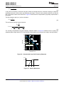
Figure 22. Uncompensated Loop Gain Frequency Response
Figure 22 shows the uncompensated loop gain in a worst-case scenario when the RHP zero is below the output
pole. This occurs at high duty cycles when the regulator is trying to boost the output voltage significantly. The
RHP zero adds 20dB/decade of gain while loosing 45°/decade of phase which places the crossover frequency
(when the gain is zero dB) extremely high because the gain only starts falling again due to the high frequency
pole (not modeled or shown in figure). The phase will be below -180° at the crossover frequency which means
there is no phase margin (180° + phase at crossover frequency) causing system instability. Even if the output
pole is below the RHP zero, the phase will still reach -180° before the crossover frequency in most cases yielding
instability.
LM3421/23
ILED
RHSP
HSP
High-Side
Sense Amplifier
CFS
VSNS
RSNS
RHSN
HSN
RFS
sets öP3
RCSH
Error Amplifier
CSH
1.24V
sets öP2
CCMP
To PWM
Comparator
RO
COMP
Figure 23. Compensation Circuitry
To mitigate this problem, a compensator should be designed to give adequate phase margin (above 45°) at the
crossover frequency. A simple compensator using a single capacitor at the COMP pin (CCMP) will add a dominant
pole to the system, which will ensure adequate phase margin if placed low enough. At high duty cycles (as
shown in Figure 22), the RHP zero places extreme limits on the achievable bandwidth with this type of
compensation. However, because an LED driver is essentially free of output transients (except catastrophic
failures open or short), the dominant pole approach, even with reduced bandwidth, is usually the best approach.
The dominant compensation pole (ωP2) is determined by CCMP and the output resistance (RO) of the error
amplifier (typically 5 MΩ):
Copyright © 2008–2013, Texas Instruments Incorporated
Submit Documentation Feedback
Product Folder Links: LM3421 LM3421-Q1 LM3423 LM3423-Q1
17
LM3421, LM3421-Q1
LM3423, LM3423-Q1
SNVS574E – JULY 2008 – REVISED MAY 2013
ZP2 =
www.ti.com
1
5e6: x CCMP
(19)
It may also be necessary to add one final pole at least one decade above the crossover frequency to attenuate
switching noise and, in some cases, provide better gain margin. This pole can be placed across RSNS to filter the
ESL of the sense resistor at the same time. Figure 23 shows how the compensation is physically implemented in
the system.
The high frequency pole (ωP3) can be calculated:
1
ZP3 =
RFS x CFS
(20)
The total system transfer function becomes:
§ s ·
¨1 ¸
¨ ZZ1¸
©
¹
T = TU0 x
§
s · §
s · §
s ·
¸ ¨
¸ ¨
¨1+
¸
¨ ZP1¸ x ¨1+ ZP2¸ x ¨1+ ZP3¸
¹ ©
¹ ©
©
¹
(21)
The resulting compensated loop gain frequency response shown in Figure 24 indicates that the system has
adequate phase margin (above 45°) if the dominant compensation pole is placed low enough, ensuring stability:
90
80
öP2
45
60
20
0
0
GAIN
öZ1
-90
PHASE
öP3
-20
-40
-45
öP1
-135
60° Phase Margin
-180
-225
-60
-80
1e-1
PHASE (°)
GAIN (dB)
40
1e1
1e3
1e5
-270
1e7
FREQUENCY (Hz)
Figure 24. Compensated Loop Gain Frequency Response
VCMP
0.9V
0
tVCC
tCMP
tCO
t
Figure 25. Start-Up Waveforms
18
Submit Documentation Feedback
Copyright © 2008–2013, Texas Instruments Incorporated
Product Folder Links: LM3421 LM3421-Q1 LM3423 LM3423-Q1
LM3421, LM3421-Q1
LM3423, LM3423-Q1
www.ti.com
SNVS574E – JULY 2008 – REVISED MAY 2013
START-UP REGULATOR
The LM3421/23 includes a high voltage, low dropout bias regulator. When power is applied, the regulator is
enabled and sources current into an external capacitor (CBYP) connected to the VCC pin. The recommended
bypass capacitance for the VCC regulator is 2.2 µF to 3.3 µF. The output of the VCC regulator is monitored by an
internal UVLO circuit that protects the device from attempting to operate with insufficient supply voltage and the
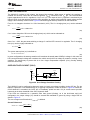
supply is also internally current limited. Figure 25 shows the typical start-up waveforms for the LM3421/23.
First, CBYP is charged to be above VCC UVLO threshold (~4.2V). The CVCC charging time (tVCC) can be estimated
as:
t VCC =
4.2V
x CBYP = 168: x CBYP
25 mA
(22)
CCMP is then charged to 0.9V over the charging time (tCMP) which can be estimated as:
t CMP =
0.9V
x CCMP = 36 k: x CCMP
25 PA
(23)
Once CCMP = 0.9V, the part starts switching to charge CO until the LED current is in regulation. The CO charging
time (tCO) can be roughly estimated as:
t CO = CO x
VO
ILED
(24)
The system start-up time (tSU) is defined as:
t SU = t VCC + t CMP + t CO
(25)
In some configurations, the start-up waveform will overshoot the steady state COMP pin voltage. In this case, the
LED current and output voltage will overshoot also, which can trip the over-voltage or protection, causing a race
condition. The easiest way to prevent this is to use a larger compensation capacitor (CCMP), thereby slowing
down the control loop.
OVER-VOLTAGE LOCKOUT (OVLO)
LM3421/23
VO
23 PA
ROV2
OVP
1.24V
OVLO
ROV1
Figure 26. Over-Voltage Protection Circuitry
The LM3421/23 can be configured to detect an output (or input) over-voltage condition via the OVP pin. The pin
features a precision 1.24V threshold with 23 µA (typical) of hysteresis current as shown in Figure 26. When the
OVLO threshold is exceeded, the GATE pin is immediately pulled low and a 23 µA current source provides
hysteresis to the lower threshold of the OVLO hysteretic band.
If the LEDs are referenced to a potential other than ground (floating), as in the buck-boost and buck
configuration, the output voltage (VO) should be sensed and translated to ground by using a single PNP as
shown in Figure 27.
The over-voltage turn-off threshold (VTURN-OFF) is defined:
Ground Referenced
§R + ROV 2·
¸
VTURN - OFF = 1.24V x ¨¨ OV1
¸
© R OV1 ¹
Copyright © 2008–2013, Texas Instruments Incorporated
(26)
Submit Documentation Feedback
Product Folder Links: LM3421 LM3421-Q1 LM3423 LM3423-Q1
19
LM3421, LM3421-Q1
LM3423, LM3423-Q1
SNVS574E – JULY 2008 – REVISED MAY 2013
www.ti.com
Floating
§0.5 x R OV1+ R OV2·
¸
VTURN - OFF = 1.24V x ¨¨
¸
R OV1
¹
©
(27)
In the ground referenced configuration, the voltage across ROV2 is VO - 1.24V whereas in the floating
configuration it is VO - 620 mV where 620 mV approximates VBE of the PNP.
The over-voltage hysteresis (VHYSO) is defined:
VHYSO = 23 PA x ROV2
(28)
LED+
ROV2
LM3421/23
LEDOVP
ROV1
Figure 27. Floating Output OVP Circuitry
The OVLO feature can cause some interesting results if the OVLO trip-point is set too cose to VO. At turn-on, the
converter has a modest amount of voltage overshoot before the control loop gains control of ILED. If the overshoot
exceeds the OVLO threshold, the controller shuts down, opening the dimming MosFET. This isolates the LED
load from the converter and the output capacitance. The voltage will then discharge very slowly through the HSP
and HSN pins until VO drops below the lower threshold, where the process repeats. This looks like the LEDs are
blinking at around 2 Hz. This mode can be escaped if the input voltage is reduced.
INPUT UNDER-VOLTAGE LOCKOUT (UVLO)
The nDIM pin is a dual-function input that features an accurate 1.24V threshold with programmable hysteresis as
shown in Figure 28. This pin functions as both the PWM dimming input for the LEDs and as a VIN UVLO. When
the pin voltage rises and exceeds the 1.24V threshold, 23 µA (typical) of current is driven out of the nDIM pin into
the resistor divider providing programmable hysteresis.
LM3421/23
VIN
23 PA
RUV2
RUV1
nDIM
RUVH
1.24V
UVLO
(optional)
Figure 28. UVLO Circuit
When using the nDIM pin for UVLO and PWM dimming concurrently, the UVLO circuit can have an extra series
resistor to set the hysteresis. This allows the standard resistor divider to have smaller resistor values minimizing
PWM delays due to a pull-down MosFET at the nDIM pin (see PWM DIMMING section). In general, at least 3V
of hysteresis is preferable when PWM dimming, if operating near the UVLO threshold.
The turn-on threshold (VTURN-ON) is defined as follows:
20
Submit Documentation Feedback
Copyright © 2008–2013, Texas Instruments Incorporated
Product Folder Links: LM3421 LM3421-Q1 LM3423 LM3423-Q1
LM3421, LM3421-Q1
LM3423, LM3423-Q1
www.ti.com
VTURN
SNVS574E – JULY 2008 – REVISED MAY 2013
ON
-
§R + RUV2·
¸
= 1.24V x ¨¨ UV1
¸
© RUV1 ¹
(29)
The hysteresis (VHYS) is defined as follows:
UVLO only
VHYS = 23 PA x RUV2
(30)
PWM dimming and UVLO
§
R x (RUV1 + RUV2)·
¸
VHYS = 23 PA x ¨¨RUV2 + UVH
¸
RUV1
¹
©
(31)
When "zero current" shutdown and UVLO are implemented together, the EN pin can be used to escape UVLO.
The nDIM pin will pull-up to VIN when EN is pulled low, therefore if VIN is within the UVLO hysteretic window
when EN is pulled high again, the controller will start-up even though VTURN-ON is not exceeded.
PWM DIMMING
The active low nDIM pin can be driven with a PWM signal which controls the main NFET and the dimming FET
(dimFET). The brightness of the LEDs can be varied by modulating the duty cycle of this signal. LED brightness
is approximately proportional to the PWM signal duty cycle, (i.e. 30% duty cycle ~ 30% LED brightness). This
function can be ignored if PWM dimming is not required by using nDIM solely as a VIN UVLO input as described
in the INPUT UNDER-VOLTAGE LOCKOUT (UVLO) section or by tying it directly to VCC or VIN.
Inverted
PWM
VIN
LM3421/23
DDIM
RUV2
RUVH
RUV1
nDIM
QDIM
Standard
PWM
Figure 29. PWM Dimming Circuit
Figure 29 shows how the PWM signal is applied to nDIM:
1. Connect the dimming MosFET (QDIM) with the drain to the nDIM pin and the source to AGND. Apply an
external logic-level PWM signal to the gate of QDIM.
2. Connect the anode of a Schottky diode (DDIM) to the nDIM pin. Apply an inverted external logic-level PWM
signal to the cathode of the same diode.
The DDRV pin is a PWM output that follows the nDIM PWM input signal. When the nDIM pin rises, the DDRV pin
rises and the PWM latch reset signal is removed allowing the main MosFET Q1 to turn on at the beginning of the
next clock set pulse. In boost and buck-boost topologies, the DDRV pin is used to control a N-channel MosFET
placed in series with the LED load, while it would control a P-channel MosFET in parallel with the load for a buck
topology.
Copyright © 2008–2013, Texas Instruments Incorporated
Submit Documentation Feedback
Product Folder Links: LM3421 LM3421-Q1 LM3423 LM3423-Q1
21
LM3421, LM3421-Q1
LM3423, LM3423-Q1
SNVS574E – JULY 2008 – REVISED MAY 2013
www.ti.com
The series dimFET will open the LED load, when nDIM is low, effectively speeding up the rise and fall times of
the LED current. Without any dimFET, the rise and fall times are limited by the inductor slew rate and dimming
frequencies above 1 kHz are impractical. Using the series dimFET, dimming frequencies up to 30 kHz are
achievable. With a parallel dimFET (buck topology), even higher dimming frequencies are achievable.
When using the PWM functionality in a boost regulator, the PWM signal can drive a ground referenced FET.
However, with buck-boost and buck topologies, level shifting circuitry is necessary to translate the PWM dim
signal to the floating dimFET as shown in Figure 30 and Figure 31. If high side dimming is necessary in a boost
regulator using the LM3423, level shifting can be added providing the polarity inverting DPOL pin is pulled low
(see LM3423 ONLY: DPOL, FLT, TIMR, and LRDY section) as shown in Figure 32.
When using a series dimFET to PWM dim the LED current, more output capacitance is always better. A general
rule of thumb is to use a minimum of 40 µF when PWM dimming. For most applications, this will provide
adequate energy storage at the output when the dimFET turns off and opens the LED load. Then when the
dimFET is turned back on, the capacitance helps source current into the load, improving the LED current rise
time.
A minimum on-time must be maintained in order for PWM dimming to operate in the linear region of its transfer
function. Because the controller is disabled during dimming, the PWM pulse must be long enough such that the
energy intercepted from the input is greater than or equal to the energy being put into the LEDs. For boost and
buck-boost regulators, the minimum dimming pulse length in seconds (tPULSE) is:
2 x ILED x VO X L1
tPULSE =
VIN2
(32)
Even maintaining a dimming pulse greater than tPULSE, preserving linearity at low dimming duty cycles is difficult.
The second helpful modification is to remove the CFS capacitor and RFS resistor, eliminating the high frequency
compensation pole. This should not affect stability, but it will speed up the response of the CSH pin, specifically
at the rising edge of the LED current when PWM dimming, thus improving the achievable linearity at low dimming
duty cycles.
LED+
LM3421/23
10:
5 k:
Q7
100 nF
Q2
VCC
Q6
Q4
RSNS
10V
500:
100 pF
VIN
DDRV
Figure 30. Buck-boost Level-Shifted PWM Circuit
22
Submit Documentation Feedback
Copyright © 2008–2013, Texas Instruments Incorporated
Product Folder Links: LM3421 LM3421-Q1 LM3423 LM3423-Q1
LM3421, LM3421-Q1
LM3423, LM3423-Q1
www.ti.com
SNVS574E – JULY 2008 – REVISED MAY 2013
LM3421/23
RSNS
100
k:
10V
Q2
100 nF
DDRV
Figure 31. Buck Level-Shifted PWM Circuit
VO
LM3421/23
RSNS
DPOL
100
k:
10V
Q2
VCC
Q6
100 pF
10 k:
DDRV
Figure 32. Boost Level-Shifted PWM Circuit
LM3423 ONLY: DPOL, FLT, TIMR, and LRDY
The LM3423 has four additional pins: DPOL, FLT, TIMR, and LRDY. The DPOL pin is simply used to invert the
DDRV polarity . If DPOL is left open, then it is internally pulled high and the polarity is correct for driving a series
N-channel dimFET. If DPOL is pulled low then the polarity is correct for using a series P-channel dimFET in highside dimming applications. For a parallel P-channel dimFET, as used in the buck topology, leave DPOL open for
proper polarity.
Among the LM3423's other additional pins are TIMR and FLT which can be used in conjunction with an input
disconnect MosFET switch as shown in Figure 33 to protect the module from various fault conditions.
A fault is detected and an 11.5 µA (typical) current is sourced from the TIMR pin whenever any of the following
conditions exist:
1. LED current is above regulation by more than 30%.
2. OVLO has engaged.
3. Thermal shutdown has engaged.
An external capacitor (CTMR) from TIMR to AGND programs the fault filter time as follows:
t FLT x 11.5 PA
CTMR =
1.24V
(33)
When the voltage on the TIMR pin reaches 1.24V, the device is latched off and the N-channel MosFET open
drain FLT pin transitions to a high impedance state. The TIMR pin will be immediately pulled to ground (reset) if
the fault condition is removed at any point during the filter period. Otherwise, if the timer expires, the fault will
remain latched until one of three things occurs:
Copyright © 2008–2013, Texas Instruments Incorporated
Submit Documentation Feedback
Product Folder Links: LM3421 LM3421-Q1 LM3423 LM3423-Q1
23
LM3421, LM3421-Q1
LM3423, LM3423-Q1
SNVS574E – JULY 2008 – REVISED MAY 2013
www.ti.com
1. The EN pin is pulled low long enough for the VCC pin to drop below 4.1V (approximately 200 ms).
2. The TIMR pin is pulled to ground.
3. A complete power cycle occurs.
When using the EN and OVP pins in conjunction with the RPD pull-down pin, a race condition exists when
exiting the disabled (EN low) state. When disabled, the OVP pin is pulled up to the output voltage because the
RPD pull-down is disabled, and this will appear to be a real OVLO condition. The timer pin will immediately rise
and latch the controller to the fault state. To protect against this behavior, a minimum timer capacitor (CTMR =
220pF) should be used. If fault latching is not required, short the TMR pin to AGND which will disable the FLT
flag function.
The LM3423 also includes an LED Ready (LRDY) flag to notify the system that the LEDs are in proper
regulation. The N-channel MosFET open drain LRDY pin is pulled low whenever any of the following conditions
are met:
1. VCC UVLO has engaged.
2. LED current is below regulation by more than 20%.
3. LED current is above regulation by more than 30%.
4. Over-voltage protection has engaged
5. Thermal shutdown has engaged.
6. A fault has latched the device off.
Note that the LRDY pin is pulled low during startup of the device and remains low until the LED current is in
regulation.
VIN
VSW
LM3421/23
FLT
VIN
High = LED in regulation
LRDY
TIMR
Figure 33. Fault Detection and LED Status Circuit
Design Considerations
This section describes the application level considerations when designing with the LM3421/23. For
corresponding calculations, refer to the Design Guide section.
INDUCTOR
The inductor (L1) is the main energy storage device in a switching regulator. Depending on the topology, energy
is stored in the inductor and transfered to the load in different ways (as an example, buck-boost operation is
detailed in the CURRENT REGULATORS section). The size of the inductor, the voltage across it, and the length
of the switching subinterval (tON or tOFF) determines the inductor current ripple (ΔiL-PP ). In the design process, L1
is chosen to provide a desired ΔiL-PP. For a buck regulator the inductor has a direct connection to the load, which
is good for a current regulator. This requires little to no output capacitance therefore ΔiL-PP is basically equal to
the LED ripple current ΔiLED-PP. However, for boost and buck-boost regulators, there is always an output
capacitor which reduces ΔiLED-PP, therefore the inductor ripple can be larger than in the buck regulator case
where output capacitance is minimal or completely absent.
24
Submit Documentation Feedback
Copyright © 2008–2013, Texas Instruments Incorporated
Product Folder Links: LM3421 LM3421-Q1 LM3423 LM3423-Q1
LM3421, LM3421-Q1
LM3423, LM3423-Q1
www.ti.com
SNVS574E – JULY 2008 – REVISED MAY 2013
In general, ΔiLED-PP is recommended by manufacturers to be less than 40% of the average LED current (ILED).
Therefore, for the buck regulator with no output capacitance, ΔiL-PP should also be less than 40% of ILED. For the
boost and buck-boost topologies, ΔiL-PP can be much higher depending on the output capacitance value.
However, ΔiL-PP is suggested to be less than 100% of the average inductor current (IL) to limit the RMS inductor
current.
L1 is also suggested to have an RMS current rating at least 25% higher than the calculated minimum allowable
RMS inductor current (IL-RMS).
LED DYNAMIC RESISTANCE
When the load is a string of LEDs, the output load resistance is the LED string dynamic resistance plus RSNS.
LEDs are PN junction diodes, and their dynamic resistance shifts as their forward current changes. Dividing the
forward voltage of a single LED (VLED) by the forward current (ILED) leads to an incorrect calculation of the
dynamic resistance of a single LED (rLED). The result can be 5 to 10 times higher than the true rLED value.
Figure 34. Dynamic Resistance
Obtaining rLED is accomplished by refering to the manufacturer's LED I-V characteristic. It can be calculated as
the slope at the nominal operating point as shown in Figure 34. For any application with more than 2 series
LEDs, RSNS can be neglected allowing rD to be approximated as the number of LEDs multiplied by rLED.
OUTPUT CAPACITOR
For boost and buck-boost regulators, the output capacitor (CO) provides energy to the load when the recirculating
diode (D1) is reverse biased during the first switching subinterval. An output capacitor in a buck topology will
simply reduce the LED current ripple (ΔiLED-PP) below the inductor current ripple (ΔiL-PP). In all cases, CO is sized
to provide a desired ΔiLED-PP. As mentioned in the INDUCTOR section, ΔiLED-PP is recommended by
manufacturers to be less than 40% of the average LED current (ILED-PP).
CO should be carefully chosen to account for derating due to temperature and operating voltage. It must also
have the necessary RMS current rating. Ceramic capacitors are the best choice due to their high ripple current
rating, long lifetime, and good temperature performance. An X7R dieletric rating is suggested.
INPUT CAPACITORS
The input capacitance (CIN) provides energy during the discontinuous portions of the switching period. For buck
and buck-boost regulators, CIN provides energy during tON and during tOFF, the input voltage source charges up
CIN with the average input current (IIN). For boost regulators, CIN only needs to provide the ripple current due to
the direct connection to the inductor. CIN is selected given the maximum input voltage ripple (ΔvIN-PP) which can
be tolerated. ΔvIN-PP is suggested to be less than 10% of the input voltage (VIN).
An input capacitance at least 100% greater than the calculated CIN value is recommended to account for derating
due to temperature and operating voltage. When PWM dimming, even more capacitance can be helpful to
minimize the large current draw from the input voltage source during the rising transistion of the LED current
waveform.
Copyright © 2008–2013, Texas Instruments Incorporated
Submit Documentation Feedback
Product Folder Links: LM3421 LM3421-Q1 LM3423 LM3423-Q1
25
LM3421, LM3421-Q1
LM3423, LM3423-Q1
SNVS574E – JULY 2008 – REVISED MAY 2013
www.ti.com
The chosen input capacitors must also have the necessary RMS current rating. Ceramic capacitors are again the
best choice due to their high ripple current rating, long lifetime, and good temperature performance. An X7R
dieletric rating is suggested.
For most applications, it is recommended to bypass the VIN pin with an 0.1 µF ceramic capacitor placed as close
as possible to the pin. In situations where the bulk input capacitance may be far from the LM3421/23 device, a
10 Ω series resistor can be placed between the bulk input capacitance and the bypass capacitor, creating a
150 kHz filter to eliminate undesired high frequency noise.
MAIN MosFET / DIMMING MosFET
The LM3421/23 requires an external NFET (Q1) as the main power MosFET for the switching regulator. Q1 is
recommended to have a voltage rating at least 15% higher than the maximum transistor voltage to ensure safe
operation during the ringing of the switch node. In practice, all switching regulators have some ringing at the
switch node due to the diode parasitic capacitance and the lead inductance. The current rating is recommended
to be at least 10% higher than the average transistor current. The power rating is then verified by calculating the
power loss given the RMS transistor current and the NFET on-resistance (RDS-ON).
When PWM dimming, the LM3421/23 requires another MosFET (Q2) placed in series (or parallel for a buck
regulator) with the LED load. This MosFET should have a voltage rating equal to the output voltage (VO) and a
current rating at least 10% higher than the nominal LED current (ILED) . The power rating is simply VO multiplied
by ILED, assuming 100% dimming duty cycle (continuous operation) will occur.
In general, the NFETs should be chosen to minimize total gate charge (Qg) when fSW is high and minimize RDS-ON
otherwise. This will minimize the dominant power losses in the system. Frequently, higher current NFETs in
larger packages are chosen for better thermal performance.
RE-CIRCULATING DIODE
A re-circulating diode (D1) is required to carry the inductor current during tOFF. The most efficient choice for D1 is
a Schottky diode due to low forward voltage drop and near-zero reverse recovery time. Similar to Q1, D1 is
recommended to have a voltage rating at least 15% higher than the maximum transistor voltage to ensure safe
operation during the ringing of the switch node and a current rating at least 10% higher than the average diode
current. The power rating is verified by calculating the power loss through the diode. This is accomplished by
checking the typical diode forward voltage from the I-V curve on the product datasheet and multiplying by the
average diode current. In general, higher current diodes have a lower forward voltage and come in better
performing packages minimizing both power losses and temperature rise.
BOOST INRUSH CURRENT
When configured as a boost converter, there is a “phantom” power path comprised of the inductor, the output
diode, and the output capacitor. This path will cause two things to happen when power is applied. First, there will
be a very large inrush of current to charge the output capacitor. Second, the energy stored in the inductor during
this inrush will end up in the output capacitor, charging it to a higher potential than the input voltage.
Depending on the state of the EN pin, the output capacitor would be discharged by:
1. EN < 1.3V: no discharge path (leakage only).
2. EN > 1.3V, the OVP divider resistor path, if present, and 10µA into each of the HSP & HSN pins.
In applications using the OVP divider and with EN > 1.3V, the output capacitor voltage can charge higher than
VTURN-OFF. In this situation, the FLT pin (LM3423 only) is open and the PWM dimming MosFET is turned off. This
condition (the system appearing disabled) can persist for an undesirably long time. Possible solutions to this
condition are:
• Add an inrush diode from VIN to the output as shown in Figure 35.
• Add an NTC thermistor in series with the input to prevent the inrush from overcharging the output capacitor
too high.
• Use a current limited source supply.
• Raise the OVP threshold.
26
Submit Documentation Feedback
Copyright © 2008–2013, Texas Instruments Incorporated
Product Folder Links: LM3421 LM3421-Q1 LM3423 LM3423-Q1
LM3421, LM3421-Q1
LM3423, LM3423-Q1
www.ti.com
SNVS574E – JULY 2008 – REVISED MAY 2013
Boost Inrush Diode
L1
D1
VIN
VO
Q1
Figure 35. Boost Topology with Inrush Diode
CIRCUIT LAYOUT
The performance of any switching regulator depends as much upon the layout of the PCB as the component
selection. Following a few simple guidelines will maximimize noise rejection and minimize the generation of EMI
within the circuit.
Discontinuous currents are the most likely to generate EMI, therefore care should be taken when routing these
paths. The main path for discontinuous current in the LM3421/23 buck regulator contains the input capacitor
(CIN), the recirculating diode (D1), the N-channel MosFET (Q1), and the sense resistor (RLIM). In the LM3421/23
boost regulator, the discontinuous current flows through the output capacitor (CO), D1, Q1, and RLIM. In the buckboost regulator both loops are discontinuous and should be carefully layed out. These loops should be kept as
small as possible and the connections between all the components should be short and thick to minimize
parasitic inductance. In particular, the switch node (where L1, D1 and Q1 connect) should be just large enough
to connect the components. To minimize excessive heating, large copper pours can be placed adjacent to the
short current path of the switch node.
The RT, COMP, CSH, IS, HSP and HSN pins are all high-impedance inputs which couple external noise easily,
therefore the loops containing these nodes should be minimized whenever possible.
In some applications the LED or LED array can be far away (several inches or more) from the LM3421/23, or on
a separate PCB connected by a wiring harness. When an output capacitor is used and the LED array is large or
separated from the rest of the regulator, the output capacitor should be placed close to the LEDs to reduce the
effects of parasitic inductance on the AC impedance of the capacitor.
Copyright © 2008–2013, Texas Instruments Incorporated
Submit Documentation Feedback
Product Folder Links: LM3421 LM3421-Q1 LM3423 LM3423-Q1
27
LM3421, LM3421-Q1
LM3423, LM3423-Q1
SNVS574E – JULY 2008 – REVISED MAY 2013
www.ti.com
Basic Topology Schematics
BOOST REGULATOR (VIN < VO)
L1
D1
VIN
1
CIN
2
VIN
LM3421
HSN
HSP
EN
16
RHSN
15
RHSP
CFS
RSNS
RFS
RT
CCMP
RCSH
3
4
5
COMP
RPD
CSH
IS
RCT
VCC
14
13
CO
ROV2
COV
ROV1
ILED
12
CBYP
CT
6
AGND
GATE
OVP
PGND
11
Q1
RUV2
7
10
RLIM
DAP
RUVH
RUV1
28
Q3
8
nDIM
DDRV
9
Q2
PWM
Submit Documentation Feedback
Copyright © 2008–2013, Texas Instruments Incorporated
Product Folder Links: LM3421 LM3421-Q1 LM3423 LM3423-Q1
LM3421, LM3421-Q1
LM3423, LM3423-Q1
www.ti.com
SNVS574E – JULY 2008 – REVISED MAY 2013
BUCK REGULATOR (VIN > VO)
VIN
1
CIN
2
VIN
LM3421
HSN
HSP
EN
16
RHSN
15
RHSP
CFS
RSNS
RFS
RT
CCMP
3
COMP
RPD
CO
14
RPU
RCSH
4
CSH
IS
D2
13
Q2
DIM
5
RCT
VCC
ROV2
ILED
D1
12
L1
CBYP
CT
6
AGND
GATE
OVP
PGND
Q5
11
Q1
RUV2
7
10
RLIM
DAP
RUVH
8
nDIM
DDRV
9
DIM
CDIM
RUV1
Q3
PWM
COV
Copyright © 2008–2013, Texas Instruments Incorporated
Submit Documentation Feedback
Product Folder Links: LM3421 LM3421-Q1 LM3423 LM3423-Q1
ROV1
29
LM3421, LM3421-Q1
LM3423, LM3423-Q1
SNVS574E – JULY 2008 – REVISED MAY 2013
www.ti.com
BUCK-BOOST REGULATOR
L1
D1
VIN
ILED
1
CIN
2
VIN
LM3421
HSN
HSP
EN
16
RHSN
15
RHSP
DIM
CO
Q2
CFS
RSNS
VIN
RFS
RT
CCMP
RCSH
3
4
COMP
RPD
CSH
IS
14
RPU
13
Q7
DIM
5
RCT
VCC
12
Q6
Q4
CBYP
CT
6
GATE
AGND
D2
11
ROV2
CG
Q5
Q1
VIN
RUV2
7
PGND
OVP
10
RLIM
RSER
DAP
RUVH
RUV1
30
Q3
8
nDIM
DDRV
9
PWM
COV
Submit Documentation Feedback
ROV1
Copyright © 2008–2013, Texas Instruments Incorporated
Product Folder Links: LM3421 LM3421-Q1 LM3423 LM3423-Q1
LM3421, LM3421-Q1
LM3423, LM3423-Q1
www.ti.com
SNVS574E – JULY 2008 – REVISED MAY 2013
Design Guide
Refer to the Basic Topology Schematics section.
SPECIFICATIONS
Number of series LEDs: N
Single LED forward voltage: VLED
Single LED dynamic resistance: rLED
Nominal input voltage: VIN
Input voltage range: VIN-MAX, VIN-MIN
Switching frequency: fSW
Current sense voltage: VSNS
Average LED current: ILED
Inductor current ripple: ΔiL-PP
LED current ripple: ΔiLED-PP
Peak current limit: ILIM
Input voltage ripple: ΔvIN-PP
Output OVLO characteristics: VTURN-OFF, VHYSO
Input UVLO characteristics: VTURN-ON, VHYS
1. OPERATING POINT
Given the number of series LEDs (N), the forward voltage (VLED) and dynamic resistance (rLED) for a single LED,
solve for the nominal output voltage (VO) and the nominal LED string dynamic resistance (rD):
VO = N x VLED
(34)
rD = N x rLED
(35)
Solve for the ideal nominal duty cycle (D):
Buck
D=
VO
VIN
(36)
VO - VIN
VO
(37)
Boost
D=
Buck-boost
D=
VO
VO + VIN
(38)
Using the same equations, find the minimum duty cycle (DMIN) using maximum input voltage (VIN-MAX) and the
maximum duty cycle (DMAX) using the minimum input voltage (VIN-MIN). Also, remember that D' = 1 - D.
2. SWITCHING FREQUENCY
Set the switching frequency (fSW) by assuming a CT value of 1 nF and solving for RT:
Copyright © 2008–2013, Texas Instruments Incorporated
Submit Documentation Feedback
Product Folder Links: LM3421 LM3421-Q1 LM3423 LM3423-Q1
31
LM3421, LM3421-Q1
LM3423, LM3423-Q1
SNVS574E – JULY 2008 – REVISED MAY 2013
www.ti.com
Buck (Constant Ripple vs. VIN)
RT =
25 x ( VIN - VO )
fSW x CT X VIN
(39)
2
RT =
25 x (VIN x VO - VO
fSW x C T x
)
2
VIN
(40)
Boost and Buck-boost
RT =
25
fSW x C T
(41)
3. AVERAGE LED CURRENT
For all topologies, set the average LED current (ILED) knowing the desired current sense voltage (VSNS) and
solving for RSNS:
VSNS
RSNS =
ILED
(42)
If the calculated RSNS is too far from a desired standard value, then VSNS will have to be adjusted to obtain a
standard value.
Setup the suggested signal current of 100 µA by assuming RCSH = 12.4 kΩ and solving for RHSP:
ILED x RCSH x RSNS
RHSP =
1.24V
(43)
If the calculated RHSP is too far from a desired standard value, then RCSH can be adjusted to obtain a standard
value.
4. INDUCTOR RIPPLE CURRENT
Set the nominal inductor ripple current (ΔiL-PP) by solving for the appropriate inductor (L1):
Buck
(V - V ) x D
L1 = üIN O
xf
i L - PP SW
(44)
Boost and Buck-boost
30
VIN x D
L1=
üiL- PP x fSW
(45)
To set the worst case inductor ripple current, use VIN-MAX and DMIN when solving for L1.
The minimum allowable inductor RMS current rating (IL-RMS) can be calculated as:
Buck
IL-RMS = ILED x
32
1 § 'IL-PP·
x
1+
¸
12 ¨ ILED
©
Submit Documentation Feedback
2
¹
(46)
Copyright © 2008–2013, Texas Instruments Incorporated
Product Folder Links: LM3421 LM3421-Q1 LM3423 LM3423-Q1
LM3421, LM3421-Q1
LM3423, LM3423-Q1
www.ti.com
SNVS574E – JULY 2008 – REVISED MAY 2013
Boost and Buck-boost
1 §'IL-PP x D' ·
x
x 1+
IL-RMS =
¸
12 ¨ ILED
D'
ILED
©
2
¹
(47)
5. LED RIPPLE CURRENT
Set the nominal LED ripple current (ΔiLED-PP), by solving for the output capacitance (CO):
Buck
CO =
'iL - PP
8 x fSW x rD x 'iLED - PP
(48)
Boost and Buck-boost
ILED x D
ü
CO =
rD x LED - PP x fSW
i
(49)
To set the worst case LED ripple current, use DMAX when solving for CO. Remember, when PWM dimming it is
recommended to use a minimum of 40 µF of output capacitance to improve performance.
The minimum allowable RMS output capacitor current rating (ICO-RMS) can be approximated:
Buck
ICO - RMS =
üiLED - PP
12
(50)
Boost and Buck-boost
ICO-RMS = ILED x
DMAX
1-DMAX
(51)
6. PEAK CURRENT LIMIT
Set the peak current limit (ILIM) by solving for the transistor path sense resistor (RLIM):
R LIM =
245 mV
ILIM
(52)
7. LOOP COMPENSATION
Using a simple first order peak current mode control model, neglecting any output capacitor ESR dynamics, the
necessary loop compensation can be determined.
First, the uncompensated loop gain (TU) of the regulator can be approximated:
Buck
TU = TU0 x
1
§
s ·
¨1+
¸
¨ ZP1 ¸
©
¹
(53)
Copyright © 2008–2013, Texas Instruments Incorporated
Submit Documentation Feedback
Product Folder Links: LM3421 LM3421-Q1 LM3423 LM3423-Q1
33
LM3421, LM3421-Q1
LM3423, LM3423-Q1
SNVS574E – JULY 2008 – REVISED MAY 2013
www.ti.com
Boost and Buck-boost
§
s ·
¸
¨1 ¨ ZZ1 ¸
¹
©
TU = TU0 x
§
·
s
¨1+
¸
¨ ZP1 ¸
©
¹
(54)
Where the pole (ωP1) is approximated:
3
Buck
1
rD x CO
ZP1 =
(55)
3
Boost
2
rD x CO
ZP1 =
(56)
3
Buck-boost
1+ D
rD x CO
ZP1 =
(57)
And the RHP zero (ωZ1) is approximated:
Boost
rD x Dc2
ZZ1 =
L1
(58)
Buck-boost
ZZ1 =
rD x Dc2
D x L1
(59)
And the uncompensated DC loop gain (TU0) is approximated:
Buck
500V x RCSH x RSNS
620V
=
RHSP x R LIM
ILED x RLIM
(60)
Dc x 500V x RCSH x RSNS
Dc x 310V
=
2 x RHSP x R LIM
ILED x R LIM
(61)
TU0 =
Boost
TU0 =
Buck-boost
Dc x 500V x RCSH x RSNS
Dc x 620V
TU0 =
=
(1+ D) x RHSP x R LIM (1+ D) x ILED x R LIM
(62)
For all topologies, the primary method of compensation is to place a low frequency dominant pole (ωP2) which
will ensure that there is ample phase margin at the crossover frequency. This is accomplished by placing a
capacitor (CCMP) from the COMP pin to AGND, which is calculated according to the lower value of the pole and
the RHP zero of the system (shown as a minimizing function):
ZP2 =
34
min(Z P1, ZZ1)
5 x TU0
(63)
Submit Documentation Feedback
Copyright © 2008–2013, Texas Instruments Incorporated
Product Folder Links: LM3421 LM3421-Q1 LM3423 LM3423-Q1
LM3421, LM3421-Q1
LM3423, LM3423-Q1
www.ti.com
SNVS574E – JULY 2008 – REVISED MAY 2013
300
CCMP =
1
ZP2 x 5e6
(64)
If analog dimming is used, CCMP should be approximately 4x larger to maintain stability as the LEDs are dimmed
to zero.
A high frequency compensation pole (ωP3) can be used to attenuate switching noise and provide better gain
margin. Assuming RFS = 10Ω, CFS is calculated according to the higher value of the pole and the RHP zero of
the system (shown as a maximizing function):
ZP3 = max (ZP1, ZZ1) x 10
(65)
1
10 x ZP3
(66)
300
CFS =
The total system loop gain (T) can then be written as:
Buck
T = TU0 x
1
§
s ·
¨1+
¸
¨ ZP1¸ x
©
¹
§
s · §
s ·
¨1+
¸ ¨
¸
¨ ZP2¸ x ¨1+ ZP3¸
©
¹ ©
¹
(67)
§ s ·
¨1 ¸
¨ ZZ1¸
©
¹
T = TU0 x
§
s · §
s · §
s ·
¸ ¨
¸ ¨
¨1+
¸
¨ ZP1¸ x ¨1+ ZP2¸ x ¨1+ ZP3¸
¹ ©
¹ ©
©
¹
(68)
Boost and Buck-boost
8. INPUT CAPACITANCE
Set the nominal input voltage ripple (ΔvIN-PP) by solving for the required capacitance (CIN):
Buck
CIN =
ILED x (1 - D) x D
'VIN-PP x fSW
(69)
Boost
CIN =
'iL-PP
8 x 'VIN-PP x fSW
(70)
Buck-boost
CIN =
ILED x D
'VIN-PP x fSW
(71)
Use DMAX to set the worst case input voltage ripple, when solving for CIN in a buck-boost regulator and DMID = 0.5
when solving for CIN in a buck regulator.
The minimum allowable RMS input current rating (ICIN-RMS) can be approximated:
Buck
ICIN - RMS = ILED x DMID x (1-DMID)
Copyright © 2008–2013, Texas Instruments Incorporated
(72)
Submit Documentation Feedback
Product Folder Links: LM3421 LM3421-Q1 LM3423 LM3423-Q1
35
LM3421, LM3421-Q1
LM3423, LM3423-Q1
SNVS574E – JULY 2008 – REVISED MAY 2013
www.ti.com
Boost
ICIN-RMS =
'iL-PP
12
(73)
Buck-boost
ICIN-RMS = ILED x
DMAX
1-DMAX
(74)
9. NFET
The NFET voltage rating should be at least 15% higher than the maximum NFET drain-to-source voltage (VTMAX):
Buck
VT - MAX = VIN - MAX
(75)
Boost
VT - MAX = VO
(76)
Buck-boost
VT - MAX = VIN - MAX + VO
(77)
The current rating should be at least 10% higher than the maximum average NFET current (IT-MAX):
Buck
IT-MAX = DMAX x ILED
(78)
Boost and Buck-boost
DMAX
IT-MAX =
xI
1 - DMAX LED
(79)
Approximate the nominal RMS transistor current (IT-RMS) :
Buck
IT- RMS = ILED x D
(80)
Boost and Buck-boost
ILED
x D
IT - RMS =
Dc
(81)
Given an NFET with on-resistance (RDS-ON), solve for the nominal power dissipation (PT):
2
PT = IT - RMS x R DSON
(82)
10. DIODE
The Schottky diode voltage rating should be at least 15% higher than the maximum blocking voltage (VRD-MAX):
Buck
VRD-MAX = VIN-MAX
36
(83)
Submit Documentation Feedback
Copyright © 2008–2013, Texas Instruments Incorporated
Product Folder Links: LM3421 LM3421-Q1 LM3423 LM3423-Q1
LM3421, LM3421-Q1
LM3423, LM3423-Q1
www.ti.com
SNVS574E – JULY 2008 – REVISED MAY 2013
Boost
VRD-MAX = VO
(84)
Buck-boost
VRD-MAX = VIN-MAX + VO
(85)
The current rating should be at least 10% higher than the maximum average diode current (ID-MAX):
Buck
ID-MAX = (1 - DMIN) x ILED
(86)
Boost and Buck-boost
ID-MAX = ILED
(87)
Replace DMAX with D in the ID-MAX equation to solve for the average diode current (ID). Given a diode with forward
voltage (VFD), solve for the nominal power dissipation (PD):
PD = ID x VFD
(88)
11. OUTPUT OVLO
For boost and buck-boost regulators, output OVLO is programmed with the turn-off threshold voltage (VTURN-OFF)
and the desired hysteresis (VHYSO). To set VHYSO, solve for ROV2:
VHYSO
ROV2 =
23 PA
(89)
To set VTURN-OFF, solve for ROV1:
Boost
ROV1 =
1.24V x ROV2
VTURN - OFF - 1.24V
(90)
Buck-boost
R OV1 =
1.24V x R OV2
VTURN - OFF - 620 mV
(91)
A small filter capacitor (COVP = 47 pF) should be added from the OVP pin to ground to reduce coupled switching
noise.
12. INPUT UVLO
For all topologies, input UVLO is programmed with the turn-on threshold voltage (VTURN-ON) and the desired
hysteresis (VHYS).
Method #1: If no PWM dimming is required, a two resistor network can be used. To set VHYS, solve for RUV2:
VHYS
RUV2 =
23 PA
(92)
To set VTURN-ON, solve for RUV1:
RUV1 =
1.24V x RUV2
VTURN - ON - 1.24V
(93)
Copyright © 2008–2013, Texas Instruments Incorporated
Submit Documentation Feedback
Product Folder Links: LM3421 LM3421-Q1 LM3423 LM3423-Q1
37
LM3421, LM3421-Q1
LM3423, LM3423-Q1
SNVS574E – JULY 2008 – REVISED MAY 2013
www.ti.com
Method #2: If PWM dimming is required, a three resistor network is suggested. To set VTURN-ON, assume RUV2 =
10 kΩ and solve for RUV1 as in Method #1. To set VHYS, solve for RUVH:
RUVH =
R UV1 x (VHYS - 23 PA x RUV2)
23 PA x (RUV1 + R UV2)
(94)
13. PWM DIMMING METHOD
PWM dimming can be performed several ways:
Method #1: Connect the dimming MosFET (Q3) with the drain to the nDIM pin and the source to AGND. Apply
an external PWM signal to the gate of QDIM. A pull down resistor may be necessary to properly turn off Q3.
Method #2: Connect the anode of a Schottky diode to the nDIM pin. Apply an external inverted PWM signal to
the cathode of the same diode.
The DDRV pin should be connected to the gate of the dimFET with or without level-shifting circuitry as described
in the PWM DIMMING section. The dimFET should be rated to handle the average LED current and the nominal
output voltage.
14. ANALOG DIMMING METHOD
Analog dimming can be performed several ways:
Method #1: Place a potentiometer in series with the RCSH resistor to dim the LED current from the nominal ILED
to near zero.
Method #2: Connect a controlled current source as detailed in the ANALOG DIMMING section to the CSH pin.
Increasing the current sourced into the CSH node will decrease the LEDs from the nominal ILED to zero current in
the same manner as the thermal foldback circuit.
38
Submit Documentation Feedback
Copyright © 2008–2013, Texas Instruments Incorporated
Product Folder Links: LM3421 LM3421-Q1 LM3423 LM3423-Q1
LM3421, LM3421-Q1
LM3423, LM3423-Q1
www.ti.com
SNVS574E – JULY 2008 – REVISED MAY 2013
Design Example
DESIGN #1 - LM3421 BUCK-BOOST Application
10V ± 70V
VIN
L1
D1
1
CIN
RT
CCMP
RCSH
2
3
4
5
VIN
LM3421
HSN
EN
HSP
COMP
RPD
CSH
IS
RCT
VCC
16
RHSN
15
RHSP
1A
ILED
CO
14
13
CFS
RSNS
VIN
12
RFS
CBYP
CT
6
AGND
GATE
OVP
PGND
11
Q1
RUV2
7
10
ROV2
RLIM
DAP
8
nDIM
DDRV
9
VIN
RUV1
COV
Q2
ROV1
SPECIFICATIONS
N=6
VLED = 3.5V
rLED = 325 mΩ
VIN = 24V
VIN-MIN = 10V
VIN-MAX = 70V
fSW = 500 kHz
VSNS = 100 mV
ILED = 1A
ΔiL-PP = 700 mA
ΔiLED-PP = 12 mA
ΔvIN-PP = 100 mV
ILIM = 6A
Copyright © 2008–2013, Texas Instruments Incorporated
Submit Documentation Feedback
Product Folder Links: LM3421 LM3421-Q1 LM3423 LM3423-Q1
39
LM3421, LM3421-Q1
LM3423, LM3423-Q1
SNVS574E – JULY 2008 – REVISED MAY 2013
www.ti.com
VTURN-ON = 10V
VHYS = 3V
VTURN-OFF = 40V
VHYSO = 10V
1. OPERATING POINT
Solve for VO and rD:
VO = N x VLED = 6 x 3.5V = 21V
(95)
rD = N x rLED = 6 x 325 m: = 1. 95:
(96)
Solve for D, D', DMAX, and DMIN:
D=
VO
21V
=
= 0.467
VO + VIN 21V + 24V
(97)
D' = 1 - D = 1 - 0. 467 = 0. 533
DMIN =
DMAX =
40
(98)
VO
21V
=
= 0.231
VO + VIN-MAX 21V + 70V
(99)
VO
21V
=
= 0.677
VO + VIN-MIN 21V + 10V
Submit Documentation Feedback
(100)
Copyright © 2008–2013, Texas Instruments Incorporated
Product Folder Links: LM3421 LM3421-Q1 LM3423 LM3423-Q1
LM3421, LM3421-Q1
LM3423, LM3423-Q1
www.ti.com
SNVS574E – JULY 2008 – REVISED MAY 2013
2. SWITCHING FREQUENCY
Assume CT = 1 nF and solve for RT:
RT =
25
25
=
= 50 k:
fSW x CT 500 kHz x 1 nF
(101)
The closest standard resistor is 49.9 kΩ therefore fSW is:
fSW =
25
25
=
= 501 kHz
RT x CT 49.9 k: x 1 nF
(102)
The chosen component from step 2 is:
CT = 1 nF
RT = 49.9 k:
(103)
3. AVERAGE LED CURRENT
Solve for RSNS:
V
100 mV
RSNS = SNS =
= 0.1:
ILED
1A
(104)
Assume RCSH = 12.4 kΩ and solve for RHSP:
ILED x RCSH x RSNS 1A x 12.4 k : x 0.1:
RHSP =
=
= 1.0 k:
1.24V
1.24V
(105)
The closest standard resistor for RSNS is actually 0.1Ω and for RHSP is actually 1 kΩ therefore ILED is:
1.24V x RHSP 1.24V x 1.0 k:
ILED =
=
= 1.0A
R SNS x R CSH 0.1: x 12.4 k:
(106)
The chosen components from step 3 are:
RS NS = 0.1:
R CSH = 12.4 k :
RHSP = RHSN = 1 k:
(107)
4. INDUCTOR RIPPLE CURRENT
Solve for L1:
L1 =
VIN x D
24V x 0. 467
=
= 32 PH
'iL- PP x fSW 700 mA x 501 kHz
(108)
The closest standard inductor is 33 µH therefore ΔiL-PP is:
'iL- PP =
VIN x D
24V x 0. 467
= 678 mA
=
L1 x fSW 33 PH x 501 kHz
(109)
Determine minimum allowable RMS current rating:
2
I
1 §¨ 'iL - PP x Dc·¸
x
IL - RMS = LED x 1+
12 ¨© ILED ¸¹
Dc
2
IL - RMS =
1 §678 mA x 0.533· 1.89A
1A
x¨
¸¸ =
x 1+
12 ¨©
1A
0. 533
¹
(110)
The chosen component from step 4 is:
Copyright © 2008–2013, Texas Instruments Incorporated
Submit Documentation Feedback
Product Folder Links: LM3421 LM3421-Q1 LM3423 LM3423-Q1
41
LM3421, LM3421-Q1
LM3423, LM3423-Q1
SNVS574E – JULY 2008 – REVISED MAY 2013
www.ti.com
L1 = 33 PH
(111)
5. OUTPUT CAPACITANCE
Solve for CO:
ILED x D
rD x 'iLED- PP x fSW
CO =
CO =
1A x 0. 467
= 39.8 PF
1.95: x 12 mA x 5 01 kHz
(112)
The closest capacitance totals 40 µF therefore ΔiLED-PP is:
'iLED- PP =
ILED x D
rD x CO x fSW
'iLED- PP =
1A x 0. 467
= 12 mA
1.95 : x 40 PF x 5 01 kHz
(113)
Determine minimum allowable RMS current rating:
ICO- RMS = ILED x
DMAX
0.677
= 1.45A
= 1A x
1- DMAX
1- 0.677
(114)
The chosen components from step 5 are:
CO = 4 x 10 PF
(115)
6. PEAK CURRENT LIMIT
Solve for RLIM:
RLIM =
245 mV 245 mV
=
= 0.041:
ILIM
6A
(116)
The closest standard resistor is 0.04 Ω therefore ILIM is:
ILIM =
245 mV 245 mV
=
= 6.13A
RLIM
0.04 :
(117)
The chosen component from step 6 is:
RLIM = 0.04:
(118)
7. LOOP COMPENSATION
ωP1 is approximated:
rad
1.467
1+ D
ZP1 =
=
= 19 k
sec
rD x CO 1.95: x 40 PF
(119)
ωZ1 is approximated:
ZZ1 =
rD x Dc2 1.95: x 0.5332
rad
=
= 36k
D x L1 0.467 x 33 PH
sec
(120)
TU0 is approximated:
42
Submit Documentation Feedback
Copyright © 2008–2013, Texas Instruments Incorporated
Product Folder Links: LM3421 LM3421-Q1 LM3423 LM3423-Q1
LM3421, LM3421-Q1
LM3423, LM3423-Q1
www.ti.com
TU0 =
SNVS574E – JULY 2008 – REVISED MAY 2013
Dc x 620V
(1+ D) x ILED x R LIM
=
0.533 x 620V
= 5630
1.467 x 1A x 0.04:
(121)
To ensure stability, calculate ωP2:
ZP2 =
min(ZP1, ZZ1)
5 x TU0
rad
sec
rad
= 0. 675
=
=
sec
5 x 5630 5 x 5630
19k
ZP1
(122)
Solve for CCMP:
CCMP =
1
1
=
= 0.30 PF
6
rad
ZP2 x 5 e : 0.675
x 5e6:
sec
(123)
To attenuate switching noise, calculate ωP3:
ZP3 = (max ZP1, ZZ1) x 10 = ZZ1 x 10
rad
rad
ZP3 = 36k sec x 10 = 360k sec
(124)
Assume RFS = 10Ω and solve for CFS:
CFS =
1
=
10: x ZP3
1
10: x 360k
rad
sec
= 0.28 PF
(125)
The chosen components from step 7 are:
CCMP = 0.33 PF
RFS = 10:
CFS = 0.27PF
(126)
8. INPUT CAPACITANCE
Solve for the minimum CIN:
CIN =
ILED x D
1A x 0. 467
=
= 9.27 PF
'vIN- PP x fSW 100 mV x 504 kHz
(127)
To minimize power supply interaction a 200% larger capacitance of approximately 20 µF is used, therefore the
actual ΔvIN-PP is much lower. Since high voltage ceramic capacitor selection is limited, four 4.7 µF X7R capacitors
are chosen.
Determine minimum allowable RMS current rating:
IIN- RMS = ILED x
DMAX
0.677
= 1.45A
= 1A x
1- DMAX
1- 0.677
(128)
The chosen components from step 8 are:
CIN = 4 x 4.7 PF
(129)
9. NFET
Determine minimum Q1 voltage rating and current rating:
VT - MAX = VIN - MAX + VO = 70V + 21V = 91V
Copyright © 2008–2013, Texas Instruments Incorporated
(130)
Submit Documentation Feedback
Product Folder Links: LM3421 LM3421-Q1 LM3423 LM3423-Q1
43
LM3421, LM3421-Q1
LM3423, LM3423-Q1
SNVS574E – JULY 2008 – REVISED MAY 2013
IT- MAX =
www.ti.com
0. 677
x 1A = 2.1A
1- 0.677
(131)
A 100V NFET is chosen with a current rating of 32A due to the low RDS-ON = 50 mΩ. Determine IT-RMS and PT:
IT - RMS =
ILED
1A
x D=
x 0.467 = 1. 28A
0. 533
Dc
(132)
2
PT = IT- RMS x RDSON = 1. 28A2 x 50 m: = 82 mW
(133)
The chosen component from step 9 is:
Q1 o 32A, 100V, DPAK
(134)
10. DIODE
Determine minimum D1 voltage rating and current rating:
VRD - MAX = VIN - MAX + VO = 70V + 21V = 91V
(135)
ID - MAX = ILED = 1A
(136)
A 100V diode is chosen with a current rating of 12A and VD = 600 mV. Determine PD:
PD = ID x VFD = 1A x 600 mV = 600 mW
(137)
The chosen component from step 10 is:
D1 o 12A, 100V, DPAK
(138)
11. INPUT UVLO
Solve for RUV2:
R UV2 =
VHYS
3V
=
= 130 k:
23 P A 23 PA
(139)
The closest standard resistor is 130 kΩ therefore VHYS is:
VHYS = RUV2 x 23 P A = 130 k: x 23 P A = 2.99V
(140)
Solve for RUV1:
R UV1 =
1.24V x R UV2
1.24V x 130 k:
=
= 18.4 k:
10V -1.24V
VTURN - ON - 1.24V
(141)
The closest standard resistor is 18.2 kΩ making VTURN-ON:
VTURN - ON =
1.24V x (R UV1 + R UV2)
R UV1
VTURN- ON =
1.24V x (18.2 k: + 130 k:)
= 10.1V
18.2 k:
(142)
The chosen components from step 11 are:
RUV1 = 18.2 k:
RUV2 = 130 k:
44
(143)
Submit Documentation Feedback
Copyright © 2008–2013, Texas Instruments Incorporated
Product Folder Links: LM3421 LM3421-Q1 LM3423 LM3423-Q1
LM3421, LM3421-Q1
LM3423, LM3423-Q1
www.ti.com
SNVS574E – JULY 2008 – REVISED MAY 2013
12. OUTPUT OVLO
Solve for ROV2:
ROV2 =
VHYSO
10V
=
= 435 k:
23 P A 23 P A
(144)
The closest standard resistor is 432 kΩ therefore VHYSO is:
VHYSO = ROV2 x 23 PA = 432 k: x 23 PA = 9.94V
(145)
Solve for ROV1:
R OV1 =
1.24V x ROV2
1.24V x 432 k:
=
= 13.6 k:
VTURN - OFF - 0.62V
40V - 0.62V
(146)
The closest standard resistor is 13.7 kΩ making VTURN-OFF:
VTURN - OFF =
1.24V x (0.5 x R OV1 + R OV2)
R OV1
VTURN- OFF =
1.24V x ( 0.5 x 13.7 k: + 432 k:)
= 39.7V
13.7 k:
(147)
The chosen components from step 12 are:
ROV1 = 13.7 k:
ROV2 = 432 k:
(148)
DESIGN #1 Bill of Materials
Qty
Part ID
Part Value
Manufacturer
Part Number
1
LM3421
Buck-boost controller
TI
LM3421MH
1
CBYP
2.2 µF X7R 10% 16V
MURATA
GRM21BR71C225KA12L
1
CCMP
0.33 µF X7R 10% 25V
MURATA
GRM21BR71E334KA01L
1
CFS
0.27 µF X7R 10% 25V
MURATA
GRM21BR71E274KA01L
4
CIN
4.7 µF X7R 10% 100V
TDK
C5750X7R2A475K
4
CO
10 µF X7R 10% 50V
TDK
C4532X7R1H106K
1
COV
47 pF COG/NPO 5% 50V
AVX
08055A470JAT2A
1
CT
1000 pF COG/NPO 5% 50V
MURATA
GRM2165C1H102JA01D
1
D1
Schottky 100V 12A
VISHAY
12CWQ10FNPBF
1
L1
33 µH 20% 6.3A
COILCRAFT
MSS1278-333MLB
1
Q1
NMOS 100V 32A
FAIRCHILD
FDD3682
1
Q2
PNP 150V 600 mA
FAIRCHILD
MMBT5401
1
RCSH
12.4 kΩ 1%
VISHAY
CRCW080512K4FKEA
1
RFS
10Ω 1%
VISHAY
CRCW080510R0FKEA
2
RHSP, RHSN
1.0 kΩ 1%
VISHAY
CRCW08051K00FKEA
1
RLIM
0.04Ω 1% 1W
VISHAY
WSL2512R0400FEA
1
ROV1
13.7 kΩ 1%
VISHAY
CRCW080513K7FKEA
1
ROV2
432 kΩ 1%
VISHAY
CRCW0805432KFKEA
1
RSNS
0.1Ω 1% 1W
VISHAY
WSL2512R1000FEA
1
RT
49.9 kΩ 1%
VISHAY
CRCW080549K9FKEA
1
RUV1
18.2 kΩ 1%
VISHAY
CRCW080518K2FKEA
1
RUV2
130 kΩ 1%
VISHAY
CRCW0805130KFKEA
Copyright © 2008–2013, Texas Instruments Incorporated
Submit Documentation Feedback
Product Folder Links: LM3421 LM3421-Q1 LM3423 LM3423-Q1
45
LM3421, LM3421-Q1
LM3423, LM3423-Q1
SNVS574E – JULY 2008 – REVISED MAY 2013
www.ti.com
APPLICATIONS INFORMATION
The following designs are provided as reference circuits. For a specific design, the steps in the Design Procedure
section should be performed. In all designs, an RC filter (0.1 µF, 10Ω) is recommended at VIN placed as close
as possible to the LM3421/23 device. This filter is not shown in the following designs.
DESIGN #2 - LM3421 BOOST Application
D2
8V ± 28V
VIN
L1
D1
1
CIN
2
VIN
LM3421
HSN
HSP
EN
16
RHSN
15
RHSP
CFS
RSNS
RFS
RT
CCMP
RCSH
3
4
5
COMP
RPD
CSH
IS
RCT
VCC
14
13
1A
ILED
12
CO
CBYP
CT
6
AGND
GATE
OVP
PGND
11
Q1
RUV2
7
10
RLIM
DAP
RUVH
RUV1
Q3
8
nDIM
DDRV
9
Q2
PWM
COV
ROV2
ROV1
Features
•
•
•
•
46
Input: 8V to 28V
Output: 9 LEDs at 1A
PWM Dimming up to 30kHz
700 kHz Switching Frequency
Submit Documentation Feedback
Copyright © 2008–2013, Texas Instruments Incorporated
Product Folder Links: LM3421 LM3421-Q1 LM3423 LM3423-Q1
LM3421, LM3421-Q1
LM3423, LM3423-Q1
www.ti.com
SNVS574E – JULY 2008 – REVISED MAY 2013
DESIGN #2 Bill of Materials
Qty
Part ID
Part Value
Manufacturer
Part Number
1
LM3421
Boost controller
TI
LM3421MH
1
CBYP
2.2 µF X7R 10% 16V
MURATA
GRM21BR71C225KA12L
1
CCMP
0.1 µF X7R 10% 25V
MURATA
GRM21BR71E104KA01L
0
CFS
DNP
4
CIN
4.7 µF X7R 10% 100V
TDK
C5750X7R2A475K
4
CO
10 µF X7R 10% 50V
TDK
C4532X7R1H106K
1
COV
47 pF COG/NPO 5% 50V
AVX
08055A470JAT2A
1
CT
1000 pF COG/NPO 5% 50V
MURATA
GRM2165C1H102JA01D
2
D1, D2
Schottky 60V 5A
COMCHIP
CDBC560-G
1
L1
33 µH 20% 6.3A
COILCRAFT
MSS1278-333MLB
2
Q1, Q2
NMOS 60V 8A
VISHAY
SI4436DY
1
Q3
NMOS 60V 115mA
ON-SEMI
2N7002ET1G
2
RCSH, ROV1
12.4 kΩ 1%
VISHAY
CRCW080512K4FKEA
1
RFS
0Ω 1%
VISHAY
CRCW08050000Z0EA
2
RHSP, RHSN
1.0 kΩ 1%
VISHAY
CRCW08051K00FKEA
1
RLIM
0.06Ω 1% 1W
VISHAY
WSL2512R0600FEA
1
ROV2
499 kΩ 1%
VISHAY
CRCW0805499KFKEA
1
RSNS
0.1Ω 1% 1W
VISHAY
WSL2512R1000FEA
1
RUV2
10.0 kΩ 1%
VISHAY
CRCW080510K0FKEA
1
RT
35.7 kΩ 1%
VISHAY
CRCW080535K7FKEA
1
RUV1
1.82 kΩ 1%
VISHAY
CRCW08051K82FKEA
1
RUVH
17.8 kΩ 1%
VISHAY
CRCW080517K8FKEA
Copyright © 2008–2013, Texas Instruments Incorporated
Submit Documentation Feedback
Product Folder Links: LM3421 LM3421-Q1 LM3423 LM3423-Q1
47
LM3421, LM3421-Q1
LM3423, LM3423-Q1
SNVS574E – JULY 2008 – REVISED MAY 2013
www.ti.com
DESIGN #3 - LM3421 BUCK-BOOST Application
10V ± 30V
VIN
L1
D1
1
CIN
RT
CCMP
RPOT
RCSH
2
3
VIN
LM3421
HSN
16
2A
ILED
RHSN
CO
EN
HSP
COMP
RPD
15
RHSP
14
CFS
CSH
IS
RCT
VCC
RFS
13
RPU
12
6
GATE
AGND
11
Q1
Q6
PGND
OVP
RLIM
8
nDIM
D2
Q5
RSER
VIN
DAP
RUVH
ROV2
Q4
CB
10
CF
DIM
RUV2
7
RF
Q7
CBYP
CT
Q3
RSNS
VIN
4
5
RUV1
Q2
DIM
DDRV
9
PWM
COV
ROV1
Features
•
•
•
•
•
48
Input: 10V to 30V
Output: 4 LEDs at 2A
PWM Dimming up to 10kHz
Analog Dimming
600 kHz Switching Frequency
Submit Documentation Feedback
Copyright © 2008–2013, Texas Instruments Incorporated
Product Folder Links: LM3421 LM3421-Q1 LM3423 LM3423-Q1
LM3421, LM3421-Q1
LM3423, LM3423-Q1
www.ti.com
SNVS574E – JULY 2008 – REVISED MAY 2013
DESIGN #3 Bill of Materials
Qty
Part ID
Part Value
Manufacturer
Part Number
1
LM3421
Buck-boost controller
TI
LM3421MH
1
CB
100 pF COG/NPO 5% 50V
MURATA
GRM2165C1H101JA01D
1
CBYP
2.2 µF X7R 10% 16V
MURATA
GRM21BR71C225KA12L
3
CCMP, CREF, CSS
1 µF X7R 10% 25V
MURATA
GRM21BR71E105KA01L
1
CF
0.1 µF X7R 10% 25V
MURATA
GRM21BR71E104KA01L
0
CFS
DNP
4
CIN
6.8 µF X7R 10% 50V
TDK
C5750X7R1H685K
4
CO
10 µF X7R 10% 50V
TDK
C4532X7R1H106K
1
COV
47 pF COG/NPO 5% 50V
AVX
08055A470JAT2A
1
CT
1000 pF COG/NPO 5% 50V
MURATA
GRM2165C1H102JA01D
1
D1
Schottky 100V 12A
VISHAY
12CWQ10FNPBF
1
D2
Zener 10V 500mA
ON-SEMI
BZX84C10LT1G
1
L1
22 µH 20% 7.2A
COILCRAFT
MSS1278-223MLB
2
Q1, Q2
NMOS 60V 8A
VISHAY
SI4436DY
1
Q3
NMOS 60V 260mA
ON-SEMI
2N7002ET1G
1
Q4
PNP 40V 200 mA
FAIRCHILD
MMBT5087
1
Q5
PNP 150V 600 mA
FAIRCHILD
MMBT5401
1
Q6
NPN 300V 600 mA
FAIRCHILD
MMBTA42
1
Q7
NPN 40V 200 mA
FAIRCHILD
MMBT6428
1
RCSH
12.4 kΩ 1%
VISHAY
CRCW080512K4FKEA
1
RF
10Ω 1%
VISHAY
CRCW080510R0FKEA
1
RFS
0Ω 1%
VISHAY
CRCW08050000Z0EA
1
RUV2
10.0 kΩ 1%
VISHAY
CRCW080510K0FKEA
2
RHSP, RHSN
1.0 kΩ 1%
VISHAY
CRCW08051K00FKEA
1
RLIM
0.04Ω 1% 1W
VISHAY
WSL2512R0400FEA
1
ROV1
18.2 kΩ 1%
VISHAY
CRCW080518K2FKEA
1
ROV2
499 kΩ 1%
VISHAY
CRCW0805499KFKEA
1
RPOT
1 MΩ potentiometer
BOURNS
3352P-1-105
1
RPU
4.99 kΩ 1%
VISHAY
CRCW08054K99FKEA
1
RSER
499Ω 1%
VISHAY
CRCW0805499RFKEA
1
RSNS
0.05Ω 1% 1W
VISHAY
WSL2512R0500FEA
1
RT
41.2 kΩ 1%
VISHAY
CRCW080541K2FKEA
1
RUV1
1.43 kΩ 1%
VISHAY
CRCW08051K43FKEA
1
RUVH
17.4 kΩ 1%
VISHAY
CRCW080517K4FKEA
Copyright © 2008–2013, Texas Instruments Incorporated
Submit Documentation Feedback
Product Folder Links: LM3421 LM3421-Q1 LM3423 LM3423-Q1
49
LM3421, LM3421-Q1
LM3423, LM3423-Q1
SNVS574E – JULY 2008 – REVISED MAY 2013
www.ti.com
DESIGN #4 - LM3423 BOOST Application
18V ± 38V
VIN
D2
L1
D1
1
VCC
External
Enable
CIN
VREF
CCMP
3
RMAX
HSN
HSP
EN
20
RHSN
19
RHSP
CFS
RSNS
COMP
RPD
18
RPD
D3
RPU
Q2
4
Q7
RADJ
LM3423
RFS
RT
Q4
Q5
2
VIN
CSH
IS
17
VCC
RBIAS2
RCSH
5
RCT
VCC
16
Q6
CDIM
CBYP
CT
6
GATE
AGND
15
Q1
RSER
CO
RUV2
7
8
OVP
PGND
nDIM
DDRV
FLT
DPOL
14
RLIM
13
RUVH
9
700 mA
ILED
12
DAP
RUV1
10
TIMR
LRDY
11
ROV2
Q3
PWM
COV
ROV1
RPD
Features
•
•
•
•
•
•
50
Input: 18V to 38V
Output: 12 LEDs at 700mA
High Side PWM Dimming up to 30 kHz
Analog Dimming
Zero Current Shutdown
700 kHz Switching Frequency
Submit Documentation Feedback
Copyright © 2008–2013, Texas Instruments Incorporated
Product Folder Links: LM3421 LM3421-Q1 LM3423 LM3423-Q1
LM3421, LM3421-Q1
LM3423, LM3423-Q1
www.ti.com
SNVS574E – JULY 2008 – REVISED MAY 2013
DESIGN #4 Bill of Materials
Qty
Part ID
Part Value
Manufacturer
Part Number
1
LM3423
Boost controller
TI
LM3423MH
1
CBYP
2.2 µF X7R 10% 16V
MURATA
GRM21BR71C225KA12L
1
CCMP
1 µF X7R 10% 25V
MURATA
GRM21BR71E105KA01L
1
CFS
0.1 µF X7R 10% 25V
MURATA
GRM21BR71E104KA01L
4
CIN
4.7 µF X7R 10% 100V
TDK
C5750X7R2A475K
4
CO
10 µF X7R 10% 50V
TDK
C4532X7R1H106K
1
COV
47 pF COG/NPO 5% 50V
AVX
08055A470JAT2A
1
CT
1000 pF COG/NPO 5% 50V
MURATA
GRM2165C1H102JA01D
2
D1, D2
Schottky 60V 5A
COMCHIP
CDBC560-G
1
D3
Zener 10V 500mA
ON-SEMI
BZX84C10LT1G
1
L1
47 µH 20% 5.3A
COILCRAFT
MSS1278-473MLB
1
Q1
NMOS 60V 8A
VISHAY
SI4436DY
1
Q2
PMOS 70V 5.7A
ZETEX
ZXMP7A17K
1
Q3
NMOS 60V 260mA
ON-SEMI
2N7002ET1G
1
Q4, Q5 (dual pack)
Dual PNP 40V 200mA
FAIRCHILD
FFB3906
1
Q6
NPN 300V 600mA
FAIRCHILD
MMBTA42
1
Q7
NPN 40V 200 mA
FAIRCHILD
MMBT3904
1
RADJ
100 kΩ potentiometer
BOURNS
3352P-1-104
1
RBIAS2
17.4 kΩ 1%
VISHAY
CRCW080517K4FKEA
2
RCSH, ROV1
12.4 kΩ 1%
VISHAY
CRCW080512K4FKEA
1
RFS
10Ω 1%
VISHAY
CRCW080510R0FKEA
3
RHSP, RHSN, RMAX
1.0 kΩ 1%
VISHAY
CRCW08051K00FKEA
1
RLIM
0.06Ω 1% 1W
VISHAY
WSL2512R0600FEA
1
ROV2
499 kΩ 1%
VISHAY
CRCW0805499KFKEA
1
RSNS
0.15Ω 1% 1W
VISHAY
WSL2512R1500FEA
1
RT
35.7 kΩ 1%
VISHAY
CRCW080535K7FKEA
1
RUV1
1.43 kΩ 1%
VISHAY
CRCW08051K43FKEA
1
RUV2
10.0 kΩ 1%
VISHAY
CRCW080510K0FKEA
1
RUVH
16.9 kΩ 1%
VISHAY
CRCW080516K9FKEA
Copyright © 2008–2013, Texas Instruments Incorporated
Submit Documentation Feedback
Product Folder Links: LM3421 LM3421-Q1 LM3423 LM3423-Q1
51
LM3421, LM3421-Q1
LM3423, LM3423-Q1
SNVS574E – JULY 2008 – REVISED MAY 2013
www.ti.com
DESIGN #5 - LM3421 BUCK-BOOST Application
10V ± 70V
VIN
L1
D1
RT
CIN
RCT
External
Enable
1
VIN
LM3421
HSN
16
Q9
2
EN
HSP
COMP
RPD
15
RHSN
500 mA
ILED
CO
RHSP
CEN
3
14
DIM
Q2
CCMP
RCSH
Q8
4
IS
CSH
13
CFS
RSNS
VIN
CCSH
5
RCT
VCC
RCT
RFS
12
RF
CBYP
CT
6
GATE
AGND
11
Q7
RPU
CF
Q1
DIM
RUV2
7
PGND
OVP
RUVH
RUV1
Q3
8
nDIM
Q6
10
DAP
RSER
DDRV
ROV2
Q4
CB
D2
Q5
9
VIN
PWM
COV
ROV1
Features
•
•
•
•
•
•
52
Input: 10V to 70V
Output: 6 LEDs at 500mA
PWM Dimming up to 10 kHz
Slow Fade Out
MosFET RDS-ON Sensing
700 kHz Switching Frequency
Submit Documentation Feedback
Copyright © 2008–2013, Texas Instruments Incorporated
Product Folder Links: LM3421 LM3421-Q1 LM3423 LM3423-Q1
LM3421, LM3421-Q1
LM3423, LM3423-Q1
www.ti.com
SNVS574E – JULY 2008 – REVISED MAY 2013
DESIGN #5 Bill of Materials
Qty
Part ID
Part Value
Manufacturer
Part Number
1
LM3421
Buck-boost controller
TI
LM3421MH
1
CB
100 pF COG/NPO 5% 50V
MURATA
GRM2165C1H101JA01D
1
CBYP
2.2 µF X7R 10% 16V
MURATA
GRM21BR71C225KA12L
1
CCMP
1 µF X7R 10% 25V
MURATA
GRM21BR71E105KA01L
1
CF
0.1 µF X7R 10% 25V
MURATA
GRM21BR71E104KA01L
0
CFS
DNP
4
CIN
4.7 µF X7R 10% 100V
TDK
C5750X7R2A475K
4
CO
10 µF X7R 10% 50V
TDK
C4532X7R1H106K
1
COV
47 pF COG/NPO 5% 50V
AVX
08055A470JAT2A
1
CT
1000 pF COG/NPO 5% 50V
MURATA
GRM2165C1H102JA01D
1
D1
Schottky 100V 12A
VISHAY
12CWQ10FNPBF
1
D2
Zener 10V 500mA
ON-SEMI
BZX84C10LT1G
1
L1
68 µH 20% 4.3A
COILCRAFT
MSS1278-683MLB
2
Q1, Q2
NMOS 100V 32A
FAIRCHILD
FDD3682
1
Q3
NMOS 60V 260mA
ON-SEMI
2N7002ET1G
2
Q4, Q8
PNP 40V 200mA
FAIRCHILD
MMBT5087
1
Q5
PNP 150V 600 mA
FAIRCHILD
MMBT5401
1
Q6
NPN 300V 600mA
FAIRCHILD
MMBTA42
2
Q7, Q9
NPN 40V 200mA
FAIRCHILD
MMBT6428
1
RCSH
12.4 kΩ 1%
VISHAY
CRCW080512K4FKEA
1
RFS
0Ω 1%
VISHAY
CRCW08050000Z0EA
1
RUV2
10.0 kΩ 1%
VISHAY
CRCW080510K0FKEA
2
RHSP, RHSN
1.0 kΩ 1%
VISHAY
CRCW08051K00FKEA
1
ROV1
15.8 kΩ 1%
VISHAY
CRCW080515K8FKEA
1
ROV2
499 kΩ 1%
VISHAY
CRCW0805499KFKEA
1
RPU
4.99 kΩ 1%
VISHAY
CRCW08054K99FKEA
1
RSER
499Ω 1%
VISHAY
CRCW0805499RFKEA
1
RSNS
0.2Ω 1% 1W
VISHAY
WSL2512R2000FEA
1
RT
35.7 kΩ 1%
VISHAY
CRCW080535K7FKEA
1
RUV1
1.43 kΩ 1%
VISHAY
CRCW08051K43FKEA
1
RUVH
17.4 kΩ 1%
VISHAY
CRCW080517K4FKEA
Copyright © 2008–2013, Texas Instruments Incorporated
Submit Documentation Feedback
Product Folder Links: LM3421 LM3421-Q1 LM3423 LM3423-Q1
53
LM3421, LM3421-Q1
LM3423, LM3423-Q1
SNVS574E – JULY 2008 – REVISED MAY 2013
www.ti.com
DESIGN #6 - LM3423 BUCK Application
15V ± 50V
VIN
1
External
Enable
CIN
2
VIN
LM3423
HSN
HSP
EN
20
RHSN
19
RHSP
CFS
RSNS
RFS
RT
CCMP
3
COMP
RPD
18
CO
RPD
RPU
RCSH
4
5
CSH
IS
RCT
VCC
D2
17
ROV2
Q2
1.25A
ILED
D1
16
L1
CBYP
CT
6
7
AGND
GATE
OVP
PGND
nDIM
DDRV
FLT
DPOL
Q4
15
14
Q1
CDIM
RLIM
RUV2
RUVH
RUV1
Q3
8
13
PWM
9
12
VIN
DAP
RPU2
10
TIMR
LRDY
11
LED
STATUS
LIGHT
COV
ROV1
RPD
Features
•
•
•
•
•
•
54
Input: 15V to 50V
Output: 3 LEDs at 1.25A
PWM Dimming up to 50 kHz
LED Status Indicator
Zero Current Shutdown
700 kHz Switching Frequency
Submit Documentation Feedback
Copyright © 2008–2013, Texas Instruments Incorporated
Product Folder Links: LM3421 LM3421-Q1 LM3423 LM3423-Q1
LM3421, LM3421-Q1
LM3423, LM3423-Q1
www.ti.com
SNVS574E – JULY 2008 – REVISED MAY 2013
DESIGN #6 Bill of Materials
Qty
Part ID
Part Value
Manufacturer
Part Number
1
LM3423
Buck controller
TI
LM3423MH
1
CBYP
2.2 µF X7R 10% 16V
MURATA
GRM21BR71C225KA12L
2
CCMP, CDIM
0.1 µF X7R 10% 25V
MURATA
GRM21BR71E104KA01L
0
CFS
DNP
4
CIN
4.7 µF X7R 10% 100V
TDK
C5750X7R2A475K
0
CO
DNP
1
COV
47 pF COG/NPO 5% 50V
AVX
08055A470JAT2A
1
CT
1000 pF COG/NPO 5% 50V
MURATA
GRM2165C1H102JA01D
1
D1
Schottky 100V 12A
VISHAY
12CWQ10FNPBF
1
D2
Zener 10V 500mA
ON-SEMI
BZX84C10LT1G
1
L1
22 µH 20% 7.3A
COILCRAFT
MSS1278-223MLB
1
Q1
NMOS 60V 8A
VISHAY
SI4436DY
1
Q2
PMOS 30V 6.2A
VISHAY
SI3483DV
1
Q3
NMOS 60V 115mA
ON-SEMI
2N7002ET1G
1
Q4
PNP 150V 600 mA
FAIRCHILD
MMBT5401
1
RCSH
12.4 kΩ 1%
VISHAY
CRCW080512K4FKEA
1
RFS
0Ω 1%
VISHAY
CRCW08050000OZEA
2
RHSP, RHSN
1.0 kΩ 1%
VISHAY
CRCW08051K00FKEA
1
RLIM
0.04Ω 1% 1W
VISHAY
WSL2512R0400FEA
1
ROV1
21.5 kΩ 1%
VISHAY
CRCW080521K5FKEA
1
ROV2
499 kΩ 1%
VISHAY
CRCW0805499KFKEA
3
RPU, RPU2, RUV2
100 kΩ 1%
VISHAY
CRCW0805100KFKEA
1
RT
35.7 kΩ 1%
VISHAY
CRCW080535K7FKEA
1
RSNS
0.08Ω 1% 1W
VISHAY
WSL2512R0800FEA
1
RUV1
11.5 kΩ 1%
VISHAY
CRCW080511K5FKEA
Copyright © 2008–2013, Texas Instruments Incorporated
Submit Documentation Feedback
Product Folder Links: LM3421 LM3421-Q1 LM3423 LM3423-Q1
55
LM3421, LM3421-Q1
LM3423, LM3423-Q1
SNVS574E – JULY 2008 – REVISED MAY 2013
www.ti.com
DESIGN #7 - LM3423 BUCK-BOOST Application
L1
15V ± 60V
VIN
D1
Q2
RPU
D2
1
CIN
External
Enable
RT
CCMP
RCSH
2
3
4
VIN
LM3423
HSN
EN
HSP
COMP
RPD
IS
CSH
20
RHSN
19
RHSP
18
2.5A
ILED
CO
RPD
17
CFS
RSNS
VIN
5
RFLT
RCT
VCC
RFS
16
CBYP
CT
6
7
AGND
GATE
OVP
PGND
nDIM
DDRV
15
Q1
ROV2
14
RUV2
8
VIN
13
Q5
RUV1
9
FLT
DPOL
12
DAP
10
TIMR
LRDY
11
CTMR
COV
ROV1
RPD
Features
•
•
•
•
•
56
Input: 15V to 60V
Output: 8 LEDs at 2.5A
Fault Input Disconnect
Zero Current Shutdown
500 kHz Switching Frequency
Submit Documentation Feedback
Copyright © 2008–2013, Texas Instruments Incorporated
Product Folder Links: LM3421 LM3421-Q1 LM3423 LM3423-Q1
LM3421, LM3421-Q1
LM3423, LM3423-Q1
www.ti.com
SNVS574E – JULY 2008 – REVISED MAY 2013
DESIGN #7 Bill of Materials
Qty
Part ID
Part Value
Manufacturer
Part Number
1
LM3423
Buck-boost controller
TI
LM3423MH
1
CBYP
2.2 µF X7R 10% 16V
MURATA
GRM21BR71C225KA12L
1
CCMP
0.33 µF X7R 10% 25V
MURATA
GRM21BR71E334KA01L
1
CFS
0.1 µF X7R 10% 25V
MURATA
GRM21BR71E104KA01L
4
CIN
4.7 µF X7R 10% 100V
TDK
C5750X7R2A475K
4
CO
10 µF X7R 10% 50V
TDK
C4532X7R1H106K
1
COV
47 pF COG/NPO 5% 50V
AVX
08055A470JAT2A
1
CT
1000 pF COG/NPO 5% 50V
MURATA
GRM2165C1H102JA01D
1
CTMR
220 pF COG/NPO 5% 50V
MURATA
GRM2165C1H221JA01D
1
D1
Schottky 100V 12A
VISHAY
12CWQ10FNPBF
1
D2
Zener 10V 500mA
ON-SEMI
BZX84C10LT1G
1
L1
22 µH 20% 7.2A
COILCRAFT
MSS1278-223MLB
1
Q1
NMOS 100V 32A
FAIRCHILD
FDD3682
1
Q2
PMOS 70V 5.7A
ZETEX
ZXMP7A17K
1
Q5
PNP 150V 600 mA
FAIRCHILD
MMBT5401
2
RCSH, ROV1
12.4 kΩ 1%
VISHAY
CRCW080512K4FKEA
1
RFS
10Ω 1%
VISHAY
CRCW080510R0FKEA
2
RFLT, RPU2
100 kΩ 1%
VISHAY
CRCW0805100KFKEA
2
RHSP, RHSN
1.0 kΩ 1%
VISHAY
CRCW08051K00FKEA
2
RLIM, RSNS
0.04Ω 1% 1W
VISHAY
WSL2512R0400FEA
1
ROV1
15.8 kΩ 1%
VISHAY
CRCW080515K8FKEA
1
ROV2
499 kΩ 1%
VISHAY
CRCW0805499KFKEA
1
RT
49.9 kΩ 1%
VISHAY
CRCW080549K9FKEA
1
RUV1
13.7 kΩ 1%
VISHAY
CRCW080513K7FKEA
1
RUV2
150 kΩ 1%
VISHAY
CRCW0805150KFKEA
Copyright © 2008–2013, Texas Instruments Incorporated
Submit Documentation Feedback
Product Folder Links: LM3421 LM3421-Q1 LM3423 LM3423-Q1
57
LM3421, LM3421-Q1
LM3423, LM3423-Q1
SNVS574E – JULY 2008 – REVISED MAY 2013
www.ti.com
DESIGN #8 - LM3421 SEPIC Application
L1
9V ± 36V
VIN
D1
CSEP
L2
1
CIN
2
VIN
LM3421
HSN
HSP
EN
16
RHSN
15
RHSP
CFS
RSNS
RFS
RT
CCMP
RCSH
3
4
5
COMP
RPD
CSH
IS
RCT
VCC
14
13
750 mA
ILED
12
CO
CBYP
CT
6
GATE
AGND
11
Q1
RUV2
7
PGND
OVP
10
RLIM
DAP
RUVH
RUV1
Q3
8
nDIM
DDRV
9
Q2
PWM
COV
ROV2
ROV1
Features
•
•
•
•
58
Input: 9V to 36V
Output: 5 LEDs at 750mA
PWM Dimming up to 30 kHz
500 kHz Switching Frequency
Submit Documentation Feedback
Copyright © 2008–2013, Texas Instruments Incorporated
Product Folder Links: LM3421 LM3421-Q1 LM3423 LM3423-Q1
LM3421, LM3421-Q1
LM3423, LM3423-Q1
www.ti.com
SNVS574E – JULY 2008 – REVISED MAY 2013
DESIGN #8 Bill of Materials
Qty
Part ID
Part Value
Manufacturer
Part Number
1
LM3421
SEPIC controller
TI
LM3421MH
1
CBYP
2.2 µF X7R 10% 16V
MURATA
GRM21BR71C225KA12L
1
CCMP
0.47 µF X7R 10% 25V
MURATA
GRM21BR71E474KA01L
0
CFS
DNP
4
CIN
4.7 µF X7R 10% 100V
TDK
C5750X7R2A475K
4
CO
10 µF X7R 10% 50V
TDK
C4532X7R1H106K
1
CSEP
1.0 µF X7R 10% 100V
TDK
C4532X7R2A105K
1
COV
47 pF COG/NPO 5% 50V
AVX
08055A470JAT2A
1
CT
1000 pF COG/NPO 5% 50V
MURATA
GRM2165C1H102JA01D
1
D1
Schottky 60V 5A
COMCHIP
CDBC560-G
2
L1, L2
68 µH 20% 4.3A
COILCRAFT
DO3340P-683
2
Q1, Q2
NMOS 60V 8A
VISHAY
SI4436DY
1
Q3
NMOS 60V 115 mA
ON-SEMI
2N7002ET1G
1
RCSH
12.4 kΩ 1%
VISHAY
CRCW080512K4FKEA
1
RFS
0Ω 1%
VISHAY
CRCW08050000OZEA
2
RHSP, RHSN
750Ω 1%
VISHAY
CRCW0805750RFKEA
1
RLIM
0.04Ω 1% 1W
VISHAY
WSL2512R0400FEA
1
ROV1
15.8 kΩ 1%
VISHAY
CRCW080515K8FKEA
1
ROV2
499 kΩ 1%
VISHAY
CRCW0805499KFKEA
2
RREF1, RREF2
49.9 kΩ 1%
VISHAY
CRCW080549K9FKEA
1
RSNS
0.1Ω 1% 1W
VISHAY
WSL2512R1000FEA
1
RT
49.9 kΩ 1%
VISHAY
CRCW080549K9FKEA
1
RUV1
1.62 kΩ 1%
VISHAY
CRCW08051K62FKEA
1
RUV2
10.0 kΩ 1%
VISHAY
CRCW080510K0FKEA
1
RUVH
16.9 kΩ 1%
VISHAY
CRCW080516K9FKEA
Copyright © 2008–2013, Texas Instruments Incorporated
Submit Documentation Feedback
Product Folder Links: LM3421 LM3421-Q1 LM3423 LM3423-Q1
59
LM3421, LM3421-Q1
LM3423, LM3423-Q1
SNVS574E – JULY 2008 – REVISED MAY 2013
www.ti.com
REVISION HISTORY
Changes from Revision D (May 2013) to Revision E
•
60
Page
Changed layout of National Data Sheet to TI format .......................................................................................................... 59
Submit Documentation Feedback
Copyright © 2008–2013, Texas Instruments Incorporated
Product Folder Links: LM3421 LM3421-Q1 LM3423 LM3423-Q1
PACKAGE OPTION ADDENDUM
www.ti.com
2-May-2013
PACKAGING INFORMATION
Orderable Device
Status
(1)
Package Type Package Pins Package
Drawing
Qty
Eco Plan
Lead/Ball Finish
(2)
MSL Peak Temp
Op Temp (°C)
Top-Side Markings
(3)
(4)
LM3421MH/NOPB
ACTIVE
HTSSOP
PWP
16
92
Green (RoHS
& no Sb/Br)
CU SN
Level-1-260C-UNLIM
-40 to 125
LM3421
MH
LM3421MHX/NOPB
ACTIVE
HTSSOP
PWP
16
2500
Green (RoHS
& no Sb/Br)
CU SN
Level-1-260C-UNLIM
-40 to 125
LM3421
MH
LM3421Q0MH/NOPB
ACTIVE
HTSSOP
PWP
16
92
Green (RoHS
& no Sb/Br)
CU SN
Level-1-260C-UNLIM
-40 to 150
LM3421
Q0MH
LM3421Q0MHX/NOPB
ACTIVE
HTSSOP
PWP
16
2500
Green (RoHS
& no Sb/Br)
CU SN
Level-1-260C-UNLIM
-40 to 150
LM3421
Q0MH
LM3421Q1MH/NOPB
ACTIVE
HTSSOP
PWP
16
92
Green (RoHS
& no Sb/Br)
CU SN
Level-1-260C-UNLIM
-40 to 125
LM3421
Q1MH
LM3421Q1MHX/NOPB
ACTIVE
HTSSOP
PWP
16
2500
Green (RoHS
& no Sb/Br)
CU SN
Level-1-260C-UNLIM
-40 to 125
LM3421
Q1MH
LM3423MH/NOPB
ACTIVE
HTSSOP
PWP
20
73
Green (RoHS
& no Sb/Br)
CU SN
Level-1-260C-UNLIM
-40 to 125
LM3423
MH
LM3423MHX/NOPB
ACTIVE
HTSSOP
PWP
20
2500
Green (RoHS
& no Sb/Br)
CU SN
Level-1-260C-UNLIM
-40 to 125
LM3423
MH
LM3423Q0MH/NOPB
ACTIVE
HTSSOP
PWP
20
73
Green (RoHS
& no Sb/Br)
CU SN
Level-1-260C-UNLIM
-40 to 150
LM3423
Q0MH
LM3423Q0MHX/NOPB
ACTIVE
HTSSOP
PWP
20
2500
Green (RoHS
& no Sb/Br)
CU SN
Level-1-260C-UNLIM
-40 to 150
LM3423
Q0MH
LM3423Q1MH/NOPB
ACTIVE
HTSSOP
PWP
20
73
Green (RoHS
& no Sb/Br)
CU SN
Level-1-260C-UNLIM
-40 to 125
LM3423
Q1MH
LM3423Q1MHX/NOPB
ACTIVE
HTSSOP
PWP
20
2500
Green (RoHS
& no Sb/Br)
CU SN
Level-1-260C-UNLIM
-40 to 125
LM3423
Q1MH
(1)
The marketing status values are defined as follows:
ACTIVE: Product device recommended for new designs.
LIFEBUY: TI has announced that the device will be discontinued, and a lifetime-buy period is in effect.
NRND: Not recommended for new designs. Device is in production to support existing customers, but TI does not recommend using this part in a new design.
PREVIEW: Device has been announced but is not in production. Samples may or may not be available.
OBSOLETE: TI has discontinued the production of the device.
(2)
Eco Plan - The planned eco-friendly classification: Pb-Free (RoHS), Pb-Free (RoHS Exempt), or Green (RoHS & no Sb/Br) - please check http://www.ti.com/productcontent for the latest availability
information and additional product content details.
TBD: The Pb-Free/Green conversion plan has not been defined.
Addendum-Page 1
Samples
PACKAGE OPTION ADDENDUM
www.ti.com
2-May-2013
Pb-Free (RoHS): TI's terms "Lead-Free" or "Pb-Free" mean semiconductor products that are compatible with the current RoHS requirements for all 6 substances, including the requirement that
lead not exceed 0.1% by weight in homogeneous materials. Where designed to be soldered at high temperatures, TI Pb-Free products are suitable for use in specified lead-free processes.
Pb-Free (RoHS Exempt): This component has a RoHS exemption for either 1) lead-based flip-chip solder bumps used between the die and package, or 2) lead-based die adhesive used between
the die and leadframe. The component is otherwise considered Pb-Free (RoHS compatible) as defined above.
Green (RoHS & no Sb/Br): TI defines "Green" to mean Pb-Free (RoHS compatible), and free of Bromine (Br) and Antimony (Sb) based flame retardants (Br or Sb do not exceed 0.1% by weight
in homogeneous material)
(3)
MSL, Peak Temp. -- The Moisture Sensitivity Level rating according to the JEDEC industry standard classifications, and peak solder temperature.
(4)
Multiple Top-Side Markings will be inside parentheses. Only one Top-Side Marking contained in parentheses and separated by a "~" will appear on a device. If a line is indented then it is a
continuation of the previous line and the two combined represent the entire Top-Side Marking for that device.
Important Information and Disclaimer:The information provided on this page represents TI's knowledge and belief as of the date that it is provided. TI bases its knowledge and belief on information
provided by third parties, and makes no representation or warranty as to the accuracy of such information. Efforts are underway to better integrate information from third parties. TI has taken and
continues to take reasonable steps to provide representative and accurate information but may not have conducted destructive testing or chemical analysis on incoming materials and chemicals.
TI and TI suppliers consider certain information to be proprietary, and thus CAS numbers and other limited information may not be available for release.
In no event shall TI's liability arising out of such information exceed the total purchase price of the TI part(s) at issue in this document sold by TI to Customer on an annual basis.
OTHER QUALIFIED VERSIONS OF LM3421, LM3421-Q1, LM3423, LM3423-Q1 :
• Catalog: LM3421, LM3423
• Automotive: LM3421-Q1, LM3423-Q1
NOTE: Qualified Version Definitions:
• Catalog - TI's standard catalog product
• Automotive - Q100 devices qualified for high-reliability automotive applications targeting zero defects
Addendum-Page 2
PACKAGE MATERIALS INFORMATION
www.ti.com
8-May-2013
TAPE AND REEL INFORMATION
*All dimensions are nominal
Device
Package Package Pins
Type Drawing
SPQ
Reel
Reel
A0
Diameter Width (mm)
(mm) W1 (mm)
B0
(mm)
K0
(mm)
P1
(mm)
LM3421MHX/NOPB
HTSSOP
PWP
16
2500
330.0
12.4
LM3421Q0MHX/NOPB
HTSSOP
PWP
16
2500
330.0
LM3421Q1MHX/NOPB
HTSSOP
PWP
16
2500
330.0
LM3423MHX/NOPB
HTSSOP
PWP
20
2500
LM3423Q0MHX/NOPB
HTSSOP
PWP
20
LM3423Q1MHX/NOPB
HTSSOP
PWP
20
6.95
8.3
1.6
8.0
12.0
Q1
12.4
6.95
8.3
1.6
8.0
12.0
Q1
12.4
6.95
8.3
1.6
8.0
12.0
Q1
330.0
16.4
6.95
7.1
1.6
8.0
16.0
Q1
2500
330.0
16.4
6.95
7.1
1.6
8.0
16.0
Q1
2500
330.0
16.4
6.95
7.1
1.6
8.0
16.0
Q1
Pack Materials-Page 1
W
Pin1
(mm) Quadrant
PACKAGE MATERIALS INFORMATION
www.ti.com
8-May-2013
*All dimensions are nominal
Device
Package Type
Package Drawing
Pins
SPQ
Length (mm)
Width (mm)
Height (mm)
LM3421MHX/NOPB
HTSSOP
PWP
16
2500
367.0
367.0
35.0
LM3421Q0MHX/NOPB
HTSSOP
PWP
16
2500
367.0
367.0
35.0
LM3421Q1MHX/NOPB
HTSSOP
PWP
16
2500
367.0
367.0
35.0
LM3423MHX/NOPB
HTSSOP
PWP
20
2500
367.0
367.0
35.0
LM3423Q0MHX/NOPB
HTSSOP
PWP
20
2500
367.0
367.0
35.0
LM3423Q1MHX/NOPB
HTSSOP
PWP
20
2500
367.0
367.0
35.0
Pack Materials-Page 2
MECHANICAL DATA
PWP0020A
MXA20A (Rev C)
www.ti.com
MECHANICAL DATA
PWP0016A
MXA16A (Rev A)
www.ti.com
IMPORTANT NOTICE
Texas Instruments Incorporated and its subsidiaries (TI) reserve the right to make corrections, enhancements, improvements and other
changes to its semiconductor products and services per JESD46, latest issue, and to discontinue any product or service per JESD48, latest
issue. Buyers should obtain the latest relevant information before placing orders and should verify that such information is current and
complete. All semiconductor products (also referred to herein as “components”) are sold subject to TI’s terms and conditions of sale
supplied at the time of order acknowledgment.
TI warrants performance of its components to the specifications applicable at the time of sale, in accordance with the warranty in TI’s terms
and conditions of sale of semiconductor products. Testing and other quality control techniques are used to the extent TI deems necessary
to support this warranty. Except where mandated by applicable law, testing of all parameters of each component is not necessarily
performed.
TI assumes no liability for applications assistance or the design of Buyers’ products. Buyers are responsible for their products and
applications using TI components. To minimize the risks associated with Buyers’ products and applications, Buyers should provide
adequate design and operating safeguards.
TI does not warrant or represent that any license, either express or implied, is granted under any patent right, copyright, mask work right, or
other intellectual property right relating to any combination, machine, or process in which TI components or services are used. Information
published by TI regarding third-party products or services does not constitute a license to use such products or services or a warranty or
endorsement thereof. Use of such information may require a license from a third party under the patents or other intellectual property of the
third party, or a license from TI under the patents or other intellectual property of TI.
Reproduction of significant portions of TI information in TI data books or data sheets is permissible only if reproduction is without alteration
and is accompanied by all associated warranties, conditions, limitations, and notices. TI is not responsible or liable for such altered
documentation. Information of third parties may be subject to additional restrictions.
Resale of TI components or services with statements different from or beyond the parameters stated by TI for that component or service
voids all express and any implied warranties for the associated TI component or service and is an unfair and deceptive business practice.
TI is not responsible or liable for any such statements.
Buyer acknowledges and agrees that it is solely responsible for compliance with all legal, regulatory and safety-related requirements
concerning its products, and any use of TI components in its applications, notwithstanding any applications-related information or support
that may be provided by TI. Buyer represents and agrees that it has all the necessary expertise to create and implement safeguards which
anticipate dangerous consequences of failures, monitor failures and their consequences, lessen the likelihood of failures that might cause
harm and take appropriate remedial actions. Buyer will fully indemnify TI and its representatives against any damages arising out of the use
of any TI components in safety-critical applications.
In some cases, TI components may be promoted specifically to facilitate safety-related applications. With such components, TI’s goal is to
help enable customers to design and create their own end-product solutions that meet applicable functional safety standards and
requirements. Nonetheless, such components are subject to these terms.
No TI components are authorized for use in FDA Class III (or similar life-critical medical equipment) unless authorized officers of the parties
have executed a special agreement specifically governing such use.
Only those TI components which TI has specifically designated as military grade or “enhanced plastic” are designed and intended for use in
military/aerospace applications or environments. Buyer acknowledges and agrees that any military or aerospace use of TI components
which have not been so designated is solely at the Buyer's risk, and that Buyer is solely responsible for compliance with all legal and
regulatory requirements in connection with such use.
TI has specifically designated certain components as meeting ISO/TS16949 requirements, mainly for automotive use. In any case of use of
non-designated products, TI will not be responsible for any failure to meet ISO/TS16949.
Products
Applications
Audio
www.ti.com/audio
Automotive and Transportation
www.ti.com/automotive
Amplifiers
amplifier.ti.com
Communications and Telecom
www.ti.com/communications
Data Converters
dataconverter.ti.com
Computers and Peripherals
www.ti.com/computers
DLP® Products
www.dlp.com
Consumer Electronics
www.ti.com/consumer-apps
DSP
dsp.ti.com
Energy and Lighting
www.ti.com/energy
Clocks and Timers
www.ti.com/clocks
Industrial
www.ti.com/industrial
Interface
interface.ti.com
Medical
www.ti.com/medical
Logic
logic.ti.com
Security
www.ti.com/security
Power Mgmt
power.ti.com
Space, Avionics and Defense
www.ti.com/space-avionics-defense
Microcontrollers
microcontroller.ti.com
Video and Imaging
www.ti.com/video
RFID
www.ti-rfid.com
OMAP Applications Processors
www.ti.com/omap
TI E2E Community
e2e.ti.com
Wireless Connectivity
www.ti.com/wirelessconnectivity
Mailing Address: Texas Instruments, Post Office Box 655303, Dallas, Texas 75265
Copyright © 2013, Texas Instruments Incorporated