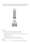
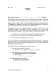
1
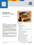
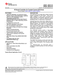
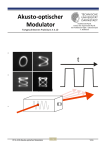
PhlatLight LED
Development Kit Manual
DK-409N Series
Introduction:
PhlatLight LEDs, from Luminus Devices, have been
designed from the ground up to enable a new class of
illumination and projection systems. Benefiting from a
suite of innovations in chip technology, packaging, and
thermal management, PhlatLight LEDs allow designers to
achieve efficient light engine designs and deliver high
brightness solutions.
The DK-409N series of PhlatLight Development Kits was
designed for fast and simple evaluation of PhlatLight
products. The included electrical and thermal solutions
enable customers to easily breadboard or prototype their
system without time consuming and costly development
of driver boards and heat sinks.
Table of Contents:
1.
Key Features 2
2.
Development Kit Contents 2
2.1
Heat Sink 3
2.2
Development Board 3
2.3
Cable Assembly 3
2.4
Thermal Interface Material and Mounting
Hardware 3
3.
User Instructions 4
3.1
Electrical Connections 4
4.
Operating Instructions 5
4.1
Operation in Constant Current Mode 6
4.2
Operation in Triggered Mode 6
4.3
Operation in PWM Mode 7
Capable of providing up to 9A and designed to work with
all CBM series parts and their associated applications,
the DK-409N development kits support various different
drive conditions and use scenarios.
This plug and play solution can easily be
connected to common laboratory equipment through
standard connectors and allows system designers to save
weeks in their development cycles.
960018 Rev A © 2009 Luminus Devices, Inc. All rights reserved.
Page 1
PhlatLight® DK-409N Series Development Kit Manual
1. Key Features
•
Compatible with CBM-360 PhlatLight LED
•
Driver board supplies currents up to 9A
•
On board control for PWM dimming for lighting applications or 0-10V analog input
•
Minimum Pulse width of 20 microseconds
•
External Trigger input for machine vision with 13 preprogrammed pulse durations
2. Development Kit Contents
As seen in Figure 1, the content of each PhlatLight DK-409N Development Kit includes the following
components:
•
Heat sink/development board assembly
•
Cable assemblies
•
Thermal interface materials and mounting hardware
•
User Manual
This development kit was designed with flexible features to allow for easy evaluation of PhlatLight LEDs.
It was not optimized for size or for direct integration in end products. However, the underlying circuit
and thermal design can be used as a reference by system designers. To this effect, the complete design
files including schematics, mechanical drawings, and bills of materials are available upon request.
Figure 1: Single Channel Evaluation Kit Contents
960018 Rev A © 2008 Luminus Devices, Inc. All rights reserved.
Page 2
PhlatLight® DK-409N Series Development Kit Manual
2.1
Heat Sink
The heat sink is a high performance, low cost and compact air cooled copper sub mount with copper fins.
Measuring 82 mm x 65 mm x 38mm, the heat sink occupies a very small volume. The typical thermal
resistance from heat sink to ambient with the fan in operation is 0.3 ºC/W, thereby enabling significant
power dissipation.
The bolt pattern on the front face of the sink allows for easy mounting of all CBM series modules.
2.2
Development Board
The driver circuit, designed around National Semiconductor’s LM3421 IC, is designed to provide up to 9A
of current to any CBM PhlatLight LED. The board is mounted close to the heat sink and LED to ensure
cable lengths are kept at a minimum (<3”). Longer cable lengths will cause increased current ringing
when pulsing the LEDs.
The driver board is fully capable of driving the LEDs in either CW or pulsed mode. The PWM frequency is
set to 25kHz. An external function generator is required for generating the pulse trains in the triggered
mode and external PWM mode.
The driver requires a 24VDC input from an external AC/DC source. The external trigger voltage range is of
5 – 10V and the external PWM voltage input range is between 0 – 10V. Care must be taken to not exceed
these voltages as it may cause permanent damage to the driver board.
2.3
Cable Assembly
Each development kit includes all of the cables necessary for proper setup. The primary cables included
are as follows:
•
Power supply to development board
•
Driver board to LED
For optimum performance, it is not recommended to increase the length of the driver to LED cable. A
longer cable will result in decreased performance when pulsing the LEDs.
2.4
Thermal Interface Material (TIMs) and Mounting Hardware
Also included in the kit are precut sheets of a high performance thermal interface material (eGraf
HiTherm 1205) and the required mounting hardware for the devices.
M2.5x6 screws are provided for attachment of CBM and CSM package types.
Figure 2: TIM cut for CBM and CSM package types.
960018 Rev A © 2008 Luminus Devices, Inc. All rights reserved.
Page 3
PhlatLight® DK-409N Series Development Kit Manual
3. User Instructions
The following procedure explains how to setup the PhlatLight Evaluation Kit. It is recommended that the
table be equipped with ESD protection.
Important Note: The driver board is capable of providing 9A of current to any device. Not all PhlatLight
products can be powered at 9A. Care must be taken to ensure the proper current is applied to the
device. Consult the product data sheets for current limitations of specific devices.
Equipment Required by User
In order to power and use the development kit, some additional equipment is required. Table 1 lists the
type of equipment as well as a suggested part. An additional list of other compatible power supplies is
provided in Appendix B.
Lab Equipment
Recommended Part
24V Lab Power Supply
Lambda ZUP36-12
Oscilloscope
Tektronix TDS 3024B
0-10V Power Supply
Lambda ZUP10-20
Multimeter
Fluke 187
Photodetector
Thorlabs PDA10A
Table 1: Additional Lab Equipment
3.1
Electrical Connections
The following sections assume that the user has all of the equipment listed in Table 1.
1. Prepare the power supply and ensure the power supply being used is capable of providing enough
power to the devices. A single channel at full power will draw up to ~130W at 24V and 5.5A. If
using a variable power supply like the Lambda ZUP36-12, preset the voltage to 24V and set the
current to the maximum. Power off the supply until all connections are established and the
board settings are ready.
2. Attach all of the wiring included in the kit. The black, 6” ERNI cable connects the LED to the
driver board. Check to be sure the short 2-pin fan cable is connected to the driver board at the
J3 position, labeled FAN.
960018 Rev A © 2008 Luminus Devices, Inc. All rights reserved.
Page 4
PhlatLight® DK-409N Series Development Kit Manual
4. Operating Instructions
There are multiple different ways the PhlatLight DK-409N Development Kit can be operated. The LEDs
can be driven in continuous, current controlled mode via on-board POT; PWM controlled via onboard POT
or external signal, or through an external analog voltage and dipswitch for machine vision applications.
Additionally, each channel has inputs for an external function generator signal to pulse the LEDs and is
capable of pulsing at frequencies of 25kHz.
To measure the current going to the LED, use a volt meter and measure the voltage across the sense
resistor on the driver board, which is located at the “R12” position. The pads marked Sense+ and
Sense- can also be used for easier access. (See Figure 3 for details) The current can then be
calculated by the following formula:
I LED =
VSense
RSense
Equation 1
where VSense is the voltage measured across the sense resistor in Volts (V) and RSense is the value of the
sense resistor in Ohms. The sense resistor value is 0.027Ω. The output value will the be current going to
the LED in amps
R12
R15
Figure 3: Driver Locations for R12 and R15
960018 Rev A © 2008 Luminus Devices, Inc. All rights reserved.
Page 5
PhlatLight® DK-409N Series Development Kit Manual
4.1
Operation in Constant Current Mode
1.
2.
3.
Set switch SW3/5 to the “TRIG” position. This will illuminate the green indicator of D6
indicating the driver in triggered mode.
Set the dip switch SW1 to be in “Always ON” mode. The settings for this are included in table
2.
Use the on board Potentiometer R15 to adjust the current to the LED. (See figure 3 for details)
Switch Position
A
B
C
D
Mode
0
1
2
3
4
5
6
7
8
9
10
11
12
13
14
0
0
0
0
0
0
0
0
1
1
1
1
1
1
1
0
0
0
0
1
1
1
1
0
0
0
0
1
1
1
0
0
1
1
0
0
1
1
0
0
1
1
0
0
1
0
1
0
1
0
1
0
1
0
1
0
1
0
1
0
OFF
T1 (50us)
T2 (100us)
T3 (250 us)
T4 (500us)
T5 (1 ms)
T6 (5 ms)
T7 (10 ms)
T8 (25 ms)
T9 (50 ms)
T10 (100 ms)
T11 (250 ms)
T12 (500 ms)
T13 (1 s)
Gated
15
1
1
1
1
Always ON
Table 2: DIP Switch Settings
4.2
Operation in Triggered Mode
1.
2.
3.
Set the maximum desired current to the LED by following step 4.1
Using the DIP switch SW1 select a preprogrammed time interval as shown in Table2 or select
the “gated” function if the time interval will be set by an external source.
Attach an external source capable of providing between 5 – 10 V to J6 as the trigger
mechanism.
a. If a preprogrammed time interval was selected, the LED will light up for that time
period every time the driver board sees a voltage on J6 between 5 – 10V.
b. If the “gated” function was selected, the LED will light up for as long as there is a
voltage applied between 5 – 10V on J6.
960018 Rev A © 2008 Luminus Devices, Inc. All rights reserved.
Page 6
PhlatLight® DK-409N Series Development Kit Manual
4.3
Operation in PWM Mode
1. Set the maximum desired current to the LED by following step 4.1
2. Set Switch SW3 to “PWM” Mode
3. Use switch SW2/4 to select the “POT” position for using the on board Potentiometer R21 to
control the PWM settings or the “EXT” position for using an external analog voltage on J7 in
the range of 0 – 10V to control the PWM settings
a. In the “POT” setting the LED D7 will illuminate indicating that the driver is using the
on board Potentiometer for PWM control
b. In the “EXT” setting the LED D8 will illuminate indicating that the driver is expecting
an external voltage on J7 for PWM control
J7
SW2/4
R21
SW3/5
SW1
J6
Figure 4: Driver Locations for SW1, SW3/5, SW2/4, R21, J6 and J7
960018 Rev A © 2008 Luminus Devices, Inc. All rights reserved.
Page 7